

Page 1
INDUSTRIAL PUMPS - INDUSTRIEPUMPEN
petrochemical, food, mechanical, environmental, printing, chemical, painting, galvanic, textile and ceramic, industry
DM
D
BEDIENUNGS-UND WARTUNGSANLEITUNG
GB
INSTRUCTIONS FOR USE AND MAINTENANCE
DM 03/2014
TÜV NORD Italia
I
S
O
S.r.l.
1
0
0
9
www.debem.it
Page 2

Debem SRL
2014
Die Übersetzung, Vervielfältigung und Anpassung
des ganzen oder eines Teils dieses Dokumentes
mit irgendeinem Mittel sind in allen Ländern
verboten.
Debem SRL
2014
All rights of total or partial translation, reproduction
and adaptation by any means are reserved in all
countries.
www.debem.it
2
Page 3

INHALT
D
SCHREIBEN BEI DER LIEFERUNG 4
EINFÜHRUNG IN DAS HANDBUCH 4
IDENTIFIKATION DER PUMPE 6
IDENTIFIKATIONSCODE 6
BESCHREIBUNG DER PUMPE 7
TECHNISCHE DATEN 8
GARANTIEMODALITÄTEN 12
SICHERHEITSVORSCHRIFTEN 13
HAFTUNGSAUSSCHLUSS BEI CHEMISCHEN REAKTIONEN 15
VORSICHTSMASSNAHMEN FÜR INSTALLATION UND BETRIEB 16
TRANSPORT UND AUFSTELLUNG 17
ANSCHLIESSEN DES PRODUKTKREISLAUFS 20
STROMANSCHLUSS DES MOTORS UND ÜBERPRÜFUNG 21
INBETRIEBNAHME 25
ZEITPLAN FÜR ORDENTLICHE WARTUNGSARBEITEN 26
WARTUNG DES PRODUKTSCHALTKREISES 27
ÖFFNEN DER PUMPE UND INNENREINIGUNG 28
DEMONTAGE 29
ZUSAMMENBAU 30
FEHLERSUCHE 31
AUSSERDIENSTSTELLUNG 33
ENTSORGUNG UND ABWRACKEN 33
ERSATZTEILE 34
GB
INDEX
FOREWORD 4
INTRODUCTION 4
PUMP IDENTIFICATION 6
IDENTIFICATION CODES 6
PUMP DESCRIPTION 7
TECHNICAL FEATURES 8
WARRANTY 12
SAFETY RULES 13
CHEMICAL REACTION DISCLAIMER 15
INSTALLATION/OPERATION PRECAUTIONS 16
TRANSPORTING AND POSITIONING 17
CONNECTING THE PRODUCT CIRCUIT 20
ELECTRICAL MOTOR CONNESCTION AND ROTATION CHECK 21
START UP 25
STANDARD MAINTENANCE TIME-SCHEDULE 26
MAINTENANCE FOR THE PRODUCT CIRCUIT 27
PUMP OPENING AND INTERNAL CLEANING 28
DISASSEMBLY 29
ASSEMBLY 30
TROUBLESHOOTING 31
DECOMMISSIONING 33
DEMOLITION AND DISPOSAL 34
SPARE PARTS 34
SEITE
PAGE
3
info@debem.it
Page 4

SCHREIBEN BEI DER LIEFERUNG
D
Die DM-Magnetkreiselpumpen sind gemäß der Richtlinie
2006/42/EG gebaut.
Daher bieten sie keine Gefahren für den Bediener, wenn sie
nach den Anweisungen in diesem Handbuch benutzt werden.
Das Handbuch muss in gutem Zustand aufbewahrt werden
bzw. der Maschine zum künftigen Nachschlagen für das Wartungspersonal beiliegen.
Der Konstrukteur übernimmt keinerlei Haftung im Fall von Änderung, Manipulierung, zweckfremden Anwendungen, oder
jedenfalls Handlungen in Missachtung dessen, was in diesem
Handbuch steht, welche die Sicherheit, die Gesundheit von
Personen und Tieren, bzw. auch Sachen in Nähe der Pumpe
gefährden können.
Der Konstrukteur wünscht sich, dass Sie die Leistungen der
FOREWORD
GB
The DM magnetic centrifugal pumps pumps have been manufactured in accordance with the 2006/42/EC directives.
Therefore, when used according to the instructions contained
in this manual, the Boxer pumps will not pose any risk to the
operator.
This manual must be kept in good condition and/or be kept
with the machine as a reference for maintenance purposes.
The manufacturer declines any liability concerning any changes,
modications, incorrect use or operation not complying with the
contents of this manual and that may constitute a health and
safety hazard to people, animals or property nearby the pump.
The Manufacturer trusts you will take full advantage of the
performance offered by DM horizontal, centrifugal pumps.
EINFÜHRUNG IN DAS HANDBUCH
D
Dieses Handbuch ist integrierender Bestandteil der Pumpe,
es ist eine SICHERHEITSVORRICHTUNG, die wichtige Informationen enthält, damit der Käufer und sein Personal die
Pumpe installieren, benutzen und während ihrer gesamten
Nutzungsdauer in einem gleichbleibendefzienten und sicheren
Zustand erhalten können.
Zu Beginn jedes Kapitels und jedes Abschnitts wurde eine
Statuszeile geschaffen, die durch Symbole das Personal,
das zu dem Eingriff befugt ist, die obligatorische persönliche
Schutzausrüstung und/oder den Energiestatus der Pumpe
angibt.
Auf das Restrisiko während des Betriebs wird durch entsprechende, in den Text eingefügte Symbole hingewiesen.
DM-Horizontalkreiselpumpen voll ausnutzen können.
Alle technischen Werte beziehen sich auf Standard-DMPumpen (siehe „TECHNISCHE DATEN“), aber es wird darauf
hingewiesen, dass sich die angegebenen Daten durch eine
fortlaufende Suche nach Innovationen und technologischer
Qualität ohne Vorankündigung ändern können.
Die Zeichnungen und jedwedes mit der Maschine zusammen
gelieferte Dokument sind Eigentum des Konstrukteurs, der
sich sämtliche Rechte daran vorbehält und die Weitergabe an
Dritte ohne seine schriftliche Billigung VERBIETET.
JEDWEDE REPRODUKTION DES HANDBUCHS, DES
TEXTES UND DER ABBILDUNGEN ODER VON TEILEN
DAVON IST DAHER STRENG VERBOTEN.
All technical parameters refer to the standard DM models
(please see “TECHNICAL FEATURES”). However, the constant
search for innovation and technological quality means that the
characteristics detailed herein may change without prior notice.
All of the drawings and any other documentation supplied with
the pump are the property of the Manufacturer, who reserves
all rights and FORBIDS distribution to third parties without his
authorization in writing.
THEREFORE REPRODUCTION, EVEN PARTIAL, OF THIS
MANUAL, TEXT OR DRAWINGS IS STRICTLY FORBIDDEN.
Grasch werden im Handbuch Symbole verwendet, um auf besondere Informationen hinzuweisen und diese hervorzuheben,
oder auf Ratschläge, die für die Sicherheit und für einen korrekten Betrieb der Pumpe gegeben werden.
FÜR JEDWEDE KLARSTELLUNG BEZÜGLICH DES INHALTS DIESES HANDBUCHS WENDEN SIE SICH BITTE
AN DEN KUNDENDIENST DES HERSTELLERS.
GB
INTRODUCTION
This manual is an integral part of the pump, and represents a
SAFETY DEVICE. It contains important information that will
assist the purchaser and his personnel in installing and using
the pump and ensuring that the pump is kept in safe and good
working order throughout its working life.
At the beginning of each chapter and section there is a status
bar: its symbols state the personnel qualied for the operation/
s in question, the compulsory individual protective devices to
wear and/or the power state of the pump. Any other hazard that
may occur during operations is highlighted by special symbols
embedded in the text.
Special identication symbols are used to highlight and differentiate particular information or suggestions concerning safety
www.debem.it
and the pump’s correct use.
FOR ANY FURTHER INFORMATION REGARDING THE
CONTENTS OF THIS MANUAL, PLEASE CONTACT THE
MANUFACTURER’S ASSISTANCE DEPARTMENT.
4
Page 5
I
GB
ATTENZIONE:
il personale addetto all’installazione, all’ispezio-
ne e alla manutenzione della pompa deve avere
adeguata preparazione tecnica unita a cognizioni
idonee al campo di applicazione (compatibilità ade-
guate in materia e rischi connessi ad eventuali reazio-
ni chimiche del prodotto da pompare).
INSTALLATORE/MANUTENTORE ELETTRICO:
questa qualifica presuppone una piena conoscenza e
comprensione delle informazioni contenute nel manuale
d’uso del costruttore, competenza tecnica specifica per
effettuare gli interventi di natura elettrica di: allacciamento,
manutenzione ordinaria e/o riparazione.
INTERVENTI STRAORDINARI: identifica gli interventi
riservati a tecnici del servizio di assistenza eseguiti
solo presso le officine del Costruttore.
WARNING
personnel responsible for pump installation,
inspection and maintenance shall possess a suitable
technical background along with knowledge of the
field of application (compatibility of materials and risks
associated with possible chemical reactions of the
product being pumped).
ELECTRICAL/FITTER AND MAINTENANCE
ENGINEER
!
!
D
ACHTUNG: Weist das betreffende Personal darauf
!
hin, dass die beschriebene Arbeit eine Aussetzung
zu Restrisiken mit der Möglichkeit von Gesundheitsschäden oder Verletzungen darstellt, wenn sie nicht
in Einhaltung der Verfahren und Vorschriften erfolgt, die
in Übereinstimmung mit den Sicherheitsvorschriften
beschrieben sind
WARNHINWEIS: Weist das betreffende Personal darauf
hin, dass die beschriebene Arbeit Schäden an der Ma-
schine oder ihren Bauteilen und daraus folgende Risiken
für den Bediener und/oder die Umwelt verursachen kann, wenn
sie nicht gemäß den Sicherheitsvorschriften ausgeführt wird.
HINWEIS: Liefert Informationen zur laufenden Arbeit,
deren Inhalt berücksichtigenswert bzw. wichtig ist.
SYMBOLE FÜR VERPFLICHTENDE PERSÖNLICHE
SCHUTZAUSRÜSTUNG: Diese weisen auf die Verpich-
tung zum Tragen von persönlicher Schutzausrüstung
sowie auf den Energiestatus infolge der Gefahr hin, der
während der Arbeit auftreten kann.
BEDIENER: Diese Qualikation setzt eine volle Kennt-
nis und Verständnis der im Bedienungshandbuch des
Herstellers enthaltenen Informationen sowie spezi-
sche Kompetenzen je nach Einsatzgebiet voraus.
INSTALLATEUR UND WARTUNGSMECHANIKER:
Diese Qualifikation setzt eine volle Kenntnis und
Verständnis der im Bedienungshandbuch des Her-
stellers enthaltenen Informationen, spezische Kompetenzen
zur Durchführung von Installation und ordentlicher Wartung
sowie spezische Kompetenzen je nach Einsatzgebiet voraus.
ACHTUNG: Das zur Installation, Inspektion und
!
Wartung der Pumpe befugte Personal muss eine
entsprechende technische Vorbereitung und dazu
geeignete Kenntnisse auf dem Anwendungsgebiet (adäquate Kompatibilität zu diesem und Risiken in Verbindung
mit eventuellen chemischen Reaktionen des Produkts, das
gepumpt werden soll) aufweisen.
INSTALLATEUR UND WARTUNGSELEKTRIKER:
Diese Qualikation setzt eine volle Kenntnis und Ver-
ständnis der im Bedienungshandbuch des Herstellers
enthaltenen Informationen sowie spezische technische Kompetenzen für die Durchführung von Elektrikerarbeiten voraus,
also Anschluss, ordentliche Wartung und/oder Reparatur.
AUSSERORDENTLICHE EINGRIFFE: Dies weist auf
Eingriffe hin, die den Service-Technikern des Kunden-
dienstes vorbehalten sind und nur in den Werkstätten
des Herstellers durchgeführt werden.
GB
WARNING: this sign warns the relevant personnel
!
that the operation in question involves the risk of
exposure to various types of health hazards or
injuries, unless it is carried out according to current safety
norms.
WARNING: This sign warns the relevant personnel that
the operation in question might damage the machinery
and/or its components, with consequent hazard to the
operator and/or the environment, unless it is carried out in
accordance with current safety norms.
NOTE: This note supplies relevant and important infor-
mation on the current operation.
SYMBOLS FOR COMPULSORY AND PERSONAL SAFETY: indicate compulsory, adequate personal protection
and the hazard/s that might occur during operation
consequent to the power status indicated.
OPERATOR: This qualication implies a full knowled-
ge and understanding of the information contained in
this manual, besides a specic competence in the
eld of employment.
INSTALLER AND MECHANICAL MAINTENANCE
OPERATOR: This qualication implies a full knowledge
and understanding of the information contained in the manu-
facturer’s use manual, a specic competence to carry our
standard installation and maintenance operations beside a
specic competence in the eld of employment.
WARNING Installation, inspection and maintenance
!
personnel must have adequate technical training as
well as an adequate knowledge of their eld of operation (correct compatibility of materials and hazards related to possible chemical REACTIONS OF THE PRODUCT
TO BE PUMPED.
ELECTRICAL INSTALLER-MAINTENANCE OPERATOR: This qualication implies a comprehensive
knowledge and understanding of the information
contained in the manufacturer’s user manual, technical com-
petence specic to electrical operations: connection, standard
maintenance and/or repairs.
EXTRAORDINARY OPERATIONS: identify work restricted to service technicians that can only be carried
out in the manufacturer’s workshop.
5
info@debem.it
Page 6
IDENTIFIKATION DER PUMPE
DM
senza motore - whitout motor
DICHIARAZIONE DI CONFORMITA’
DECLARATION DE CONFORMITE - DECLARACION DE CONFORMIDAD
ERKLÄRUNG BEZÜGLICH EINHALTUNG DER VORSCHRIFTEN - DECLARATION OF CONFORMITY
TIPO/SERIE
TYPE / SERIE- TIPO / SERIE - TYP / SERIE - TYPE / SERIES
FABBRICATO DA:
FABRIQUE PAR - FABRICADA POR - HERGESTELLT VON - MANUFACTURED BY
MODELLO
MODELE - MODELO - MODELL - MODEL
CODICE
CODE - CODE - KODE - CODICE
MATRICOLA
SERIAL NUMBER - MATRICULE - MATRIKELNUMMER - MATRICULA
DEBEM SRL - Via del bosco 41 - 21052 Busto Arsizio (VA) - ITALIA
Questo prodotto è conforme alle seguenti direttive CE/EX e relativi standard armonizzati:
This product complies with the following European Community Directives CE/EX and relating harmonized standards:
Ce produit est conforme aux directives de la Communautè europèenne suivantes CE/EX et les normes correspondantes harmonisées:
Este producto cumple con las siguientes Directrices de la Comunidad Europea CE/EX y relativas normas armonizadas:
Dieses Produkt erfüllt die folgenden Vorschriften der Europäischen Gemeinschaft CE/EXund entsprechende harmonisierte Normen:
2006/42/CE Direttiva Macchine / Machinery Directive / Maschinenrichtlinie / Directive Machines / Directiva Máquinas
CE EMC 89/336/CEE e alla legislazione nazionale che le traspone - CE LVD 73/23/CEE e alla legislazione nazionale che le traspone
UNI EN ISO 12100-1: 2009 – Sicurezza del macchinario. Concetti fondamentali, principi generali di progettazione. Parte 1: terminologia di base, metodologia.
UNI EN ISO 12100-1: 2009 – Safety of the machinery. Fundamental notions, design general principles. Part 1: Basic terminology, methods.
UNI EN ISO 12100-1: 2009 – Sécurité des machines. Concepts fondamentaux, principes généraux de conception. Partie 1 : terminologie de base, méthodologie.
UNI EN ISO 12100-1: 2009 – Sicherheit von Maschinen.. Grundbegriffe, allgemeine Gestaltungsleitsätze. Teil 1: Grundsätzliche Terminologie, Methodologie.
UNI EN ISO 12100-1: 2009 – Seguridad de la maquinaria. Conceptos fundamentales, principios generales de diseño. Parte 1: terminología de base, metodología.
UNI EN ISO 12100-2: 2009 – Sicurezza del macchinario. Concetti fondamentali, principi generali di progettazione. Parte 2: principi tecnici.
UNI EN ISO 12100-2: 2009 – Safety of the machinery. Fundamental notions, design general principles. Part 2: Technical principles.
UNI EN ISO 12100-2: 2009 – Sécurité des machines. Concepts fondamentaux, principes généraux de conception. Partie 2 : principes techniques.
UNI EN ISO 12100-2: 2009 – Sicherheit von Maschinen. Grundbegriffe, allgemeine Gestaltungsleitsätze. Teil 2: Technische Leitsätze.
UNI EN ISO 12100-2: 2009 – Seguridad de la maquinaria. Conceptos fundamentales, principios generales de diseño. Parte 2: principios técnicos.
UNI EN ISO 3746: 2009 – Acustica. Determinazione dei livelli di potenza sonora delle sorgenti di rumore mediante misurazione della pressione sonora. Metodo di controllo
con una supercie avvolgente su un piano riettente.
UNI EN ISO 3746: 2009 – Sound. Determination of sound power levels for noise sources by measuring the sound pressure. Monitoring method with an enveloping surface
on a reecting plate.
inserire qui tipo/serie
inserire qui modello
inserire qui codice
inserire qui matricola
D
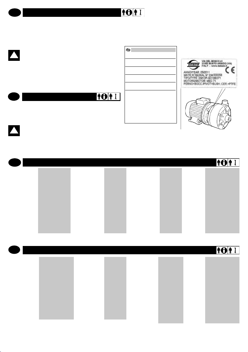
Jede Pumpe ist mit einer Identikationsplakette versehen,
welche die technischen Daten und die Materialien angibt, aus
denen die Pumpe besteht. Bei jedweder Kommunikation mit
dem Hersteller, dem Verkäufer, oder mit
autorisierten Kundendienstzentren sind diese Daten anzugeben.
ACHTUNG: Das Entfernen und/oder Ändern der
!
Identikationsplakette der Pumpe bzw. der auf ihr
angegebenen Daten ist verboteni.
Der Identikationscode, der unter dem Punkt „TYP“ auf der
Plakette erscheint, gibt die Zusammensetzung und die Konstruktionsmaterialien der Pumpe an, damit deren Geeignetheit
bzw. Kompatibilität zu dem Produkt festgestellt werden kann,
das gepumpt werden soll.
GB
PUMP IDENTIFICATION
Each pump is tted with an identication plate detailing its
specication and materials. This data must always be reported in
all communications to the manufacturer, dealer or service
centres.
WARNING: It is forbidden to remove and/or modify
!
the identication plate and/or the data therein.
The identication code * listed aside the TYPE heading, details
the pump composition and manufacturing materials in order
to determine its suitability and compatibility with the product
to be pumped.
D
IDENTIFIKATIONSCODE
DM10
PUMPENMODELL
DM06
DM10
DM15
DM30
P-
PUMPENKÖRPER
P - Polipropilene
FC - PVDF +Cf
S
DRUCKLAGER-RING
S - Standard
(ceramica +
PTFE graffite)
D
O-RING
D - EPDM
V - Viton®
LAUFRAD
DM06
DM10
DM15
DM30
1
1=Ø81
2=Ø70
3=Ø65
1=Ø98
2=Ø85
3=Ø70
1=Ø123
2=Ø 108
3=Ø 90
1=Ø 134
2=Ø 122
3=Ø 110
BEFESTIGUNGEN
N - NPT
B - BSP
* Dotazione di serie motore in eurotensione asincrono trifase (2 poli) 50/60 Hz
N
E
MOTORFLANSCH
E - MEC
U - NEMA
071
MOTORGEHÄUSE
DM06
063
071
DM10
071
080
DM15
090
DM30
090
100
112
GB
IDENTIFICATION CODE
DM10
PUMP MODEL
DM06
DM10
DM15
DM30
* Standard motor is the three-phase induction type with European voltage (2-pole) 50Hz
www.debem.it
P-
PUMP BODY
P - Polypropylene
FC - PVDF +Cf
S
THRUST
WASHER
S - Standard
(ceramic +
PTFE graphite)
D
O-RING
D - EPDM
V - Viton®
6
IMPELLER
DM06
DM10
DM15
DM30
1
1=Ø81
2=Ø70
3=Ø65
1=Ø98
2=Ø85
3=Ø70
1=Ø123
2=Ø 108
3=Ø 90
1=Ø 134
2=Ø 122
3=Ø 110
N
CONNECTION
N - NPT
B - BSP
E
MOTOR
FLANGE
E - MEC
U - NEMA
071
MOTOR CASING
DM06
063
071
DM10
071
080
DM15
090
DM30
090
100
112
Page 7

BESCHREIBUNG DER PUMPE
D
Vorgesehene Verwendung
Die DM-Magnetkreiselpumpen sind zum batteriebetriebenen
Pumpen von Flüssigkeiten mit einer aufscheinenden Viskosität von 1 bis 150 cps entwickelt und gebaut, wobei diese
chemisch für die Bauteile der Pumpe verträglich sein müssen.
Der Betrieb der Pumpe ist bei Betriebstemperaturen der Flüssigkeit von -10° C bis maximal 65° C für Pumpen aus PP und
von -10° C bis 95° C für Pumpen aus PVDF je nach dem Materialtyp zulässig, aus dem die Pumpe besteht (siehe TECHNISCHE DATEN, Seite 9)
Die DM-Magnetkreiselpumpen sind für einen Betrieb bis maximal 3500 Umdr./Minute vorgesehen:
GB
PUMP DESCRIPTION
Recommended use
The DM centrifugal pumps made from resin have been designed
and manufactured to pump below head liquids having an apparent viscosity between 1 and 150 cps, and that are chemically
compatible with the components of the pump.
Fluid service temperatures must range from -10°C to a maximum of 65°C for PP pumps and from -10°C to 95°C for PVDF
pumps; according to the type of material used to build the pump
(pls refer to TECHNICAL CHARACTERISTICS pg. 9).
DM centrifugal pumps are designed for a max working speed
of 3500 revs/min.
D
Funktionsprinzip
Die DM-Magnetkreiselpumpen müssen mit entsprechenden
Vorkehrungen unter Anschlag installiert werden, um eine Strudelbildung und das daraus folgende Ansaugen von Luftblasen
zu vermeiden. Der Betrieb darf ausschließlich nur bei GANZ
EINGETAUCHTER PUMPE erfolgen. Ein Magnetpaar steuert
den Betrieb der Pumpe. Der an der Motorwelle angebrachte
äußere Magnet überträgt die Bewegung zum inneren Mag-
neten, der am hermetisch isolierten Laufrad x montiert ist.
Das Laufrad der Pumpe ist nicht physisch mit der Motorwelle
verbunden, dadurch entfallen Dichtungen und dementsprechend Verluste der gepumpten Flüssigkeit durch Verschleiß.
Die pumpende Baugruppe ist mit einer niedrigen Anzahl an
ASYNCHRONER DREIPHASIGER, 2-POLIGER MOTOR
- Euro-Spannung;
- Betrieb S1 (Dauerbetrieb)
- Isolierung der Klasse F
- Schutzgrad IP 55
ATTENZIONE: Wenn der Schwankungsbereich
der Umgebungstemperatur und der Prozesstem-
!
peraturen der Flüssigkeit in Nähe der Höchsttemperatur der Pumpe liegt, muss je nach den Materialien,
aus denen diese besteht (siehe TECHNISCHE DATEN S.
10) an der Anlage eine Schutzvorrichtung installiert werden, welche den Betrieb bzw. das Erreichen des Temperaturgrenzwertes verhindert.
THREE-PHASE/2 POLES ASYNCHRONOUS MOTOR
- Euro tension;
- S1 status (continuous service)
- Class F insulation;
- IP 55 protection rating.
WARNING: Whenever the variation range of envi-
!
ronmental temperature and of the uid process
temperature approaches the maximum pump temperatures according to the pump’s construction materials
(pls refer to TECHNICAL CHARACTERISTICS, pg 10), it is
necessary to safeguard the plant installing a protection
device stopping the pump and/or preventing it from reaching the threshold temperature.
Bauteilen konstruiert, wodurch sie sich äußerst leicht warten
lässt. Die standardmäßig eingesetzten Materialien sind Polyp-
ropylen (PP) und Vinyliden-Polyuorid (PVDF)
Die Pumpen dürfen nicht trocken laufen. Schmutzige Flüssigkeiten können ihre Lebensdauer verkürzen.
ACHTUNG: Jedwede andere Verwendung der
DM-Horizontalkreiselpumpe als oben angegeben
!
wird als unsachgemäß angesehen und daher von
der Firma Debem verboten.
GB
Working principles
DM magnetic drive centrifugal pumps must be installed
below head with appropriate procedures to avoid vortex formation and consequent air bubble suction. The pump must
work ONLY when FLOODED.
A couple of magnets leads the operation of the pump; the outer magnet placed on the drive shaft transmits the motion to
the inner magnet integrated with the impeller that is hermeti-
cally insulated. The pump impeller is not physically xed to
the drive shaft, seals are therefore eliminated and this consequently avoids leakages of the liquid drawn by the pump
which are usually due to its wear and tear. The pump head is
manufactured with few components, thus the maintenance of
which becomes extremely easy. The materials used as stan-
dard are polypropylene (pp) and polyvinylidene uoride (pvdf).
The pumps can’t run dry. Dirty liquids can reduce the pump life
WARNING: use of DM horizontal, centrifugal pum-
!
ps or anything other than that previously descri-
bed is to be considered improper use and is forbidden by Debem.
7
info@debem.it
Page 8
D
Unsachgemäße Verwendungen
Die Verwendung der DM-Pumpe ist insbesondere für Folgendes VERBOTEN:
- Das Pumpen von Benzin und/oder entammbaren Flüssigkeiten;
- Das Pumpen von Lebensmittelüssigkeiten;
- Der Einsatz mit entgegengesetzter Drehrichtung zur festgelegten;
- Der Einsatz mit automatischer Füllung;
- Der Einsatz mit Ansaugung bei Vorhandensein von Strudeln,
Wirbeln, oder Luftblasen;
- Der Einsatz im Leerlauf;
- Der Einsatz mit zu pumpenden Flüssigkeiten, die chemisch
für die Baumaterialien nicht verträglich sind; - Der Einsatz von
Produkten mit Schwebeteilchen, deren spezisches Gewicht
höher als das der Flüssigkeit ist (z.B. Wasser mit Sand);
- Bei Temperaturen und Produkteigenschaften, die nicht den
Eigenschaften der Pumpe entsprechen;
- Der Einsatz mit besonders hartem und/oder stark mit Schüttprodukten belastetem Wasser.
GB
Improper use
It is SPECIFICALLY forbidden to use DM pumps:
- for pumping petrol and/or ammable liquids;
- for pumping food liquids;
- with an opposite rotation to the one specied;
- in self-priming working conditions;
- for suction in the presence of vortexes, turbulence or air
bubbles;
- for vacuum service;
- with liquids that are chemically incompatible with the manufacturing materials;- with products in suspension that have a
higher specic weight than the liquid (e.g. water and sand);
- with product temperatures and characteristics of the pump;
- with water that is particularly hard and/ or full of deposits.
WARNING: due to the wide variety of products and
!
chemical compositions, the operator is conside-
ACHTUNG: Angesichts der zahllosen Varietäten
von Produkten und chemischen Zusammenset-
!
zungen wird der Benutzer als der beste Kenner
der Verträglichkeit und der Reaktionen mit den Baumaterialien der Pumpe angesehen. Deshalb muss er vor deren
Einsatz mit Sachverstand die notwendigen Prüfungen
und Tests durchführen, um Gefahrensituationen zu vermeiden, selbst wenn diese nur entfernt möglich sind, da
diese dem Hersteller nicht bekannt sein können und ihm
daher nicht zur Last gelegt werden können.
ACHTUNG: Jede Verwendung der Pumpe außer-
!
halb der Anweisungen, die im Bedienungs- und
Wartungshandbuch angegeben sind, verletzt die
Sicherheitsanforderungen.Die Risiken in Verbindung mit
der Benutzung der Pumpe wurden unter den präzisen
Bedingungen analysiert, die vom Bedienungs- und Wartungshandbuch vorgeschrieben sind: die Analyse der Risiken in Verbindung mit dem Anschluss an andere Komponenten der Anlage wird dem Installateur übertragen.
red to be the best evaluator of reactions and compatibility
with the pump’s construction materials. Therefore, before
use, carry out all necessary checks and tests to avoid any
possible hazardous situation, that cannot be predicted or
for which the manufacturer cannot be held liable.
WARNING: use of the pump that does not com-
!
ply with the instructions indicated in the use and
maintenance manual will cancel compliance to the
requirements for safety.
The risks associated with the use of the pump under the
exact conditions set forth in the use and maintenance
manual have been analysed, whilst the analysis of the
risks associated with the interface with other system
components must be carried out by the installer.
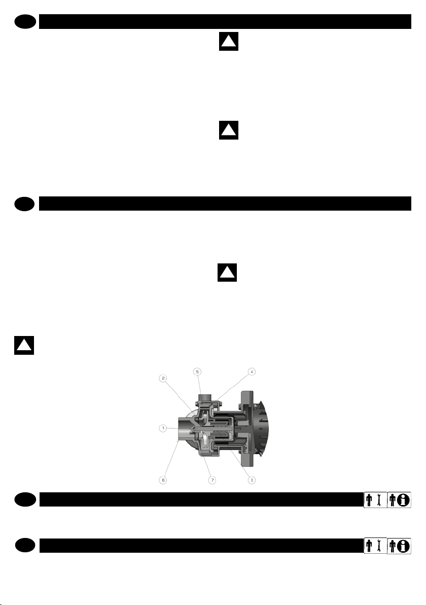
Bauteile Materialien
1
Welle
Drucklager
2
Laufrad
3
Buchse PTFE + 30 % Graphit
4
O-Ring VITON/EPDM
5
Laufrad PP/PVDF+CF
6
Pumpenkörper PP/PVDF+CF
Drucklager
7
Zylinderkopf
TECHNISCHE DATEN
D
Die Daten bezüglich der Leistungen beziehen sich auf die Standardausführungen. Die Werte für „NENNDURCHSATZ“ und „MAX. Förderhöhe“ beziehen sich auf das Pumpen von Wasser bei 18° C mit freier Ansaugung und Förderleistung.
TECHNICAL SPECIFICATIONS
GB
The data related to performance refer to standard procedures. The NOMINAL ow and the MAX head values refer to pumping
of water at 18°C with free-ow suction and delivery.
www.debem.it
Aluminiumkeramik
99,7 %
PTFE + 30 % Graphit
Aluminiumkeramik
99,7 %
8
components material
1
Shaft
Thrust bearing
2
washer
3
Bearing
4
O-ring VITON/EPDM
5
Impeller PP/PVDF+CF
6
Pump Casing PP/PVDF+CF
Head thrust
7
bearing washer
Alumina
Ceramics 99,7%
PTFE +
30% Graphite
PTFE +
30% Graphite
Alumina
Ceramics 99,7%
Page 9
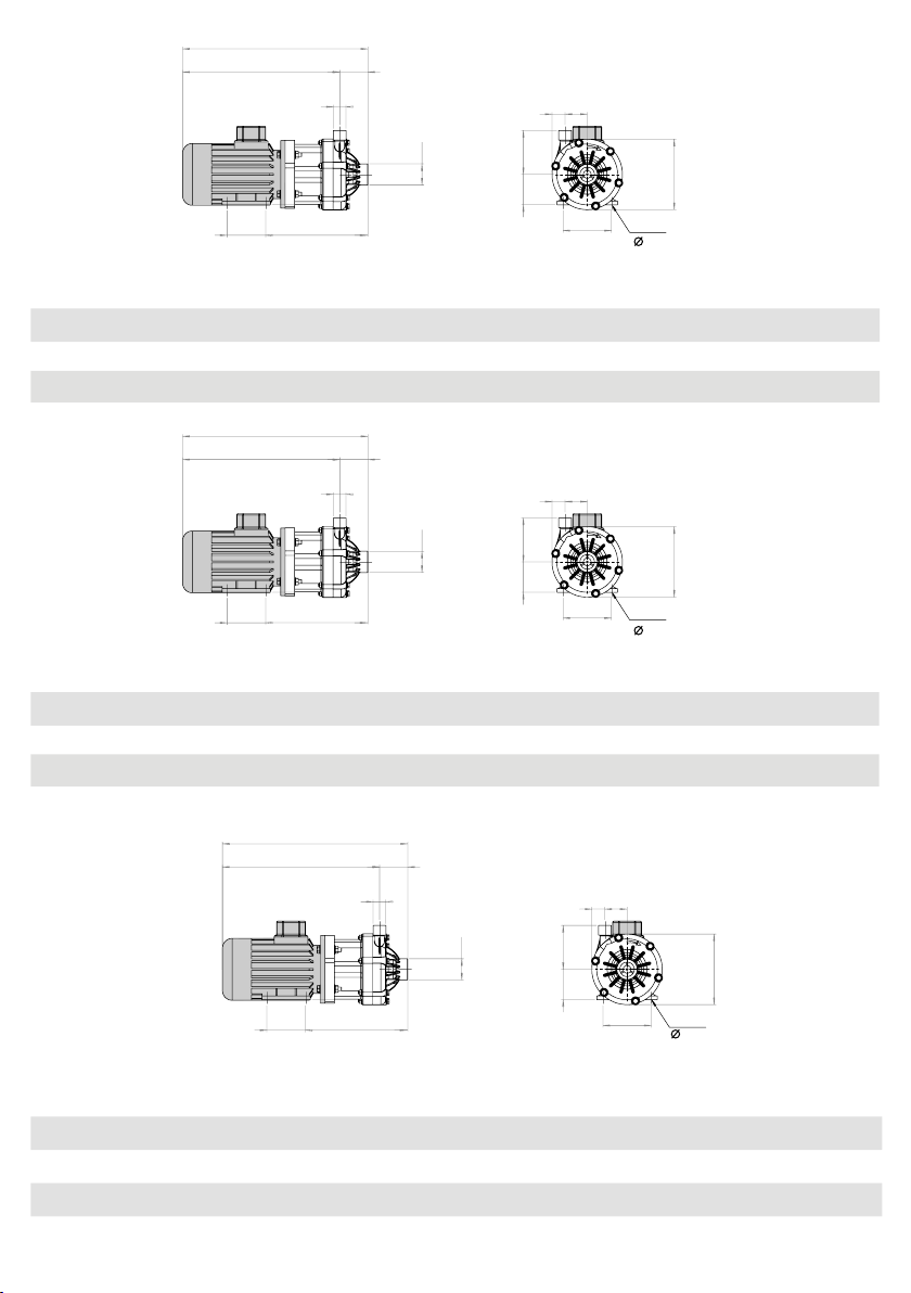
A
DM06
A
A
B
H
C
E
F
G
M L
N O
P
4 fori/hole
7
mod.
Motor
motor
Leistung
power
A B C E F G H L M N O P
DM06 IEC 63 0,25 Kw 383 325 58 3/4” M
DM06
DM06
IEC 71 0,37 Kw 404 346 58 3/4” M
NEMA 56C 0,5 Hp 436 377 58 3/4” M
DM10
B
H
mod.
Motor
motor
Leistung
power
A B C E F G H L M N O P
DM10 IEC 71 0,55 Kw 417 349 68 1” M
DM10
DM10
IEC 80 0,75 Kw 459 391 68 1” M
NEMA 56C 0,75 Hp 448 380 68 1” M
DM10 NEMA 143TC 1,00 Hp 482 414 68 1” M
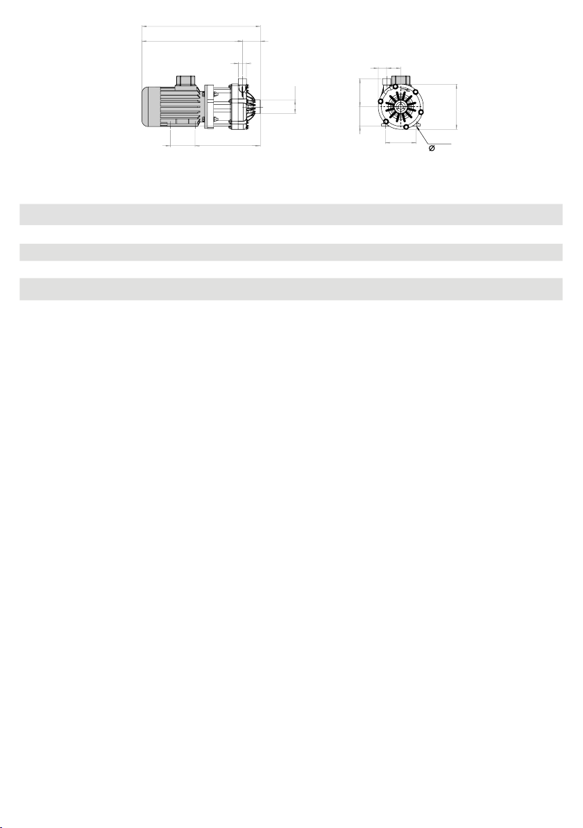
C
E
G
DM15
B
C
E
*
1” F*211 80 27 46 63 91 100 6,7 7
*
1” F*217 90 27 46 71 91 11 2 7,5 7,8
*
1” F*228 90 27 46 89 91 11 2 - -
M L
F
N O
P
*
1”1/2 F*229 90 25 47 71 91 11 2 8,6 9
*
1”1/2 F*346 100 25 47 80 91 125 10,6 11
*
1”1/2 F*240 90 25 47 89 91 11 2 - -
*
1”1/2 F*245 90 25 47 89 91 11 2 - -
M L
4 fori/hole
7, 10, 7, 7
KgPPKg
PVDF
KgPPKg
PVDF
mod.
H
Motor
motor
Leistung
power
A B C E F G H L M N O P
G
DM15 IEC 90 1,5 Kw 489 408 81 1”
DM15 IEC 90 2,2 Kw 489 408 81 1”
DM15 NEMA 145 TC 3 Hp 530 449 81 1”
F
1/4 M*1”1/2 F*
1/4 M*1”1/2 F*
1/4 M*1”1/2 F*
9
N O
P
4 fori/hole
10, 8.73
KgPPKg
PVDF
298 125 35 62 90 125 140 - -
298 125 35 62 90 125 140 - -
327 127 34 62 88 125 139 - -
info@debem.it
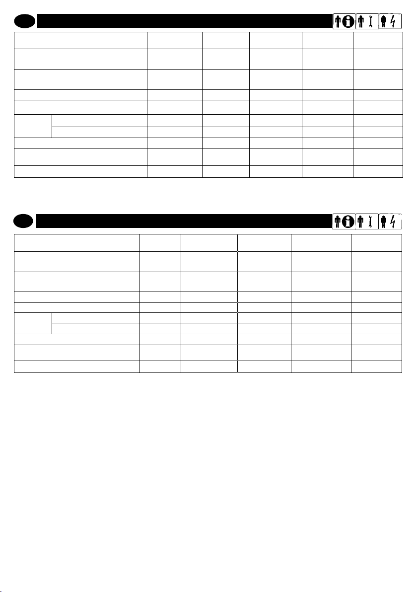
Page 10
A
DM30
B
H
C
E
F
G
M L
N O
P
4 fori/hole
10, 12, 12, 8.73, 10.3
mod.
Motor
motor
Leistung
power
A B C E F G H L M N O P
DM30 IEC 90 2,2 Kw 499 408 91 1”1/2 M
DM30
IEC 100 3 Kw 524 433 91 1”1/2 M
DM30 IEC 112 4 Kw 549 458 91 1”1/2 M
DM30 NEMA 145TC 3 Hp 541 450 91 1”1/2 M
DM30 NEMA 184TC 5 Hp 608 517 91 1”1/2 M
*
2 F*308 125 31 66 90 140 140 - -
*
2 F*315 140 31 66 100 140 160 - -
*
2 F*322 140 31 66 11 2 140 190 - -
*
2 F*337 127 31 66 88 140 139 - -
*
2 F*328 139 31 66 11 4 140 190 - -
KgPPKg
PVDF
www.debem.it
10
Page 11
I
GB
ATTENZIONE:
il personale addetto all’installazione, all’ispezio-
ne e alla manutenzione della pompa deve avere
adeguata preparazione tecnica unita a cognizioni
idonee al campo di applicazione (compatibilità ade-
guate in materia e rischi connessi ad eventuali reazio-
ni chimiche del prodotto da pompare).
INSTALLATORE/MANUTENTORE ELETTRICO:
questa qualifica presuppone una piena conoscenza e
comprensione delle informazioni contenute nel manuale
d’uso del costruttore, competenza tecnica specifica per
effettuare gli interventi di natura elettrica di: allacciamento,
manutenzione ordinaria e/o riparazione.
INTERVENTI STRAORDINARI: identifica gli interventi
riservati a tecnici del servizio di assistenza eseguiti
solo presso le officine del Costruttore.
WARNING
personnel responsible for pump installation,
inspection and maintenance shall possess a suitable
technical background along with knowledge of the
field of application (compatibility of materials and risks
associated with possible chemical reactions of the
product being pumped).
ELECTRICAL/FITTER AND MAINTENANCE
ENGINEER
!
!
D
TECHNISCHE DATEN Maßeinheiten DM
Ansaugung
(f = Innenanschluss/m = Zapfenanschluss)
Förderanschluss
(m = Zapfenanschluss)
Max. Umdr. Pumpe (Nennwert) Umdr./ Min.
Max. Einsatztemperatur der Pumpe
Max. Durchsatz*
Max. Förderleistung*
(bei 3000 Umdr./Min. mit Wasser bei 18° C)
Schallpegel dB (A)
Die Werte beziehen Sie auf eine Pumpe mit freier Ansaugung und Förderleistung mit Wasser bei 18° C.
GB
TECHNICAL DATA
Suction Connection
(f = female thread / m = male thread)
Delivery connection
(m = male thread)
MAX pump rev. (nominal)
MAX pump temperature
MAX head *
MAX ow rate*
(at 3000 rev/min with water at 18°C)
Noise dB (A)
- PP
- PVDF
- PP
- PVDF
Zoll
Zoll
° C
° C
m
m3/h
unit
inches
inches
r.p.m. 3500 3500 3500 3500
C°
C°
m 8,5 13,8 19,8 24
mc/h 6,5 13 23,5 36
G BSP o NPT
06
G 1” F
G BSP o NPT
G 3/4” M
BSP o NPT
3500 3500 3500 3500
65 65 65 65
95 95 95 95
8,5 13,8 19,8 24
6,5 13 23,5 36
48 52 58 58
DM
06
G 1” F
G 3/4” M
BSP o NPT
65 65 65 65
95 95 95 95
48 52 58 58
DM
10
G 1” 1/2 F
G BSP o NPT
G 1” M
BSP o NPT
DM
10
G 1” 1/2 F
G BSP o NPT
G 1” M
BSP o NPT
DM
15
G 1” 1/2 F
G BSP o NPT
G 1” 1/4 M
BSP o NPT
DM
15
G 1” 1/2 F
G BSP o NPT
G 1” 1/4 M
BSP o NPT
DM
30
G 2” F
G BSP o NPT
G 1” 1/2 M
BSP o NPT
DM
30
G 2” F
G BSP o NPT
G 1” 1/2 M
BSP o NPT
* The values refer to a pump with open suction and delivery with water at 18°C
11
info@debem.it
Page 12

GARANTIEMODALITÄTEN
D
PRESCRIZIONI DI SICUREZZA
Die DM-Magnetkreiselpumpen sind ein Qualitätsprodukt, das von
allen, die sie besitzen, mit voller Zufriedenheit
anerkannt wird.
Sollte bei ihm eine Anomalie auftreten, wenden Sie sich bitte an den
KUNDENDIENST DES HERSTELLERS, den Verkäufer, oder an Ihr
nächstgelegenes Kundendienstzentrum, das Ihnen in der kürzest
möglichen Zeit zu Hilfe kommen wird.
Geben Sie in jedem Fall Folgendes an:
A- die vollständige Adresse
B- die Identikation der Pumpe
C- die Beschreibung der Anomalie
Für alle DM-Pumpen gelten folgende Garantiebedingungen:
1- Für die Pumpe wird eine Garantie von 12 Monaten auf alle mecha
nischen Teile gewährt, die als defekt befunden werden. Die Garantielaufzeit wird ab dem Auslieferungsdatum berechnet.
2- Jeder Defekt muss dem Hersteller innerhalb von 8 Tagen gemel
det werden.
3- Arbeiten unter Garantie werden ausschließlich nach Ein- bzw.
Übersendung der defekten Pumpe in unseren Werkstätten durch
geführt.
4- Im Fall einer Reparatur oder eines Austauschs von Teilen der
Pumpe wird die Garantie nicht verlängert.
5- Die defekten Teile müssen an den Hersteller zurückgesandt wer
den, der sich eine Überprüfung derselben in seiner eigenen Werkstatt vorbehält, um den tatsächlichen Defekt festzustellen, oder im
Gegenteil die externen Gründe zu identizieren, die den Schaden
verursacht haben können. Falls sich die Teile als nicht defekt er
weisen sollten, behält sich der Hersteller das Recht vor, den vollen
Preis der vorher unter Garantie ausgetauschten Teile in Rechnung
zu stellen.
Der Hersteller übernimmt die Kosten und Risiken des Transports der
defekten Teile und der reparierten, oder zum Austausch gelieferten
WARRANTY
GB
The high quality of DM magnetic drive centrifugal pumps has
been conrmed to us on many occasions by the end users.
However, should any defect appear, please contact the
Manufacturer’s After-Sales Service, your dealer or the nearest
Customer Service Department who will help you as quickly
as possible.
In any case, please provide:
A – Your complete address
B – Pump identication
C – Description of the anomaly.
All the DM pumps are covered by the following warranty:
1. Guarantee on mechanical parts of all DM pumps is for 12
months. The warranty period is calculated from the date of
delivery.
2. Every fault must be notied to the Manufacturer within 8 days.
3. Repairs under warranty will only be carried out in our workshop after receiving the pump.
4. The replacement or repair of parts does not extend the
warranty.
5. Faulty parts must be forwarded to the Manufacturer who
reserves the right to test them in this own workshop in order to
identify the fault or any external reason that may have caused
it. Should the parts be found not faulty, the Manufacturer reserves the right to invoice the total cost of the parts that had
been replaced under this warranty.
The Manufacturer is not liable for costs and risks connected
to transportation of faulty and repaired parts and neither for
those supplied as spare parts, including possible custom duties.
www.debem.it
Teile einschließlich eventueller Zollgebühren in keinem Fall. Die Re
paratur oder der Austausch der defekten Teile stellt die volle Erfüllung
der Garantieverpichtungen dar. Die Garantie deckt KEINEN indi
rekten Schaden ab und insbesondere nicht die eventuell fehlende
Produktion. Außerdem sind von der Garantie alle normalen Ver
brauchsmaterialien bzw. Verschleißteile (Dichtungen). Unter die Garantie fallen keine Teile, die aufgrund von Nachlässigkeit bzw. Achtlosigkeit beim Gebrauch, falscher Installation, oder fehlender und/oder
falscher Wartung beschädigt wurden, sowie Transportschäden und
Schäden durch jedweden Umstand, der nicht auf Betriebs- oder Her
stellungsmängel zurückzuführen ist.
Insbesondere sind von der Garantie ausgeschlossen:
- Schäden, die durch falsche Verwendung oder Installation an der
Anlage verursacht sind;
- Verwendung der Pumpen, die von dem abweicht, was der Käufer
zum Zeitpunkt der Bestellung erklärt hat;
-
- Schaden durch Trockenbetrieb und/oder Betrieb bei Vorhandensein
von Luftblasen;
- Durch Abrieb verursachte Schäden;
-
- Von Fremdkörpern in der Pumpe verursachte Schäden:
- Schäden, die durch gegenläuge Drehung des Motors und der
Pumpe verursacht sind;
- Verwendung der Pumpen bei höheren Temperaturen als erlaubt:
-
- Schäden an den mechanischen Dichtungen (da diese Verschleiß
teile sind), ausgenommen von offensichtlichen Herstellungsmängeln;
- Schäden, die durch besonders durch Schuttprodukte belastetes
Wasser.
Die Garantie ist in allen Fällen einer zweckfremden Verwendung oder
falscher Anwendungen sowie bei Nichtbeachtung der Informationen
ausgeschlossen, die in diesem Handbuch enthalten sind.
Für jeden Streitfall ist der Gerichtsstand Busto Arsizio zustän
dig.
Repair and replacement of faulty parts entirely fulls the warranty.
This warranty DOES NOT cover any indirect damages, in particular lost production. Moreover, the warranty does not cover
any consumable materials (gaskets).
The warranty does not include parts damaged as a consequence of carelessness, neglect, incorrect installation, lack of
and/or incorrect maintenance, or damages due to transportation or to any other reason or event that is not directly linked to
functioning or manufacturing defects.
The following are specically excluded from the warranty:
- any damage caused by incorrect use or installation of the plant;
- use of the pump other than that declared by the purchaser
at the time of order;
- any damage cause by working in dry conditions and/or presence of air bubbles;
- any damage caused by abrasion;
- any damage caused by foreign matters in the pump;
- any damage caused by reverse rotation of the pump or motor;
- any damage caused by using the pump above the maximum
allowed temperature;
- any damage to mechanical sealing (being subject to wear),
except when a manufacturing defect is obvious;
- any damage caused by water with a high content of deposits.
The warranty is void in all cases of improper or incorrect use
and in case of negligence in following the information herein
contained.
For any controversy, the place of jurisdiction is Busto
Arsizio.
12
-
-
-
-
-
-
Page 13

SICHERHEITSVORSCHRIFTEN
D
PRESCRIZIONI DI SICUREZZA
Gefährliche, unüberlegte, oder den Sicherheitsvorschriften und
den Angaben in diesem Handbuch zuwiderlaufende Praktiken
können schwere Verletzungen, Sachschäden und sogar den
Tod verursachen. Diese können dem Hersteller nicht zur Last
gelegt werden.
ACHTUNG: Diese Anweisungen sind dafür uner
lässlich, dass die Pumpe den Sicherheitsanfor-
!
derungen entspricht. Sie müssen daher gekannt,
möglich gemacht, begriffen und eingehalten werden.
ACHTUNG: Das zur Installation, Inspektion und
Wartung der Pumpe befugte Personal muss eine
!
entsprechende technische Vorbereitung und da
neben geeignete Kenntnisse auf dem Anwendungsgebiet
(Kompatibilität zu diesem und Risiken in Verbindung mit
eventuellen chemischen Reaktionen des Produkts, das ge
pumpt werden soll) aufweisen.
ACHTUNG: Jede Verwendung der Pumpe außer
!
halb der Anweisungen, die im Bedienungs- und
Wartungshandbuch angegeben sind, verletzt die
Sicherheitsanforderungen und lässt die Garantie verfallen.
ACHTUNG: Vor Arbeiten an der Pumpe bzw. vor der
Durchführung von Wartungs- oder Reparaturarbei
!
ten ist Folgendes notwendig:
A- Entleerung des Produktes, das gepumpt wird;
B- Durchspülen des Inneren mit einer geeigneten (nicht
entammbaren) Flüssigkeit;
C- Stoppen des Pumpenmotors;
D- Schließen der manuellen Produktsperrventile (Ansau
gung und Förderung)
E- Abschnitttrennung der Versorgungsspannung des Pum
penmotors;
F- Anlegen von geeigneter Schutzausrüstung vor der Arbeit
(Gesichtsmasken, Handschuhe, geschlossene Schuhe,
Schürzen usw.)
SAFETY INSTRUCTIONS
GB
Dangerous or hazardous practices or practices not
complying with the safety rules and with that recommended
herein may cause injuries, material damage and even death
for which the manufacturer cannot be held responsible.
WARNING: these instructions are indispensable
for the pump to comply with safety requirements,
!
therefore they must be made known, available
and abided to.
WARNING: the personnel in charge of installing,
inspecting and servicing the pumps must have
!
adequate technical knowledge and training in the
eld of application (compatibility and hazards related to
possible chemical reaction of the product/s to pump).
WARNING: use of the pump that does not comply
to the instructions indicated in the use and main-
!
tenance manual will invalidate all warranty and
safety requirements.
WARNING: before any operation on the pump and/
or before any maintenance or repair, proceed as
!
follows:
A – discharge the product being pumped;
B – proceed with washing the inside with appropriate liquid
(non-ammable);
C – stop the pump motor;
D – close the manual, shut-off valves (suction and delivery
of product);
E - section power to the pump motor;
-
-
-
-
-
-
-
13
ACHTUNG: Vor dem Einsatz der Pumpe muss man
sich vergewissern, dass die Flüssigkeit, die ge
!
pumpt werden soll, mit den Baumaterial kompatibel ist: GEFAHR VON KORROSION, AUSTRETEN DES PRODUKTES UND/ODER EXPLOSIONEN DURCH CHEMISCHE
REAKTIONEN.
Bei der Installation und beim Einsatz sind folgende allge
meine Vorsichtsmaßnahmen einzuhalten:
- Kontrollieren, ob die Pumpe ganz eingetaucht ist der Flüs
sigkeitsspiegel nach Möglichkeit mindestens 0,5 m darüber
ist;
- Kontrollieren, ob in der behandelten Flüssigkeit keine
Festkörper sind bzw. in sie hineingelangen können;
- Kontrollieren, ob es keine Einschränkungen bei der An
saugung der Pumpe gibt, damit Kavitationsphänomene
und Überlastung des Elektromotors vermieden werden;
- Kontrollieren, ob die Anschlussleitungen geeignet und
widerstandsfähig sind, und ob nicht die Pumpe deren Ge
wicht trägt;
- Wenn die Pumpe über längere Zeiträume inaktiv bleiben
soll, muss sie sorgfältig gereinigt werden, indem man eine
(nicht entammbare) Reinigungsmittelüssigkeit, die mit
den Materialien der Pumpe kompatibel ist, in ihr zirkulieren
lässt;
- Wenn die Pumpe über längere Zeiträume ausgeschaltet
bleiben soll, ist es angebracht, in ihr vorbeugend einige Mi
nuten lang sauberes Wasser zirkulieren zu lassen, um die
Gefahr von Verkrustungen zu vermeiden;
- Die Pumpe immer vor möglichen zufälligen Stößen durch
in Bewegung bendliche Gegenstände oder anstoßende
Materialien schützen, die sie beschädigen und/oder bei
Kontakt reagieren können.
- Die Umgebung vor Spritzern schützen, die durch zufällige
Defekte an der Pumpe entstehen;
F – Wear suitable individual protection before any intervention (masks, gloves, closed shoes, aprons, etc.).
WARNING: before using the pump, ensure that the
uid to pump is compatible with the manufactur-
!
ing materials: CORROSION, LEAKAGE AND/OR
EZPLOSION HAZARSDS DUE TO CHEMICAL REACTIONS.
For the installation and use, take the following precautions:
- check that the pump is ooded and the level is at least
0,5 m higher;
- Check that no solid particles are or could oat in the uid;
- Check that there are no constraints to the pump suction,
thus avoiding cavitations and electrical motor strain;
- Check that the connecting pipes are suitable and resistant
and that the pump does not bear their weight;
- If the pump is to be inactive for long periods, clean it thor-
oughly with a detergent uid (non-ammable) compatible
with the pump’s construction materials;
- if the pump must be turned off for a long period of time,
before doing so circulate clean water for some minutes to
avoid incrustations;
- always protect the pump against possible collisions
caused by moving means or by various blunt materials
that may damage it or react with its materials;
- protect the pump’s surrounding environment from
splashes caused by accidental pump failure;
- Supply an adequate guard to collect and direct the treated
product that could leak.
-
-
-
-
-
-
info@debem.it
Page 14

D
PRESCRIZIONI DI SICUREZZA
- Für eine angemessene Schutzvorrichtung sorgen, die
Produkt, das austreten könnte, sammelt und in einen sicheren Bereich ableitet.
ACHTUNG: Der Trockenbetrieb der DM-Pumpe ist
VERBOTEN. Der Trockenbetrieb ruft ein Schmel-
!
zen der in schleifende Reibung geratenen Bautei-
le und in der Folge möglicherweise einen Brand hervor.
ACHTUNG: Der Einsatz der Pumpe für eine selbst-
!
füllende Installation ist VERBOTEN; Die Sauglei-
tung muss immer unter Anschlag installiert und
fern von Strudeln oder Turbulenzen sein, die ein Eindringen von Luft verursachen würden.
ACHTUNG Bei Einsatz zum Pumpen von aggres-
!
siven, giftigen, oder gesundheitsgefährdenden
Flüssigkeiten muss an der Pumpe ein angemessener Schutz zur Rückhaltung und Sammlung und eine
Meldevorrichtung im Fall eines Austrittes installiert werden: GEFAHR VON VERSCHMUTZUNG, KONTAMINATION, VERLETZUNGEN UND/ODER TOD.
ACHTUNG: Die Benutzung der Pumpe mit Flüs-
!
sigkeiten, die nicht mit den Materialien der Bau-
teile kompatibel sind, oder in einer Umgebung,
wo nicht kompatible Flüssigkeiten vorhanden sind, ist
verboten.
ACHTUNG: Die Installation der Pumpeohne Pro-
!
duktsperrventile an der Absaugung und der För-
derung für die Abschnitttrennung im Fall eines
Lecks ist verboten. GEFAHR VON UNKONTROLLIERTEM
AUSTRITT DES PRODUKTES.
ACHTUNG: Wenn der Benutzer das Risiko vorhersieht, dass die von diesem Handbuch vorgesehe-
!
nen Temperaturgrenzwerte überschritten werden,
muss an der Anlage eine Schutzvorrichtung eingebaut
werden, die den Betrieb bzw. das Erreichen des Temperaturgrenzwertes (Flüssigkeit und Umgebung) von 95° C für
PVDF-Pumpen und von 65° C für Pumpen aus PP (Polypropylen) verhindert.
ACHTUNG: Die Pumpe muss immer unabhängig
von jedem anderen Organ, das an sie angeschlos-
!
sen ist, geerdet sein.
ACHTUNG: Aggressive, giftige, oder gefährliche
Flüssigkeiten können schwere Körperverletzun-
!
gen und/oder Gesundheitsschäden verursachen,
daher ist es verboten, an den Hersteller oder eine Service-Werkstatt eine Pumpe zurück zu senden, die Produkte dieser Art enthält: Vor der Rücksendung der Pumpe
muss der innere Produktkreislauf entleert und ausgespült
werden und dafür gesorgt werden, dass die Pumpe gewaschen und behandelt wurde.
ACHTUNG: Die Pumpenmodelle, die Bauteile oder
!
Teile aus Aluminium enthalten, welche mit dem
Produkt in Berührung kommen, dürfen nicht zum
Pumpen von III-Trichlor-Ethan, Methylenchlorid, oder Lösungsmittel auf Basis von anderen halogenierten Kohlenwasserstoffen eingesetzt werden: EXPLOSIONSGEFAHR
DURCH CHEMISCHE REAKTION.
GB
WARNING: It is FORBIDDEN to expose an DM pump
!
to dry working conditions; this could cause the
elements exposed to horizontal friction to melt and
possibly cause a re.
WARNING: it is FORBIDDEN to use the pump for
!
self priming installation; the suction conduits must
always be installed below head and away from
vortexes or turbulence that could cause air retention .
WARNING: when pumping aggressive, toxic or
!
hazardous uids, the pump must be tted with a
suitable guard to contain collect and signal the
product in case of leakage: POLLUTION, CONTAMINATION,
INJURY AND/OR DEATH.
WARNING: It is forbidden to use the pump with
!
uids that are incompatible with the components
materials or in an environment with non-compatible
uids.
WARNING: It is forbidden to install the pump with-
!
out tting the shut-off valves at the suction and
delivery of the product that enable the sectioning
required in case of leakage: HAZARD OF UNCONTROLLED
LEAKAGE OF THE PRODUCT.
WARNING: Should the user think that the tempera-
!
ture limits set forth in this manual may be exceeded
www.debem.it
during service, a protection device must be installed on the
system to prevent global temperature (uid + ambient) from
reaching temperatures higher than 95°C for PVDF pimps
and 65°C for PP (polypropylene) pumps.
WARNING: The pump must always be earthed,
!
independently from any other equipment connected to it.
WARNING: aggressive, toxic or hazardous uids
can cause severe physical injuries and/or damages
!
to health, consequently it is forbidden to return a
pump containing such products to either the manufacturer
or to a service centre. Empty and wash the internal circuit
and treat the pump before delivering it.
WARNING: the models with aluminium parts or
!
components in contact with the product cannot
be used for pumping III-trichloroethylene, chlorine
methylene or any halogenated, hydrocarbon-based solvent: EXPLOSION HAZARD DUE TO CHEMICAL REACTION.
WARNING: Check that there is no abnormal noise
!
during functioning. In this case, stop the operation
of the pump immediately.
WARNING: check that the output uid does not
!
carry air or gas; in this case, stop the pump imme-
diately and resolve the problem before restarting it.
14
Page 15

D
PRESCRIZIONI DI SICUREZZA
ACHTUNG: Überprüfen, ob während des Betriebs
!
keine anormale Geräuschentwicklung auftritt. In
diesem Fall muss der Betrieb der Pumpe sofort
gestoppt werden.
ACHTUNG: Kontrollieren, ob in der geförderten
!
Flüssigkeit keine Luft oder Gas vorhanden ist.
Sollte das der Fall sein, muss der Betrieb der
Pumpe sofort gestoppt und die Ursache behoben werden,
bevor sie wieder gestartet wird.
ACHTUNG: Der Einsatz der DM-Pumpen für be-
sonders hartes und oder mit Schüttprodukten
!
stark belastetes Wasser, die an der mechanischen
Dichtungen anormale Verkrustungen verursachen, ist
verboten.
!
hen, für die der Hersteller nicht haftbar gemacht werden
kann.
GB
WARNING: it is prohibited to use DM Pumps with
!
water that is particularly hard and/or has a high
content of deposits as it may cause anomalous
incrustations on the mechanical seal.
WARNING: Only use original spare parts for re-
!
placements.
HAFTUNGSAUSSCHLUSS BEI CHEMISCHEN REAKTIONEN
D
PRESCRIZIONI DI SICUREZZA
Vorsichtsmaßnahmen
ACHTUNG: Lesen Sie vor der Installation bzw.
dem Gebrauch dieses Geräts das gesamte Hand-
!
buch durch. Werden diese Vorsichtsmaßnahmen
nicht eingehalten, kann das zu schweren Unfällen oder
sogar zum Tod führen.
ACHTUNG: Gefahr durch das Magnetfeld. Die-
se Pumpe enthält starke Magnete. Die (wenn die
!
Pumpe nicht am Motor angeschlossen ist) freiliegenden Magnete erzeugen starke Magnetfelder. Personen
mit Herzschrittmacher, Debrillatoren, elektronischen
medizinischen Vorrichtungen, künstlichen Herzklappen
aus Metall, implantierten Metallstiften (durch einen chirurgischen Eingriff), Metallprothesen, oder Cooley-Anämie dürfen die im Inneren der Pumpe sitzenden Magnete
nicht handhaben bzw. sich nicht in deren Nähe aufhalten.
Es wird angeraten, vor dem Betreiben dieser Pumpe einen Arzt aufzusuchen und ihn um spezische Empfehlun-
with the above.
gen zu bitten.
!
netische Anziehungskraft ist stark genug, den Motor und
die Rohrleitungen zusammen anzuziehen. Halten Sie zur
Vermeidung von Unfällen die Finger fern von den Verbindungsächen zwischen dem Motor und den Rohrleitungen. Halten Sie den Magneten und das Laufrad fern von
Spänen, Partikeln, Gegenständen mit Magnetstreifen wie
etwa Kreditkarten, sowie von Datenträgern wie etwa Disketten oder Festplatten.
!
Außenächen der Pumpe heiß werden und Verbrennungen verursachen.
WARNHINWEIS: Für den Austausch von abgenutzten Teilen dürfen ausschließlich nur Originalersatzteile benutzt werden.
Wird das nicht beachtet, können für den Bediener,
die Techniker, die ausgesetzten Personen, für die
Pumpe und/oder für die Umwelt Gefahren entste-
The manufacturer is not liable for hazards to the
operator, technicians, people exposed, the pump
and/or the environment caused by non-compliance
ACHTUNG: Gefahr durch Magnetkraft Diese
Pumpe darf nur in Befolgung der empfohlenen
Verfahren aus- und eingebaut werden. Die mag-
ACHTUNG: Heiße Oberächen. Diese Pumpe
kann mit Flüssigkeiten mit einer Temperatur bis
zu 104° C benutzt werden. Dadurch können die
CHEMICAL REACTION DISCLAIMER
GB
Warnings
ATTENTION: Fully read the manual before instal-
!
ling or using this unit. Non-compliance with these
precautions may cause serious injury or death.
ATTENTION: Danger of magnetic eld. This pump
!
contains powerful magnets. The exposed magnets
(when the pump is not connected to the motor)
produce strong magnetic elds. People with pacemakers,
defibrillators, electronic medical devices, prosthetic
cardiac valves in metal, internal metal stitches (due to
surgery), prosthetic devices in metal or Thalassemia must
not handle or be in the proximity of magnets contained
inside the pump. We recommend you consult your doctor
for specic advice before operating this pump.
ATTENTION: Danger of magnetic force. This pump
!
should be dismantled and assembled according
to the recommended procedures only. Magnetic
attraction is powerful enough to attract the motor and
tubing together. To avoid injury, keep your ngers far from
the slotted surfaces between the motor and the tubing.
Keep the magnet and the impeller far from chips and
particles, objects with magnetic tape such as credit cards
and electronic media such as oppy disks or hard disks.
ATTENTION: hot surfaces. This pump may be
!
used with liquids up to a temperature of 104. C).
This means the external surfaces of the pump can
become hot and cause burns.
15
info@debem.it
Page 16

D
PRESCRIZIONI DI SICUREZZA
ACHTUNG: Drehende Teile. Diese Pumpe hat
!
Bauteile, die beim Betrieb rotieren. Befolgen Sie
die örtlichen Sicherheitsvorschriften und trennen
Sie vor Wartungs- oder Service-Arbeiten den Motor vom
Stromnetz.
ACHTUNG: Chemische Gefahr. Diese Pumpe
!
wird zum Übertragen vieler Arten von potenziell
gefährlichen chemischen Stoffen benutzt. Tragen
Sie immer Schutzkleidung, Schutzbrillen und befolgen
Sie bei der Handhabung von ätzenden oder für den Menschen schädlichen Stoffen die Standard-Sicherheitsverfahren. Zum Entleeren und Dekontaminieren der Pumpe
vor dem Abmontieren und der Inspektion müssen ent-
sprechende Verfahren befolgt werden.
Bei der Inspektion können noch kleine Mengen an chemischen Stoffen vorhanden sind.
!
zu schweren Unfällen oder zu Schäden an der Pumpe und
ihren Bauteilen führen.
!
Defekt an der Pumpe führen.
GB
ATTENTION: Rotating parts. This pump contains
!
parts that rotate during functioning. Adhere to lo-
cal safety standards to disconnect the motor from
the electrical mains during maintenance and servicing
operations.
ATTENTION: Chemical risk. This pump is used
!
to transfer various types of chemical substances
which are potentially dangerous. Always wear
protective clothing, protective goggles and follow standard
safety procedures when handling substances that are corrosive or harmful to one’s health. Appropriate procedures
must be followed for the drainage and decontamination
VORSICHTSMASSNAHMEN FÜR INSTALLATION/BETRIEB
D
PRESCRIZIONI DI SICUREZZA
ACHTUNG: Diese Pumpe darf nie ohne Flüssigkeit
!
im Behälter benutzt werden.
Der Einsatz von Schutzvorrichtungen gegen einen
Leerbetrieb wird empfohlen.
Wenn die Pumpe Buchsen aus PTFE oder KERAMIK hat,
kann sie nicht trocken benutzt werden, ohne dass dies
Schäden an der Pumpe verursacht.
Die Pumpe kann in jedem Fall auch ohne Flüssigkeit im
Behälter benutzt werden, wenn die Pumpe Buchsen aus
Carbon hat.
Die Zeitdauer, welche die Pumpe trocken laufen kann, variiert jedoch je nach den Nutzungsbedingungen.
ACHTUNG: Die Pumpe niemals mit geschlosse-
!
nem Ansaugventil einschalten oder benutzen.
Sie darf nie mit einem geschlossenen Ablassventil
in Betrieb gesetzt werden.
of the pump before its dismantling and inspection. Small
quantities of chemical substances can be present during
inspection.
!
the pump and its parts.
!
sich an den Hersteller der chemischen Verbindung zu
wenden, um die Kompatibilitäts- und Temperaturgrenzwerte zu erfragen.
Festkörper Die maximale Partikelgröße beträgt 100 Mikron für die Abfälle und 1/64‘‘ (0,4 mm) für seltene Partikel.
Die maximale Härte beträgt 80 HS. Die maximale Konzentration darf 10 Gewichtsprozente betragen. Das Pumpen
von Festkörpern kann zu einem höheren Verschleiß führen.
Zugelassene Mindestfördermenge: Die Fördermenge darf
nicht unter das in der nachstehenden Tabelle angegebene Minimum absinken gelassen werden.
ACHTUNG: Die Pumpe und die zugehörigen Bauteile sind schwer. Wenn die Pumpe beim Heben
und beim Transport nicht gestützt wird, kann das
ACHTUNG: Die Pumpe darf nie unterhalb der
Mindestfördermenge oder mit geschlossenem
Ablassventil benutzt werden. Das kann zu einem
ATTENTION: The pump and its parts are heavy.
Inadequate support of the pump during lifting and
transport may result in serious injury or damage to
ATTENTION: Never use the pump under the minimum capacity or with the discharge valve closed.
This may cause the pump to break down.
HINWEIS: Die maximale Temperatur hängt von der
Anwendung ab. Es wird angeraten, eine Tabelle für
chemische Beständigkeit zu Rate zu ziehen, oder
INSTALLATION/OPERATION PRECAUTIONS
GB
ATTENTION: this pump must never be used without
!
liquid in the container.
You are advised to protect against dry use.
If the pump has PTFE or CeRAMIC bushes, it cannot be
used dry without causing damage to the pump.
In any case, the pump can be used without liquid in the
container if the pump has carbon bushes.
The time during which the pump can dry operate does
however vary based on the conditions of use.
ATTENTION: never switch on or use with a closed
!
suction valve.
Never activate with a closed discharge valve.
www.debem.it
NOTE: The maximum temperature depends on the
application. For a correct information about the
compatibility and temperature limits we advise to
look up a chemical resistance chart or contact the manufacturer of the compound.
Solids: The maximum dimensions of the particles are
100 micron for waste and 1/64’’ (.4 mm) for rare particles.
Maximum hardness is 80 HS. Maximum concentration
is 10% of weight. Pumping solid elements can result in
greater wear and tear.
Minimum capacity permitted: Do not let the capacity go
under the minimum reported in the table below:
16
Page 17

D
PRESCRIZIONI DI SICUREZZA
3450 U/Min. 2900 U/Min.
0,25 gpm
(0,95 l/Min.)
0,95 l/Min.
(0,25 gpm)
GB
3450 rpm 2900 rpm
0.25 gpm (0.95 lpm)
0.95 lpm (0.25 gpm)
Maximum power of motor permitted: Do not exceed the
TRANSPORT UND AUFSTELLUNG
D
Die für die Montage/Demontage eingeteilten Arbeiter müssen
bezüglich der Gefahren in Verbindung mit der Benutzung von
selbst kleinen mechanischen Werkzeugen geschult sein.
Bei der Empfangnahme ist zu überprüfen, ob die Verpackung
und die Pumpe keine Schäden erlitten haben. Danach ist Folgendes notwendig:
1. Je nach Größe und Gewicht wird die Lieferung in Karton
verpackt, auf Palette, oder in einer Kiste versandt: diese ist
bei Empfangnahme zu öffnen und die Verpackung muss entfernt werden.
2. Das Bedienungs- und Wartungshandbuch entnehmen und
wie beschrieben vorgehen.
3. Die Pumpe mit geeigneten Hebewerkzeugen je nach dem
auf der Gerätplakette angegebenen Gewicht anheben.
4. Überprüfen, ob alle Schrauben der Pumpe fest angezogen
sind.
HINWEIS: Die DM-Pumpen werden mit Motor geliefert. Falls bei künftigen Ortsverlagerungen die Pumpe ohne den Motor sein sollte, muss dieser vor dem
Zulässige maximale Motorleistung: Die für die Pumpe
angegebene maximale Leistung darf nicht überschritten
werden.
Die Standardleistung für die DB3/4/5 ist die von 4 Polen.
Die maximale Motorleistung beträgt 4 kW.
maximum power indicated for the pump.
The standard power is DB3/4/5. It is 4 poles. Maximum
power of the motor is 4 kW
Aufstellen montiert werden, wobei wie im Kapitel „MONTAGE
DER DICHTUNG DES ELEKTROMOTORS“ vorzugehen ist.
ACHTUNG: Die für die Pumpe vorgesehene Positi-
!
onierung und Befestigung erfolgt horizontal mittels
Befestigung an der Decke oder am Boden an den
Standfüßen des Motors. Die Horizontalkreiselpumpen sind
nicht selbstfüllend, deshalb müssen sie immer in Nähe des
Entnahmepunktes ohne Bildung von Siphonen an der Ansaugung installiert werden.
5. Die Pumpe am Installationsort korrekt aufstellen (so nah
wie möglich am Entnahmepunkt) und sie an den Standfüßen
des Motors mit geeigneten Schrauben befestigen. Sehen Sie
genügend Platz für die eventuellen künftigen Wartungsarbeiten vor.
TRANSPORTING AND POSITIONING
GB
The operators in charge of the assembly / disassembly must
be informed and trained on the dangers relating to the use of
mechanical tools, even small ones .
When receiving the goods, check that the pump packaging is
undamaged; afterwards proceed as follows:
1. According to the equipment size and weight the plant is
either packaged with cardboard, boxes or on pallets. Open
and discard the packaging;
2. Consult the Use and Maintenance Manual and comply with
its
instructions;
3. Lift the pump with appropriate lifting means, suitable to the
weight indicated on the Id plate.
4. Check the correct tightening of all screws.
NOTE: DM pumps are supplied complete with motor.
In case of future handling, if the pump is detached from
the motor, before proceeding with its positioning it must
be assembled as described in the Chapter: “ASSEMBLY OF
ELECTRIC MOTOR SEALING”.
WARNING: the pumps are designed to be positio-
!
ned and xed horizontally from the ceiling using
hangers or on the oor on the feet of the motor.
The horizontal, centrifugal pumps are not self priming,
therefore they must always be installed next to the suction point, and without forming siphons in suction.
5 Correctly position the pump in the installation area (as close
as possible to the suction point) and proceed with bolting the
motor feet appropriately. Ensure that adequate space is left for
future maintenance operations.
17
info@debem.it
Page 18

4 Effettuare una verifica del serraggio di
tutte le viti della pompa.
NOTA
Le pompe MB vengono fornite
complete di motore. Nel caso di future
movimentazioni, se la pompa è in
assenza del motore, prima di procedere
al posizionamento bisognerà provvedere
al suo montaggio operando come
descritto al Capitolo “MONTAGGIO
DELLA TENUTA DEL MOTORE ELET-
6 Posizionare correttamente la pompa sul
luogo di installazione (più vicina possi-
bile al punto di prelievo) e provvedere
allo staffaggio sui piedini del motore con
appositi bulloni. Prevedere uno spazio
sufficiente per le eventuali future manu-
tenzioni.
OK
6 Posizionare correttamente la pompa sul
luogo di installazione (più vicina possi-
bile al punto di prelievo) e provvedere
allo staffaggio sui piedini del motore con
appositi bulloni. Prevedere uno spazio
sufficiente per le eventuali future manu-
tenzioni.
6. Correctly position the pump in the
installation area (as close as
possible to the suction point) and
OK
OK
200 mm
livello min
min levele
6 Posizionare correttamente la pompa sul
luogo di installazione (più vicina possi-
bile al punto di prelievo) e provvedere
allo staffaggio sui piedini del motore con
appositi bulloni. Prevedere uno spazio
sufficiente per le eventuali future manu-
tenzioni.
6. Correctly position the pump in the
installation area (as close as
possible to the suction point) and
proceed with bolting the motor feet
appropriately. Ensure that adequate
space is left for future maintenance
operations.
1
2
3
ISTRUZIONI PER L’USO E LA
MANUTENZIONE
INSTRUCTIONS FOR USE AND
MAINTENANCE
MB
4 Effettuare una verifica del serraggio di
tutte le viti della pompa.
NOTA
Le pompe MB vengono fornite
complete di motore. Nel caso di future
movimentazioni, se la pompa è in
assenza del motore, prima di procedere
al posizionamento bisognerà provvedere
al suo montaggio operando come
descritto al Capitolo “MONTAGGIO
DELLA TENUTA DEL MOTORE ELET-
TRICO”.
4 Check the correct tightening of all
screws.
NOTE:
MB pumps are supplied complete
with motor. In case of future handling,
if the pump is detached from the motor,
before proceeding with its positioning it
must be assembled as described in
the Chapter: “ASSEMBLY OF
ELECTRIC MOTOR SEALING”.
POMPE CENTRIFUGHE ORIZZONTALI
HORIZONTAL CENTRIFUGAL PUMPS
1
4 Effettuare una verifica del serraggio di
tutte le viti della pompa.
NOTA
Le pompe MB vengono fornite
complete di motore. Nel caso di future
movimentazioni, se la pompa è in
assenza del motore, prima di procedere
al posizionamento bisognerà provvedere
al suo montaggio operando come
descritto al Capitolo “MONTAGGIO
DELLA TENUTA DEL MOTORE ELET-
TRICO”.
POMPE CENTRIFUGHE ORIZZONTALI
HORIZONTAL CENTRIFUGAL PUMPS
1
2
ISTRUZIONI PER L’USO E LA
MANUTENZIONE
INSTRUCTIONS FOR USE AND
MAINTENANCE
MB
4 Effettuare una verifica del serraggio di
tutte le viti della pompa.
NOTA
Le pompe MB vengono fornite
complete di motore. Nel caso di future
movimentazioni, se la pompa è in
assenza del motore, prima di procedere
al posizionamento bisognerà provvedere
al suo montaggio operando come
descritto al Capitolo “MONTAGGIO
DELLA TENUTA DEL MOTORE ELET-
TRICO”.
4 Check the correct tightening of all
screws.
NOTE:
MB pumps are supplied complete
with motor. In case of future handling,
if the pump is detached from the motor,
before proceeding with its positioning it
must be assembled as described in
the Chapter: “ASSEMBLY OF
ELECTRIC MOTOR SEALING”.
POMPE CENTRIFUGHE ORIZZONTALI
HORIZONTAL CENTRIFUGAL PUMPS
Allgemeines
Gefahrenschild
General
Danger Sign
Rauchverbot
ISTRUZIONI PER L’USO E LA
MANUTENZIONE
INSTRUCTIONS FOR USE AND
MAINTENANCE
1
MB
OK
Die folgenden Verbots- und Gefahrenschilder in Nähe des Installationsortes der Pumpe anbringen
Gefahr -
ätzendes
Material
Danger
Corrosive
Material
Verpichtung zum
Tragen eines
Schutzanzugs
Gefahr -
entammbares
Material
Danger
Flammable
Material
Verpichtung
zum Tragen von
Schutzbrillen
Verpichtung zum
Tragen eines
Atemschutzes
Gefahr - explosi-
2
livello min
min levele
OK
onsgefährliches
Material
Danger
Explosive
Material
zum Tragen von
200 mm
Gefahr -
giftiges
Material
Danger Toxic
Material
Verpichtung
Handschuhen
Verpichtung
zum Tragen von
geschlossenen
Schuhen
3
Gefahr – Spritzen
von sehr heißer
Flüssigkeit
Danger
Incandescent
Liquid Sprinkles
Verpichtung
zum Tragen von
Schutzmasken
Gefahr –
elektrischer
Strom
danger high
voltage
6
Verbot, offene
Flammen zu
benutzen
Prohibition
on Open
Flames’ Use
Verbot einer
Brandlöschung
mit Wasser
4
Safety overalls
No smoking
must be worn
www.debem.it
Eye
protection
must be worn
Put the following prohibition and danger signs near the place where the pump is installed
Respiratory
equipment
must be worn
Safety gloves
must be worn
18
Safety boots
must be worn
Face
protection
must be worn
prohibition of
putting out res
with water
Page 19
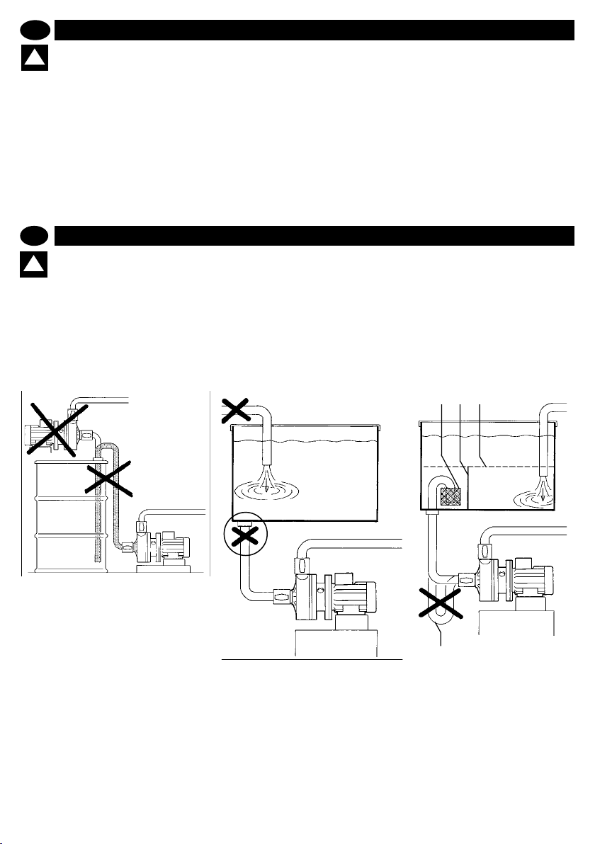
D- eventuali filtri di aspirazione
devono essere a cestello oppor-
tunamente sovradimensionati
(circa 3 volte la sezione di
aspirazione della pompa, per
evitare perdite di carico);
E- il pescante del tubo di aspira-
zione deve essere alloggiato
al’interno di idoneo stramazzo e
lontano da vortici, turbolenze e
scarichi liberi;
F- prevedere un dispositivo di
livello che determini l’arresto
del motore della pompa al di
sotto del livello minimo.
Il trasporto e posizionamento sono
così terminati.
A
D – any suction filters must be of
the basket-type and
D- eventuali filtri di aspirazione
devono essere a cestello oppor-
tunamente sovradimensionati
(circa 3 volte la sezione di
aspirazione della pompa, per
evitare perdite di carico);
E- il pescante del tubo di aspira-
zione deve essere alloggiato
al’interno di idoneo stramazzo e
lontano da vortici, turbolenze e
scarichi liberi;
F- prevedere un dispositivo di
livello che determini l’arresto
del motore della pompa al di
sotto del livello minimo.
Il trasporto e posizionamento sono
così terminati.
A
B
D – any suction filters must be of
the basket-type and
appropriately over-
dimensioned (approx 3 times
the pump suction diameter, to
avoid loss of pressure);
E – the dip tube of the suction pipe
must be housed inside the weir
and away from vortexes,
turbulence and open drains;
F – fit a level regulator device that
can halt the motor when the
pump is under the minimum
level.
Transportation and positioning are
now completed.
D
PRESCRIZIONI DI SICUREZZA
ACHTUNG: Der Betrieb der DM-Pumpen mit
!
schweren Schwebeteilchen oder der Trockenbe-
trieb verursacht das Schmelzen der Elemente in
schleifender Reibung und demzufolge möglicherweise zu
einem Brand, dessen müssen folgende Regeln eingehalten werden:
A- Die Pumpe ist nicht selbstfüllend und muss unter Anschlag aufgestellt werden;
B- Die Steigleitung des Ansaugrohrs der Pumpe muss
eine Form haben, dass Verstopfungen durch den Sog,
Schlick und schwere Stoffe vermieden wird, und sie muss
sich fern von Wirbeln oder Füllrohren des Behälters be-
nden;
GB
WARNING: DM pumps working with heavy elements
!
in suspension or in dry conditions can damage the
sealing as well as causing the fusion of sliding fric-
tion parts that may give rise to re, therefore the following
rules must be complied with:
A – the pump is not self priming and must be positioned
below head:
B – the dip tube of the suction pipe must be bent to avoid
clogging due to reux, grit and heavy matter, and it must
be kept away from vortexes or the tank lling pipes;
C- Das Ansaugrohr darf keine Siphone bilden;
D- Eventuelle Ansauglter müssen entsprechend überdimensionierte Korblter sein (etwa das 3-fache des
Ansaugquerschnitts der Pumpe), um Lastverluste zu vermeiden;
E- Die Steigleitung des Ansaugrohrs muss sich in einem
geeigneten Sturz und fern von Wirbeln, Turbulenzen und
freien Entladungen benden;
F- Es ist eine Pegelvorrichtung vorzusehen, die den
Stopp des Pumpenmotors unterhalb des Mindestpegels
auslöst.
Der Transport und die Aufstellung sind damit abgeschlossen.
C – the suction pipe must not create siphons;
D – any suction lters must be of the basket-type and
appropriately overdimensioned (approx 3 times
the pump suction diameter, to avoid loss of pressure);
E – the dip tube of the suction pipe must be housed
inside the weir and away from vortexes, turbulence and
open drains;
F – t a level regulator device that can halt the motor when
the pump is under the minimum level.
Transportation and positioning are now completed.
D E F
OK
livello minimo
min. level
A
19
B
C
info@debem.it
Page 20

D
ANSCHLUSS DES PRODUKTKREISLAUFS
PRESCRIZIONI DI SICUREZZA
Nachdem Sie die Positionierung durchgeführt haben, ist es
möglich, den Anschluss der Pumpe an den Produktkreislauf
anzuschließen. Der Vorgang wird im Folgenden beschrieben:
ACHTUNG: für die Verbindungen des Produktkreis
laufs an die Pumpe dürfen nur Anschlüsse mit zy-
!
lindrischem Rohrgewinde aus mit dem zu pumpenden Fluid und dem Baumaterial des Dämpfers kompatiblen
Material verwendet werden.
BSP: Pumpe aus PP = Anschluss PP
1. Installieren Sie auf dem Anschluss des Ablass- und Einlass
kollektors ein manuelles Kugelventil (mit vollem Durchgang) mit
dem gleichen Durchmesser des Anschlusses der Pumpe (nie
kleiner), um so das Auffangen des Fluids bei Leckagen und/
oder zukünftigen Wartungsarbeiten zu gewährleisten.
2. Sorgen Sie für die Installation der Muffen für die Befestigung
der Schläuche auf beiden manuellen Ventilen.
ACHTUNG: die Verbindungsleitungen an die Kol
lektoren der Pumpe müssen FLEXIBEL UND MIT
!
EINER STEIFEN SPIRALE VERSTÄRKT SEIN und
mit einem Durchmesser, der niemals kleiner als die Verbin
dungsstelle ist. Verwenden Sie für viskose Flüssigkeiten
Leitungen mit einem vergrößerten Durchmesser, beson
ders auf der Absaugung.
Der DIREKTE Anschluss an die Pumpe mit starren Me
tallrohren (an Pumpen aus Kunststoff und/oder mit konischem Gewinde) ist verboten, da dadurch starke Belastungen und/oder Vibrationen und ein Bruch der Kollektoren
und anderer Teile der Pumpe verursacht werden können.
Benutzen Sie immer exible Schläuche mit Anschlussstü
cken aus dem gleichen Material wie das der Pumpe (PP mit
PP, PVDF mit PVDF).
Ebenso ist die Verwendung von Gewindesicherungsstof
fen und/oder Teonpaste verboten. Der Installateur muss
bei der Montage auf die Zentrierung der Anschlüsse ach
-
-
-
-
-
-
-
-
-
ten, um Risse bzw. ein Nachgeben der Gewinde zu vermeiden.
Außerdem ist zu kontrollieren, ob nicht eventuell über
schüssiges PTFE-Band und ein übermäßiger Anzugsdruck
den Kollektor oder andere Teile der Pumpen zu stark be
lastet.
Besondere Beachtung ist Phänomenen von Spannungs
korrosion zu schenken. Das Material der Pumpe kann
durch die kombinierte Wirkung von Korrosion und der An
wendung einer Last verschleißen und dadurch der plötzliche und unerwartete Bruch der belasteten Teile verursacht
werden, insbesondere bei Temperaturgrenzwerten.
3. Sorgen Sie für den Anschluss der Einlass- und Ablassleitung.
Stellen Sie sicher, dass die Anschlussleitungen der Pumpe in
nen sauber sind und auf keinen Fall Verarbeitungsrückstände
enthalten.
4. Sorgen Sie für die Befestigung der Leitungen mit entspre
chenden Schellen.
ACHTUNG: stützen Sie ausreichend die Leitungen.
DIE LEITUNGEN MÜSSEN AUSREICHEND WIDER
!
STANDSFÄHIG SEIN, UM SICH NICHT UNTER DER
SAUGWIRKUNG ZU VERFORMEN UND DÜRFEN NIEMALS
IN IRGENDEINER WEISE AUF DER PUMPE LASTEN UND
UMGEKEHRT.
ACHTUNG: kontrollieren Sie, dass im behandelte
Fluid keine festen Partikel großer Form oder von
!
schädlicher Form vorhanden sind oder sein kön
nen und dass keine Einschränkungen am Einlass und/oder
Ablass der Pumpe vorhanden sind, um Kavitationserschei
nungen oder Kraftanstrengung des Elektromotors oder
Trockenlauf zu vermeiden.
Der Anschluss an den Produktkreislauf ist somit beendet.
-
-
-
-
-
-
-
-
-
PRODUCT CIRCUIT CONNECTION
GB
After having correctly positioned the plant, proceed with connecting the pump to the product circuit, as follows:
WARNING: To connect the pump only use connec
tions with cylindrical gas threads made with materials
!
compatible with the uid to be pumped and with the
pump materials. E.g: pump in PP = connections in PP
1. On the suction and delivery install a manual ball valve (fullbore) with a diameter equal to the connection to the pump (never
smaller), to ensure uid shut-off in case of leaks and/or future
maintenance.
2. Proceed with installation of pipe couplings for fastening the
exible pipes on to both of the manual valves.
WARNING: The connection pipes to the pump must
be FLEXIBLE, RIGID SPIRAL REINFORCED pipes
!
never with a smaller diameter than the connection of
the pump. For viscous uids, use pipes with an OVERSIZED
DIAMETER, particularly in suction.
Do not attach the pump DIRECTLY with rigid metal pipes (on
plastic pumps) and/or pipes with tapered thread, as they can
cause severe stress and/or vibrations and breakage of the
manifolds and other parts of the pump.
Always use exible joints with ttings made of the same
material of the pump (PP with PP, PVDF with PVDF)
Do not use threadlockers and/or Teon paste. The installer
must ensure that the ttings are centred during assembly to
prevent cracks and/or to prevent the threads from yielding.
Also check that any excess PTFE tape and excessive clamp
www.debem.it
ing pressure does not place stress on the manifold or other
parts of the pump.
Pay particular attention to stress corrosion cracking. The
pump material may deteriorate due to the combined action of
corrosion and application of a load, which may cause parts
subjected to stress to break suddenly and unexpectedly,
especially at low temperatures
3. Proceed to connect the product suction and delivery pipes to
their respective joints.
Check if the connection tubes to the pump are clean inside and
do no contain any working residue.
4. Proceed with fastening the pipes with appropriate metal rings.
WARNING: the pipes must be adequately suppor
ted; PIPES MUST BE STRONG ENOUGH NOT TO
!
DEFORM IN SUCTION AND MUST NEVER WEIGHT
THE PUMP DOWN OR VICEVERSA
WARNING: Check that the treated uid does not or
could not contain solid matters of a large size or with
!
a potentially damaging shape and that the intake
and/or delivery ports are not obstructed in order to avoid
cavitation or electric motor strain or dry operation.
The circuit connection is now completed.
-
20
-
Page 21

ATTENZIONE: i tubi di allaccia-
mento alla pompa devono
essere di tipo FLESSIBILE E RINFOR-
ZATO CON SPIRALE RIGIDA di diame-
tro mai inferiore all’attacco della
pompa. Per fluidi viscosi impiegare
tubi con DIAMETRO MAGGIORATO
specialmente sull’aspirazione.
L’allacciamento con tubi rigidi può
provocare forti vibrazioni.
3 Provvedere all’allacciamento del tubo
di aspirazione e mandata del prodotto
sui rispettivi attacchi.
!
ATTENZIONE: i tubi di allaccia-
mento alla pompa devono
essere di tipo FLESSIBILE E RINFOR-
ZATO CON SPIRALE RIGIDA di diame-
tro mai inferiore all’attacco della
pompa. Per fluidi viscosi impiegare
tubi con DIAMETRO MAGGIORATO
specialmente sull’aspirazione.
L’allacciamento con tubi rigidi può
provocare forti vibrazioni.
3 Provvedere all’allacciamento del tubo
di aspirazione e mandata del prodotto
sui rispettivi attacchi.
WARNING: The connection
pipes to the pump must be
FLEXIBLE, RIGID SPIRAL
REINFORCED pipes never with a
smaller diameter than the
connection of the pump. For viscous
fluids, use pipes with an OVERSIZED
DIAMETER, particularly in suction.
!
!
1
ATTENZIONE: i tubi di allaccia-
mento alla pompa devono
essere di tipo FLESSIBILE E RINFOR-
ZATO CON SPIRALE RIGIDA di diame-
tro mai inferiore all’attacco della
pompa. Per fluidi viscosi impiegare
tubi con DIAMETRO MAGGIORATO
specialmente sull’aspirazione.
L’allacciamento con tubi rigidi può
provocare forti vibrazioni.
3 Provvedere all’allacciamento del tubo
di aspirazione e mandata del prodotto
sui rispettivi attacchi.
WARNING: The connection
pipes to the pump must be
FLEXIBLE, RIGID SPIRAL
REINFORCED pipes never with a
smaller diameter than the
connection of the pump. For viscous
fluids, use pipes with an OVERSIZED
DIAMETER, particularly in suction.
Connection with rigid pipes can
cause strong vibrations.
3. Proceed to connect the product
suction and delivery pipes to their
respective joints.
!
!
1
3
AVVERTENZA: alimentare il
motore con tensioni inferiori o
superiori a quelle previste ( vedi
collegamenti ) causa il danneg-
giamento o addirittura la bruciatura
del motore.
5 Effettuare il collegamento del condut-
tore di messa a terra sull’apposito
morsetto e serrare a fondo la vite.
!
AVVERTENZA: alimentare il
motore con tensioni inferiori o
superiori a quelle previste ( vedi
collegamenti ) causa il danneg-
giamento o addirittura la bruciatura
del motore.
5 Effettuare il collegamento del condut-
tore di messa a terra sull’apposito
morsetto e serrare a fondo la vite.
ATTENZIONE: l’impianto elettri-
co a monte del motore deve
essere provvisto di efficiente linea
di messa a terra e di fusibili corret-
tamente dimensionati.
6 Provvedere alla messa a terra del
corpo pompa con un cavo di adeguata
1
!
AVVERTENZA: alimentare il
motore con tensioni inferiori o
superiori a quelle previste ( vedi
collegamenti ) causa il danneg-
giamento o addirittura la bruciatura
del motore.
5 Effettuare il collegamento del condut-
tore di messa a terra sull’apposito
morsetto e serrare a fondo la vite.
ATTENZIONE: l’impianto elettri-
co a monte del motore deve
essere provvisto di efficiente linea
di messa a terra e di fusibili corret-
tamente dimensionati.
6 Provvedere alla messa a terra del
corpo pompa con un cavo di adeguata
sezione per scaricare le correnti
statiche.
1
2
3
WARNING: supplying the motor
!
AVVERTENZA: alimentare il
motore con tensioni inferiori o
superiori a quelle previste ( vedi
collegamenti ) causa il danneg-
giamento o addirittura la bruciatura
del motore.
5 Effettuare il collegamento del condut-
tore di messa a terra sull’apposito
morsetto e serrare a fondo la vite.
ATTENZIONE: l’impianto elettri-
co a monte del motore deve
essere provvisto di efficiente linea
di messa a terra e di fusibili corret-
tamente dimensionati.
6 Provvedere alla messa a terra del
corpo pompa con un cavo di adeguata
sezione per scaricare le correnti
statiche.
1
2
3
4
!
WARNING: supplying the motor
with higher or lower voltage
than that required (see connection
) can damage or burn the motor.
5. Carry out the connection of the
earthing conductor to the
appropriate clamp and tightly fasten
the screw.
WARNING: the electrical plant
upstream from the motor must
!
AVVERTENZA: alimentare il
motore con tensioni inferiori o
superiori a quelle previste ( vedi
collegamenti ) causa il danneg-
giamento o addirittura la bruciatura
del motore.
5 Effettuare il collegamento del condut-
tore di messa a terra sull’apposito
morsetto e serrare a fondo la vite.
ATTENZIONE: l’impianto elettri-
co a monte del motore deve
essere provvisto di efficiente linea
di messa a terra e di fusibili corret-
tamente dimensionati.
6 Provvedere alla messa a terra del
corpo pompa con un cavo di adeguata
sezione per scaricare le correnti
statiche.
1
2
3
4
5
!
WARNING: supplying the motor
with higher or lower voltage
than that required (see connection
) can damage or burn the motor.
5. Carry out the connection of the
earthing conductor to the
appropriate clamp and tightly fasten
the screw.
WARNING: the electrical plant
upstream from the motor must
be adequately earthed and fitted with
correctly dimensioned fuses.
6. Equip the pump with an earthing
cable having a diameter adequate to
discharge static current.
I
GB
ATTENZIONE:
il personale addetto all’installazione, all’ispezio-
ne e alla manutenzione della pompa deve avere
adeguata preparazione tecnica unita a cognizioni
idonee al campo di applicazione (compatibilità ade-
guate in materia e rischi connessi ad eventuali reazio-
ni chimiche del prodotto da pompare).
INSTALLATORE/MANUTENTORE ELETTRICO:
questa qualifica presuppone una piena conoscenza e
comprensione delle informazioni contenute nel manuale
d’uso del costruttore, competenza tecnica specifica per
effettuare gli interventi di natura elettrica di: allacciamento,
manutenzione ordinaria e/o riparazione.
INTERVENTI STRAORDINARI: identifica gli interventi
riservati a tecnici del servizio di assistenza eseguiti
solo presso le officine del Costruttore.
WARNING
personnel responsible for pump installation,
inspection and maintenance shall possess a suitable
technical background along with knowledge of the
field of application (compatibility of materials and risks
associated with possible chemical reactions of the
product being pumped).
ELECTRICAL/FITTER AND MAINTENANCE
ENGINEER
!
!
STROMANSCHLUSS DES MOTORS UND ÜBERPRÜFUNG DER DREHUNG
D
PRESCRIZIONI DI SICUREZZA
Zur Ausführung des Stromanschlusses des Motors ist Folgendes notwendig:
ACHTUNG: Diese Arbeit muss von einem quali-
!
zierten und befugten Elektriker durchgeführt wer-
1
den, wobei am Versorgungskabel keine Spannung
anliegen darf.
1 Die Abdeckung der Klemmenleiste des Motors entfernen.
2 Die Kabelklemme lockern.
3 Das Stromkabel einführen, die Kabelklemme festziehen und
an die Leiter des Kabels passende Kabelschuhe mit Loch
heften.
4 Prüfen, ob die Spannungsdaten des Motors mit denen der
Stromversorgung kompatibel sind.
ELECTRICAL MOTOR CONNECTION AND ROTATION CHECK
GB
In order to carry out the electrical motor connection, proceed
as follows:
WARNING: this operation must be carried out by a
registered and qualied electrician, after discon-
!
necting power from the network.
1. Remove the cover of the motor terminal-box;
2. Loosen the cable-fastener;
3. Put the power cable in position, tighten the cable-fastener and
clamp the appropriate terminals to the cable conductors;
4. Check that the voltage of the motor is compatible with the
power supply
1
3
WARNHINWEIS: Wird der Motor mit niedrigeren
oder höheren Spannungen als vorgesehen versorgt (siehe λΔ-Anschlüsse), führt das zur Beschä-
digung oder sogar zum Durchbrennen des Motors.
5 Den Anschluss der Erdungsleitung an der dafür vorgesehenen Klemme ausführen und die Schraube ganz anziehen.
ACHTUNG: Die elektrische Anlage oberhalb des
!
Motors muss mit einer wirksamen Erdungsleitung
und mit korrekt dimensionierten Sicherungen ver-
sehen sein.
6 Die Erdung des Pumpenkörpers mit einem Kabel von adäquatem Querschnitt zur Ableitung der statischen Ströme
ausführen.
WARNING: supplying the motor with higher or lower
voltage than that required (see connection λΔ) can
damage or burn the motor.
5. Carry out the connection of the earthing conductor to the
appropriate clamp and tightly fasten the screw.
WARNING: the electrical plant upstream from the
!
motor must be adequately earthed and tted with
correctly dimensioned fuses.
6. Equip the pump with an earthing cable having a diameter
adequate to discharge static current.
2
3
5
21
4
4
6
info@debem.it
Page 22

8 ALLACCIAMENTO PER
MOTORE ASINCRONO TRIFASE
La disposizione delle barrette dei
morsetti dei motori trifase deve essere
variata.
8.1 CON ALIMENTAZIONE TENSIONE
INFERIORE
(schema a triangolo )
8 ALLACCIAMENTO PER
MOTORE ASINCRONO TRIFASE
La disposizione delle barrette dei
morsetti dei motori trifase deve essere
variata.
8.1 CON ALIMENTAZIONE TENSIONE
INFERIORE
(schema a triangolo )
L’alimentazione del motore con tensio-
ne inferiore (esempio: A = 230-400V
alimentazione a 230V; B =400-690V
alimentazione a 400V) deve essere
effettuata sui morsetti con le barrette
disposte secondo lo schema “a triango-
lo ”.
8.2 CON ALIMENTAZIONE TENSIONE
SUPERIORE (schema a stella )
7.1
7.3
8 ALLACCIAMENTO PER
MOTORE ASINCRONO TRIFASE
La disposizione delle barrette dei
morsetti dei motori trifase deve essere
variata.
8.1 CON ALIMENTAZIONE TENSIONE
INFERIORE
(schema a triangolo )
L’alimentazione del motore con tensio-
ne inferiore (esempio: A = 230-400V
alimentazione a 230V; B =400-690V
alimentazione a 400V) deve essere
effettuata sui morsetti con le barrette
disposte secondo lo schema “a triango-
lo ”.
8.2 CON ALIMENTAZIONE TENSIONE
SUPERIORE (schema a stella )
L’alimentazione del motore con tensio-
ne superiore (esempio: A = 230-400V
alimentazione a 400V; B =400-690V
alimentazione a 690V) deve essere
effettuata sui morsetti con le barrette
disposte secondo lo schema “a stella
”.
7.1
7.3
L N
7.2
MOTORE MONOFASE
SINGLE-PHASE MOTOR
8 ALLACCIAMENTO PER
MOTORE ASINCRONO TRIFASE
La disposizione delle barrette dei
morsetti dei motori trifase deve essere
variata.
8.1 CON ALIMENTAZIONE TENSIONE
INFERIORE
(schema a triangolo )
L’alimentazione del motore con tensio-
ne inferiore (esempio: A = 230-400V
alimentazione a 230V; B =400-690V
alimentazione a 400V) deve essere
effettuata sui morsetti con le barrette
disposte secondo lo schema “a triango-
lo ”.
8.2 CON ALIMENTAZIONE TENSIONE
SUPERIORE (schema a stella )
L’alimentazione del motore con tensio-
ne superiore (esempio: A = 230-400V
alimentazione a 400V; B =400-690V
alimentazione a 690V) deve essere
effettuata sui morsetti con le barrette
disposte secondo lo schema “a stella
”.
8 THREE-PHASE,
ASYNCHRONOUS MOTOR
CONNECTION
The arrangement of the clamp bars
must be changed.
8.1 WITH LOWER VOLTAGE POWER
(triangular diagram )
The power supply to a motor with lower
voltage (e.g. A = 23-400V power at
230V; B = 400-690V power at 400V)
must be carried out with the bars
7.1
7.3
L N
L N
7.2
MOTORE MONOFASE
SINGLE-PHASE MOTOR
8 ALLACCIAMENTO PER
MOTORE ASINCRONO TRIFASE
La disposizione delle barrette dei
morsetti dei motori trifase deve essere
variata.
8.1 CON ALIMENTAZIONE TENSIONE
INFERIORE
(schema a triangolo )
L’alimentazione del motore con tensio-
ne inferiore (esempio: A = 230-400V
alimentazione a 230V; B =400-690V
alimentazione a 400V) deve essere
effettuata sui morsetti con le barrette
disposte secondo lo schema “a triango-
lo ”.
8.2 CON ALIMENTAZIONE TENSIONE
SUPERIORE (schema a stella )
L’alimentazione del motore con tensio-
ne superiore (esempio: A = 230-400V
alimentazione a 400V; B =400-690V
alimentazione a 690V) deve essere
effettuata sui morsetti con le barrette
disposte secondo lo schema “a stella
”.
8 THREE-PHASE,
ASYNCHRONOUS MOTOR
CONNECTION
The arrangement of the clamp bars
must be changed.
8.1 WITH LOWER VOLTAGE POWER
(triangular diagram )
The power supply to a motor with lower
voltage (e.g. A = 23-400V power at
230V; B = 400-690V power at 400V)
must be carried out with the bars
arranged according to the triangular
diagram
8.2 WITH HIGHER VOLTAGE
POWER (Star diagram)
Power supply of a motor with higher
voltage (e.g. A = 239-400V power at
400V; B = 400-690V power at 690V)
must be carried out with the barrette
arranged according to the “star”
diagram
7.1
7.3
L N
L N
L1 L2 L3
7.2
MOTORE MONOFASE
SINGLE-PHASE MOTOR
u1 v1 w1
v2 u2 w2
MOTORE ASINCRONO TRIFASE
COLLEGAMENTO A TRIANGOLO
THREE-PHASE, ASYNCHRONOUS
MOTOR TRIANGULAR CONNEC.
A = 230V
B = 400V
8.1
D
PRESCRIZIONI DI SICUREZZA
7 ANSCHLUSS FÜR EINEN EINPHASIGEN MOTOR
Die Anordnung der Klemmenstifte bestimmt die Drehrichtung
des einphasigen Motors.
Für den Anschluss ist Folgendes notwendig:
7.1 Die Muttern der Klemmen wie in der Abbildung gezeigt
lockern.
7.2 Die Enden der beiden Leiter in die jeweiligen Kontakte
einschieben wie in der Abbildung gezeigt.
7.3 Die Zahnscheiben und die zugehörigen Muttern wieder
anbringen und ganz anziehen.
HINWEIS: Zum Umkehren der Drehrichtung des einphasigen Motors muss die Anordnung der Stifte geändert werden, danach sind die oben beschriebenen
Schritte für den Anschluss zu wiederholen.
GB
7 SINGLE-PHASE MOTOR CONNECTION
The arrangement of the clamps bars determines the singlephase motor rotation direction.
In order to carry out the connection, proceed as follows:
7.1 Loosen the clamps nuts as in the gure.
7.2 Insert the two conductors terminals on their respective
contacts as in gure.
7.3 Reassemble the washers and respective nuts and fasten
tightly.
www.debem.it
NOTE: In order to invert the single-phase motor rotation
direction, change the arrangement of the bars and repeat
the operations described above for the connection.
MOTORE ASINCRONO TRIFASE
COLLEGAMENTO A TRIANGOLO
7.1
EINPHASIGER MOTOR
DREICKSANSCHLUSS
THREE-PHASE, ASYNCHRONOUS
MOTOR TRIANGULAR CONNEC.
L1 L2 L3
u1 v1 w1
v2 u2 w2
A = 230V
B = 400V
MOTORE MONOFASE
7.3
SINGLE-PHASE MOTOR
8 ANSCHLUSS FÜR EINEN ASYNCHRONEN DREIPHASIGEN MOTOR
Die Anordnung der Stifte der Klemmen von dreiphasigen Motoren muss variiert werden.
8.1 MIT NIEDRIGERER SPANNUNGSVERSORGUNG (Drei-
eckschema Δ)
Die Versorgung des Motors mit einer niedrigeren Spannung
(z. B.: A = 230-400 V
Versorgung mit 230 V; B =400-690 V
Versorgung mit 400 V) muss an den Klemmen mit der Anord-
nung der Stifte nach dem „Dreieckschema Δ” erfolgen.
8.2 BEI VERSORGUNG MIT EINER HÖHEREN SPANNUNG
(Sternschema Y)
Die Versorgung des Motors mit einer höheren Spannung (z.
B.: A = 230-400 V
Versorgung mit 400 V; B =400-690 V
Versorgung mit 690 V) muss an den Klemmen mit der Anordnung der Stifte nach dem „Sternschema Y” erfolgen.
8 THREE-PHASE, ASYNCHRONOUS MOTOR CONNECTION
The arrangement of the clamp bars must be changed.
8.1 WITH LOWER VOLTAGE POWER (triangular diagram Δ )
The power supply to a motor with lower voltage (e.g. A = 23400V power at 230V; B = 400-690V power at 400V) must be
carried out with the bars arranged according to the triangular
diagram Δ.
8.2 WITH HIGHER VOLTAGE POWER (Star diagram Y)
Power supply of a motor with higher voltage (e.g. A = 239-400V
power at 400V; B = 400-690V power at 690V) must be carried
out with the barrette arranged according to the “star” diagram Y.
L N
L N
7.2
ASYNCHRONER DREIPHASIGER MOTOR
MOTORE ASINCRONO TRIFASE
STERNANSCHLUSS
COLLEGAMENTO A STELLA
THREE-PHASE, ASYNCHRONOUS
MOTOR STAR CONNECTION
L1 L2 L3
u1 v1 w1
v2 u2 w2
A = 400V
8.1
B = 690V
8.2
22
Page 23

10 Invasare la pompa ed aprire le
valvole manuali del condotto di
aspirazione e mandata.
11 Avviare per un breve istante il
motore della pompa e verificare
visivamente attraverso la griglia della
ventola il senso di rotazione.
12 Se il senso di rotazione è corretto
(orario lato ventola motore) coincide-
rà con l’etichetta apposta e l’opera-
zione sarà terminata.
8.4Allentare i dadi dei morsetti del
motore e disporre le barrette secon-
do il tipo di alimentazione e di
avviamento desiderato.
8.5Inserire i terminali dei conduttori sui
rispettivi morsetti come mostrato in
figura.
8.6Rimontare le ranelle ed i dadi e
serrarli a fondo.
u2 v1
w2 w1
AVVIO/START-UP = KM1 + KM2 (STELLA/STAR
REGIME = KM1 + KM3 (TRIANGOLO )
8.4Allentare i dadi dei morsetti del
motore e disporre le barrette secon-
do il tipo di alimentazione e di
avviamento desiderato.
8.5Inserire i terminali dei conduttori sui
rispettivi morsetti come mostrato in
figura.
8.6Rimontare le ranelle ed i dadi e
serrarli a fondo.
N
R1
S1
T1
KM1 KM3 KM2
A
v2 u1
u2 v1
w2 w1
T
)
M
3 ~
8.4
8.6
8.4Allentare i dadi dei morsetti del
motore e disporre le barrette secon-
do il tipo di alimentazione e di
avviamento desiderato.
8.5Inserire i terminali dei conduttori sui
rispettivi morsetti come mostrato in
figura.
8.6Rimontare le ranelle ed i dadi e
serrarli a fondo.
N
R1
S1
T1
KM1 KM3 KM2
A
v2 u1
u2 v1
w2 w1
T
)
M
3 ~
8.4 Loosen the motor terminal nuts
and arrange the bars according to
the desired type of power and start-
up.
8.5 Insert the conductor terminals on
to the respective clamps as shown
in the figure.
8.6 Re-assemble the washer and nuts
and tighten them.
8.4
8.6
u1 v1 w1
v2 u2 w2
8.4Allentare i dadi dei morsetti del
motore e disporre le barrette secon-
do il tipo di alimentazione e di
avviamento desiderato.
8.5Inserire i terminali dei conduttori sui
rispettivi morsetti come mostrato in
figura.
8.6Rimontare le ranelle ed i dadi e
serrarli a fondo.
N
R1
S1
T1
KM1 KM3 KM2
A
v2 u1
u2 v1
w2 w1
T
)
M
3 ~
KM1
KM2
8.4 Loosen the motor terminal nuts
and arrange the bars according to
the desired type of power and start-
up.
8.5 Insert the conductor terminals on
to the respective clamps as shown
in the figure.
8.6 Re-assemble the washer and nuts
and tighten them.
10 Invasare la pompa ed aprire le
valvole manuali del condotto di
aspirazione e mandata.
11 Avviare per un breve istante il
motore della pompa e verificare
visivamente attraverso la griglia della
ventola il senso di rotazione.
12 Se il senso di rotazione è corretto
(orario lato ventola motore) coincide-
rà con l’etichetta apposta e l’opera-
zione sarà terminata.
L1 L2 L3
u1 v1 w1
v2 u2 w2
L1 L3 L2
u1 v1 w1
v2 u2 w2
D
PRESCRIZIONI DI SICUREZZA
8.3 MIT STROMVERSORGUNG FÜR STERN-/
DREICKS-EINSCHALTUNG
Die Stern-/Dreiecks-Einschaltung muss für Stromstärken über
4 KW (5,5 PS) und/oder häuge Einschaltungen (mehr als 5
Einschaltungen pro Tag) oder für Einschaltungen für nur wenige Minuten benutzt werden, sowie um den Stromverbrauch
während des Einschaltvorgangs in Grenzen zu halten und damit den Motor zu schützen.
Diese Verwendung wird mit geeigneten Apparaturen erreicht,
indem man die Stifte der Klemmenleiste des Motors entfernt
und den Anschluss der Stromkabel wir auf dem Schaltplan
gezeigt durchführt.
Die Schaltung des Motors für Stern-/Dreiecks-Einschaltung
muss realisiert werden, indem die Stromversorgung mit der
niedrigeren Netzspannung erfolgt.
Beispiel:
• A = 230-400V Einspeisung von 230V
• B = 400-690V Einspeisung von 400V
8.4 Die Klemmenmuttern des Motors lockern und die Stifte je
GB
8.3 WITH POWER FOR STAR/TRIANGLE START-UP
Star/triangle start-up must be used for power higher than 4Kw
(5,5HP) and/or frequent start-ups (more than 5 a day) or when
operated for periods lasting just a few minutes, as well as to
contain absorption during start-ups and to safeguard the motor.
This type of usage is achieved with appropriate equipment,
abolishing the terminal box bars and carrying out power cable
connection as in the diagram.
The star/triangle motor start-up must be carried out with the
lowest mains voltage.
Example:
• A = 230-400V power at 230V
• B = 400-690V power at 400V
8.4 Loosen the motor terminal nuts and arrange the bars according to the desired type of power and startup.
8.5 Insert the conductor terminals on to the respective clamps
N
R1
S1
T1
KM1 KM3 KM2
T
M
3 ~
v2 u1
A
KM1
u1 v1 w1
v2 u2 w2
)
KM2
nach Art der Einspeisung und der gewünschten Einschaltung
anordnen.
8.5 Die Leiterenden in die jeweiligen Klemmen einschieben
wie auf der Abbildung gezeigt.
8.6 Die Zahnscheiben und die zugehörigen Muttern wieder
anbringen und ganz anziehen.
HINWEIS: Zum Umkehren der Drehrichtung des
dreiphasigen Motors müssen zwei der drei Pha-
sen (L1, L2 und L3) vertauscht werden, oder der
Anschluss für STERN-/DREIECK-Einschaltung (u1, v1, w1
und u2, v2 und w2) vorgenommen werden.
WARNHINWEIS: Jedweden Fremdkörper aus der
Kontaktdose des Motors entfernen und sich verge-
wissern, dass die Enden bzw. die Leiter einander
nicht berühren und keinen Kurzschluss verursachen.
9 Die elektrische Kontaktdose des Motors mit den zugehörigen Schrauben wieder verschließen.
as shown in the gure.
8.6 Re-assemble the washer and nuts and tighten them.
NOTE: In order to invert the threephase motor rotation,
you must invert two out of the three phases L1, L2 and
L3 - or - for the STAR/ TRIANGLE start-up (u1, v1, w1
and u2, v2 and w2).
WARNING: Remove any foreign matter from the mo-
tor contacts
box and ensure that the terminals and/ or conductors
do not touch and do not cause shorts.
9 Close the motor contact box with its screws.
WARNING: never start the pump up when dry, not
!
even shortly; beside permanent damage to the seal-
ing, this could cause re and uid leakage.
23
KM1
u1 v1 w1
v2 u2 w2
KM3
8.4
8.6
L1 L2 L3
u1 v1 w1
v2 u2 w2
L1 L3 L2
u1 v1 w1
v2 u2 w2
info@debem.it
9
Page 24

L’allacciamento elettrico e la verifi-
ca del senso di rotazione sono così
terminate.
L’allacciamento elettrico e la verifi-
ca del senso di rotazione sono così
terminate.
7 ALLACCIAMENTO PER
MOTORE MONOFASE
8 ALLACCIAMENTO PER
MOTORE TRIFASE
24
Power connection and rotation
direction checks are now completed.
7 SINGLE-PHASE
MOTOR
CONNECTION
8 THREE-PHASE
ASYNCHRONOUS
MOTOR
CONNECTION
D
PRESCRIZIONI DI SICUREZZA
ACHTUNG: Nie die Pumpe trocken in Gang setzen, auch nicht für kurze Augenblicke, denn es
!
besteht die Möglichkeit eines Brandausbruchs
und dass Flüssigkeit austritt.
10 Die Pumpe eintauchen und die manuellen Ventile der Ansaug- und der Förderleitung öffnen.
11 Den Pumpenmotor kurz starten und eine Sichtkontrolle der
Drehrichtung durch das Lüftungsgitter durchführen.
12 Wenn die Drehrichtung korrekt ist (im Uhrzeigersinn am
Flügelrad des Motors), stimmt sie mit der angebrachten Etikette überein und die Arbeit ist damit abgeschlossen.
13 Wenn die Drehrichtung in Gegenrichtung ist, muss die Versorgungsspannung oberhalb getrennt und wie in Paragraph
“7 ANSCHLUSS FÜR EINPHASIGEN MOTOR” oder wie in “8
ANSCHLUSS FÜR DREIPHASIGEN MOTOR” vorgegangen
werden, um die Drehrichtung des Motors umzukehren. Danach sind die Überprüfungen durchzuführen, die von Punkt 9
bis Punkt 12 beschrieben sind.
14 Die Pumpe und die Ansaug- sowie die Förderleitung immer
vor möglichen zufälligen Stößen durch in Bewegung bendliche Gegenstände oder anstoßende Materialien schützen, die
sie beschädigen und/oder bei Kontakt reagieren können.
15 Die Umgebung und die Personen durch Installation einer
Schutzabdeckung schützen: Im Fall von zufälligen Defekten
der Pumpe müssen die Flüssigkeiten, um sie bei einem Austritt des Produkts rückzuhalten und zu sammeln, in einen geschützten und sicheren Bereich abgeleitet werden.
Der Stromanschluss und die Überprüfung der Drehrichtung
sind damit abgeschlossen.
GB
10 Flood the pump and open the manual valves of the suction
and delivery conduit.
11 Briey start-up the pump motor and visually check the
rotation direction through the fan grate.
12 If the rotation direction is correct (clockwise on the fan side
of the motor) it will coincide with the indications on the plate
and the operation will be completed
13 If the rotation direction is wrong, disconnect the power
supply from the motor and proceed as described in paragraph
7: CONNECTION OF SINGLE-PHASE MOTOR or in
paragraph 8: CONNECTION OF THREE-PHASE MOTOR, in
order to invert the motor rotation direction; afterwards repeat
the checks in point 9 to 12.
14. Protect the pump and suction and delivery pipes from
possible, accidental knocks from moving vehicles or materials
that could damage it and/or react when in contact with it.
15 Protect the environment and people by installing a shield;
discharge and collect any uid leakage due to accidental
breakdown of the pump, conveying it to a safe and protected
area.
Power connection and rotation direction checks are now
completed.
7 ALLACCIAMENTO PER
MOTORE MONOFASE
7 SINGLE-PHASE
MOTOR
CONNECTION
15
14
24
8 ALLACCIAMENTO PER
MOTORE TRIFASE
8 THREE-PHASE
ASYNCHRONOUS
MOTOR
CONNECTION
www.debem.it
24
Page 25

INBETRIEBNAHME
D
PRESCRIZIONI DI SICUREZZA
Der Installateur/Benutzer muss unter Bezugnahme auf die
Planungsbedingungen der Pumpe immer Materialien einsetzen, die mit der gepumpten Flüssigkeit kompatibel sind.
ACHTUNG: Die Benutzung der Pumpe mit Flüssig-
!
keiten, die nicht mit den Materialien ihrer Bautei-
le kompatibel sind, oder in einer Umgebung, wo
nicht kompatible Flüssigkeiten vorhanden sind, ist verboten.
Für die Inbetriebnahme der Pumpe ist folgend vorzugehen:
1. Überprüfen, ob das Ansaug- und das Förderrohr für das
Produkt korrekt angeschlossen sind.
ACHTUNG: Der Trockenbetrieb der DM-Pumpen
!
ruft ein Schmelzen der Bauteile durch schleifende
Reibung und in der Folge möglicherweise einen
Brand hervor.
2. Die manuellen Kugelventile der Ansaug- und der Förderleitung für die Flüssigkeit öffnen.
3. Die Pumpe eintauchen, sodass darüber mindestens 0,5 m
Flüssigkeit sind.
4. Den Motor mittels der entsprechenden Steuerungen starten.
5. Zum Stoppen der Pumpe ausschließlich die Steuerungen
zum Stoppen des Elektromotors der Pumpe betätigen.
START-UP
GB
The installer/operator must always use material compatible with
the pumped liquid and in line with the pump design.
WARNING: it is forbidden to use liquids that are
incompatible with the materials of the pump
!
components or in an environment where there are
incompatible uids.
In order to start-up the pump, proceed as follows:
1 Check that the suction and delivery pipes are correctly
connected.
WARNING: Dry operation of DM pumps, causes
the fusion of sliding friction elements and conse-
!
quently re is also possible.
2. Open the manual ball valves of the suction and delivery
uid pipes;
3. Flood the pump to least 0,5 metres above it;
4. Start the motor with the appropriate controls.
5. To stop the pump, only use the stop controls of the pump’s
electric motor.
WARNING: never stop a working pump by closing
!
the uid circuit suction and/or delivery ball valves:
ACHTUNG: Die laufende Pumpe nie mittels Schließung der Kugelventile der Ansaug- und/oder der
!
Förderleitung des Flüssigkeitskreislaufs stoppen.
ACHTUNG: Überprüfen, ob während des Betriebs keine
anormale Geräuschentwicklung auftritt.
Sollte das der Fall sein, die Pumpe sofort stoppen,
!
um die Ursachen festzustellen und zu beseitigen.
ACHTUNG: Kontrollieren, ob in der geförderten Flüssig-
keit keine Luft- oder Gasblasen vorhanden sind.
Sollte das der Fall sein, muss der Betrieb der
!
Pumpe sofort gestoppt und die Ursache behoben
werden.
ACHTUNG: An der Ansaugleitung keine Filter in-
!
stallieren, die Lastverluste verursachen können.
6 Nach den ersten beiden Betriebsstunden ist die Pumpe korrekt zu stoppen und Folgendes durchzuführen:
A- Prüfen, ob alle Schrauben der Pumpe fest angezogen
sind;
B- die Produktleitungen überprüfen.
Die von der Maschine abgegebenen Schallpegel haben folgende Werte:
Der Schalldruckpegel der gewichteten Emission A liegt an den
Arbeitsplätzen unter 75 dB.
WARNING: check that there is no anomalous noise
while the pump is working. If so, immediately stop
!
the pump, check and eliminate the cause.
WARNING: check that there are no air or gas bub-
bles in the output uid. If so, immediately stop the
!
pump, check and eliminate the cause.
WARNING: do not install lters on the suction pipe
!
that may cause a loss of pressure.
6. After the pump rst two working hours, and after correctly
stopping it, check:
A. check the tightening of all bolts;
B. check the product pipes.
The noise levels of the machine correspond to:
• The sound pressure level of the A weighted emission, in the
working place, is less than 75 dB.
25
info@debem.it
Page 26
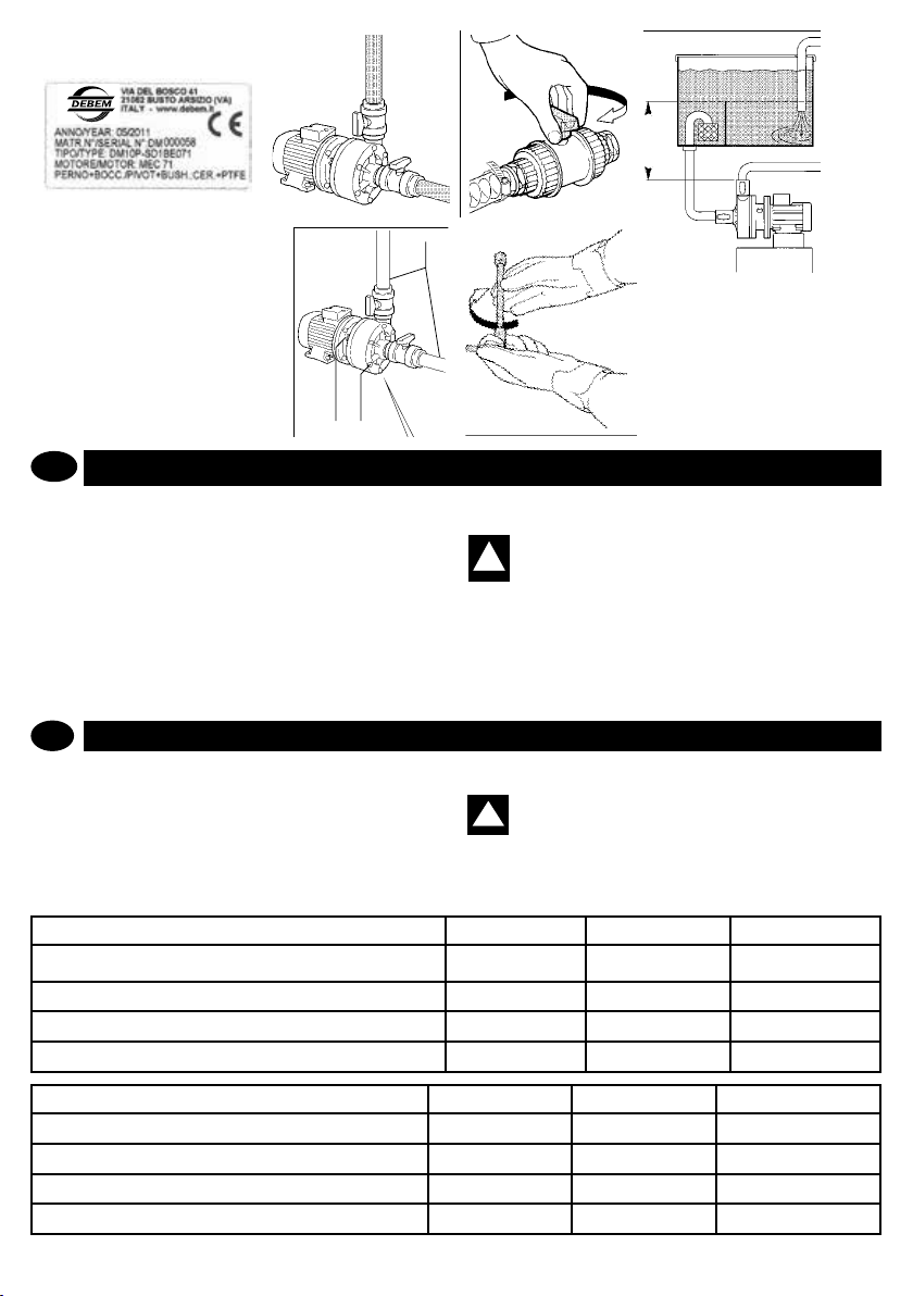
2 Aprire le valvole a sfera manuali delle
tubazioni del fluido di aspirazione e
mandata.
3 Invasare la pompa di almeno 0,5 m al
di sopra della stessa.
4 Avviare il motore mediante gli apposi-
ti comandi.
5 Per l’arresto della pompa agire esclu-
sivamente sui comandi di arresto del
motore elettrico della pompa.
ATTENZIONE: non arrestare mai
la pompa in funzione mediante
la chiusura delle valvole a sfera di
aspirazione e/o mandata del circuito
del fluido: PERICOLO DI STALLO
DELLA POMPA E/O DI INCENDIO
DOVUTO ALLA FUSIONE DELLA
TENUTA PER FUNZIONAMENTO A
SECCO.
OUT
!
2 Aprire le valvole a sfera manuali delle
tubazioni del fluido di aspirazione e
mandata.
3 Invasare la pompa di almeno 0,5 m al
di sopra della stessa.
4 Avviare il motore mediante gli apposi-
ti comandi.
5 Per l’arresto della pompa agire esclu-
sivamente sui comandi di arresto del
motore elettrico della pompa.
ATTENZIONE: non arrestare mai
la pompa in funzione mediante
la chiusura delle valvole a sfera di
aspirazione e/o mandata del circuito
del fluido: PERICOLO DI STALLO
DELLA POMPA E/O DI INCENDIO
DOVUTO ALLA FUSIONE DELLA
TENUTA PER FUNZIONAMENTO A
SECCO.
2. Open the manual ball valves of the
suction and delivery fluid pipes;
3. Flood the pump to least 0,5 metres
above it;
4. Start the motor with the appropriate
controls.
5. To stop the pump, only use the stop
controls of the pump’s electric
motor.
WARNING: never stop a working
pump by closing the fluid
circuit suction and/or delivery ball
valves: DANGER OF PUMP
STALLING AND/OR FIRE DUE TO
SEAL BURN-OUT CAUSED BY DRY
OPERATION.
IN
OUT
1
2
!
!
6 Dopo le prime due ore di funziona-
mento della pompa, e dopo averla
correttamente arrestata, bisogna:
A- verificare visivamente, attraverso il
foro di ispezione della campana,
che non vi siano trafilamenti dalla
tenuta;
B- verificare il serraggio di tutti i
bulloni della pompa;
C- verificare i condotti del prodotto.
6 After the pump first two working
hours, and after correctly stopping
it, check:
A B
C
2 Aprire le valvole a sfera manuali delle
tubazioni del fluido di aspirazione e
mandata.
3 Invasare la pompa di almeno 0,5 m al
di sopra della stessa.
4 Avviare il motore mediante gli apposi-
ti comandi.
5 Per l’arresto della pompa agire esclu-
sivamente sui comandi di arresto del
motore elettrico della pompa.
ATTENZIONE: non arrestare mai
la pompa in funzione mediante
la chiusura delle valvole a sfera di
aspirazione e/o mandata del circuito
del fluido: PERICOLO DI STALLO
DELLA POMPA E/O DI INCENDIO
DOVUTO ALLA FUSIONE DELLA
TENUTA PER FUNZIONAMENTO A
SECCO.
2. Open the manual ball valves of the
suction and delivery fluid pipes;
3. Flood the pump to least 0,5 metres
above it;
4. Start the motor with the appropriate
controls.
IN
OUT
1
!
min
IN
0,5 m
1
C
A B
ZEITPLAN UND ORDENTLICHE WARTUNG
D
PRESCRIZIONI DI SICUREZZA
Zur Gewährleistung der Leistungen und eines sicheren Einsatzes erfordern die DM-Pumpen ordentliche Wartungsarbeiten,
die während der gesamten Nutzungsdauer der Pumpe in Einhaltung des in der Tabelle angegebenen Zeitplans durchgeführt
werden müssen.
Der in der Tabelle für ordentliche Wartungsarbeiten angegebene
Zeitplan bezieht sich auf einen Einsatz unter Normalbedingungen. Werden DM-Pumpen unter schwierigeren Bedingungen
eingesetzt, erfordern sie Eingriffe in kürzeren Zeitabständen
mit einer Herabstufung der angegebenen Eingriffshäugen
GB
STANDARD MAINTENANCE TIME-SCHEDULE
In order to guarantee performance and safe use, DM pumps
need standard maintenance operations throughout their life
span and in accordance to the time-schedule detailed in the
table.
The time schedule for routine maintenance shown in the table
refers to standard use and working conditions; more demanding
working conditions require more frequent operations, with a
PRÜFUNG UND/ODER EINGRIFF
KONTROLLE VON DREHENDEN TEILEN
INNENREINIGUNG DER PUMPE (Laufrad und Leitungen)
AUSTAUSCHEN DER STATISCHEN DICHTUNGEN
AUSTAUSCHEN DER DREHENDEN TEILE
CHECK AND/OR OPERATION every 1000 hours every 5000 hours every 10000 hours
CHECK FOR ROTARY SEAL LEAKS
CLEANING INSIDE PUMP (impeller and pipes)
STATIC SEAL REPLACEMENT
ROTARY SEAL REPLACEMENT
www.debem.it
von 30 % bis 50 %.
ACHTUNG: Fehlende Wartung und/oder fehlende
Einhaltung der Eingriffszeiten für die ordentliche
!
Wartung führt nicht nur zum Verfall der Garantiebedingungen, sondern kann auch verursachen, dass es zu
einer übermäßigen Abnutzung und zu einer Beschädigung
der inneren Organe der Pumpe und/oder des Motors kommt
und Gefahrensituationen auftreten, für die der Hersteller
nicht haftbar gemacht werden kann.
30% to 50% more frequent interventions than that indicated.
WARNING: failure to proceed and/or comply with
!
standard maintenance and/or its time schedule,
renders the warranty null and can excessively
wear and damage the internal parts of the pump and/or the
motor, as well as create hazardous situations, for which
the manufacturer is not to be held liable.
Alle 1000 Stunden Alle 5000 Stunden Alle 10000 Stunden
●
●
26
2
3
B
●
●
●
●
●
●
Page 27

WARTUNG DES PRODUKTKREISLAUFS
C- chiudere le valvole di intercet-
tazione (aspirazione mandata)
D-sezionare e mettere in sicurez-
za l’alimentazione elettrica del
motore della pompa;
E-munirsi di idonee protezioni
individuali prima di intervenire
(maschere facciali, guanti,
scarpe chiuse, grembiuli ecc.):
1
1
2
1
2
3
DN
A
C
C- chiudere le valvole di intercet-
tazione (aspirazione mandata)
D-sezionare e mettere in sicurez-
za l’alimentazione elettrica del
motore della pompa;
E-munirsi di idonee protezioni
individuali prima di intervenire
(maschere facciali, guanti,
scarpe chiuse, grembiuli ecc.):
PERICOLO DI EIEZIONE DEL
FLUIDO.
C. close the ON-OFF valve
A
C
B
C- chiudere le valvole di intercet-
tazione (aspirazione mandata)
D-sezionare e mettere in sicurez-
za l’alimentazione elettrica del
motore della pompa;
E-munirsi di idonee protezioni
individuali prima di intervenire
(maschere facciali, guanti,
scarpe chiuse, grembiuli ecc.):
PERICOLO DI EIEZIONE DEL
FLUIDO.
C. close the ON-OFF valve
(delivery/suction)
D. section the power supply to the
pump motor and ensure it is
safe;
E. wear the appropriate protective
clothing before any operation
(mask, gloves, closed shoes,
aprons, etc.): FLUID EJECTION
HAZARD.
A
C
B
D
C- chiudere le valvole di intercet-
tazione (aspirazione mandata)
D-sezionare e mettere in sicurez-
za l’alimentazione elettrica del
motore della pompa;
E-munirsi di idonee protezioni
individuali prima di intervenire
(maschere facciali, guanti,
scarpe chiuse, grembiuli ecc.):
PERICOLO DI EIEZIONE DEL
FLUIDO.
C. close the ON-OFF valve
(delivery/suction)
D. section the power supply to the
pump motor and ensure it is
safe;
E. wear the appropriate protective
clothing before any operation
(mask, gloves, closed shoes,
aprons, etc.): FLUID EJECTION
HAZARD.
D
PRESCRIZIONI DI SICUREZZA
ACHTUNG: Vor Arbeiten an der Pumpe bzw. vor
der Durchführung von Wartungs- oder Reparatur-
!
arbeiten ist Folgendes notwendig:
A - Das Produkt ablassen, das gepumpt wird, und die Produktsperrventile (Förderleitung) schließen.
B - Eine geeignete und nicht entammbare Reinigungsüssigkeit zirkulieren lassen, danach das Ventil an der Förderleitung
öffnen und dieses entleeren. Den Pumpenmotor stoppen.
C - Die Sperrventile (Ansaug- und Förderleitung) schließen.
D - Die Stromversorgung des Elektromotors der Pumpe trennen und in Sicherheitszustand bringen.
E - Anlegen von geeigneter Schutzausrüstung vor der Arbeit (Gesichtsmasken, Handschuhe, geschlossene Schuhe,
Schürzen usw.): ES BESTEHT GEFAHR, DASS DIE FLÜSSIGKEIT HERAUSGESCHLEUDERT WIRD.
ACHTUNG: Die Pumpe ausschließlich mit einem
mit geeigneten Reinigungsmitteln befeuchteten
!
Tuch reinigen.
1. Den Ansaug- und den Förderschlauch der Flüssigkeit von
MAINTENANCE FOR THE PRODUCT CIRCUIT
GB
WARNING: before any operation on the pump and/
or before any maintenance or repair operation,
!
proceed as follows:
A. discharge the product being pumped and close the product
intercepting valve (delivery);
B. run an appropriate, nonammable washing uid through
the circuit, after which discharge it by opening the delivery
valve; stop the pump motor;
C. close the ON-OFF valve (delivery/suction)
D. section the power supply to the pump motor and ensure it is
safe;
E. wear the appropriate protective clothing before any operation (mask, gloves, closed shoes, aprons, etc.): FLUID EJECTION HAZARD.
WARNING: To clean the pump, only use a clean
!
cloth, moistened with an appropriate detergent:
A
C
1
der Pumpe abklemmen.
2. Das Stromkabel des Motors abklemmen.
3. Die Pumpe vom Installationsort abmontieren und mit geeigneten Hebewerkzeugen von dort entfernen.
HINWEIS: Ziehen Sie die entsprechende Ersatzteiltabelle für die Arbeitsabläufe zum Abmontieren
und erneuten Montieren der Pumpe und für die
nachfolgend beschriebenen Eingriffe heran.
Vor Arbeiten an der Pumpe bzw. vor der Durchführung von
Wartungs- oder Reparaturarbeiten ist Folgendes notwendig:
• Mindestens zehn Minuten warten, bis die Pumpe abgekühlt
ist;
• Zur Ausführung der notwendigen Arbeiten Schutzhandschuhe und alle übrigen geeignete persönliche Schutzausrüstung
(Gesichtsmaske, Handschuhe, geschlossene Schuhe usw.)
anlegen: Es besteht Gefahr eines Herausspritzens von Flüssigkeit unter Druck und von Verbrühungen.
1. Disconnect the uid suction and delivery pipes of the pump;
2. Disconnect the electrical power supply cable from the motor;
3. Proceed with disassembling and remove the pump from the
installation area, using appropriate lifting equipment.
NOTE: For the pump assembly and disassembly sequence of the operations hereafter described consult
the relevant, spare parts table.
Before intervening on the pump and/or before carrying out
maintenance or repair operations, you must
• Wait for the pump to cool down for at least fteen minutes
• Perform the necessary operations while wearing protection
gloves and any other appropriate personal protection
equipment (face masks, gloves, closed shoes, etc.): Danger
of burning and ejection of liquid under pressure.
E
D
1
4
2
3
B
SOP
SOP
1
2
3
4
5
6
7
8
9
01
11
21
31
41
51
61
71
81
91
02
12
22
32
42
52
62
72
2
3
27
MB PUMP
POMPA MB
GB
I
TL 110-120-130
TL 110-120-130
5
6
11
9
16
5
7
8
10
at t ehc i tE
anretnaletiV
anai pal l ednoR
er o t oM
onai ponarG
oreb l A
al occ obel a i zna t s iD
acimarecnial oc coB
ota i gna l fodaD
ota i gna l fodaD
etna r i goni ar ta t t eugn i L
etiV
anai pal l ednoR
anre t naL
at une ta t ropa i gna l F
orbba l aat uneT
enoiz i nr auG
et na r i genoi z i n r auG
et na r i goi ggacco l bodaD
enoiz net t aat t ehc i tE
ero i r e t sopai gna l F
apmopop r oceno i z i n ra uG
enoiz i nr auG
et na r i G
apmopop r oC
anai pal l ednoR
apmopop r ocet i V
22
23
24
12
13
15
16
17
21
ENOI Z I RCS E
25
18
26
19
27
20
àt.Q
OI TP I RCS ED
yt.Q
lebaL
wercseldnipS
rehsawtalF
ro t oM
tunburg-ta l F
t f a hS
recapsgnihsuB
ginihsucimareC
tundegnal F
tundegnal F
yek-p i lgn i nr uT
wer c S
rehsawtalF
rennatS
egnal fgn i laeS
laespiL
te k s aG
teksagr e l l epmI
tungnikco l r e l l epmI
leba lgn i nr aW
egnal f r aeR
teksaggnisacpmuP
te k s aG
re l le pm I
gnisacpmuP
rehsawtalF
we r c sg n i s a cpmuP
48
info@debem.it
Page 28

ÖFFNEN DER PUMPE UND INNENREINIGUNG
AVVERTENZA: verificare che non
vi siano depositi di alcun genere
all’interno della pompa in caso contrario
provvedere alla rimozione.
A4 Verificare lo stato delle guarnizioni e
se necessario provvedere alla
sostituzione con ricambi originali
dello stesso tipo.
A5 Provvedere al rimontaggio operando
nell’ordine inverso ed eseguire un
tiraggio uniforme dei bulloni di
fissaggio del guscio.
La pulizia e/o sostituzione della girante è
così terminata ed è possibile eseguire il
riposizionamento e gli allacciamenti
della pompa come trattato nei preceden-
ti Capitoli
MANUTENZIONE DEL
CIRCUITO PRODOTTO
31
A1
WARNING: check that there is
no sediment inside the pump, if
MAINTENANCE FOR
THE PRODUCT CIRCUIT
I
GB
48
POMPA MB
TL 110-120-130
1
4
2
3
5
6
11
5
7
8
10
9
16
22
23
24
12
13
15
16
17
21
25
26
27
18
19
20
SOP
SOP
ENOIZI RCSEDNOITPI RCSED
àt.Q
yt.Q
1
2
3
4
5
6
7
8
9
01
11
21
31
41
51
61
71
81
91
02
12
22
32
42
52
62
72
attehci tE
anretnaletiV
anaipall ednoR
erot oM
onaiponarG
oreblA
aloccobelai znatsiD
acimarecnialoccoB
otaigna l fodaD
otaigna l fodaD
etnarigonia r ta t teugniL
etiV
anaipall ednoR
anretnaL
atunetat r opai gna lF
orbbalaatuneT
enoizinrauG
etnari genoi zinrauG
etnari goi ggac co l bodaD
enoiznettaat tehcitE
eroire t sopaignalF
apmopoprocenoizinrauG
enoizinrauG
etnariG
apmopoproC
anaipall ednoR
apmopoprocetiV
lebaL
wercseldnipS
rehsawtalF
rotoM
tunburg-talF
tfahS
recapsgnihsuB
ginihsucimareC
tundegnalF
tundegnalF
yek-pilgni n r uT
wercS
rehsawtalF
rennatS
egnalfgni laeS
laespiL
teksaG
teksagrel l epmI
tungnikcolrel lepmI
lebalgnin r aW
egnalfraeR
teksaggnisacpmuP
teksaG
rel lepmI
gnisacpmuP
rehsawtalF
wercsg n isa cpmuP
MB PUMP
TL 110-120-130
AVVERTENZA: verificare che non
vi siano depositi di alcun genere
all’interno della pompa in caso contrario
provvedere alla rimozione.
A4 Verificare lo stato delle guarnizioni e
se necessario provvedere alla
sostituzione con ricambi originali
dello stesso tipo.
A5 Provvedere al rimontaggio operando
nell’ordine inverso ed eseguire un
tiraggio uniforme dei bulloni di
fissaggio del guscio.
La pulizia e/o sostituzione della girante è
così terminata ed è possibile eseguire il
riposizionamento e gli allacciamenti
della pompa come trattato nei preceden-
ti Capitoli
MANUTENZIONE DEL
CIRCUITO PRODOTTO
31
A1
A2
WARNING: check that there is
no sediment inside the pump, if
so, remove.
A4 Check the condition of the seals
and replace with original spare
parts, if necessary;
A5 Proceed with reassembly, following
the inverse order and fasten the
bolts on the pump cover evenly.
The impeller cleaning and/or
replacement is now completed and it
is now possible to reposition and
connect the pump as described in
the previous Chapters.
MAINTENANCE FOR
THE PRODUCT CIRCUIT
I
GB
48
POMPA MB
TL 110-120-130
1
4
2
3
5
6
11
5
7
8
10
9
16
22
23
24
12
13
15
16
17
21
25
26
27
18
19
20
SOP
SOP
ENOIZI RCSEDNOITPI RCSED
àt.Q
yt.Q
1
2
3
4
5
6
7
8
9
01
11
21
31
41
51
61
71
81
91
02
12
22
32
42
52
62
72
attehci tE
anretnaletiV
anaipall ednoR
erot oM
onaiponarG
oreblA
aloccobelai znatsiD
acimarecnialoccoB
otaigna l fodaD
otaigna l fodaD
etnarigonia r ta t teugniL
etiV
anaipall ednoR
anretnaL
atunetat r opai gna lF
orbbalaatuneT
enoizinrauG
etnari genoi zinrauG
etnari goi ggac co l bodaD
enoiznettaat tehcitE
eroire t sopaignalF
apmopoprocenoizinrauG
enoizinrauG
etnariG
apmopoproC
anaipall ednoR
apmopoprocetiV
lebaL
wercseldnipS
rehsawtalF
rotoM
tunburg-talF
tfahS
recapsgnihsuB
ginihsucimareC
tundegnalF
tundegnalF
yek-pilgni n r uT
wercS
rehsawtalF
rennatS
egnalfgni laeS
laespiL
teksaG
teksagrel l epmI
tungnikcolrel lepmI
lebalgnin r aW
egnalfraeR
teksaggnisacpmuP
teksaG
rel lepmI
gnisacpmuP
rehsawtalF
wercsg n isa cpmuP
MB PUMP
TL 110-120-130
AVVERTENZA: verificare che non
vi siano depositi di alcun genere
all’interno della pompa in caso contrario
provvedere alla rimozione.
A4 Verificare lo stato delle guarnizioni e
se necessario provvedere alla
sostituzione con ricambi originali
dello stesso tipo.
A5 Provvedere al rimontaggio operando
nell’ordine inverso ed eseguire un
tiraggio uniforme dei bulloni di
fissaggio del guscio.
La pulizia e/o sostituzione della girante è
così terminata ed è possibile eseguire il
riposizionamento e gli allacciamenti
della pompa come trattato nei preceden-
ti Capitoli
MANUTENZIONE DEL
CIRCUITO PRODOTTO
31
A1
A2
A3
WARNING: check that there is
no sediment inside the pump, if
so, remove.
A4 Check the condition of the seals
and replace with original spare
parts, if necessary;
A5 Proceed with reassembly, following
the inverse order and fasten the
bolts on the pump cover evenly.
The impeller cleaning and/or
replacement is now completed and it
is now possible to reposition and
connect the pump as described in
the previous Chapters.
MAINTENANCE FOR
THE PRODUCT CIRCUIT
I
GB
48
POMPA MB
TL 110-120-130
1
4
2
3
5
6
11
5
7
8
10
9
16
22
23
24
12
13
15
16
17
21
25
26
27
18
19
20
SOP
SOP
ENOIZI RCSEDNOITPI RCSED
àt.Q
yt.Q
1
2
3
4
5
6
7
8
9
01
11
21
31
41
51
61
71
81
91
02
12
22
32
42
52
62
72
attehci tE
anretnaletiV
anaipall ednoR
erot oM
onaiponarG
oreblA
aloccobelai znatsiD
acimarecnialoccoB
otaigna l fodaD
otaigna l fodaD
etnarigonia r ta t teugniL
etiV
anaipall ednoR
anretnaL
atunetat r opai gna lF
orbbalaatuneT
enoizinrauG
etnari genoi zinrauG
etnari goi ggac co l bodaD
enoiznettaat tehcitE
eroire t sopaignalF
apmopoprocenoizinrauG
enoizinrauG
etnariG
apmopoproC
anaipall ednoR
apmopoprocetiV
lebaL
wercseldnipS
rehsawtalF
rotoM
tunburg-talF
tfahS
recapsgnihsuB
ginihsucimareC
tundegnalF
tundegnalF
yek-pilgni n r uT
wercS
rehsawtalF
rennatS
egnalfgni laeS
laespiL
teksaG
teksagrel l epmI
tungnikcolrel lepmI
lebalgnin r aW
egnalfraeR
teksaggnisacpmuP
teksaG
rel lepmI
gnisacpmuP
rehsawtalF
wercsg n isa cpmuP
MB PUMP
TL 110-120-130
D
PRESCRIZIONI DI SICUREZZA
Diese Arbeit muss regelmäßig alle 1000 Betriebsstunden oder
im Fall von Leistungsabfall durchgeführt werden, um den Zustand des Laufrades zu prüfen und es gegebenenfalls auszutauschen.
Zum Öffnen und Reinigen der Pumpe gehen Sie folgend vor:
A1 Die Pumpe wie bei den Vorbereitungsarbeiten in diesem
Kapitel beschrieben abmontieren.
A2 Die Schrauben und die Außenschale des Pumpenkörpers
entfernen.
A3 Das Laufrad reinigen bzw., falls es beschädigt sein sollte,
gegen OrIginalersatzteile austauschen.
WARNHINWEIS: Bei jedem Öffnen der Pumpe müssen alle vor der erneuten Montage alle OR-Dichtungen ausgetauscht werden: GEFAHR VON AUS-
TRITT DES PRODUKTES.
PUMP OPENING AND INTERNAL CLEANING
GB
This operation must be carried out regularly every 1,000
working hours or, in the event of a deterioration in performance,
for checking the pump’s conditions and/or replacing the
impeller.
To open the pump, proceed as follows:
A1 Disassemble the pump as described in the preliminary
operations in this Chapter;
A2 Remove the screws and the outer cover of the pump body;
A3 Clean the impeller and/or replace with original spare parts,
if necessary.
WARNING: all of the OR gaskets must be replaced
every time the pump is opened/reassembled:
PRODUCT LEAKAGE HAZARD.
MANUTENZIONE DEL
CIRCUITO PRODOTTO
MAINTENANCE FOR
THE PRODUCT CIRCUIT
www.debem.it
MB PUMP
POMPA MB
GB
I
TL 110-120-130
TL 110-120-130
1
4
5
6
11
2
3
9
16
5
7
22
8
23
10
24
12
13
15
16
17
21
25
18
26
19
27
20
SOP
àt.Q
ENOIZI RCSEDNOITPI RCSED
SOP
yt.Q
1
attehci tE
lebaL
2
anretnaletiV
wercseldnipS
3
anaipall ednoR
rehsawtalF
4
erot oM
rotoM
5
onaiponarG
tunburg-talF
6
oreblA
tfahS
7
aloccobelai znatsiD
recapsgnihsuB
8
acimarecnialoccoB
ginihsucimareC
9
otaigna l fodaD
tundegnalF
01
otaigna l fodaD
tundegnalF
11
etnarigonia r ta t teugniL
yek-pilgni n r uT
21
etiV
wercS
31
anaipall ednoR
rehsawtalF
41
anretnaL
rennatS
51
atunetat r opai gna lF
egnalfgni laeS
61
orbbalaatuneT
laespiL
71
enoizinrauG
teksaG
81
etnari genoi zinrauG
teksagrel l epmI
91
etnari goi ggac co l bodaD
tungnikcolrel lepmI
02
enoiznettaat tehcitE
lebalgnin r aW
12
eroire t sopaignalF
egnalfraeR
22
apmopoprocenoizinrauG
teksaggnisacpmuP
32
enoizinrauG
teksaG
42
etnariG
rel lepmI
52
apmopoproC
gnisacpmuP
62
anaipall ednoR
rehsawtalF
72
apmopoprocetiV
wercsg n isa cpmuP
48
31
A1
WARNHINWEIS: Überprüfen, ob keine Ablagerungen irgendwelcher Art im Inneren der Pumpe vorhanden sind, und diese gegebenenfalls entfernen.
A4 Den Zustand der Dichtungen überprüfen und diese nötigenfalls gegen Originalersatzteile des gleichen Typs austauschen.
A5 Die Pumpe wieder montieren, wobei in der umgekehrten
Reihenfolge vorzugehen ist, und alle Befestigungsschrauben
der Schale gleichmäßig fest anziehen.
Das Reinigen bzw. Austauschen des Laufrades ist damit abgeschlossen und die Pumpe kann nun wieder aufgestellt und
angeschlossen werden, wie in den vorhergehenden Kapiteln
behandelt.
WARNING: check that there is no sediment inside
the pump, ifso, remove.
A4 Check the condition of the seals and replace with original
spare parts, if necessary;
A5 Proceed with reassembly, following the inverse order and
fasten the bolts on the pump cover evenly.
The impeller cleaning and/or replacement is now
completed and it is now possible to reposition and
connect the pump as described in the previous Chapters.
A2
A3
A4
28
Page 29

D
DEMONTAGE
PRESCRIZIONI DI SICUREZZA
GB
1. Die Schrauben des Pumpenkörpers abschrauben
und ihn aushaken.
1. Remove the screws of the
pump body and release it.
5. Die Verbindung des äußeren Magneten unter Benutzung eines Schraubenziehers als Hebel aushaken.
5. Release the outside magnetic coupling by using a
screwdriver.
2. Die äußeren Bauteile herausziehen.
2. Take out the outside
components.
3. Die Laterne abmontieren.
3. Disassemble the spider.
6. Die Gewindestifte abschrauben und den Einsatz
der Verbindung aushaken.
6. Unscrew the dowels and
release the coupling insert.
4. Die Schrauben, welche
die Verbindung des äußeren Magneten festhalten,
abschrauben.
4. Remove the screws
which lock the outside magnetic coupling.
AUSTAUSCHEN DES MAGNETEN
MAGNET REPLACEMENT
29
info@debem.it
Page 30

D
ZUSAMMENBAU
GB
Den Einsatz der Verbindung
einschieben und mit seinen
Gewindestiften festziehen.
1. Place and tighten the
coupling insert by using its
dowels.
3.a
3.a
2. Die Verbindung des äußeren Magneten einschieben
und festschrauben.
2. nsert and tighten the outside magnetic coupling.
4. Die Keramikbauteile montieren, wobei darauf zu achten ist, dass die markierte Seite
des Drucklagers nach unten zeigt.
4. Assemble the ceramic components taking care that the marked side
of the thrust bearing is turned down.
3. Die Laterne montieren
und ihre Schrauben
festziehen.
3. Assemble the spider and
tighten its screws.
5. Den inneren Magnetträger mit Laufrad und
Anlaufscheibe montieren.
5. Assemble the internal magnet-holder with the propeller
and the fth wheel.
www.debem.it
6. Den Pumpenkörper montieren und die Schrauben
festziehen.
6. Assemble the pump body and tighten the screws.
30
Page 31

FEHLERSUCHE
D
Die nachfolgenden Angaben sind nur qualizierten und autorisierten Wartungstechnikern vorbehalten.
Im Fall einer Anomalie und zum Beheben von Fehlfunktionen
sind die nachfolgenden Angaben um Aufnden der Anomalie
heranzuziehen.
TROUBLESHOOTING
GB
The following instructions are exclusively reserved to qualied
and authorized maintenance operators. In case of any anomaly
and to remedy malfunctioning, follow the instructions hereafter
to identify the anomaly.
DEFEKT
D
1 Die Pumpe startet nicht. 1.1 Kein Strom
2. Die Pumpe dreht sich,
pumpt aber nicht.
MÖGLICHE URSACHE VORSCHLAG
vorhanden.
1.2 Laufrad blockiert.
2.1 Das Laufrad ist beschädigt.
2.2 Das manuelle Ventil der
Förderleitung ist geschlossen.
2.3 Ansaugung verstopft.
2.4 Zu viskose Flüssigkeit.
2.5 Ansaugung verstopft.
ACHTUNG: Für jeden größeren Eingriff wenden
Sie sich bitte an den technischen KUNDENDIENST
!
von DEBEM. Unsere Techniker werden Ihnen in der
kürzest möglichen Zeit zu Hilfe kommen.
WARNING: for any major intervention, contact
!
DEBEM ASSISTANCE: our technicians will assist
you in the shortest possible time.
1.1a Überprüfen Sie die Stromversorgung und Schaltung der
Stromversorgung Status.
1.2a Entfernen Sie das Pumpengehäuse und zu überprüfen.
2.1a Den Pumpenkörper abmontieren und das Laufrad überprüfen.
2.2a Das Ventil der Förderleitung öffnen und/oder den Zustand der Förderleitung kontrollieren.
2.3a Das Ventil der Ansaugleitung öffnen und/oder den Zustand der Ansaugleitung und/oder des Filters kontrollieren.
2.4a Größere Schläuche an der Ansaugung installieren und
die Zyklen der Pumpe verringern.
2.5a Kontrollieren und reinigen.
3 Die Pumpe bringt nicht
die Fördermenge gemäß der
Leistungskurve.
4 Die Pumpe vibriert. 4.1 Die Ansaugung wird wäh-
3.1 Zu viskose Flüssigkeit.
3.2 Förderleitung verstopft.
3.3 Ansaugung verstopft.
3.4 Das Laufrad ist beschädigt.
3.5 Der Pumpenkörper ist beschädigt.
3.6 Der Elektromotor ist falsch
angeschlossen.
3.7 Der Elektromotor ist beschädigt.
rend des Betriebs verstopft.
4.2 Die Pumpenwelle ist beschädigt.
4.3 Das Laufrad berührt den
Pumpenkörper.
4.4 Die Installation ist nicht
korrekt.
4.5 Der Magnet hat sich gelockert.
4.6 Der Magnet reibt.
3.1a Keine Abhilfe.
3.2a Kontrollieren und reinigen.
3.3a Kontrollieren und reinigen.
3.4a Den pneumatischen Austauscher auswechseln.
3.5a Den Pumpenkörper abmontieren und überprüfen.
3.6a Den Stromanschluss und die Versorgungsspannung
überprüfen.
3.7a Den Motor auswechseln.
4.1a Die Ansaugleitung auswechseln.
4.2a Die Pumpe und den Motor abmontieren und die Pumpenwelle und ihre konzentrische Drehung überprüfen.
4.3a Die Pumpe öffnen und überprüfen.
4.4a Die Installation mit größerer Sorgfalt nochmals prüfen.
4.5a Den Zustand des Magneten überprüfen.
4.6a Den Zustand des Magneten überprüfen.
31
info@debem.it
Page 32

4.7 Pumpe in Kavitation wegen
Ansaugung oder Speisung.
4.8 Motor oder Leitungen nicht
korrekt gesichert.
4.9 Fremdkörper im Laufrad.
5 Der Motor läuft heiß 5.1 Die Flüssigkeit ist zu dick-
üssig.
5.2 Der Stromanschluss ist
falsch.
5.3 Das Laufrad berührt den
Körper, oder es sind Fremdkörper in ihm.
5.4 Die Pumpenwelle ist beschädigt.
4.7a Die Ansaugung der Pumpe überprüfen.
4.8a Die Befestigung der Leitungen des Motors überprüfen.
4.9a Den Zustand des Laufrades prüfen.
5.1a Keine Abhilfe.
5.2a Die Versorgungsspannung und den Anschluss am Motor
überprüfen.
5.3a Die Pumpe öffnen und überprüfen.
5.4a Die Pumpe öffnen, den Motor abmontieren und die Pumpenwelle und ihre konzentrische Drehung überprüfen.
PROBLEM POSSIBLE SOURCE
GB
1 The pump doesn’t start 1.1 Power failure.
1.2 Seized impeller.
2 The pump runs but does
notpump.
3 The pump does not deliver
as per performance curve.
4 The pump vibrates. 4.1 Suction clogs while wor-
2.1 The impeller is damaged.
2.2 The manual delivery valve
is closed.
2.3 Suction is blocked.
2.4 Fluid is too dense.
2.5 Clogged suction.
3.1 Fluid is too dense.
3.2 Clogged delivery pipe.
3.3 Clogged suction.
3.4 The impeller is damaged.
3.5 Damaged pump body.
3.6 Electrical motor is wrongly
connected.
3.7 The electric motor is damaged.
king.
4.2 Damaged pump shaft.
4.3 The impeller touches the
pump body.
4.4 Incorrect installation.
4.5 Loose magnet
4.6 Drive magnet rubbing
www.debem.it
SUGGESTION
1.1a Check the electrical power circuit and supply
1.2a Disassemble the pump body and check.
2.1a Disassemble the pump and check the impeller.
2.2a Open the delivery valve and/or check the delivery pipes
2.3a Open the suction valve and/or check the suction pipes
and lter condtitons
2.4a Install oversized pipes, especially for suction and decrease the pump revolutions
2.5a Check and clean
3.1a No solution.
3.2a Check and clean.
3.3a Check and clean.
3.4a Replace the pneumatic exchanger.
3.5a Disassemble the pump body and check.
3.6a Check the electrical connection and power voltage.
3.7a Replace the motor.
4.1a Replace suction pipe.
4.2a Disassemble pump and motor and check the shaft and
its rotation concentricity.
4.3a Open the pump and check.
4.4a Check the installation again with greater care.
4.5a Check magnet status
4.6a Check magnet status
32
Page 33

4.7 Pump cavitating from improper suction or feed
4.8 Motor or piping not properly secured
4.9 Foreign object in impeller
4.7a Check pump suction
4.8a Check motor tube fastenings
4.9a Check impeller status
5 The motor overheats. 5.1 Fluid is too dense.
5.2 Wrong electrical connec-
tion.
5.3 The impeller touches the
pump body or there is some
foreign matter.
5.4 Damaged pump shaft.
AUSSERDIENSTSTELLUNG
D
Im Fall längerer Zeiten von Inaktivität der Pumpe gehen Sie folgend vor:
ACHTUNG: Die noch vorhandene Flüssigkeit aus der
!
Pumpe entleeren. Für eine angemessene Spülung
und Behandlung sorgen, indem Sie eine nicht ent
ammbare und mit den Materialien der Pumpe kompatible
Reinigungsüssigkeit zirkulieren lassen: BRANDGEFAHR
UND GEFAHR VON VERLETZUNGEN, GESUNDHEITSSCHÄ
DEN UND/ODER TOD.
1. Das Innere mit Produkten durchspülen, die für die Art der ge
pumpten Flüssigkeit geeignet sind.
2. Warten, bis das Produkt entleert ist, danach den Motor stoppen
und die Stromversorgung trennen.
3. Die Ventile von Ansaug- und Förderleitung für die Flüssigkeit an
GB
DECOMISSIONING
In case of long periods of inactivity, proceed as follows:
WARNING: discharge all uid from the pump. The
!
pump must be suitable washed and treated by
running a non-ammable liquid detergent through
it that is compatible with the pump’s construction materials: FIRE, INJURY, HEALTH AND/OR DEATH HAZARD.
1. Proceed with washing the inside using products
appropriate to the uid pumped;
2. Wait for the product discharge and then stop the motor and
section the electrical power;
3. Close the uid suction and delivery valves tted on the
pump;
ZERLEGEN UND ABWRACKEN
D
Die DM-Horizontalkreiselpumpe besteht nicht aus gefährlichen Materialien oder Teilen. Jedenfalls ist zu Ende Ihrer Nutzungsdauer für die Durchführung ihrer Entsorgung Folgendes
notwendig:
ACHTUNG: Die noch vorhandene Flüssigkeit aus
!
der Pumpe entleeren. Falls es sich um gefährli-
che, giftige und/oder gesundheitsschädliche Flüssigkeiten handelt, muss für eine angemessene Spülung
und Behandlung gesorgt werden: Gefahr von Verletzungen, Gesundheitsschäden und/oder Tod.
1 Die Stromversorgung vom Pumpenmotor abklemmen.
5.1a No solution.
5.2a Check the supply voltage and the motor connection/s.
5.3a Open the pump and check.
5.4a Open the pump, disassemble the motor and check the
pump shaft and its rotation concentricity.
der Pumpe schließen.
4. Wenn die Pumpe im Lager aufbewahrt werden soll, ist Folgen
des notwendig:
4.1. Das Stromkabel des Motors vom Stromnetz trennen.
4.2. Die Pumpe wie im Anfangsabschnitt des Kapitels
-
“WARTUNG DES PRODUKTKREISLAUFS“ auf Seite 25 be
schrieben abmontieren.
-
-
33
ACHTUNG: Die eventuelle Lagerung muss in einem
!
geschlossenen und geschützten Raum mit Tempera
turen zwischen 5 und 28° C und einer relativen Luft-
feuchtigkeit von höchstens 90 % erfolgen.
Wenn die Pumpe über längere Zeiträume deaktiviert gewesen
ist, ist es angebracht, einige Minuten lang in ihr sauberes Wasser
zirkulieren zu lassen, bevor sie wieder in Dienst gestellt wird, um
Ablagerungen bzw. Verkrustungen zu vermeiden.
4. If the pump is to be stored:
4.1 Disconnect the electric motor from the power supply;
4.2 Disassemble the pump as described in the rst section of
the “MAINTENANCE OF THE PRODUCT
CIRCUIT” Chapter on pages 25.
WARNING: storage must be in a closed and pro-
!
tectived environment, with a temperature between
5° and 28°C and a humidity level not higher than
90%.
5. If the pump has not worked for long periods, it is recommended to run clean water through the circuit for a few minutes
before set-up, thus avoiding sediments.
2 Die Pumpe vom Installationsort abmontieren.
3 Für eine angemessene Behandlung und/oder Spülung der
Pumpe innen und außen je nach dem behandelten Produkt
sorgen.
4 Die Bauteile je nach ihrer Art trennen unter Beachtung der
Materialien, aus denen die Pumpe besteht. Diese sind auf der
Gerätplakette angegeben.
ACHTUNG: Wenden Sie sich für die Entsorgung
!
an geeignete autorisierte Unternehmen und brin-
gen Sie auf keinen Fall kleine oder große Bauteile
in die Umwelt, die dort eine Verschmutzung, Unfälle sowie direkte oder indirekte Schäden verursachen können.
info@debem.it
-
-
-
Page 34

GB
DISMANTLING AND DEMOLITION
DM horizontal, centrifugal pumps are not made with hazardous
materials or parts; however at the end of their working life the
following disposal instructions must be followed:
WARNING: discharge all fluid from the motor
!
pump. In case of hazardous, toxic and/or harmful
products, wash and treat appropriately. INJURY,
HEALTH AND/OR DEATH HAZARD.
1. Disconnect electrical power from the motor pump;
2. Disassemble the pump from the installation place;
3. Wash and treat the pump appropriately both inside and
ERSATZTEILE
D
Nachfolgend sind die Ersatzteile für jedes DM-Pumpenmodell angegeben. Für die Bestellung von Ersatzteilen ist Folgendes
anzugeben:
out in accordance with the product treated.
4. Sort out the components by type, and in accordance with
the pump composition as indicated on the identication plate.
WARNING: For disposal, please refer to authorized
!
rms, ensuring that small or large components that
could cause pollution, accidents or direct and/or
indirect damage are not abandoned or dispersed in the
environment.
Seriennummer
Pumpentyp
GB
SPARE PARTS
Hereafter are listed all spare parts for each DM pump model. If you require spare parts, please indicate the following information
with your request:
Seite
id number
Type of pump
Page
Einzelteil
part
www.debem.it
34
Page 35

DM06/10
1
11
7
10
17
POS. menge
1
1
2
1
3
1
4
1
5
1
6
1
7
1
8
1
9
8
10
1
11
1
12
1
13
1
14
1
15
1
16
1
17
1
18
1
19
1
20
6
21
6
22
4
23
4
24
4
25
10
26
4
27
4
28
3
29
3
BESCHREIBUNG
Elektromotor/Electric motor
Pumpenkörper/ Pump casing
Laufrad/Impeller
Hinterer Körper/ Rear unit
Äußerer Magnetträger/ Outer magnets holder
Innerer Magnet/ Inner magnet
Magnethalterung/ Stop magnets
Motoreinsatz
Magnet
Äußerer MDD-Magnetkollektor/ Outer magnetic collector MD
Flansch
Laterne/ Lantern
Welle/Shaft
Buchse/ Bush
Drucklager Kreiselrad/ Impeller thrust bearing
Drucklager Zylinderkopf/ Head thrust bearing
Anlaufscheibe/ Bearing
Drucklagerhaube/ Thrust bearing cap
O Ring/O ring
Flache Beilagscheibe/ Flat washer
TEPF-Schraube/ TE P.F. screw
Flanschmutter/ Flanged nut
Flache Beilagscheibe/ Flat washer
Schraube/Screw
Flanschmutter/ Flanged nut
Breite ache Beilagscheibe/ Wide at washer
TEPF-Schraube/ TE P.F. screw
Flacher Gewindestift/ Flat grub screw
Senkkopfschraube/ Countersunk head screw
35
info@debem.it
Page 36

DM15/30
21
22
1
11
25
8
29
12
27
5
4
6
14
28
23
24
25
17
13
19
15
3
16
2
18
20
POS. menge
1
1
2
1
3
1
4
1
5
1
6
1
7
1
8
1
9
8
10
1
11
1
12
1
13
1
14
1
15
1
16
1
17
1
18
1
19
1
20
6
21
6
22
4
23
4
24
4
25
10
27
4
28
3
29
3
BESCHREIBUNG
Elektromotor/Electric motor
Pumpenkörper/ Pump casing
Laufrad/Impeller
Hinterer Körper/ Rear unit
Äußerer Magnetträger/ Outer magnets holder
Innerer Magnet/ Inner magnet
Magnethalterung/ Stop magnets
Motoreinsatz
Magnet
Äußerer MDD-Magnetkollektor/ Outer magnetic collector MD
Flansch
Laterne/ Lantern
Welle/Shaft
Buchse/ Bush
Drucklager Kreiselrad/ Impeller thrust bearing
Drucklager Zylinderkopf/ Head thrust bearing
Anlaufscheibe/ Bearing
Drucklagerhaube/ Thrust bearing cap
O Ring/O ring
Flache Beilagscheibe/ Flat washer
TEPF-Schraube/ TE P.F. screw
Flanschmutter/ Flanged nut
Flache Beilagscheibe/ Flat washer
Schraube/Screw
Flanschmutter/ Flanged nut
TEPF-Schraube/ TE P.F. screw
Flacher Gewindestift/ Flat grub screw
Senkkopfschraube/ Countersunk head screw
www.debem.it
36
Page 37

37
info@debem.it
Page 38

www.debem.it
38
Page 39

39
info@debem.it
Page 40

HÄNDLER/RESELLERS:
KUNDENDIENSTZENTRUM/ASSISTANCE CENTERS:
STEMPEL DES HÄNDLERS/RESELLER STAMP:
www.debem.it
Via Del Bosco, 41 - Busto Arsizio (VA) ITALY
Tel. +39/0331/074034 - fax +39/0331/074036
info@debem.it - www debem.it
40
 Loading...