

Debem BOXER 50 PLASTIC, BOXER 15 PLASTIC, BOXER 80 AISI 316, BOXER 50 ALUMINIUM, BOXER 81 AISI 316 Instructions For Use And Maintenance Manual
...Page 1
INDUSTRIAL PUMPS - BOMBAS PARA A INDÚSTRIA
petrochemical, food, mechanical, environmental, printing, chemical, painting, galvanic, textile and ceramic, industry
BOXER - FOODBOXER
TÜV NORD Italia
S.r.l.
I
1
S
0
O
0
9
P
INSTRUÇÕES DE USO E MANUTENÇÃO
GB
INSTRUCTIONS FOR USE AND MAINTENANCE
COD. BOXER - 2016
Dossier according
to 94/9/EG 8. b II stored
FDA
compliant
www.debem.it
Page 2

Debem SRL
2016
Os direitos de tradução, reprodução e adaptação
total ou parcial com qualquer meio são reservados
e, portanto, estes procedimentos estão proibidas,
em todos os países.
Debem SRL
2016
All rights of total or partial translation, reproduction
and adaptation by any means are reserved
in all countries.
www.debem.it
2
Page 3

SUMÁRIO
P
CARTA NO ATO DA ENTREGA 4
INTRODUÇÃO AO MANUAL 4
IDENTIFICAÇÃO DA BOMBA 5
CÓDIGO DE IDENTIFICAÇÃO 7
DESCRIÇÃO DA BOMBA 8
CARACTERÍSTICAS TÉCNICAS 10
MODALIDADES DE GARANTIA 13
PRESCRIÇÕES DE SEGURANÇA 14
TRANSPORTE E POSICIONAMENTO 17
LIGAÇÃO DO CIRCUITO PRODUTO 19
LIGAÇÃO PNEUMÁTICA 22
COLOCAÇÃO EM SERVIÇO 25
MANUTENÇÃO DO CIRCUITO PRODUTO 28
A- LIMPEZA E SUBSTITUIÇÃO ESFERAS E ALOJAMENTO ESFERAS 29
B - LIMPEZA E SUBSTITUIÇÃO DAS MEMBRANAS 30
MANUTENÇÃO CIRCUITO AR 32
A - SUBSTITUIÇÃO DO PERMUTADOR MICROBOXER 33
B - SSUBSTITUIÇÃO DO PERMUTADOR COAXIAL 34
BUSCA AVARIAS 35
COLOCAÇÃO FORA DE SERVIÇO 37
ELIMINAÇÃO E DEMOLIÇÃO 38
PEÇAS DE REPOSIÇÃO 38
ESQUEMA DE MONTAGEM CONJUNTO ALIMENTAÇÃO AR 39
ESQUEMA DE MONTAGEM CONJUNTO CONTA-CICLOS 40
GB
INDEX
FOREWORD 4
INTRODUCTION 4
PUMP IDENTIFICATION 5
IDENTIFICATION CODES 7
PUMP DESCRIPTION 8
TECHNICAL FEATURES 10
WARRANTY 13
SAFETY RULES 14
TRANSPORT AND POSITIONING 17
CONNECTING THE PRODUCT CIRCUIT 19
PNEUMATIC CONNECTION 22
COMMISSIONING 25
PRODUCT CIRCUIT MAINTENANCE 28
A - CLEANING AND REPLACING BALLS AND BALL SEATS 29
B - CLEANING AND REPLACING THE DIAPHRAGMS 30
AIR CIRCUIT MAINTENANCE 32
A - REPLACING THE MICROBOXER EXCHANGER 33
B - REPLACING THE COAXIAL EXCHANGER 34
TROUBLESHOOTING 35
DECOMMISSIONING 37
DEMOLITION AND DISPOSAL 38
SPARE PARTS 38
AIR SUPPLY KIT ASSEMBLY LAYOUT 39
STROKE COUNTER KIT WIRING DIAGRAM 40
PAG.
PAGE
3
info@debem.it
Page 4

CARTA NO ATO DA ENTREGA
P
As bombas BOXER são fabricadas de acordo com as Diretivas 2006/42/CE, 94/9/CEE e 99/92/CE.
Os correspondentes critérios das áreas estão indicados nos
padrões europeus harmonizados EN-60079-10 e EN 1127-1.
Portanto, não apresentam perigo para o operador, se utilizadas em conformidade com as instruções deste manual. O
manual deve ser guardado em bom estado e/ou junto à máquina, para futuras consultas por parte do encarregado pela
manutenção.
O Fabricante não assume quaisquer responsabilidades em
caso de modicação, alteração, aplicações incorretas ou, em
todo caso, operações realizadas em desacordo com quanto
escrito neste manual, que possam determinar danos à segurança, à saúde das pessoas ou animais ou bens materiais
próximos da bomba.
FOREWORD
GB
BOXER pumps have been manufactured to the 2006/42/CE,
94/9/CEE and 99/92/EC directives.
The relevant area criteria are indicated in the EN-60079-10 and
EN 1127-1 harmonized European standards.
Therefore, if used according to the instructions contained in
this manual, the Boxer pumps will not represent any risk to the
operator. This manual must be preserved in good condition
and/or accompany the machine as reference for maintenance
purposes. The manufacturer rejects any liability for any al-
teration, modication, incorrect application or operation not
complying with the content of this manual and that may cause
damage to the health and safety of persons, animals or objects
stationing near the pumps.
INTRODUÇÃO AO MANUAL
P
Este manual é parte integrante da bomba, é um dispositivo
de segurança e contém as informações importantes para que
o Comprador e seu pessoal instalem, utilizem e mantenham
a bomba em constante estado de eciência e segurança, ao
longo de toda sua vida útil.
No começo de cada Capítulo e de cada seção, foi criada uma
linha de estado que, mediante símbolos, indica o pessoal
habilitado à operação, as proteções individuais obrigatórias e/
ou o estado de alimentação da bomba.
O risco residual durante a operação é evidenciado com sím-
bolos especícos, integrados ao texto.
Gracamente, no manual, serão utilizados símbolos para
evidenciar e diferenciar informações especícas
O Fabricante deseja que todos os compradores possam be-
neciar plenamente das características das bombas BOXER.
Todos os valores técnicos referem-se às bombas BOXER
padrão (ver “CARACTERÍSTICAS TÉCNICAS”), mas lembramos que, para uma busca constante de inovação e qualidades tecnológicas, as características indicadas poderiam
variar sem aviso prévio.
Os desenhos e qualquer outro documento entregue junto com
o dispositivo pertencem ao Fabricante, e portanto todos os
direitos derivantes são reservados. Assim sendo, o Fabricante PROÍBE a disponibilização a terceiros deste material, sem
que haja a sua aprovação prévia, por escrito.
PORTANTO, É TERMINANTEMENTE PROIBIDA A REPRODUÇÃO, INCLUSIVE PARCIAL, DESTE MANUAL, DO TEXTO E DAS ILUSTRAÇÕES.
The Manufacturer trusts you will be able to make full use of
the performances offered by BOXER pumps. All the technical
values refer to the standard version of BOXER pumps (please
see “TECHNICAL FEATURES”). However, our continuous
search for innovation and improvements in the technological
quality means that some of the features may change without
notice. All drawings and any other representation in the documents supplied with the pump are property of the Manufacturer
who reserves all rights and FORBIDS distribution to third parties
without his authorization in writing.
THEREFORE REPRODUCTION, EVEN PARTIAL, OF THIS
MANUAL, TEXT OR DRAWINGS ARE STRICTLY FORBIDDEN.
ou sugestões prestadas em termos de segurança e de correta
condução da bomba.
PARA QUALQUER ESCLARECIMENTO RELATIVO AO
CONTEÚDO DESTE MANUAL, CONTATAR O SERVIÇO DE
ASSISTÊNCIA DO FABRICANTE.
ATENÇÃO: indica ao pessoal interessado que a
operação descrita apresenta risco de exposições
!
a perigos residuais com a possibilidade de danos
à saúde ou lesões se não for realizada no respeito dos
procedimentos e prescrições descritas em conformidade
com as normas de segurança.
GB
INTRODUCTION
This manual is an integral part of the pump, and represents a
SAFETY DEVICE. It contains important information that will
assist the purchaser and his personnel in installing, using and
servicing the pumps in good condition and safety during serv-
ice life. At the head of every chapter an information eld with
symbols indicates the personnel who are authorized to perform
the operation described in that page along with the individual
protective devices that must be worn and/or the energetic state
of the pump. Any residual risk that may occur during these operations is highlighted by special symbols embedded in the text.
Special symbols are also used to highlight and differentiate
any particular information or suggestion concerning safety and
correct use of the pumps.
www.debem.it
PLEASE CONTACT THE MANUFACTURER’S CUSTOMER
ASSISTANCE DEPARTMENT FOR ANY FURTHER INFORMATION REGARDING THE CONTENTS OF THIS MANUAL.
WARNING: this sign warns the personnel involved
that failure to perform the operation described in
!
compliance with the procedures and prescriptions
related to safety regulations entails residual risks that may
cause damage to health or injuries.
4
Page 5
P
AVISO: indica ao pessoal interessado que a operação
descrita pode causar danos à máquina e/ou a seus
componentes e consequentes riscos para o operador
e/ou o ambiente, se não for realizada no respeito das normas
de segurança.
OBS.: fornece informações relativas à operação em
andamento, cujo conteúdo é de consideração ou im-
portância relevante.
INSTALADOR E ENCARREGADO PELA MANUTEN-
ÇÃO: esta qualicação pressupõe pleno conhecimento
e total compreensão das informações contidas no
manual de uso do fabricante, competência especíca para
realizar as operações de instalação e manutenção ordinária,
além de competências especícas do setor.
ATENÇÃO: o pessoal encarregado pela manutenção,
!
inspeção e manutenção da bomba deve ter preparo
GB
CAUTION: This sign informs involved personnel that
failure to perform the described operation in compli-
ance with safety regulations may cause damage to
the machine
and/or its components hence risks for the operator and/or the
environment.
REMARK: This sign provides information regarding the
current operation and its contents are very important.
SÍMBOLOS DE OBRIGAÇÃO E PROTEÇÕES INDIVIDUAIS: Indica a obrigação e o uso de proteções indivi-
duais adequadas e o estado energético em consequência
ao perigo que se pode vericar durante a operação.
OPERADOR: esta qualicação pressupõem pleno
conhecimento e total compreensão das informações
contidas no manual de uso do fabricante, além de
competências especícas do tipo de setor prossional.
técnico adequado, aliado a noções adequadas em termos de
atmosfera potencialmente explosiva e riscos relacionados.
OPERAÇÕES EXTRAORDINÁRIAS: Identica as
operações cuja execução é restrita aos técnicos
do serviço de assistência, somente nas ocinas do
Fabricante.
COMPULSORY AND INDIVIDUAL PROTECTION
SIGNS: These signs indicate that proper individual pro-
tection must also be used against energetic events because of the dangers that may arise during the operation.
OPERATOR: this function entails full knowledge and
understanding of the information contained in the user
manual issued by the Manufacturer as well as specic
skills related to the sector of use.
INSTALLER AND MECHANICAL SERVICEMAN:
This function entails full knowledge and understand
ing of information contained in the user manual issued
by the manufacturer, specic expertise in installation and
ordinary maintenance tasks as well as specic skills related
to the sector of use.
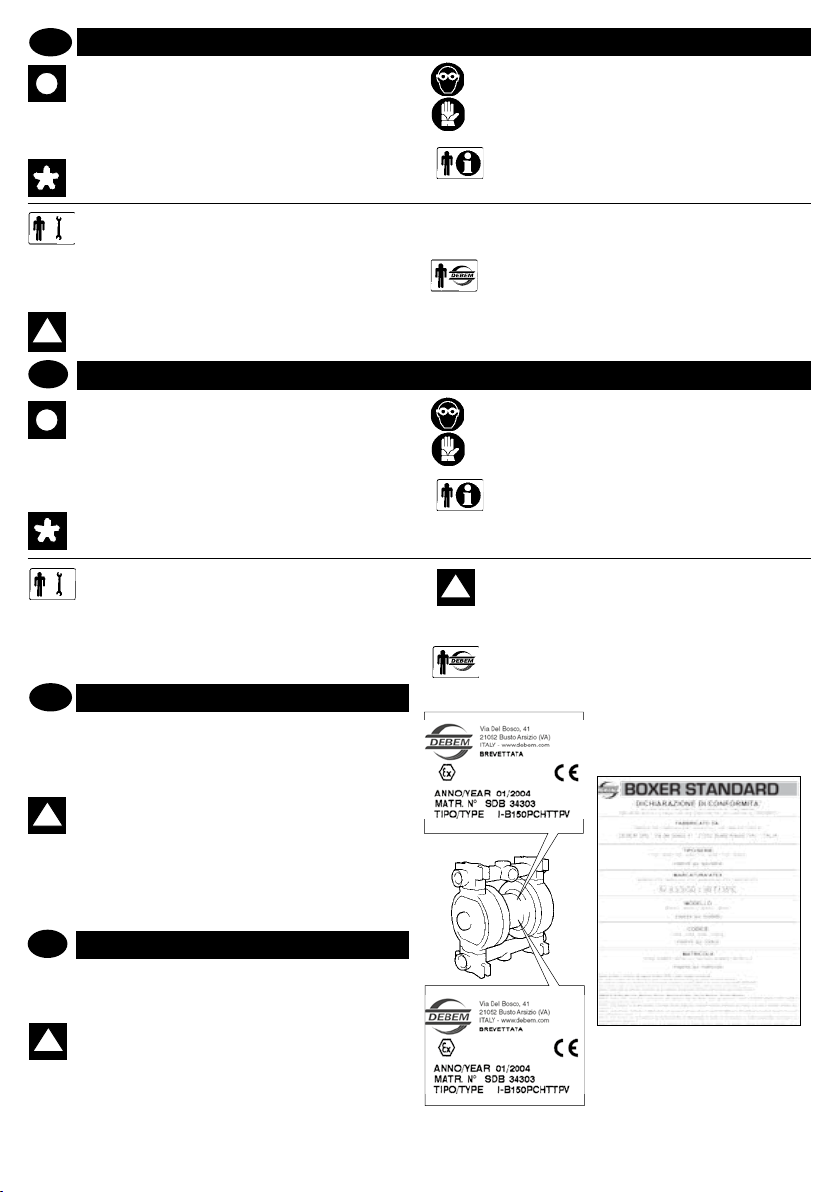
IDENTIFICAÇÃO DA BOMBA
P
Cada bomba tem uma matrícula de identicação que traz as
especicações e os materiais de composição. Em caso de
comunicação com o fabricante, o revendedor ou os centros de
assistência autorizados, precisar os dados indicados.
ATENÇÃO: proibido retirar e/ou modicar a matrícula de identicação da bomba e/ou os dados
!
nela registrados.
O código de identicação * que aparece em correspondência
de “TIPO” da matrícula, especica a composição e os mate-
riais de fabricação da bomba, com o objetivo de determinar a
idoneidade com o produto que será bombeado.
GB
PUMP IDENTIFICATION
Each pump has an identication plate carrying its specication
details and materials. Always refer to this data when contacting
the manufacturer, dealer or customer service centers.
WARNING: removing or altering this identication
!
plate and or the data it contains is forbidden.
Identication code * on the plate against the “TYPE” heading
species the composition and the materials used to build the
pump. This data will help ascertain whether the pump is suitable
for the product to be pumped.
-
5
WARNING The personnel in charge of installing,
testing and servicing the pump must have a
!
suitable technical knowledge of potentially
explosive atmospheres and of the relevant risks.
EXTRAORDINARY PROCEDURES: Identies operations that
can only be performed by the after-sales service technicians at
the Manufacturer’s premises.
CONDUCT
II 2/2 GD c IIB T135°C
II 3/3 GD c IIB T135°C
STANDARD
info@debem.it
Page 6

MARCAÇÃO E INFORMAÇÕES GERAIS
P
As bombas, de acordo com a Diretiva 94/9/CEE, trazem a
seguinte marcação de identicação:
II 2/2 GD c IIB T135°C
: símbolo de segurança, de acordo com a DIN 40012
apêndice A.
II 2/2 GD: aparelho de superfície para uso em áreas com
presença de gás, vapores ou neblinas, bem como nuvens
de poeiras combustíveis no ar, que ocasionalmente ocorram
durante o funcionamento normal (EN 1127-1, par. 6.3), tanto
na área externa quanto na interna (ÁREA 1).
As bombas, de acordo com a Diretiva 94/9/CEE, trazem a seguinte
marcação de identicação:
II 3/3 GD c IIB T135°C
: símbolo de segurança, de acordo com a DIN 40012,
apêndice A.
II 3/3GD: aparelho de superfície para uso em áreas em que resulte
improvável, ou rara e por curtos períodos a presença de gases,
vapores ou neblinas, bem como nuvens de poeiras combustíveis
no ar, durante o funcionamento tanto em área
externa como interna (ZONA 2).
MARKINGS AND GENERAL INFORMATION
GB
In compliance with the 94/9/CEE standards, the pumps carry
the following identication marks:
II 2/2 GD c IIB T135°C
: safety symbol to Din 40012 attachment A.
II 2/2GD: surface equipment for use in areas with the presence
of gases, vapors or mists in addition to clouds of combustible
dust in the air that occur occasionally during normal operation (EN 1127-1 par. 6.3), both in external and internal areas
(ZONE 1).
c: aparelho em modalidade de proteção de tipo construtivo
(EN 13463-5).
IIB: com exclusão dos seguintes produtos: hidrogênio, aceti-
leno, sulfureto de carbono.
T135°C:classe de temperatura admitida. O utilizador deve pro-
cessar uidos em temperatura conforme com tal classicação,
levando em conta as indicações deste manual e as disposições
legais em vigor. O utilizador, além disso, deve levar em conta
as temperaturas de ignição dos gases, vapores e neblinas,
bem como nuvens de poeiras combustíveis presentes na
área de utilização.
A documentação técnica está depositada junto ao TÜV
NORD CERT da cidade de Hannover, Alemanha.
c: aparelho em modalidade de proteção de tipo construtivo (EN
13463-5).
IIB: com exclusão dos seguintes produtos: hidrogênio, acetileno,
sulfureto de carbono.
T135°C: classe de temperatura admitida. O utilizador deve pro-
cessar uidos em temperatura conforme com tal classicação,
levando em conta as indicações deste manual e as disposições
legais em vigor. O utilizador, além disso, deve levar em conta as
temperaturas de ignição dos gases, vapores e neblinas, bem como
nuvens de poeiras combustíveis presentes na área de utilização.
A documentação técnica está depositada junto ao TÜV NORD
CERT da cidade de Hannover, Alemanha.
c: protection by constructional safety (EN 13463-5).
IIB: Excluding the following products hydrogen, acetylene,
carbon disulphide.
T135°C: Class of admitted temperatures. The processed uid
temperature value must fall within such class range and the
user must comply with the instructions contained in the manual
and with the current laws. Furthermore, the user must take
into account the ignition point of the gases, vapors and mists
in addition to clouds of combustible powder in the air existing
in the area of use.
The technical sheet is deposited with TÜV NORD CERT
Hanover.
In compliance with the 94/9/CEE standards, the pumps carry
the following identication marks:
II 3/3 GD c IIB T135°C
: safety symbol to Din 40012 attachment A.
II 3/3GD: surface equipment used in areas where the presence
of gas, vapors or mists in addition to clouds of combustible
powder in the air is unlikely during normal operation both in
external and internal areas and, if it does occur, it will only
persist for a short period (ZONE 2).
www.debem.it
c: protection by constructional safety (EN 13463-5).
IIB: Excluding the following products: hydrogen, acetylene,
carbon disulphide.
T135°C: Class of admitted temperatures. The processed uid
temperature value must fall within such class range and the
user must comply with the instructions contained in the manual
and with the current laws. Furthermore, the user must take
into account the ignition point of the gases, vapors and mists
in addition to clouds of combustible powder in the air existing
in the area of use.
The technical sheet is deposited with TÜV NORD CERT
Hanover.
6
Page 7
VERSÃO
CONDUCT
C
COLETOR
DUPLICADO
X
VERSION
CONDUCT
C
SPLIT
MANIFOLD
X C
X
X C
O-RINGS
T - PTFE
D - EPDM
ESFERAS
ALOJAMENTOS
P - polipropilno
F - PVDF
A - AISI 316
ESFERAS
T = PTFE
A = AISI 316
MEMBRANA
LADO FLUIDO
T = PTFE
LADO DI AR
MEMBRANAS
H - Hytrel
M - Santoprene
V - Viton
N - NBR
L - Alluminio
I - PE-UHMW
D = EPDM
N = NBR
D - EPDM
N - NBR
R - PPS-V
(apenas por BOXER
100 e BOXER 150)
A - AISI 316
A = AISI 316
T = PTFE
T = PTFE T = PTFE
H - Hytrel
6 Texto BOXER502 apenas corpo em ALU - AISI 316
7 Texto BOXER522 apenas corpo em PP - PP+CF - PVDF
* BOXER100/BOXER150 montam apenas sedes de esfera em PPS-V, que não em alumínio
** BOXER522/BOXER503 em plástico não podem montar o-ring em PTFE, apenas VITON ou EPDM
O-RINGS
T - PTFE
D - EPDM
Polypropylene
BALL SEATS
F - PVDF
P -
BALLS
T = PTFE
A = AISI 316
FLUID SIDE
DAPHRAGMS
T = PTFE
AIR SIDE
DAPHRAGMS
H - Hytrel
M - Santoprene
V - Viton
N - NBR
A - AISI 316
L - Alluminio
D = EPDM
D - EPDM
N - NBR
(only
I - PE-UHMW
R - PPS-V
BOXER 100 and
N = NBR
BOXER 150)
A - AISI 316
A = AISI 316
T = PTFE
T = PTFE T = PTFE
H - Hytrel
6 BOXER502 inscription only on body in ALU - AISI 316
7 BOXER522 inscription only on body in PP - PP+CF - PVDF
* BOXER100/BOXER150 only mounts ball seats in PPS-V, not in aluminium
** BOXER522/BOXER503 in plastic cannot mount O-rings in PTFE, only in VITON or EPDM
P- D T A P D X C
P - PP
PC - PP + CF
FC - PVDF + CF
AL - ALU
B100 = Boxer 100
B150 = Boxer 150
A - AISI 316
6
7
B251 = Boxer 251
B502 = Boxer 502
B522 = Boxer 522
A - AISI 316
Foodboxer 30
B503 = Boxer 503
FB30 =
FB50 = Foodboxer 50
FB80 = Foodboxer 80
FB100 = Foodboxer 100
FB251 = Foodboxer 251
FB502 = Foodboxer 502
1 MICROBOXER monta apenas membranas internas em HYTREL / SANTOPRENE
CORPO BOMBA
CÓDIGO DE IDENTIFICAÇÃO
B81-
P
B15 = Boxer 15
MICR = MIcroboxer1MIN = Miniboxer2B50 = Boxer 503B80 = Boxer 804B81 = Boxer 81
2 Texto MINIBOXER apenas corpo em AISI 316
3 Texto BOXER50 apenas corpo em PP - PP+CF - PVDF - ALU
4 Texto BOXER80 apenas corpo em AISI 316
7
P- D T A P D X C
PUMP CASING
P - PP
PC - PP + CF
IDENTIFICATION CODE
B81-
GB
B15 = Boxer 15
MICR = MIcroboxer1MIN = Miniboxer2B50 = Boxer 503B80 = Boxer 804B81 = Boxer 81
FC - PVDF + CF
AL - ALU
A - AISI 316
6
B100 = Boxer 100
B150 = Boxer 150
B251 = Boxer 251
B502 = Boxer 502
7
B522 = Boxer 522
B503 = Boxer 503
A - AISI 316
Foodboxer 30
FB30 =
FB50 = Foodboxer 50
FB80 = Foodboxer 80
FB100 = Foodboxer 100
FB251 = Foodboxer 251
FB502 = Foodboxer 502
info@debem.it
1 MICROBOXER only mounts internal membranes in HYTREL / SANTOPRENE
2 MINIBOXER inscription only on body in AISI 316
3 BOXER50 inscription only on body in PP - PP+CF - PVDF - ALU
4 BOXER80 inscription only on body in AISI 316
Page 8

DESCRIÇÃO DA BOMBA
P
Uso planejado
As bombas pneumáticas BOXER foram projetadas e construídas para o bombeamento de líquidos com viscosidade aparente de 1 a 50,000 cps em 20 °C, de materiais compatíveis
quimicamente com os componentes de fabricação da bomba.
O funcionamento da bomba é permitido com temperaturas de
exercício do uido entre +3 °C e 65/95 °C, em função dos materiais dos componentes. A utilização é em função do tipo de
material de composição da bomba, da classe de temperatura
e do tipo de uido. Todavia, a máxima temperatura admitida
para uidos ou poeiras de processamento está subordinada
e/ou diminuída em função do material da bomba; em caso de
ultrapassagem do valor de referência, não está garantido o
respeito da temperatura máxima denida na marcação.
A seguir é indicada a fórmula para determinar a temperatura
máxima permitida de processo do uido para os amortecedores
na versão CONDUCT ( II 2/2 GD c IIB T135°C).
SOMENTE PARA BOMBAS A SEREM INSTALADAS EM ZONA 1.
CLASSE DE
TEMPERATURA
ATEX
T4 Tx Tf
135°C 55°C
GB
PUMP DESCRIPTION
Proposed use
The air-driven BOXER pumps have been designed and constructed to pump liquids with an apparent viscosity of between
1 and 50.000 cps at 20°C that are chemically compatible with
the pump’s components. Fluid service temperatures must range
from +3°C to a maximum of 65/95°C according to the material
of the components. Its use is dened by the type of material
used to build the pump, the temperature class and the type of
uid. The maximum temperature allowed for process uid or
powder depends on and/or is declassed by the material of the
pump; if exceeded, respect of the maximum temperature shown
on the marking cannot be guaranteed.
FATOR DE
CÁLCULO
(somente para
ZONA 1)
- =
- =
MÁXIMA
TEMPERATURA
DE PROCESSO
DO FLUIDO
95°C
CLASSE DE TEMPERATURA PARA BOMBAS A SEREM
INSTALADAS EM AMBIENTE EXPLOSIVO (ZONA 1): A
classe de temperatura de referência para a proteção contra
o risco de explosão das bombas destinadas ao uso em zona
1, com presença de atmosferas explosivas, é T 135 °C (T4); a
seguir, indicamos dados e condições operacionais:
DEFINIÇÃO DOS DADOS DE CÁLCULO:
T4 = classe de temperatura ATEX 135°C
Ta = temperatura ambiente máxima 40°C;
Tl = temperatura máxima da bomba utilizada a seco no am-
biente de trabalho (50°C);
Δs = fator de segurança (5°C);
Tx = fator de cálculo (Tl + Δs) somente para ZONA 1;
Tf = temperatura máxima admitida de processo do uido
ATENÇÃO: em consideração do campo de varia-
!
ção admitido da temperatura ambiente em zona 1,
temperaturas de processo do uido superiores às
indicadas acima, além de provocar danos ao amortecedor,
não permitem respeitar as correspondentes classes de
temperatura T4 (135°C). Nos casos em que o utilizador
prever que tais limites de temperatura, conforme previsto
neste manual, sejam excedidos, será necessário instalar no
sistema um dispositivo de proteção que impeça o alcance
da temperatura máxima admitida de processo do uido.
A temperatura máxima do aparelho foi determinada sem
depósito de poeira nas superfícies externas e internas.
TEMPERATURE CLASSES FOR PUMPS TO BE INSTALLED
IN AN EXPLOSIVE ENVIRONMENT (ZONE 1): T135°C (T4) is
the temperature class corresponding to the protection against
the risk of explosion of the pumps designed for use in explosive
atmo-spheres; the data and operating conditions are shown
here below:
DEFINITION OF THE CALCULATION DATA:
T4 = ATEX temperature class 135°C
Ta = maximum ambient temperature 40°C;
Tl = maximum temperature for dry use of the pump in the
workplace (50°C);
Δs = safety factor (5°C);
Tx = calculation factor (Tl + Δs) only for ZONE 1;
Tf = maximum allowed uid processing temperature
The formula used to determine the maximum allowed uid
processing temperature for CONDUCT version pumps ( II
2/2 GD c IIB T135°C) is shown here below.
ONLY FOR PUMPS TO BE INSTALLED IN ZONE 1.
ATEX
TEMPERATURE
CLASS
T4 Tx Tf
135°C 55°C
CALCULATION
FACTOR
(only for ZONE 1)
- =
- =
MAXIMUM
FLUID
PROCESSING
TEMPERATURE
95°C
www.debem.it
WARNING: In consideration of the admitted ambient
temperature variation range in zone 1, uid service
!
temperature values higher than those indicated
above will not permit compliance to the corresponding T4
(135°C) temperature classes besides causing damages to
the pump. Where the user presumes that the temperature
limits set forth in this manual may be exceeded, a protective
device must be installed on the system to prevent the
maximum allowed uid processing temperature from being
reached.The equipment’s maximum temperature has been
determined with no powder deposits on the external and
internal surfaces.
8
Page 9

P
Princípio de funcionamento
O ar que entra por trás da membrana empurra o produto em
direção à saída. Contemporaneamente, mediante o eixo, arrasta a membrana oposta, que produz uma sucção na aspiração.
No nal do curso, o ciclo inverte-se.
Usos impróprios:
ATENÇÃO: qualquer outra utilização da bomba
BOXER distinta de quanto anteriormente descrito
e precisado no capítulo “CARACTERÍSTICAS TÉCNICAS” será considerada imprópria e portanto proibida
pela empresa Debem.
Especialmente, É PROIBIDO o uso da bomba Boxer para:
- criação de vácuo;
- uso como válvula de interceptação, como válvula de retenção
ou como válvula de dosagem;
- o uso com líquidos a serem bombeados não compatíveis,
quimicamente, com o material de fabricação;
- o uso com produtos em suspensão que tenham peso espe-
cíco superior ao do líquido (por exemplo, água com areia);
- com pressões pneumáticas, temperaturas e características
do produto em desacordo com os dados técnicos da bomba;
ATENÇÃO: para uidos alimentares que não neces-
!
sitam de certicação especíca, aconselhamos o
uso de bombas da série FOODBOXER, de acordo
com as normas FDA.
ATENÇÃO: face à inúmera variedade de produtos e
composições químicas, o utilizador é considerado
!
o maior conhecedor das reações e compatibilidade
com os materiais de fabricação da bomba. Portanto, antes
do uso, realizar com cuidado todos os controles e testes
necessários para evitar situações perigosas, mesmo se
improváveis, que não podem ser notas e imputáveis ao
fabricante.
ATENÇÃO: o utilizador deve avaliar a relação entre
!
a máxima temperatura de superfície da bomba
indicada na marcação e a temperatura mínima de
ignição das camadas de poeira e das nuvens de poeira,
assim como indicado na EN 1227-1.
GB
Functioning principles
The air introduced behind the diaphragm pushes the product
to the delivery side. At the same time, it uses the shaft to draw
the opposite diaphragm, which causes suction at the intake
side. When complete, the cycle reverses.
Improper use:
WARNING: use of a Boxer pump for any other use
other than that previously described in the chapter
!
entitled “TECHNICAL CHARACTERISTICS” is to
be considered improper use of the pump and is therefore
forbidden by Debem.
In particular, it is FORBIDDEN to use Boxer pumps for :
WARNING: since an endless variety of products and
chemical compositions exist, the user is presumed
! !
to have the best knowledge of their reaction and
compatibility with the pump’s construction materials.
Therefore, before using the pump, all necessary checks
and tests must be performed with great care to avoid even
the slightest risk, an event that the manufacturer cannot
foresee and for which he cannot be held responsible.
WARNING: the user must consider the ratio be-
!
tween the pump’s maximum surface temperature
indicated on the marking and the minimum ignition
temperature of the layers and clouds of powder as shown
in the EN1227-1.
ATENÇÃO: qualquer uso da bomba alheio às
instruções indicadas no manual de uso e manu-
!
tenção, implicará a decadência dos requisitos de
segurança e tutela contra o perigo de explosão. Foram
analisados os riscos ligados à utilização da bomba nas
precisas condições prescritas pelo manual de uso e
manutenção: a análise dos riscos ligados à interface com
outros componentes do sistema é por conta do instalador.
Normativa ATEX: Cabe ao utilizador do aparelho
a responsabilidade de classicação da própria
!
zona; por outro lado, cabe ao fabricante a iden-
ticação da categoria do aparelho.
- production of vacuum;
- operation as an on-off valve, as a non-return valve or as a
metering valve
- operation with liquid that is chemically incompatible, with the
materials of construction;
- operation with suspended products whose specic weight
is higher than the liquid’s (for example with water and sand);
- with air pressures, temperatures or product characteristics
that do not comply with the pump’s technical data;
- edible liquids.
WARNING: for the alimentary uids for which a
!
special certication is not required, we recommend to make use of pumps belonging to the
FOODBOXER series, according to FDA rules.
WARNING. Use of the pump that does not comply
with the instructions indicated in the use and
explosion protection requirements. The risks associated
with use of the pumps under the exact conditions set forth
in the use and maintenance manual have been analysed,
whilst the analysis of the risks associated with the interface with other system components must be carried out
by the installer.
maintenance manual will cancel the safety and
ATEX: The user is responsible for classifying the
!
area of use whilst identication of the equipment
category is the responsibility of the manufacturer.
9
info@debem.it
Page 10
CARACTERÍSTICAS TÉCNICAS
P
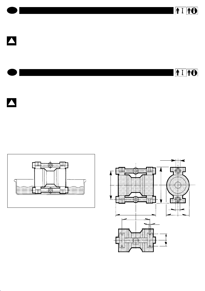
Os dados referidos ao desempenho referem-se às execuções padrão. Os valores de “Caudal MAX” e “Capacidade de aspiração”
referem-se ao bombeamento de água a 18 °C; com o coletor sub-
merso (ver gura 1). (1) (2)
ATENÇÃO: a capacidade de aspiração negativa a
!
seco declarada refere-se à captação de uidos com
viscosidade e peso especíco igual a 1; o desempe-
nho e a vida útil das membranas da bomba estão subordinados aos seguintes fatores:
- viscosidade e peso especíco do uido;
- comprimento e diâmetro do tubo de aspiração.
TECHNICAL FEATURES
GB
The performances data refers to standard versions. “MAX
delivery” and “Suction capacity” values refer to the pumping of
water at 18°C with a submersed manifold (please see g. 1).
WARNING: the declared capacity of dry negative
suction refers to the intake of uids with a viscos-
!
ity and specic weight equal to 1; the performance
and duration of the pump’s membrane depend on the
following factors:
- the uid’s viscosity and specic weight;
- the length and diameter of the suction pipe.
(1) (2)
ASPIRAÇÃO NEGATIVA: com uidos máximo até 5000 cps, a
18 °C
ASPIRAÇÃO EM NÍVEL INFERIOR AO DO LÍQUIDO A SER
ASPIRADO com uidos até 50.000 cps, a 18 °C
NEGATIVE SUCTION: with uids max. up to 5,000 cps at 18° C
BELOW HEAD SUCTION: with uids up to 50,000 cps at 18° C
B15 - MICROBOXER - MINIBOXER
B50 - B80 - B81 - B100 - B150
B251 - B502 - B522 - B503
m
www.debem.it
g. 1
10
D
B
C
a
A
E
F
G
Page 11

Bomba/pump
BOXER B15
MICROBOXER plástica/Plastic
MICROBOXER Alu 1/2” 120 165 168 138 120 8 70
MICROBOXER Inox/FOODBOXER 30 1/2” 120 165 168 138 120 8 70
MINIBOXER plástica/
MINIBOXER Inox/FOODBOXER 50 1/2” 150 210 230 195 165 9 75
BOXER B50 Alu 1/2” 152 240 234 198 168 6,5 85
BOXER B80 Inox/FOODBOXER 80 1” 170 305 271 217 214 8 93
BOXER B81 plástica/
BOXER B81 Alu 1” 170 303 277 222 213 8 100
BOXER B100 plástica/ Plastic
BOXER B100 Alu/Inox 1” 201 314 323 269 213 8 110
BOXER B100 Inox/FOODBOXER 100 1” 201 307 326 272 213 8 110
BOXER B150 plástica/ Plastic 1 1/4”
BOXER B150 Alu
BOXER B150 Inox/FOODBOXER 150
BOXER B251 plástica/ Plastic 1 1/2”
BOXER B251 Alu
BOXER B251 Inox/FOODBOXER 251
BOXER B502 plástica/ Plastic
BOXER 522 Plástica/Plastic
BOXER B502 Inox/FOODBOXER 502 2” 348 470 704 582 364 11 250
BOXER B502 Alu
BOXER B503 plástica/ Plastic
BOXER 503 Alu
BOXER 503 Inox/FOODBOXER 503
plástica/Plastic
Plastic
Plastic
m-a A
3/8” 80 147 181 115 103 5 64
1/2” 120 165 168 138 120 8 70
1/2” 150 240 234 200 168 8 80
1” 170 308 274 219 213 6,5 92
1” 201 329 325 263 228 8 110
1 1/4”
1 1/4”
1 1/2”
1 1/2”
2” 350 580 726 580 400 14 200
2” 404 580 726 606 580 250
2” 350 566 621 521 364
3” 350 580 726 580 400 14 200
3” 350 580 806 694 360 15 272
3” 350 546 838 682 361 11 250
Ø
220 400 387 302 267 8 122
225 405 385 305 265 8 125
225 405 385 305 265 8 125
254 484 491 415 326 8 138
252 484 491 415 327 8 138
252 484 491 415 327 8 138
B C D E F
Ø
12,5
G
182,5
11
info@debem.it
Page 12

B522 B503
B502
FB502
B251
FB251
B150
FB150
FB100
B81 B100
FB 80
B50 B80
FB50
MINIBOXER
FB30
56
67
38
n.a.
546549
162021
121416
7,5
8,5
5
6,5
---
3,6
4,2
---
1,923,8
-
-
8,2
6,5
4
-
-
54
32
21
11
-
10,5
-
6,5
B522 B503
B502
FB502
B251
FB251
B150
FB150
FB100
B81 B100
FB 80
B50 B80
FB50
MINIBOXER
FB30
56
67
38
n.a.
546549
162021
121416
7,5
8,5
5
6,5
---
3,6
4,2
---
1,923,8
-
-
8,2
6,5
4
-
-
54
32
21
11
-
10,5
-
6,5
B15 MICROBOXER
de
unid.
med.
pol. 3/8” 1/4” 3/8” 3,8” 3,8” 3,8” 3,8” 1/2” 1/2” 1/2” 1/2” 3/4”
mt. 3 5 5 5 5 6 5 5 6 5 4 5
DADOS TÉCNICOS
P
Engates aspiração/saída pol. 3/8” 1/2” 1/2” 1/2” 1” 1” 1” 1 1/4” 1 1/2” 2” 2” 3”
Conexão de ar
Capacidade de aspiração a seco(1)
(membrana PTFE)
www.debem.it
95 95 95 95 95 95 95 95 95 95 95 95
65 65 65 65 65 65 65 65 65 65 65 65
65 65 65 65 65 65 65 65 65 65 65 65
C°
PP + CF (zona 1)
Alu. - Aisi 304/316 - PVDF+ CF
(zona 1)
PP (zona 2)
Temperatura
máxima
Pressão ar (MIN-MÁX) bar 2-8 2-8 2-8 2-8 2-8 2-8 2-8 2-8 2-8 2-8 2-8 2-8
uido
95 95 95 95 95 95 95 95 95 95 95 95
17 30 50 50 90 100 150 220 340 650 650 850
1,1 1,6
C°
Lit/
min.
Kg
- PVDF
água a 18° C com coletor
(2)
Alu. - Aisi 304/316 - PVDF
(zona 2)
Caudal máximo
aspirador submergido
Peso líquido - PP
- ALU.
- INOX
70 80 80 82 82 82 82 82 82 82 82 82
Ruído (a 5 bar com esferas de borracha) dB
(A)
12
B15 MICROBOXER
unit
TECHNICAL DATA
GB
Intake/delivery ttings inches 3/8” 1/2” 1/2” 1/2” 1” 1” 1” 1 1/4” 1 1/2” 2” 2” 3”
65 65 65 65 65 65 65 65 65 65 65 65
95 95 95 95 95 95 95 95 95 95 95 95
m 3 5 5 5 5 6 5 5 6 5 4 5
inches 3/8” 1/4” 3/8” 3,8” 3,8” 3,8” 3,8” 1/2” 1/2” 1/2” 1/2” 3/4”
(diaphragm
(1)
Air tting
Suction capacity whilst dry
PTFE)
Air pressure (MIN-MAX) bars 2-8 2-8 2-8 2-8 2-8 2-8 2-8 2-8 2-8 2-8 2-8 2-8
C°
PP + CF (zone 1)
Alu. - Aisi 304/316 - PVDF + CF
(zone 1)
Fluid max
65 65 65 65 65 65 65 65 65 65 65 65
95 95 95 95 95 95 95 95 95 95 95 95
C°
L/min. 17 30 50 90 90 100 150 220 340 650 650 850
water at 18° C with submersed
PP (zone 2)
Alu. - Aisi 304/316 - PVDF
(zone 2)
(2)
temp.
pressure
Max capacity
1,1 1,6
Kg
- PVDF
- ALU.
- INOX
intake manifold
Net weight - PP
Noise (at 5bar with rubber balls) dB (A) 70 80 80 82 82 82 82 82 82 82 82 82
Page 13

MODALIDADES DA GARANTIA
P
A bomba BOXER é um produto de qualidade que nos é reconhecida, com plena satisfação, por todos os compradores.
Em caso de eventuais anomalias, deverá ser contatado o
SERVIÇO DE ASSISTÊNCIA DO FABRICANTE, o revende-
dor ou o centro de assistência mais próximo, que rapidamente
prestará o auxílio necessário. Em todas as circunstâncias, indicar os dados a seguir:
A – o endereço completo
B – a identicação da bomba
C – a classe de proteção contra o risco de explosão
D- a descrição da anomalia
Todas as bombas BOXER estão cobertas pela seguinte fór-
5. As partes com defeito deverão ser reenviadas ao Fabricante, que se reserva o direito de realizar um controle das
mesmas junto à sua ocina
para detectar o real defeito ou, ao contrário, identicar as
razões externas que podem ter determinado o dano. Caso
as partes não resultem defeituosas, o Fabricante reserva-se
o direito de debitar o custo integral das peças anteriormente
substituídas em garantia.
O Fabricante não arcará com as despesas e os riscos do
transporte das partes defeituosas e das partes consertadas
ou das fornecidas em substituição, com inclusão dos eventuais impostos alfandegários.
O conserto ou a substituição das partes com defeito constitui
plena satisfação das obrigações de garantia.
A garantia NÃO cobrirá algum dano indireto e, especialmente,
GB
WARRANTY
The high quality of BOXER pumps is often conrmed to us by
the end users.
However, should any defect appear, please contact the
Manufacturer’s After-Sales Service, your dealer or the nearest
Customer Service Centre twhere you will receive assistance as
quickly as possible. In any case, please provide:
A. Your complete address
B. Pump identication
C. Explosion risk protection class
D. Anomaly description
mula de seguro:
1. A bomba tem garantia de 12 meses para todas as partes
mecânicas nas quais forem evidenciados defeitos. O período
de garantia será calculado a partir da data de entrega.
2. Todo e qualquer defeito deverá ser noticado ao Fabricante, por escrito, no prazo de 8 dias.
3. A intervenção em garantia será realizada exclusivamente
junto às nossas ocinas, prévio envio da bomba defeituosa.
4. Em caso de conserto ou substituição de partes da bomba,
a garantia não será estendida.
a eventual falta de produção. Além disso, estão excluídos da
garantia todos os materiais de consumo e desgaste normal
(membranas, alojamentos de esferas e esferas etc.).
Não estão cobertas pela garantia as partes que resultarem
danicadas por causa de instalação errada, negligência ou
descuido no uso, manutenção errada, danos devidos ao
transporte e por qualquer circunstância que não se rera a
defeitos de funcionamento ou de fabricação.
A garantia está excluída em todos os casos de uso impróprio ou aplicações incorretas e da inobservância das
informações contidas neste manual.
Para dirimir eventuais controvérsias, o Foro competente
é o de Busto Arsízio, Itália.
All BOXER pumps are covered by the following warranty:
1. Twelve months for any faulty mechanical parts. The warranty
period starts from the date of supply.
2. Any fault or anomaly must be reported to the Manufacturer
within eight days.
3. Warranty repair will be carried out exclusively at the Manufacturer’s premises. Transportation charges will be at the client’s expense.
4. Warranty shall not be extended in case of repair or
replacement.
5. Faulty parts must be forwarded to the Manufacturer who
reserves the right to test them in this own factory to identify the
fault or any external reason that may have caused it. Should the
parts be found not faulty, the Manufacturer reserves the right
to invoice the total cost of the parts that had been replaced
under this warranty.
Costs and transportation risks of faulty, repaired or replaced
parts including custom charges will be borne entirely by the
client.
Repair or replacement of faulty parts cover any obligation
under this warranty.
The warranty DOES NOT cover any indirect damage and in
particular any normal consumable material such as diaphragms,
ball seats, and others.
The warranty does not cover parts damaged as a consequence
of incorrect installation, carelessness, neglect, incorrect
maintenance, or damages due to transportation or to any
other reason or event that is not directly linked to functional or
manufacturing defects.
The warranty excludes all cases of improper use of the
pump or incorrect applications or non-observance of the
information contained in this manual.
Any controversy falls within the jurisdiction of the Court
of Busto Arsizio.
13
info@debem.it
Page 14

PRESCRIÇÕES DE SEGURANÇA
P
PRESCRIZIONI DI SICUREZZA
Praticas perigosas, arriscadas ou em desacordo com as prescrições de segurança e com quanto tratado neste manual,
podem causar graves lesões, danos materiais ou até mesmo
explosão fatal, não imputáveis ao fabricante.
ATENÇÃO: as presentes instruções são indispen-
!
sáveis para que a bomba corresponda plenamen-
te aos requisitos da diretiva 94/9/CE e portanto
devem estar sempre disponíveis, devem ser conhecidas,
compreendidas e aplicadas.
ATENÇÃO: o pessoal encarregado pela instala-
!
ção, a inspeção e manutenção da bomba deve ter
recebido adequado preparo técnico, além de pos-
suir conhecimentos adequados em matéria de atmosfera
potencialmente explosiva e riscos a esta relativos.
ATENÇÃO: qualquer uso da bomba alheio às
!
instruções indicadas no manual de uso e manutenção, implicará a decadência dos requisitos de
segurança e tutela contra o perigo de explosão.
ATENÇÃO: a temperatura máxima admitida para
!
uidos ou poeiras de processo (em zona 1) é igual
a 65/95º C em função dos materiais de fabricação;
em caso de ultrapassagem, não é garantido o respeito da
máxima temperatura indicada na marcação.
ATENÇÃO: antes de intervir na bomba e/ou antes
!
de realizar manutenções ou consertos, é necessário:
A – descarregar o produto que está sendo bombeado;
B – providenciar a lavagem interna com uido idôneo
(não inamável);
C – secionar a alimentação do ar mediante a válvula correspondente e certicar-se de que não haja pressões residuais na bomba;
D – fechar as válvulas manuais de interceptação produto
(aspiração e saída);
E- desconectar a alimentação do ar da rede;
F - Usar os equipamentos de proteção individual idôneos
para a operação (máscaras para o rosto, luvas, botas de
segurança, aventais etc.):
SAFETY RULES
GB
SAFETY RULES
Dangerous or hazardous practices or practice not complying
with the safety rules and with the recommendations contained
herein, may cause serious injuries, material damage and even
explosions and /or death for which the manufacturer cannot be
held responsible.
WARNING: these instructions are essential for
!
the pumps’ compliance to the requirements of the
94/9/CE directive and must therefore be available,
known, understood and applied.
WARNING: the personnel in charge of installing,
inspecting and servicing the pumps must have
!
suitable
WARNING: before intervening on the pump and/or
!
servicing or repairing it, please note that you must:
A. Discharge any product that was being pumped
B. Wash it internally using a suitable non-ammable uid,
then drain.
C. Cut-off the air supply using the relevant valve and make
sure that no residual pressure remains inside it.
D. Close all on-off valves (delivery and intake sides)
relative to the product;
E. Disconnect the network air supply;
F. Wear suitable individual protection before any maintenance or repair (goggles/face protection, gloves, closed
shoes, aprons and others).
ATENÇÃO: antes de utilizar a bomba, certicar-se
de que o uido a ser bombeado seja compatível
!
com a classe de proteção contra o risco de explosão e com os materiais de fabricação: perigo de corrosões, vazamentos do produto e/ou explosões devidas a
reações químicas.
Para a instalação e o uso em ambiente potencialmente explosivo, respeitar as seguintes precauções gerais:
- controlar que a bomba esteja cheia e o nível esteja, possivelmente, acima desta de 0,5 m;
- controlar que no uido tratado não haja ou possa haver partes sólidas com dimensões signicativas o formato prejudicial;
technical knowledge and training in matters concerning
potentially explosive atmospheres and the related risks.
WARNING: use of the pumps in a manner that does
not comply with the instructions indicated in the
!
use and maintenance manual will cancel all the requirements for safety and protection against of explosions.
WARNING: the maximum allowed temperature
for process uids or powder (zone 1) is equal to
!
65/95°C depending on the construction materials;
if exceeded, respect of the maximum temperature marked
on the machine cannot be guaranteed.
WARNING: before using the pump, make sure that
!
the uid to be pumped is compatible with the explo-
sion protection class and with construction materials of the pump: DANGER OF CORROSION,PRODUCT
SPILLS AND/OR EXPLOSIONS CAUSED BY CHEMICAL
REACTIONS.
For installation and use in a potentially explosive
environment, comply with these general precautions:
- ascertain that the pump is full and if possible, that the level
is above it by 0.5 m;
- ascertain that the uid treated does not contain or cannot
contain large solids or solids of a dangerous shape;
www.debem.it
14
Page 15
P
- que não haja estrangulamentos na entrada ou na saída da
bomba, para evitar fenômenos respectivamente de cavitação
e esforço do motor pneumático;
- controlar que as tubulações de conexão sejam sucientemente resistentes e que não possam sofrer deformações sob
o peso da bomba e da aspiração; da mesma forma, vericar
que a bomba tampouco sofra o peso das tubulações;
- se a bomba tiver que permanecer inativa por longos perío-
dos, limpá-la cuidadosamente, fazendo circular um uido
detergente não inamável compatível com os materiais de
fabricação da bomba;
- se a bomba permaneceu desligada por longos períodos, é
oportuno deixar circular água limpa por alguns minutos, para
evitar o risco de incrustações;
- antes da colocação em funcionamento, após longos períodos de parada, limpar as superfícies internas e externas com
um pano úmido.
- controlar a ação de terra;
- proteger sempre a bomba contra possíveis choques, provocados acidentalmente por veículos em movimento ou ma-
teriais diversos contundentes, que poderiam danicá-la e/ou
reagir ao contato;
- proteger o ambiente circunvizinho dos respingos resultantes
de avarias acidentais da bomba;
- em caso de ruptura total das membranas, o uido pode entrar no circuito pneumático, danicá-lo e sair pela descarga.
Portanto, é necessário dirigir a descarga do ar, mediante tubulação, para uma área segura.
ATENÇÃO: a alimentação do ar nunca deve resultar superior a 7bars ou inferior a 2bars.
!
ATENÇÃO: em caso de uso para o bombeamento
!
de uidos agressivos, tóxicos ou perigosos para
a saúde, é necessário instalar na bomba uma adequada proteção para a contenção e a coleta e sinalização
do produto em caso de vazamento: perigo de poluição,
contaminação, lesões e/ou morte.
ATENÇÃO: está proibido o uso da bomba com
uidos não compatíveis com os materiais dos
!
componentes ou em ambiente com presença de
uidos não compatíveis.
GB
- ensure thet the intake or delivery ports are not obstructed nor
limited to avoid cavitation or pneumatic motor strain;
- also ascertain that the connection piping is strong enough and
cannot be deformed by the pump weight or by the intake. Also
check that the pump is not burdened by the weight of the piping.
- If the pump is to stay in disuse for a long period of time, clean
it carefully by running a non-ammable liquid detergent through
it that is compatible with the pump’s construction materials;
- if the pump was turned off for a long period of time, circulate
clean water it in for some minutes to avoid incrustations.
- before starting, after long periods of disuse, clean the internal
and external surfaces with a damp cloth;
- check the grounding;
ATENÇÃO: está proibida a instalação da bomba
!
em ausência de válvulas para a interceptação do
produto sobre a aspiração e sobre a saída, para
efetuar o corte, em caso de vazamento: perigo de vazamento descontrolado do produto.
ATENÇÃO: está proibida a instalação da bomba
!
sem a válvula de interceptação, válvulas de 3 vias
e válvula de não retorno no duto de alimentação
do ar para impedir que o uido bombeado entre no circuito pneumático em caso de ruptura das membranas:
perigo de entrada do uido no circuito do ar comprimido
e descarga no ambiente.
- always protect the pump against possible collisions caused by
moving objects or by various blunt materials that may damage
it or react with its materials;
- protect the pump’s surrounding ambient from splashes caused
by accidental pump failure;
- if the diaphragms are completely torn, the uid may enter the
air circuit, damaging it, and be discharged from the exhaust port.
It is therefore necessary for the exhaust port to be conveyed
by pipes to a safe area.
WARNING: the air supply pressure must never be
!
over 7 bar or below 2 bar.
WARNING: when using the pump with aggressive
or toxic liquids or with liquids that may represent a
!
health hazard you must install suitable protection
on the pump to contain, collect and signal any spills:
DANGER OF POLLUTION, CONTAMINATION, INJURIES
AND/OR DEATH.
WARNING: the pump must not be used with uids
that are not compatible with its construction
!
materials or in a place containing incompatible
uids.
WARNING: installing the pumps without on-off
!
valves on the intake and delivery sides to intercept
the product in case of spillage is forbidden: danger
of uncontrolled product spillage.
WARNING: installing the pumps without on-off,
three-way or check valves on the air supply
!
piping to prevent the pumped liquid from entering
the pneumatic circuit if the diaphragms are broken is
forbidden: danger of uid entering the compressed air
circuit and being discharged into the environment.
15
info@debem.it
Page 16

P
ATENÇÃO: Nos casos em que o utilizador prever
!
que os limites de temperatura, conforme previsto
neste manual, sejam excedidos, será necessário
instalar no sistema um dispositivo de proteção que impeça
o alcance da temperatura máxima admitida de processo.
Caso este valor for excedido, não estará garantido o respeito da máxima temperatura de marcação.
ATENÇÃO: a bomba deve ser sempre aterrada
!
independente de outro órgão eventualmente
conectado. A falta de aterramento ou não correto
aterramento anula os requisitos de segurança e proteção
contra o perigo de explosão.
ATENÇÃO: proibido o uso para líquidos inamáveis
!
da bomba em material condutivo, sujeito a cargas
estáticas e sem um adequado aterramento: perigo
de explosões derivantes das cargas estáticas.
ATENÇÃO: uidos agressivos, tóxicos ou peri-
!
gosos podem causar graves lesões físicas e/ou à
saúde, portanto é proibido devolver ao produtor
ou a um centro de assistência uma bomba que contenha
produtos deste tipo: Esvaziar e lavar o circuito interno do
produto e providenciar a lavagem e tratamento antes do
envio da bomba.
ATENÇÃO: os modelos de bombas que contêm
!
componentes ou partes de alumínio em contato
com o produto não podem ser utilizadas para o
bombeamento de III-tri-cloro-etanol, o cloro metileno ou
solventes à base de outros hidrocarbonetos halogenados:
perigo de explosão por reação química.
ATENÇÃO: Os componentes do permutador
!
pneumático eixo incluso, foram fabricados com
materiais não especificamente resistentes aos
produtos químicos. Em caso de ruptura das membranas,
se entrarem em contato com o uido, providenciar a sua
completa substituição.
GB
WARNING: Should the user think that the
temperature limits set forth in this manual may be
!
exceeded during service, a protective device must
be installed on the system to prevent the maximum allowed
process temperature from being reached. If exceeded,
respect of the maximum temperature marked cannot be
guaranteed.
WARNING: The pumps must always be grounded
!
irrespective of any organ to which they are
connected. Lack of grounding or incorrect
grounding will cancel the requirements for safety and
protection against the risk of explosion.
ATENÇÃO: o motor pneumático das bombas Bo-
!
xer é auto-lubricante e não necessita de ulterior
lubricação; portanto, evitar o uso de ar lubricado
e/ou não seco.
ATENÇÃO: vericar que, durante o funcionamento,
!
não sejam produzidos ruídos anômalos. Neste
caso, interromper imediatamente o funcionamento
da bomba.
ATENÇÃO: controlar que no uido de saída não haja
!
gás; em caso positivo, interromper imediatamente
o funcionamento da bomba.
WARNING: the use of pumps made with non-
!
conductive material, which become charged
with static, and without suitable grounding for
ammable liquids is forbidden: RISK OF EXPLOSIONS
DUE TO STATIC CHARGE.
WARNING: Aggressive, toxic or dangerous liquids
!
may cause serious injuries or damage to health,
therefore it is forbiffen to return a pump containing
such products to the manufacturer or to a service center.
You must empty the
internal circuits from the product rst and wash and treat it.
WARNING: Pumps containing aluminium parts or
components coming into contact with the product
!
cannot be used to pump III-trichloroethane,
methylene chloride or solvents based on other halogenated
hydrocarbons: danger of an explosion caused by a
chemical reaction.
WARNING: The components of the pneumatic
!
exchanger, including the shaft are made from
materials that are not specifically resistant to
chemical products. If the diaphragm should break, replace
these elements completely if they have come into contact
with the product.
www.debem.it
16
WARNING: The air-driven motor of the Boxer pumps
!
is self-lubricating and will not require any greasing.
Therefore avoid using lubricated and non-dried air.
WARNING: ascertain that during service no
!
anomalous noise appears. In that case, stop the
pump immediately.
WARNING: ascertain that the id at the delivery
side does not contain gas. Therwise stop the pump
!
immediately.
Page 17

P
ATENÇÃO: as membranas (em contato com o
!
produto e as externas) são componentes sujeitos
a elevado desgaste. Sua vida útil é fortemente
inuenciada pelas condições de uso e pelas solicitações
químicas e físicas. De testes realizados sobre milhares
de bombas instalada com prevalência igual a 0 m a 18º
C, a vida útil normal ultrapassa os cem milhões de ciclos.
Por razões de segurança, nos ambientes com perigo de
explosão, é necessário desmontar o aparelho e vericar
a membrana a cada cinco milhões de ciclos e a sua substituição a cada vinte milhões de ciclos.
ATENÇÃO: É necessário vericar periodicamente
!
a ausência de poeiras e/ou depósitos das super-
fícies externas e internas da bomba, limpar com
um pano úmido.
GB
WARNING: the diaphragms (in contact with the
product or the external ones) are highly subject
!
to wear. Their duration is strongly affected by the
conditions of use and by chemical and physical stress.
Fields tests carried out on thousands of pumps with a
head value equal to 0 meters at 18°C have shown that
normal service life exceeds one hundred million cycles.
However, in places at risk of explosion, the diaphragm must
be disassembled and checked every 5 million cycles and
replaced every 20 million cycles.
WARNING:Periodic controls must be made to
!
ensure that there is no powder and/or deposits
on the external and internal surfaces of the pump
and, if necessary, they must be cleaned with a damp cloth.
ATENÇÃO: a desmontagem do silenciador e da
junção de alimentação do ar deve ser realizada em
!
ausência de poeira. Antes de recolocar o amortece-
dor em funcionamento, certicar-se sempre da ausência
de poeira no distribuidor pneumático.
Para a substituição de partes desgastadas, utilizar apenas
peças de reposição originais.
A não observância das disposições acima pode gerar perigos para o operador, os técnicos, as pessoas, a bomba
e/ou o ambiente, não imputáveis ao fabricante.
WARNING: removal of the silencer and the air
supply tting must be done when free from powder.
!
Before restarting the pump, ensure that no powder
has entered the pneumatic distributor.
To replace worn parts, use only original spare parts.
Failure to comply with the above may give rise to risks
for the operator, the technicians, the persons, the pump
and/or the environment that cannot be ascribed to the
manufacturer.
TRANSPORTE E POSICIONAMENTO
P
Os operadores encarregados das operações de montagem/
desmontagem devem ser informados acerca dos perigos ligados ao uso de utensílios mecânicos, inclusive de dimensões
pequenas.
Os níveis de ruído emitidos pela máquina correspondem a:
- o nível de pressão acústica da emissão ponderado A, nos
locais de trabalho, é inferior a 78 dB.
Ao receber a bomba, vericar que a mesma e a sua embalagem
estejam íntegras e não tenham sofrido danos; em seguida, é
necessário:
1. Em função do tamanho e do peso, os materiais são fornecidos em embalagem de papelão, sobre palete ou numa caixa
TRANSPORT AND POSITIONING
GB
The operators in charge of the assembly / disassembly must
be informed and trained on the dangers relating to the use of
mechanical tools, even small ones.
The noise levels of the machine correspond to:
• The sound pressure level of the A weighted emission, in the
working place, is less than 78 dB.
Upon receipt, please check that the packing and the pump are
intact and have not been damaged. Then:
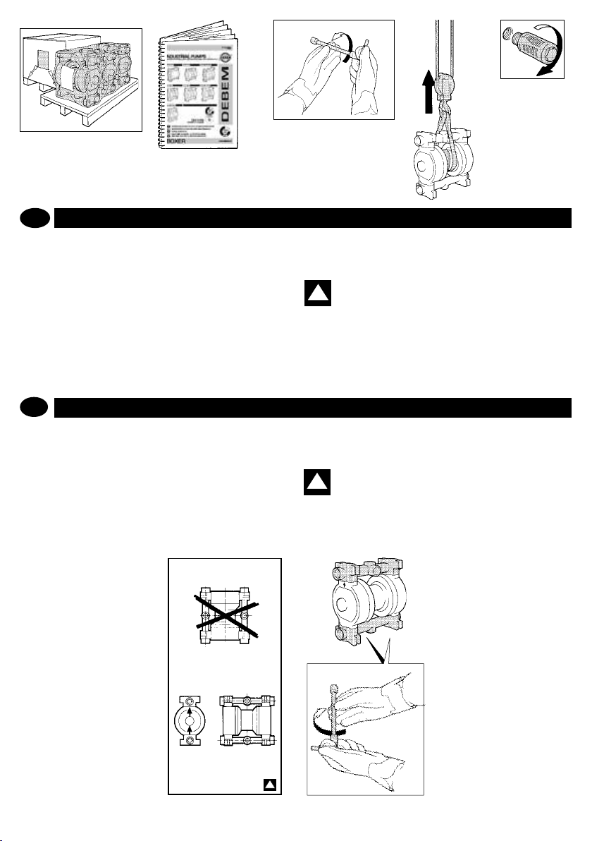
1. Depending on the size and weight, the material is forwarded
de madeira: ao receber, abrir e retirar a embalagem.
2. Retirar o manual de uso e manutenção e operar como
descrito.
3. Realizar uma vericação do aperto de todos os parafusos
da bomba;
4. Suspender a bomba com equipamentos de levantamento
adequados ao peso indicado na placa.
5. Caso a bomba tenha sido enviada com o silenciador de
descarga desmontado, providenciar a sua montagem.
packed in cardboard cases on a pallet or in a crate: on receipt
open and remove the packing.
2. Read the User and Maintenance Manual and proceed as
explained.
3. Make sure that all of the pump’s screws are well tightened.
4. Hoist the pump using suitable equipment according to the
weight shown on the plate.
5. If the pump has been forwarded with drain silencer disassembled, mount the same.
17
info@debem.it
Page 18
5
1
2
P
ATENÇÃO: o posicionamento e a xação prevista para
a bomba é horizontal, com estacas no teto ou no piso,
nos pés de suporte. O coletor de saída produto deve ser
posicionado sempre na parte superior, respeitando as
respectivas inscrições
“OUT” = SAÍDA (acima)
“IN” = ASPIRAÇÃO (abaixo) ou conforme o modelo da
bomba, controlar que as setas impressas no corpo estejam
sempre orientadas para cima.
6. Posicionar corretamente a bomba no local de instalação,
o mais próximo possível ao ponto de retirada e providenciar
GB
WARNING: Position and secure the pump horizontally
using hangers xed to the ceiling or feet resting on the
ground. The product delivery manifold must always be
positioned on the upper part according to the signs:
“OUT” = DELIVERY (up)
“IN” = INTAKE (down) or according to the pump model,
check that the arrows shown onto the casing are always
poin-ting upwards.
6. Position the pump correctly on the site chosen for installation,
3
4
a xação da estacas nos pés de suporte, com os parafusos
adequados. Prever um espaço suciente para as eventuais
futuras manutenções.
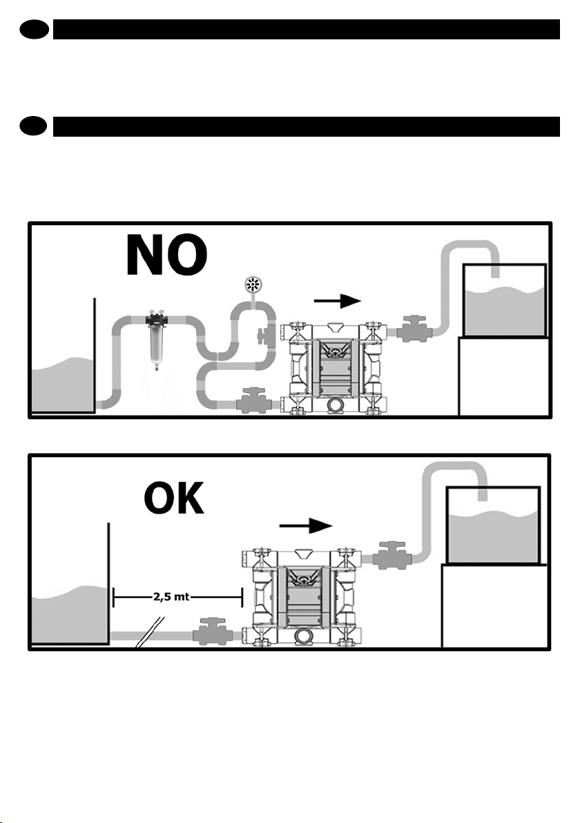
ATENÇÃO: as bombas de membrana com aspira-
!
ção negativa são inuenciadas pelos seguintes
fatores:
- viscosidade e peso especíco do uido;
- diâmetro e comprimento da aspiração. Posicionar a
bomba quanto mais próximo possível ao ponto de retirada
(em até 2,5 m) e em todo caso nunca mais longe de 5 m.
as close as possible to the point of collection and secure onto
the feet using the bolts supplied. Arrange for enough room to
carry out maintenance.
WARNING: diaphragm pumps with negative suction
!
are affected by the following factors:
- viscosity and specic weight of the uid;
- suction diameter and length.
Position the pump as close as possible to the point of
collection (within 2,5 m.) and in any case never more than
www.debem.it
OUT
IN
OK
!
6
18
Page 19
P
O diâmetro do tubo de aspiração nunca deve ser inferior
ao do engate na bomba, mas deve ser oportunamente
aumentado proporcionalmente ao aumentar da distância.
O uido a ser bombeado com aspiração negativa nunca
deve ultrapassar uma viscosidade de 5000 cps a 20 °C e
um peso especíco de 1,4 kg/l. Estes elementos podem
causar uma diminuição do desempenho e da vida útil das
membranas: PERIGO DE RUPTURA ANTECIPADA.
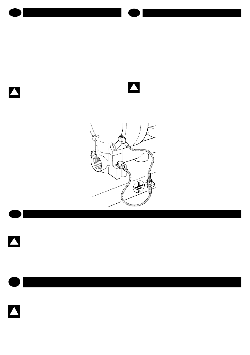
7. Se a bomba for fabricada em material condutivo e apta ao
bombeamento de uidos inamáveis, é preciso instalar um
adequado cabo de aterramento sobre cada corpo bomba:
PERIGO DE EXPLOSÃO E/OU INCÊNDIO.
ATENÇÃO: a bomba deve ser sempre aterrada inde-
!
pendente de outro órgão eventualmente conectado.
A falta de aterramento ou o aterramento incorreto
anulam os requisitos de segurança e proteção contra o
perigo de explosão.
O posicionamento está concluído.
GB
5 m. The diameter of the intake pipe must never be smaller
than the connection of the pump, but must be increased as
the distance increases. Fluid to be pumped with negative
suction must never exceed a viscosity of 5,000 cps at 20°
C and a specic weight of 1.4 Kg/l. These elements can
cause derating and reduce the duration of the diaphragm:
DANGER OF PREMATURE BREAKAGE.
7. If the pump is made from conductive materials and is suitable
for ammable products, each pump casing must be equip-ped
with a suitable earthing cable: DANGER OF EXPLOSION
AND/OR FIRE.
WARNING The pumps must always be grounded
!
irrespective of any organ to which it is connected.
Lack of grounding or incorrect grounding will
cancel the requirements for safety and protection against
the risk of explosion.
This completes positioning.
LIGAÇÃO DO CIRCUITO PRODUTO
P
Após ter realizado o posicionamento, é possível efetuar a
ligação da bomba ao circuito do produto, da seguinte forma:
ATENÇÃO: para as conexões com os coletores da
bomba, utilizar apenas junções com roscas para
!
gás cilíndricas de material compatível com o uido
a ser bombeado e com o material de construção da bomba.
EXEMPLO: bomba em PP = junção PP
bomba INOX = junção INOX
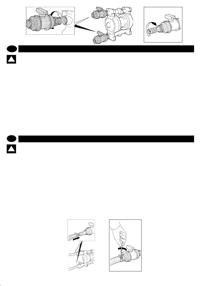
1. Instalar no coletor de saída e descarga uma válvula manual
GB
CONNECTING THE PRODUCT CIRCUIT
After positioning the pump you can now connect it to the product
circuit as follows:
WARNING: only ttings with cylindrical gas threads
in materials compatible with both the uid to be
!
pumped and the pump’s construction materials
must be used. For example:
Pump made from PP = PP tting
Stainless steel pump = stainless steel tting.
com diâmetro igual ao do engate da bomba (nunca menor) para
garantir a interceptação do uido em caso de vazamentos e/
ou futuras manutenções.
2. Providenciar a instalação das mangas para a xação dos
tubos exíveis em ambas as válvulas.
3. Em caso de linha de saída vertical com mais de 5 m, aconselhamos o uso de uma válvula de não retorno para evitar um
retorno do uido na bomba.
1. On the delivery and discharge manifold install a manual
valve of the same diameter as the pump inlet (never smaller)
to intercept the uid correctly in case of spills and/or when
servicing the pump.
2. Install the sleeves to secure the exible hoses on both valves.
3. In the event of a vertical delivery higher than 5 meters, we
advise to use a check valve to prevent the uid from returning
into the pump.
19
info@debem.it
Page 20
1
P
ATENÇÃO: os tubos de conexão com a bomba
!
devem ser de tipo FLEXÍVEL E REFORÇADO COM
ESPIRAL RÍGIDA e diâmetro nunca inferior ao engate da própria bomba. Filtros ou outros dispositivos instalados na aspiração da bomba devem ser adequadamente
dimensionados de modo a não provocar perdas de carga.
Para instalações negativas e/ou para uidos viscosos, utilizar tubos com DIÂMETRO MAIOR, sobretudo na aspiração.
É proibida a ligação DIRECTA à bomba com tubos rígidos,
metálicos (em bombas de plástico) e/ou com rosca cónica,
já que podem provocar tensões e/ou vibrações intensas
e a ruptura dos colectores e de outros componentes da
bomba. Utilize sempre juntas exíveis com ligações do
mesmo material da bomba (PP com PP, INOX com INOX).
É proibida também a utilização de substâncias de bloqueio
de roscas e/ou teon em pasta. O instalador deverá ter
em conta a centragem das ligações durante a montagem
evitando rachaduras e/ou falha das roscas.
Verique também se o possível excesso de ta no PTFE e
uma pressão de aperto excessiva não esforçam o colector
GB
WARNING: the pump must be connected with
!
FLEXIBLE HOSES REINFORCED WITH A RIGID
SPIRAL of a diameter never smaller than the pump’s
connection. The lters or other equipment installed at the
intake side must be suitably dimensioned in order to avoid
pressure drops. For negative installations and/or viscous
uids, use hoses with an OVERSIZE DIAMETER, especially
on the intake side.
Do not attach the pump DIRECTLY with rigid metal pipes (on
plastic pumps) and/or pipes with tapered thread, as they
can cause severe stress and/or vibrations and breakage
of the manifolds and other parts of the pump.
Always use exible joints with ttings made of the same
material of the pump (PP with PP, INOX with INOX)
Do not use threadlockers and/or Teon paste. The installer
must ensure that the ttings are centred during assembly to
prevent cracks and/or to prevent the threads from yielding.
Also check that any excess PTFE tape and excessive
clamping pressure does not place stress on the manifold
2
ou outros componentes da bomba.
Preste especial atenção a fenómenos de corrosão por
tensão. O material da bomba pode degradar-se por via
da acção combinada da corrosão e da aplicação de uma
carga, causando a ruptura imprevista e inesperada dos
componentes colocados sob tensão, especialmente a
temperaturas limite.
Vericar que as tubulações de conexão com a bomba
estejam internamente limpas e que não contenham
resíduos de processamento.
4. Providenciar a ligação do tubo de aspiração e saída produto
nas relativas junções, respeitando as inscrições gravadas na
bomba:
“IN” = ASPIRAÇÃO (abaixo) e
“OUT” = SAÍDA (acima)
ou respeitando as setas.
5. Providenciar a xação dos tubos com faixas apropriadas.
or other parts of the pump.
Pay particular attention to stress corrosion cracking. The
pump material may deteriorate due to the combined action
of corrosion and application of a load, which may cause
parts subjected to stress to break suddenly and unexpectedly, especially at low temperatures.
Check if the connection tubes to the pump are clean inside
and do no contain any working residue.
4. Connect the product intake and delivery hoses to their
respective ttings whilst taking into consideration the signs
on the pump:
“IN” = INTAKE (down) and
“OUT” = DELIVERY (up)
or according to that indicated by the arrows.
5. Secure the hoses using the relevant clamps.
www.debem.it
4
5
20
Page 21
P
Na aspiração da bomba, exceto a válvula de intercepção que
permite, em caso de avaria, isolar a bomba, deve-se evitar
a instalação de qualquer outro equipamento adicional (co-
nexões, junções, válvulas, ltros, etc.) que possam penalizar
as condições de aspiração da bomba e provocam a ruptura
GB
Apart from the check valve that enables cutting off the pump
if there is a fault, do not install any other components on the
pump suction (couplings, elbows, valves, lters, etc.) which
could compromise the pump suction performance and cause
the premature breakage to the membrane. The pump must be
prematura das membranas. A bomba deve ser alimentada de
forma progressiva através do uso de uma válvula e “arranque
progressivo”.
powered progressively using a “progressive start-up” valve.
21
info@debem.it
Page 22

P
ATENÇÃO: equipar as tubulações com suportes
!
adequados; AS TUBULAÇÕES devem ser sucien-
temente resistentes a ponto de não sofrer deformações por conta da aspiração. NUNCA DEVEM PESAR NA
BOMBA, DE FORMA ALGUMA e vice-versa.
6. Em caso de uso para a aspiração de tonéis (não sob o nível
do uido), a extremidade imergida do tubo de aspiração deve
ser equipada com adequada ponteira com corte transversal,
de modo a impedir que cole no fundo.
ATENÇÃO: controlar que no uido tratado não haja
!
nem possam haver partes sólidas com dimensões
elevadas ou forma prejudicial e que não haja estrangulamentos ou obstruções na entrada ou na saída
da bomba, para evitar, respectivamente, fenômenos de
cavitação e esforço do motor pneumático.
A ligação do circuito do produto está concluída.
GB
WARNING:Provide appropriate support for the
!
piping. THE PIPING MUST BE STRONG ENOUGH
TO AVOID DEFORMATION DURING THE SUCTION
PHASE AND MUST NEVER WEIGH DOWN ON THE PUMP
IN ANY WAY OR VICE VERSA.
6. If used for drum suction (not below head), the submersed
end of the intake hose must be provided with a diagonally cut
xing to prevent it from adhering to the drum bottom.
WARNING: Ascertain that the uid treated does not
!
contain or cannot contain large solids or solids of
a dangerous shape and that the intake or delivery
ports are not obstructed nor limited to avoid either cavitation or pneumatic motor strain.
Connection of the product circuit nishes here.
OK
LIGAÇÃO PNEUMÁTICA
P
Para realizar a ligação da bomba com o circuito pneumático,
proceder da seguinte forma:
ATENÇÃO: a alimentação pneumática da bomba
!
BOXER deve ser realizada com AR FILTRADO,
SECO, ISENTO DE ÓLEO E NÃO LUBRIFICADO,
com pressão rigorosamente entre 2 e 7 bar.
ATENÇÃO: nunca retirar, em nenhuma circunstân-
cia, o RESET e/ou não realizar a ligação do ar no
canal RESET.
PNEUMATIC CONNECTION
GB
To connect the pump to the pneumatic circuit, you must:
WARNING: pneumatic supply to the BOXER pumps
!
must be made using FILTERED, DRIED, NON LUBRICATED OIL FREE AIR at a pressure of not less
than 2 bars and not more than 7 bars.
WARNING: do not remove RESET for any reason
!
and/or do not con-nect the air supply to the RESET
channel.
www.debem.it
1. Retirar o adesivo do engate do ar.
2. Instalar no engate do circuito pneumático da bomba um
registro de interceptação, uma válvula de 3 vias e uma válvula
de não retorno, conforme o esquema indicado na gura.
OBS.: para medir a pressão real do ar, é necessário instalar um manômetro na ligação do ar da própria bomba,
e controlar o valor com a bomba em funcionamento.
1. Remove the adhesive sticker from the air connection.
2. Install an on-off valve, a three-way valve and a check valve on
the pneumatic circuit connection on board the pump according
to the layout shown in gure 1.
REMARK: to measure the actual air pressure, install a
pressure gauge on the air connection of the pump and
check the value while the pump is running.
22
Page 23

!
SOLO
FILTRO
ONLY FILTER
NO OLIO
NO OIL
P
3. Providenciar a ligação do tubo de alimentação de rede
com o circuito da bomba.
ATENÇÃO: utilizar tubos, acessórios e elementos
!
de controle e ajuste com características de caudal
e pressão adequadas às características da bomba,
para não determinar quedas de pressão.
Atenção: as junções com engates rápidos: a maioria
!
provoca quedas de pressão.
GB
3. Connect the supply hose from the net work to the pump
circuit.
WARNING: To avoid in pressure drops, use hoses,
!
accessories and control and regulation elements
whose delivery and pressure characteristics are
suitable to the pump’s own characteristics.
WARNING: Most snap-on ttings cause pressure
!
drops.
4. Ajustar a pressão de rede do ar comprimido de forma a
garantir, durante o funcionamento da bomba, uma pressão
NÃO INFERIOR a 2 bar e NÃO SUPERIOR a 7 bar. Para as
bombas boxer com esferas de borracha, NÃO ULTRAPASSAR
A PRESSÃO DE 5 bar. Pressões inferiores ou superiores
podem provocar problemas de funcionamento ou quebras da
bomba, vazamentos do produto e danos a pessoas e/ou coisas.
OBS.: para acionar várias bombas com um único
dispositivo de controle do ar, favor dirigir-se a
nossos técnicos.
4. Adjust the network pressure of the compressed air to guarantee
a pressure of NOT LESS THAN 2 bars AND NOT MORE THAN 7
bars when the pump is running. For BOXER pumps equipped WITH
RUBBER BALLS, DO NOT EXCEED 5 bars. Lower or higher pres
sure may cause functional problems or pump breakage, product
spills and damages to persons or objects.
REMARK: to feed more than one pump with the same air
control device, please ask our engineers.
NO OLIO
NO OIL
-
23
min 2 bar
max 7 bar
info@debem.it
Page 24

P
5. Caso se verique uma condição de bloqueio da bomba, é
preciso eliminar as causas que determinaram tal situação (ver
pág. 35) e, em seguida, para rearmar o equipamento, girar em
sentido anti-horário de ½ giro o dispositivo manual. Aguardar
que a bomba recomece a funcionar e reaparafusar o dispositivo
de rearmamento.
6. Caso se queira detectar ou visualizar o número de ciclos
da bomba, providenciar a instalação do dispositivo CONTACICLOS DEBEM, como descrito no Capítulo PEÇAS DE
GB
5. In the event that the pump stalls, whatever may have caused
the stall must be eliminated (see page 35), after which reset by
rotating the manual device by half a turn in an anti-clockwise direc
tion. Wait for the pump to re-start and re-screw the reset device.
6. If the number of pump cycles needs to be recorded or displayed,
install the DEBEM STROKE COUNTER as described in the chapter
entitled SPARE PARTS.
-
REPOSIÇÃO.
ATENÇÃO: para instalações em Zona 1, caso o
!
utilizador preveja o risco de exceder os limites
de temperatura previstos pelo presente manual, é
necessário instalar no sistema um dispositivo de proteção
que impeça o alcance da temperatura global (uido e ambiente) de 95°C para as bombas em classe T4 metálicas
ou em PVDF, ou 65°C para as bombas da mesma classe
T4 mas fabricadas em PP (polipropileno).
WARNING: For installation in Zone 1, should the
user think that the temperature limits set forth in this
!
manual may be exceeded during service, a protective
device must be installed on the system to prevent the global
temperature (uid + ambient) from reaching temperatures
higher than 95°C in the case of class T4 metallic or PVDF
pumps or 65°C for T4 class PP (polypropylene) pumps.
65
P
7. Proteger sempre a bomba contra possíveis choques, provocados acidentalmente por veículos em movimento ou materiais
diversos contundentes, que poderiam danicá-la e/ou reagir ao
contato.
8. Proteger o ambiente e as pessoas com a instalação de um
anteparo de proteção, em caso de avarias acidentais da bomba,
para a contenção e a coleta em caso de vazamento do produto:
perigo de graves danos físicos, para a saúde das pessoas e/ou
para os bens materiais.
9. Em caso de ruptura total das membranas, o uido pode entrar
no circuito pneumático, danicá-lo e sair pela descarga. Portanto,
é necessário dirigir a descarga do ar, mediante tubulação, para
uma área segura.
GB
7. Always protect the pump from possible accidental collisions with
moving objects or various blunt materials that may damage it or
react on contact with it.
8. Protect the site and the persons from accidental failures by in
stalling a protection guard to hold and collect any product leakage:
DANGER OF SERIOUS INJURIES AND DAMAGE TO HEALTH
AND/OR OBJECTS.
9. If the diaphragms are completely torn, the uid may enter the
air circuit, damaging it, and be discharged through the exhaust
port. It is therefore necessary that the air exhaust be conveyed
by pipes to a safe area.
www.debem.it
-
24
6
7
Page 25

P
COLOCAÇÃO EM SERVIÇO
O utilizador deverá sempre usar materiais compatíveis com
o líquido bombeado, conforme as condições de projeto da
própria bomba.
ATENÇÃO: está proibido o uso da bomba com
uidos não compatíveis com os materiais dos
!
componentes ou em ambiente com presença de
uidos não compatíveis.
Para colocar em serviço a bomba, agir da seguinte forma:
1. Vericar que os tubos de aspiração e saída do produto
GB
COMMISSIONING
The user must always use materials that are compatible with
the pumped liquid according to the pump’s design conditions.
WARNING: it is forbidden to use the pump with
!
uids that are not compatible with the pump’s
construction materials or in a place that contains
incompatible uids.
To commission the pump, proceed as follows:
OUT
estejam corretamente conectados (vericar as inscrições no
corpo da bomba).
“IN” = ASPIRAÇÃO (abaixo) e
“OUT” = SAÍDA (acima).
2. Vericar a correta instalação das válvulas do circuito pneumático da bomba (válvula de esfera de interceptação, válvula
de 3 vias e válvula de não retorno).
3. Abrir os registros das tubulações de aspiração e saída do
uido.
1. Make sure that the product delivery and intake hoses are
correctly connected - check the signs on the pump:
“IN” = INTAKE (down) and
“OUT” = DELIVERY (up)
2. Check that the pump’s pneumatic circuit valves are correctly
installed (on-off ball valve, three-way valve and check valve).
3. Open the uid intake and delivery valves.
IN
1
P
ATENÇÃO: nunca colocar a bomba em funcio-
!
namento com as válvulas produto (aspiração
e saída) fechadas: PERIGO DE RUPTURA DAS
MEMBRANAS.
4. Abrir a válvula de esfera de interceptação montada no
engate da bomba.
5. Abrir a válvula de 3 vias.
GB
WARNING: never start the pump with the product
!
valves (intake and delivery) closed: DANGER OF
DIAPHRAGM BREAKAGE.
4. Open the on-off ball valve mounted on the pump connection.
5. Open the three-way valve.
6. Check and regulate the network air pressure when the pump
25
2
6. Controlar e ajustar oportunamente a pressão do ar na rede
durante o funcionamento da bomba: MÍN. 2 bars MAX 7 bars;
para as bombas com esferas de borracha, máx. 5 bars.
AVISO: com pressões inferiores aos 2 bars com a
bomba em funcionamento, a bomba pode sofrer
BLOQUEIO, com pressões superiores à de limite
MÁXIMO podem ocorrer falhas e vazamentos do produto
em pressão e/ou quebras da bomba.
is running: MIN 2 bar MAX 7 bar; max 5 bar for pumps with rub
ber balls.
CAUTION: if the pressure is below 2 bars when the
pump is running, the pump may STALL. At a pressure
higher than the MAXIMUM threshold, yielding and
leakages of the product under pressure may occur and/or
the pump may break.
3
-
info@debem.it
Page 26

min 2 bar
max 7 bar
4
P
7. Caso se deseje realizar um ajuste da velocidade da bomba
em função da viscosidade do uido a ser bombeado, é possível
intervir de duas formas diferentes:
A. Ajustar a pressão de alimentação do ar de rede
B. Parcializar o volume de ar (caudal) mediante a válvula de
esfera de interceptação montada na bomba.
GB
7. To regulate the speed of the pump according to the uid
viscosity, you can operate in two ways:
A. regulate the network air pressure
B. choke the air volume (ow rate) by means of the on-off valve
mounted on the pump
5
OBS.: as bombas não ativadas têm uma capacidade
de altura de aspiração negativa que varia em função
do tipo de membrana e juntas de vedação montadas;
PARA DEMAIS INFORMAÇÕES CONTATAR O SERVIÇO DE
ASSISTÊNCIA DO FABRICANTE.
ATENÇÃO: em caso de bomba montada com as-
!
piração negativa, reduzir a velocidade da bomba
agindo na válvula de esfera do ar.
REMARK: unprimed pumps have a negative suction
head capacity that varies according to the type of dia-
phragm and packing mounted. PLEASE CONTACT THE
MANUFACTURER’S CUSTOMER ASSISTANCE SERVICE
FOR FURTHER DETAILS.
WARNING: If the pump has negative suction, reduce
!
the speed of the pump using the ball valve on the
sir supply.
6
www.debem.it
7A
26
!
7B
Page 27

P
ATENÇÃO: em caso de bombas
!
com coletor duplicado NÃO UTI-
LIZAR DOIS FLUIDOS COM VISCOSIDADE sensivelmente diferentes;
PROBLEMAS DE BLOQUEIO, DESGASTE ANTECIPADO DAS MEMBRANAS
E DO CIRCUITO PNEUMÁTICO.
8. Para parar a bomba, agir exclusiva-
mente na alimentação do ar, fechando a
válvula de 3 vias e descarregando, desta
forma, a pressão residual do sistema
pneumático da bomba.
ATENÇÃO: é proibido parar a
!
bomba em funcionamento e/ou
com o circuito pneumático em
pressão mediante o fechamento dos
registros de aspiração e/ou saída do cir-
cuito do uido: PERIGO DE BLOQUEIO
DA BOMBA, DESGASTE ANTECIPADO
E/OU RUPTURA DAS MEMBRANAS.
A cavitação, além de ser um fenômeno danoso para a bomba, é
perigoso em atmosfera potencialmente explosiva: é necessário
controlar que a bomba tenha sido corretamente
dimensionada
P
e, em caso de dúvidas, entrar em contato com a DEBEM.
ATENÇÃO: vericar que, durante o funcionamento,
não sejam produzidos ruídos anômalos. Neste
!
caso, interromper imediatamente o funcionamento
da bomba.
ATENÇÃO: controlar que no uido de saída não
haja gás; em caso positivo, interromper imediata-
!
mente o funcionamento da bomba.
ATENÇÃO: em caso de uidos com viscosidade
elevada, não usar filtros e/ou tubulações com
!
dimensões insucientes, sobretudo em aspiração;
além disso, diminuir a velocidade da bomba, parcializando
o volume de ar e deixando a pressão inalterada.
9. Após duas horas de funcionamento da bomba e depois da
sua parada correta, realizar um controle do aperto de todos
os parafusos da mesma.
GB
WARNING: In pumps with split
!
manifold, DO NOT USE TWO FLU-
IDS WITH DIFFERENT VISCOSITIES as STALL, PREMATURE DIAPHRAGM
AND PNEUMATIC CIRCUIT WEAR may
occur.
8. Only the air supply must be used to stop
the pump, by closing the three-way valve to
discharge any residual pressure from the
pump’s pneumatic circuit.
WARNING: never stop the pump
!
when it is running and/or when
the pneumatic circuit is under
pressure by closing the intake and/or de-
livery valves on the uid circuit: DANGER
OF PUMP STALLING AND PREMATURE
WEAR AND/OR BREAKAGE OF THE
DIAPHRAGM.
Besides being damaging for the pump, cavitation is dangerous
in a potentially explosive atmophere:
GB
You must ascertain that the pump has been sized correctly. In
case of doubt, please contact DEBEM.
WARNING: ascertain that no anomalous noises
occur during operation. If so, stop the pump im-
!
mediately.
WARNING: ascertain that the uid at the delivery
!
side does not contain gas. Otherwise stop the
pump immediately.
WARNING: In the case of high viscosity uids, do
!
not use under-sized lters or piping, especially on
the intake side. Furthermore, you must decrease
the pump speed by choking the volume of air whilst leaving
pressure unchanged.
9. After two hours of operation, and after stopping the pump
correctly, check that all of the bolts are tight.
27
9
info@debem.it
Page 28

sinal
de perigo
genérico
Posicionar os seguintes sinais de proibição e perigo próximo do local de instalação da bomba
perigo
material
corrosivo
perigo
material
inamável
perigo
material
explosivo
perigo
material
tóxico
perigo de
borrifos de ma-
terial líquido
incandescente
proibido
usar chamas
livres
proibido
fumar
General
Danger Sign
MANUTENÇÃO CIRCUITO PRODUTO
P
ATENÇÃO: antes de intervir na bomba e/ou antes
!
de realizar manutenções ou consertos, é neces-
sário:
A. Descarregar o produto que está sendo bombeado e fechar
as válvulas manuais de interceptação produto (aspiração e
saída).
B. deixar circular um uido de lavagem, idôneo e não inamável; em seguida, descarregar o uido de lavagem e fechar a
válvula de interceptação produto.
C – secionar a alimentação do ar mediante a válvula corres-
pondente de 3 vias e certicar-se de que não haja pressões
residuais
D – Cortar a alimentação do ar à montante;
E - Aguardar o arrefecimento da bomba por pelo menos
quinze minutos;
F. Realizar as operações necessárias, utilizando luvas de proteção e todos os outros equipamentos de proteção individuais
do caso (máscaras para o rosto, luvas, botas de segurança
etc.): perigo de projeção de uido sob pressão e queimaduras.
PRODUCT CIRCUIT MAINTENANCE
GB
WARNING: before intervening on the pump and/or
performing any maintenance or repair, you must:
!
A. discharge the product being pumped and close the product
on-off valves (both on the intake and delivery sides).
B. Circulate a suitable non-ammable washing uid then drain
it off and close the product shut-off valve.
C. Shut-off the air supply using the relevant three-way valve
whilst making sure that no residual pressure subsists.
D. Shut-off air supply upstream;
E. Wait for the pump to cool down for at least fteen minutes;
F. Perform the necessary operations while wearing protection
gloves and any other appropriate personal protection equipment (face masks, gloves, closed shoes, etc.): DANGER OF
BURNING AND EJECTION OF LIQUID UNDER PRESSURE.
Danger
Corrosive
Material
Put the following prohibition and danger signs near the place where the pump is installed
Danger
Flammable
Material
Danger
Explosive
Material
www.debem.it
Danger Toxic
Material
28
Danger
Incandescent
Liquid Sprinkles
Prohibition
on Open
Flames’ Use
A
C
÷ 0 bar
No smoking
D
E
Page 29

P
ATENÇÃO: retirar os depósitos de poeira das su-
perfícies externas da bomba de pulsações com um
!
pano umedecido com detergente neutro idôneo.
1. Desconectar os tubos de aspiração e saída do uido da
bomba.
2. Desconectar o tubo de alimentação do ar comprimido da
bomba.
GB
WARNING: remove deposits of powder from the
!
external surfaces of the pump with a cloth soaked
in suitable neutral detergents.
1. Disconnect uid intake and delivery hoses from pump.
2. Disconnect the compressed air supply pipe from the pump.
3. Disassemble and remove the pump from its place of instal-
3. Providenciar a desmontagem e a retirada da bomba do local
de instalação com equipamentos de levantamento adequados.
OBS.: consultar o esquema das peças de reposição
para as sequências de desmontagem e nova montagem da bomba para as operações descritas abaixo.
4. Realizar vericação e limpeza periódica das superfícies
internas, com um pano umedecido.
lation using suitable hoisting equipment.
REMARK: refer to the relevant spare parts table for the
order of assembly and reassembly when carrying out
the above operations.
4. Periodically control and clean the
internal surfaces with a damp cloth.
1
A. LIMPEZA E SUBSTITUIÇÃO ESFERAS E ALOJAMENTO ESFERAS
P
Para a limpeza e/ou substituição dos alojamentos das esferas
e das próprias esferas, agir da seguinte forma:
ATENÇÃO: antes de realizar esta operação, é pre-
!
ciso providenciar a limpeza externa de todas as
superfícies da bomba com um pano úmido.
A1. Desmontar os coletores de aspiração e saída, retirando
os elementos de xação.
A2. Extrair os alojamentos e as esferas e providenciar a sua
limpeza com um pano umedecido
A. CLEANING AND REPLACING THE BALLS AND BALLS SEATS
GB
To clean and/or replace the balls and ball seats, proceed as
follows:
WARNING: before carrying out this operation all
!
external surfaces of the pump must be cleaned
using a damp cloth.
A1. disassemble the intake and delivery manifolds by removing
the xing elements.
e/ou providenciar a sua substituição com peças de reposição
originais do mesmo tipo (ver esquemas peças de reposição).
A3. Vericar as condições das juntas de vedação e, se ne-
cessário,
substituí-las com peças de reposição originais, do mesmo tipo.
A2. Remove the seats and the balls and clean them with a
damp cloth and/or replace them with genuine spare parts of
the same type (see spare parts tables).
A3. Check the condition of the gasket and, if necessary, replace
with original spare parts of the same type.
29
2
3
info@debem.it
Page 30

A2
A1
P
AVISO: vericar a ausência de depósitos de qualquer natureza na bomba,
caso contrário removê-los com um
pano úmido.
A4. Montar de volta, seguindo a ordem inversa,
e apertar os parafusos de xação todos da
mesma forma.
A limpeza e/ou a substituição das esferas
e respectivos alojamentos está concluída.
Agora é possível reposicionar a bomba e
restabelecer as ligações, como indicado nos
capítulos anteriores.
B. LIMPEZA E SUBSTITUIÇÃO DAS MEMBRANAS
P
Para o bom funcionamento da bomba, e, sobretudo, para garantir os requisitos de segurança e tutela contra o risco de
explosão, é indispensável realizar os controles, as limpezas
e/ou a substituição das membranas, respeitando os prazos
indicados pela tabela.
ATENÇÃO: as membranas (em contato com o pro-
!
duto e as externas) são componentes sujeitos a
elevado desgaste. Sua vida útil é fortemente in-
uenciada pelas condições de uso e pelas solicitações
químicas e físicas. De testes realizados sobre milhares
de bombas instaladas com prevalência igual a 0 e uido
a 18º C. a duração normal ultrapassa os 100.000.000 (cem
milhões) de ciclos. Por razões de segurança, nos ambientes com perigo de explosão, é obrigatória a sua substitui-
A3
GB
CAUTION: check that there are no deposits of any kind inside the pump, and
if found remove them with a damp cloth.
A4. Reassemble by repeating the previous se-
quence in reverse order. Tighten the xing bolts
evenly.
Cleaning and/or replacement of balls and ball
seats nishes here. You can now reposition
the pump and reconnect it as described in the
previous sections.
A4
ção a cada 20.000.000 (venti milioni) di cicli.
INTERVENÇÃO
OBRIGATÓRIA
CONTROLE E
LIMPEZA INTERNA
CONTROLE DAS
MEMBRANAS
SUBSTITUIÇÃO
MEMBRANAS
Para a substituição das membranas, agir da seguinte forma:
FREQUÊNCIA DA INTERVENÇÃO n. ciclos
a cada
500.000
a cada 5
milhões
•
_ • _
_ _ •
após 20
milhões
GB
B. CLEANING AND REPLACING THE DIAPHRAGMS
For good operation of the pump and to guarantee that all the
safety and protection requirements against explosion risks have
been taken, it is indispensable that the controls, cleaning and/or
replacement of the diaphragms are carried out in accordance
with the intervals shown in the table.
WARNING: the diaphragms (in contact with the
product or the external ones) are highly subject
!
to wear. Their duration is strongly affected by the
conditions of use and by chemical and physical stress.
Fields tests carried out on thousands of pumps installed
with a head equal to 0 and with uid at 18° C have shown
that normal service like exceeds 100,000,000 (one hundred
million) cycles. For safety reasons, in environments at
risk of explosion, the diaphragms must be replaced every
www.debem.it
20,000,000 (twenty million) cycles.
OBLIGATORY
OPERATION
CONTROL AND
INTERNAL CLEANING
DIAPHRAGM CHECK
DIAPHRAGM
REPLACEMENT
OPERATION TIME (nr. of cycles)
every 500.000 every 5 milion after 20
•
_ • _
_ _ •
To replace product diaphragms proceed as follows:
30
milion
Page 31

P
ATENÇÃO: Os componentes do permutador
!
pneumático eixo incluso, foram fabricados com
materiais não especicamente resistentes aos
produtos químicos. Em caso de ruptura das membranas,
se entrarem em contato com o uido, providenciar a sua
completa substituição.
B1. Desmontar os coletores de aspiração e saída, retirando
os elementos de xação.
ATENÇÃO: o utilizador deve vericar periodica-
!
mente a ausência de depósitos de poeiras nas
GB
WARNING: The components of the pneumatic ex-
changer, including the shaft, are made from materi-
!
als that are not specically resistant to chemicals.
Should the diaphragms break and the components come
into contact with the uid, replace them completely.
B1. Disassemble the intake and delivery manifolds by removing
the xing elements.
WARNING: Periodic controls must be made to
!
ensure that there are no deposits of powder on the
P
B5. Vericar e/ou substituir as membranas em ambos os
lados da bomba, utilizando peças de reposição originais
do mesmo tipo.
AVISO: vericar que não haja depósitos de nenhum
tipo na bomba, caso contrário providenciar a retirada.
B6. Montar de volta a bomba, seguindo a ordem inversa, e
apertar os parafusos de xação todos da mesma forma.
GB
B5. Check and/or replace the diaphragms on both sides of the
pump with original spare parts of the same type.
CAUTION: ascertain that the inner part of the pump is
free from all types of deposits,and if they are present
proceed with their removal.
B6. Reassemble the pump following the disassembly sequence
described earlier in reverse order. Tighten the xing bolts evenly.
superfícies internas e eventualmente realizar uma cuidadosa limpeza com pano úmido.
B2. Retirar eventuais depósitos das superfícies internas com
um pano umedecido.
B3. Desmontar os dois corpos da bomba, retirando os para-
fusos de xação.
B4. Retirar a tampa de bloqueio membranas de ambos os
circuitos.
internal surfaces and, if necessary, they must be cleaned
with a damp cloth.
B2. Remove any deposits on the internal surfaces with a
damp cloth.
B3. Disassemble the two pump casings by removing the x-
ing screws.
B4. Remove the external diaphragm locking cap from both
circuits.
ATENÇÃO: caso a bomba deva ser enviada de volta
ao fabricante ou a um centro de assistência, deverá
!
ser esvaziada do produto e oportunamente lavada
e tratada, antes do envio.
A substituição das membranas é assim terminada; será,
portanto, possível reposicionar a bomba e restabelecer
todos os engates e ligações, como indicado nos capítulos
anteriores.
WARNING: Should the pump be returned to the
manufacturer or to a service center, you must rst
!
empty it out completely. If toxic, noxious or other
types of dangerous products have been used, the pump
must be suitably treated and washed before it is sent.
Replacing the diaphragms nishes here. You can now
reposition the pump and reconnect it as described in the
previous sections.
B5
31
B6
info@debem.it
Page 32

MANUTENÇÃO DO CIRCUITO DE AR
P
ATENÇÃO: antes de intervir no amortecedor de
!
pulsações e/ou antes de realizar manutenções ou
consertos, é necessário:
A. Descarregar o produto que está sendo bombeado e fechar
as válvulas manuais de interceptação produto.
B. deixar circular um uido de lavagem, idôneo e não inamável; em seguida, descarregar o uido de lavagem e fechar
a válvula de interceptação produto.
AIR CIRCUIT MAINTENANCE
GB
WARNING: before intervening on the pump and/or
performing any maintenance or repair, you must:
!
A. discharge the product being pumped and close the product
on-off valves (both on the intake and delivery sides).
B. Circulate a suitable non-ammable washing uid then drain
it off and close the product shut-off valve.
C. Secionar a alimentação do ar mediante a válvula corre-
spondente de 3 vias e certicar-se de que não haja pressões
residuais;
D. Cortar a alimentação do ar à montante;
E. Usar os equipamentos de proteção individual idôneos para
a operação (máscaras para o rosto, luvas, botas de segurança,
aventais etc.): PERIGO DE PROJEÇÃO DO FLUIDO SOB
PRESSÃO.
C. Shut-off the air supply using the relevant three-way valve
whilst making sure that no residual pressure subsists.
D. Shut-off air supply upstream;
E. Wear suitable individual protective devices before interven-
ing: goggles/masks, gloves, closed shoes, aprons, and others):
DANGER OF FLUID EJECTION UNDER PRESSURE.
÷ 0 bar
A
C
P
ATENÇÃO: antes de desconectar o tubo de alimentação do ar ou a junção, providenciar a limpeza
externa das superfícies da bomba. Antes de recolocar
a bomba em funcionamento, certicar-se sempre da ausência
de poeira no distribuidor pneumático.
1. Desconectar os tubos de aspiração e saída do uido da bomba.
2. Desconectar o tubo de alimentação do ar comprimido da
GB
WARNING: Before removing the air supply pipe
!
or tting, clean the external surfaces of the pump.
Before restarting the pump, ensure that no powder
has entered the pneumatic distributor.
1. Disconnect uid intake and delivery hoses from pump.
2. Disconnect the compressed air supply pipe from the pump.
1
www.debem.it
D
bomba.
3. Providenciar a desmontagem e a retirada da bomba do local
de instalação com equipamentos de levantamento adequados.
OBS.: consultar o esquema das peças de reposição
para as sequências de desmontagem e nova monta
gem da bomba para as operações descritas abaixo.
3. Disassemble and remove the pump from its place of instal-
lation using suitable hoisting equipment.
REMARK: refer to the relevant spare parts table for the
order of assembly and reassembly when carrying out
the above operations.
2
3
32
E
-
Page 33

A. SUBSTITUIÇÃO DO PERMUTADOR PNEUMÁTICO MICROBOXER
P
Para a substituição do permutador pneumático das bombas
MICROBOXER, agir da seguinte forma:
ATENÇÃO: caso a bomba deva ser enviada de volta
!
ao fabricante ou outro centro de assistência, antes
deverá ser esvaziada do produto. Em caso de produtos tóxicos, nocivos ou perigosos para a saúde, a bomba
deve ser oportunamente tratada e lavada antes do envio.
A. REPLACING THE MICROBOXER PNEUMATIC EXCHANGER
GB
To replace the pneumatic exchanger in MICROBOXER pumps
you must:
WARNING: Should the pump be returned to the
!
manufacturer or to the service center, you must
empty it out completely. If toxic, noxious or other
types of dangerous products have been used, the pump
must be suitably treated and washed before it is sent.
A1. Desmontar os coletores de aspiração e saída, retirando
os elementos de xação.
A2. Desmontar os dois corpos da bomba, retirando os para-
fusos de xação.
A3. Retirar a tampa de bloqueio membranas de ambos os
circuitos.
A4. Extrair as membranas de ambos os lados da bomba.
A1. Disassemble the intake and delivery manifolds by removing
their xing elements.
A2. Disassemble the two pump casings by removing the rel-
evant xing screws.
A3. Remove the external diaphragm locking cap from both
the circuits.
A4. Remove the diaphragms from both sides of the pump.
A1
A2
P
A5. Extrair o casquilho de comando pneumático do corpo
central.
A6. Desparafusar a tampa e extrair o distribuidor monoestável
do ar.
A7. Substituir o casquilho de comando com o eixo de ligação e
o distribuidor monoestável com uma peça de reposição original
e mesmas características.
GB
A5. Extrair o casquilho de comando pneumático do corpo
central.
A6. Desparafusar a tampa e extrair o distribuidor monoestável
do ar.
A7. Substituir o casquilho de comando com o eixo de ligação e
o distribuidor monoestável com uma peça de reposição original
e mesmas características.
A3
ATENÇÃO: os permutadores pneumáticos não devem ser abertos para evitar a montagem incorreta
!
e consequente mau funcionamento da bomba.
A8. Montar de volta a bomba, seguindo a ordem inversa, e
apertar os parafusos de xação todos da mesma forma.
A substituição do permutador pneumático da MICROBOXER é assim terminada; será, portanto, possível reposicionar a bomba e restabelecer todos os engates e ligações,
como indicado nos capítulos anteriores.
ATENÇÃO: os permutadores pneumáticos não
devem ser abertos para evitar a montagem incor-
!
reta e consequente mau funcionamento da bomba.
A8. Montar de volta a bomba, seguindo a ordem inversa, e
apertar os parafusos de xação todos da mesma forma.
A substituição do permutador pneumático da MICROBOXER é assim terminada; será, portanto, possível reposicionar a bomba e restabelecer todos os engates e ligações,
como indicado nos capítulos anteriores.
A4
A5
33
A6
info@debem.it
Page 34

B. SUBSTITUIÇÃO DO PERMUTADOR PNEUMÁTICO COAXIAL
P
Todas as bombas BOXER, com exceção da MICROBOXER,
trazem um permutador pneumático coaxial; para a sua substituição, agir da seguinte forma:
ATENÇÃO: caso a bomba deva ser enviada de volta
!
ao fabricante ou outro centro de assistência, antes
deverá ser esvaziada do produto. Em caso de produtos tóxicos, nocivos ou perigosos para a saúde, a bomba
deve ser oportunamente tratada e lavada antes do envio.
GB
B. REPLACING THE COAXIAL PNEUMATIC EXCHANGER
All BOXER pumps, with the exception of MICROBOXER
pumps, have a coaxial pneumatic exchanger; to replace it
proceed as follows:
WARNING: Should the pump be returned to the
manufacturer or to a service center, you must empty
!
it out completely. If toxic, noxious or other types of
dangerous products have been used, the pump must be
suitably treated and washed before it is sent.
B1. Desmontar os coletores de aspiração e saída, retirando
os elementos de xação.
B2. Desmontar os dois corpos da bomba, retirando os para-
fusos de xação.
B3. Retirar a tampa de bloqueio membranas de ambos os
circuitos.
B4. Extrair as membranas de ambos os lados da bomba.
B1. Disassemble the intake and delivery manifolds by removing
their xing elements.
B2. Disassemble the two pump casings by removing the rel-
evant xing screws.
B3. Remove the external diaphragm locking cap from both
the circuits.
B4. Remove the diaphragms from both sides of the pump.
B1
B2
P
B5. Desmontar o permutador pneumático retirando os elementos
de xação.
B6. Substituir o permutador e o eixo de conexão com uma peça de
reposição original, com as mesmas características.
B6.1 Nas bombas com corpo central equipado com dispositivo de
rearmamento manual, o permutador pneumático deve ser inserido
orientando-o de forma que o chanfro esteja em direção do duto de
rearmamento.
B7. Montar de volta a bomba, seguindo a ordem inversa, e apertar
os parafusos de xação todos da mesma forma.
A substituição do permutador pneumático coaxial é assim
terminada; será, portanto, possível reposicionar a bomba e
restabelecer todos os engates e ligações, como indicado nos
capítulos anteriores.
GB
B5. Disassemble the pneumatic exchanger by removing the
relevant xing elements.
B6. Replace the exchanger and the connection shaft with original
spare parts having the same characteristics.
B6.1 For pumps with manual reset on the main casing, the air
exchanger must be placed so that the reference bevel is turned
towards the resetting duct.
B5
B6
B7. Reassemble the pump according to the previously described
sequence but in reverse order and tighten the xing bolts evenly.
Replacement of the coaxial pneumatic exchanger nishes
here. You can now reposition the pump and reconnect it as
described in the previous sections.
B3
ATENÇÃO: os permutadores pneumáticos não devem
ser abertos para evitar a montagem incorreta e conse
!
quente mau funcionamento da bomba.
WARNING: to avoid incorrect reassembly and subseg
!
uent malfunction of the pump the coaxial pneumatic
exchangers must not be open.
B6.1
B4
-
-
B7
www.debem.it
34
Page 35

BUSCA AVARIAS
P
As indicações a seguir são reservadas unicamente a técnicos
de manutenção qualicados e autorizados.
Em caso de anomalia e para solucionar eventuais maus fun-
cionamentos, servir-se destas indicações para identicar a
anomalia.
TROUBLESHOOTING
GB
The following instructions are intended excluvively for authorised skilled maintenance engineers. In event of abnormal
behaviour and in orer to x faults, please refer to the following
trobleshooting instructions.
DEFEITO
P
1 A bomba não arranca. 1.1 Circuito sem ar.
GB
PROBLEM
1.The pump does not start 1.1 No air in the circuit.
POSSÍVEL CAUSA SUGESTÃO
1.2 Insuciência de pressão
do ar.
1.3 Insuciência de caudal.
do ar.
1.4 Válvula de comando
danicada.
1.5 Saída ou aspiração
da bomba fechada.
1.6 Permutador pneumático
bomba danicado.
1.7 Membrana quebrada.
1.8 Bomba bloqueada.
POSSIBLE SOURCE ADVICE
1.2 Insufcient air pressure.
1.3 Insufcient air ow rate.
1.4 Damaged control valve.
1.5 Pump intake or delivery
closed.
1.6 Pneumatic exchanger
damaged.
1.7 Broken diaphragm.
1.8 Pump stalled.
ATENÇÃO: para operações mais importantes, contatar o serviço de ASSISTÊNCIA DEBEM; nossos
!
técnicos lhes prestarão auxílio o quanto antes.
WARNING: For more serious problems, we strongly
oraccomend that you contact the DEBEM SERVICE
!
DEPARTMENT; our engineers will provide you as-
sistance as quickly as possible.
1.1a Controlar o circuito, os registros e os engates.
1.2a Ajustar a pressão no redutor especíco.
1.3a Controlar que os tubos e os acessórios tenham passa-
gens adequadas.
1.4a Vericar e substituir.
1.5a Soltar os tubos de saída e de aspiração e vericar o fun-
cionamento da bomba.
1.6a Substituir o permutador; controlar se há gelo na descarga do ar. Se houver, tomar providências. Ver parágrafo alimentação do ar.
1.7a Controlar se sair ar do tubo de entrada do produto; em
caso armativo, substituir a membrana.
1.8a Rearmar (ver pág. 24)
1.1a Check circuit, valves and connections.
1.2a Adjust pressure on the relevant reducer.
1.3a Check that piping and accessories have suitable pas-
sage.
1 4a Check and replace.
1.5a Disconnect intake and delivery hoses and check if the
pump starts.
1.6a Replace exchanger; check whether the air discharge is
ob- structed by ice. If so, clear it. See air supply paragraph.
1.7a Check if any air comes out from the product delivery
pipe. If so, replace diaphragm.
1.8a Reset (page 24).
DEFEITO
P
2. A bomba funciona mas
não bombeia.
PROBLEM POSSIBLE SOURCE ADVICE
GB
2.The pump runs but does
not pump
POSSÍVEL CAUSA SUGESTÃO
2.1 As esferas não fecham..
2.2 Altura de aspiração
excessivamente elevada.
2.3. Fluido excessivamente
viscoso.
2.4. Aspiração obstruída.
2.1 The balls do not close.
2.2 Intake too high.
2.3 Fluid is too viscous.
2.4 Intake side is obstructed.
2.1a Desmontar os coletores e limpar os alojamentos ou sub-
stituir as esferas e respectivos alojamentos.
2.2a Reduzir a altura de aspiração.
2.3a Instalar tubos maiores, sobretudo em aspiração, e dimi-
nuir os ciclos da bomba.
2.4a Controlar e limpar.
2.1a Disassemble the manifolds and clean the ball seats or re
place both balls and their seats.
2.2a Reduce intake height.
2.3a Install larger piping especially on the intake side and
decrease the pump cycles.
2.4a Check and clean.
35
info@debem.it
Page 36

DEFEITO
P
3 A bomba funciona com
ciclos lentos.
4 A bomba funciona de forma irregular.
PROBLEM POSSIBLE SOURCE
GB
3 Pump cycles are slow.
4 Pump functions irregularly
DEFEITO
P
5 A bomba bloqueia-se. 5.1 A aspiração obstrui-se
PROBLEM POSSIBLE SOURCE
GB
5. The pump stalls 5.1 Intake obstructs during
DEFEITO
P
6 A bomba não oferece o
caudal indicado na tabela.
POSSÍVEL CAUSA
3.1. Fluido excessivamente
viscoso.
3.2 Tubulação de saída obstruída.
3.3. Aspiração obstruída.
4.1 Permutador pneumático
interno desgastado ou com
defeito.
4.2 Eixo desgastado.
4.3 Gelo na descarga.
4.4 Falta volume de ar.
4.5 Permutador interno sujo.
3.1 Fluid is too viscous.
3.2 Delivery hose is ob-
structed.
3.3 Intake is obstructed.
4.1 Internal pneumatic ex-
changer is worn or faulty.
4.2 Shaft is worn.
4.3 Ice on discharge gate.
4.4 Lack of air ow.
4.5 Internal exchanger dirty.
POSSÍVEL CAUSA
durante o funcionamento.
5.2 Ar sujo, cheio de condensado ou óleo.
5.3 Volume ou pressão do ar
insuciente.
5.4 Distribuidor com defeito.
5.5 Não foi respeitado o pro-
cedimento de interrupção
funcionamento.
operation.
5.2 Dirty air, containing condensation or oil.
5.3 Insufcient air ow or
pressure.
5.4 Faulty distributor.
5.5 Stop procedure not com-
plied with.
POSSÍVEL CAUSA
6.1 O tubo de aspiração pro-
duto está mal conectado.
6.2 Tubulações obstruídas.
6.3. Fluido excessivamente
viscoso.
6.4 As esferas não fecham.
6.5 Volume do ar insucien-
te.
www.debem.it
SUGESTÃO
3.1a Nenhuma solução.
3.2a Controlar e limpar.
3.3a Controlar e limpar.
4.1a Substituir o permutador pneumático.
4.2a Substituir o permutador pneumático.
4.3a Desumidicar e ltrar o ar.
4.4a Controlar todos os acessórios de controle ar, especialmente os engates rápidos.
4. 5a Substituir.
ADVICE
3.1a No remedy.
3.2a Check and clean.
3.3a Check and clean.
4.1a Replace pneumatic exchanger.
4.2a Replace pneumatic exchanger.
4.3a Dehumidify and lter air.
4.4a Check all air control devices and in particular Snap-On
couplings.
4.5a Replace.
SUGESTÃO
5.1a Substituir o tubo de aspiração.
5.2a Vericar a linha do ar.
5.3a Controlar a pressão com um manômetro instalado na
bomba e com a bomba em funcionamento: ver pág. 24. Se a
pressão, naquele ponto, for excessivamente baixa em relação
à pressão de rede, controlar todos os engates do ar, especialmente os de tipo rápido. Controlar que todos os dispositivos
de controle ar tenham caudal suciente. ATENÇÃO: Nos 90%
dos casos, os bloqueios dependem dos engates rápidos.
5.4a Substituir.
5.5a Respeitar o procedimento de interrupção funcionamento.
ADVICE
5.1a Replace intake hose.
5.2a Check air line.
Check pressure using a pressure gauge installed on the pump
5.3a
when it is running: see g. 2 page 24. if the pressure at that point is
too low in relation to the network pressure, check all air ttings, espe
cially snap-on ones. Check if all air control devices have sufcient ow
rate. WARNING: in 90% of cases, stall occurrences are caused by
snap-on ttings.
5.4a Replace.
5.5a Comply with stop procedure.
SUGESTÃO
6.1a Controlar.
6.2a Controlar e limpar.
6.3a Instalar tubos maiores, sobretudo em aspiração, e dimi-
nuir os ciclos da bomba.
6.4a Desmontar os coletores e limpar os alojamentos ou substituir as esferas e respectivos alojamentos.
6.5a Controlar a pressão com um manômetro instalado na
bomba e com a bomba em funcionamento: ver g. 2 pág. 24.
Se a pressão, naquele ponto, for excessivamente baixa em relação à pressão de rede, controlar todos os engates do ar, especialmente os de tipo rápido. Controlar que todos os disposi-
tivos de controle ar tenham caudal suciente. ATENÇÃO: Nos
90% dos casos, os bloqueios dependem dos engates rápidos.
36
-
Page 37

PROBLEM POSSIBLE SOURCE
GB
6. Pump does not distributedelivery value stated
on table
COLOCAÇÃO FORA DE SERVIÇO
P
Em caso de longos períodos de inatividade da bomba, agir
da seguinte forma:
ATENÇÃO: descarregar o uido ainda presente
!
na bomba. Providenciar lavagem e tratamento
internos adequados, deixando circular um uido
detergente não inamável, compatível com os materiais
da bomba: perigo de incêndio e de lesões, danos à saúde
e/ou morte.
1. Providenciar uma lavagem interna, com produtos idôneos
ao tipo de uido bombeado.
2. Fechar os registros da aspiração e da entrada do uido
montados na bomba.
6.1 Product intake hose is
badly connected.
6.2 Piping is clogged.
6.3 Fluid is too viscous.
6.4 Balls do not close prop-
erly.
6.5 Insufcient air ow.
ADVICE
6.1a Check.
6.2a Check and clean.
Install larger piping especially on the intake side and
6.3a
decrease pump cycles.
6.4a Disassemble the manifolds and clean the seats or both
the balls and the ball seats.
6.5a Check pressure using pressure gauge installed on th-
epump when it is running: see g. 2 page 24. if the pressureat
that point is too low in relation to network pressure, checkall
the air ttings, especially snap-on ones. Check if all aircontrol devices have a sufcient ow rate. WARNING: in90% of
cases, stall occurrences are caused by snap-onttings.
3. Fechar a alimentação do ar com a válvula de 3 vias; desta
forma, a pressão residual será descarregada.
4. Se desejar guardar no depósito a bomba, é necessário:
ATENÇÃO: o eventual armazenamento deve ser
!
realizado em ambiente fechado e protegido, com
temperaturas entre 5 e 45°C, e grau de umidade
não superior a 90%.
5. Caso a bomba tenha permanecido inativa por longos períodos, é oportuno deixar circular água limpa por alguns minutos
antes de ser recolocada em funcionamento, para evitar depósitos e incrustações.
GB
DECOMISSIONING
Should the pump remain inactive for long periods, proceed
as follows
WARNING: Discharge any residual uid from the
!
pump. In case of dangerous, toxic uids and/or
otherwise noxious products, wash and treat as
suitable:danger of injuries, damage to health and/or death.
1. Wash internally using products suitable for to the uid be-
ing pumped.
2. Close the uid intake and delivery valves mounted on the
pump.
3. Close the air supply using the three-way valve; this will
discharge any residual pressure.
4. If you want to store the pump in the warehouse, you must
respect the following:
WARNING: Storage must be in a closed and pro-
!
tected environment at temperatures ranging from
5 to 45°C, and a humidity level not above 90%.
5. If the pump was in disuse for a long period of time, circulate
clean water through it for some minutes before restarting it to
avoid incrustations.
37
info@debem.it
Page 38

ELIMINAÇÃO E DEMOLIÇÃO
P
A bomba BOXER não é fabricada com materiais ou peças
perigosas; em todo caso, no nal da vida útil da mesma, para
a correta eliminação é preciso agir da seguinte forma:
ATENÇÃO: descarregar o uido ainda presente na
!
bomba. Em caso de uidos perigosos, tóxicos e/
ou danosos para a saúde, providenciar lavagem e
tratamento adequados: perigo de lesões, danos à saúde
e/ou morte.
1. Desconectar a alimentação pneumática da bomba.
GB
DEMOLITION AND DISPOSAL
The BOXER pump does not contain dangerous parts; however,
when they are worn out, they must be disposed of in the following manner.
WARNING: Discharge any residual uid from the
!
pump. In case of dangerous, toxic uids and/or
otherwise noxious products, wash and treat as
suitable: danger of injuries, damage to health and/or death.
1. Disconnect pneumatic supply from pump.
PEÇAS DE REPOSIÇÃO
P
A seguir, indicamos as peças de reposição para cada modelo de bomba BOXER.
No ato do pedido das peças de reposição, devem ser indicados os dados a seguir:
2. Desmontar a bomba do local de instalação.
3. Separar os componentes por tipologia (ver código de com-
posição da bomba).
ATENÇÃO: para a eliminação, favor dirigir-se a
empresas especializadas com as devidas auto-
!
rizações, prestando atenção para não dispersar
no ambiente componentes grandes ou pequenos que
possam causar poluição, acidentes ou danos diretos e/
ou indiretos.
2. Disassemble and remove the pump from its position.
3. Separate elements according to type (see the pump’s
composition codes).
WARNING: For disposal please contact specialized
!
disposal businesses and make sure that no small
or large components are dispersed in the environment which may cause pollution, accidents or direct and/
or indirect damage.
Matrícula
Tipo bomba
GB
SPARE PARTS
Here is a list of spare parts for the BOXER PUMPS.
When ordering spare parts, you must mention the following items:
Página Quantidade
Code
Type of pump
www.debem.it
Page Quantity
38
Detalhe
Item
Page 39

GRUPO AJUSTE AR
P
AIR ADJUSTMENT KIT
GB
1
2
Ajuste Ar
Air adjustment
ESQUEMA DE MONTAGEM CONJUNTO ALIMENTAÇÃO AR
P
O CONJUNTO ALIMENTAÇÃO AR é fornecido com ltro,
junções e tubulação ar.
ATENÇÃO: a alimentação pneumática das bombas
!
deve ser realizada com AR ISENTO DE ÓLEO, SECO
e já FILTRADO.
1. Providenciar a xação na parede da armação de suporte e
do grupo de ltragem.
2. Providenciar a montagem na bomba do registro de interceptação.
3. Executar a montagem das junções rápidas fornecidas no
AIR SUPPLY KIT ASSEMBLY LAYOUT
GB
The AIR SUPPLY KIT comes complete with lter, ttings and
air hose.
WARNING: the pump must be supplied with OIL-
!
LESS, DRIED and FILTERED AIR.
1. Afx to the wall the supporting bracket and the lter assembly.
2. Assemble the on-off valve onto the pump.
3. Mount the snap couplings on the lter assembly and on the
pump cock.
6
5
4
6
3
grupo de ltragem e no registro da bomba.
4. Realizar a conexão do tubo do ar entre o ltro e a bomba nos
engates correspondentes, empurrando-o até o m.
5. Realizar a conexão da linha de alimentação do ar no furo
do ltro.
6. O ajuste da pressão de alimentação do ar no ltro regula-
dor deve estar entre 2 e 7 bars e realizado com a bomba em
funcionamento.
A montagem do CONJUNTO DE ALIMENTAÇÃO AR está
concluída.
4. Connect the air hose between the lter and the pump and
insert well on the special ttings.
5. Connect the air supply onto the lter hole.
6. The air supply pressure on the regulator lter must be
between 2 and
7 bar and carried out when the pump is running.
The AIR SUPPLY KIT is nished here.
POS.
POS.
1
2
3
4
5
6
P
DESCRIÇÃO DESCRIPTION
Filtro redutor
Estaca de xação
Manômetro
Tubo Elaston 5 m
Registro
Junções
GB
Reducing lter
Fixing clamp
Ammeter
5-m Elaston hose
Cock
Fittings
Qde
Q.ty
grupo ajuste ar
adjustment kit
Ajuste ar
Air adjustment
39
1
3
2
4
3
6
info@debem.it
Page 40

GRUPO CONTA-CICLOS
P
STROKE COUNTER KIT
GB
3
3
1 2
ESQUEMA DE MONTAGEM CONJUNTO CONTA-CICLOS
P
O CONJUNTO CONTA-CICLOS é fornecido completo de pressóstato, eventuais junções e esfera.
ATENÇÃO: esta operação deve ser realizada com
!
a bomba parada e isolada da fonte de alimentação
e do produto.
1. Desmontar e retirar o RESET.
2. Inserir a esfera no furo do canal do RESET; com um punção
adequado, chanfrar o alojamento da esfera.
3. Providenciar a montagem do pressóstato com eventual junção.
GB
WIRING DIAGRAM STROKE COUNTER KIT
THE STROKE COUNTER KIT is supplied complete with a pressure
switch, any ttings required and a ball.
WARNING: this operation must be performed with the
pump at a standstill and disconnected from the power
!
supply and the product.
1. Disassemble and remove the RESET.
2. Insert the ball into the hole of the RESET channel; caulk the seat
of the ball using a suitable punch.
3. Fit the pressure switch using a suitable tting.
4. Retirar a pipeta e realizar a ligação dos contatos elétricos
para pôr em remoto o sinal para a contagem.
5. Montar de volta a pipeta.
6. Para realizar o ajuste da sensibilidade de intervenção do
pressóstato, retirar a tampa e com uma chave de fenda girar o
parafuso de ajuste.
HORÁRIO = maior pressão de intervenção;
ANTI-HORÁRIO = menor pressão de intervenção.
A montagem do CONJUNTO CONTA-CICLOS está concluída.
4. Ret the pipette.
5. Remove the pipette and connect the electrical contacts to remote
control the counting signal.
6. To adjust the sensitivity of the pressure switch, remove the cap and
rotate the adjustment screw using a
screwdriver.
CLOCKWISE = more pressure;
ANTI-CLOCKWISE = less pressure
This completes assembly of the STROKE COUNTER KIT.
POS.
POS.
1
2
3
P
DESCRIÇÃO DESCRIPTION
Pressóstato
Esfera
Junções
GB
Pressure Switch
Ball
Fittings
Q.de
Q.ty
www.debem.it
40
Page 41

BOXER15 PLASTICO
1
3
3
4
4
5
5
8
8
9
9
10
10
11
11
1213
14
14
1516
17
17
17
17
19
2022
23
26
26
282829
29
P
BOXER15 PLASTIC
GB
POSIÇÃO
POSITION
1
3
4
5
8
9
10
11
12
13
14
15
16
17
19
20
22
23
26
28
29
DESCRIÇÃO DESCRIPTION
Monobloco central
Corpo bomba
Coletor
Alojamento esfera
Disco interno
Anilha belleville
Tampa
Esfera
Membrana interna
Membrana externa
Porca quadrada
Filtro silenciador
Anel de retenção
Junta de ved. aloj. esfera
Permutador pneumático
Parafusos
Tampa descarga ar
Porca
Parafusos para coletor
Parafuso corpo bomba
Anilha
Central Housing
Pump Casing
Deliv. And Suct. Manifold
Ball Seat
Internal Cap
Belleville Washer
External Cap
Ball
Internal Diaphragm
External Diaphragm
Bolt
Silencer Filter
Stop Ring
O-Ring
Pneumatic Exchanger
Screw
Air Exhaust Cover
Bolt
Manifold Screw
Pump Casing Screw
Flat Washer
41
Quantidade
Quantity
info@debem.it
Page 42

MICROBOXER PLASTICO
P
17a
5b
11
5
17
14
26
14
5b
11
17
5
17a
MICROBOXER PLASTIC MADE
GB
17a
5b
28
29
4
3
10
13
12
9
8
16
1
16
44
9
12
13
10
8
7
22
20
3
41
42
43
4
29
28
11
5
17
14
26
14
5b
11
17
5
17a
POSIÇÃO
POSITION
1
3
4
5
5b
6
7
8
9
10
11
12
13
14
16
17
17a
20
22
26
28
29
41
42
43
44
www.debem.it
DESCRIÇÃO DESCRIPTION
Monobloco central
Corpo bomba
Coletor
Alojamento esfera
Gaiola guia esfera
Eixo de ligação
Silenciador
Disco interno
Anilha belleville
Tampa
Esfera
Membrana interna
Membrana externa
Porca quadrada
Anel de retenção
Junta de ved. aloj. esfera inf.
Junta de ved. aloj. esfera sup.
Parafuso tampa descarga ar
Tampa descarga ar
Parafuso corpo bomba
Parafusos para coletor
Anilha
Spola
Junta de vedação tampa spola
Tampa spola
Casquilho de comando
Quantidade
Quantity
Central block
Pump casing
Manifold
Ball seat
Ball runner cage
Connection shaft
Silencer
Internal cap
Belleville washer
Cap
Ball
Internal diaphragm
External diaphragm
Square nut
Stop ring
Ball seat packing low.
Ball seat packing up
Ait exhaust lid screw
Ait exhaust cover
Pump casing screw
Manifold screw
Washer
Shuttle
Shuttle plug gasket
Shuttle plug
Control bushing
42
Page 43

MICROBOXER ALUMINIO
P
17a
5b
11
5
17
14
3
29
26
5b
11
17
5
17a
POSIÇÃO
POSITION
1
3
4
5
5b
6
7
8
9
10
11
12
13
14
16
17
17a
20
22
26
28
29
41
42
43
44
Monobloco central
Corpo bomba
Coletor
Alojamento esfera
Gaiola guia esfera
Eixo de ligação
Silenciador
Disco interno
Anilha belleville
Tampa
Esfera
Membrana interna
Membrana externa
Porca quadrada
Anel de retenção
Junta de ved. aloj. esfera inf.
Junta de ved. aloj. esfera sup.
Parafuso tampa descarga ar
Tampa descarga ar
Parafuso corpo bomba
Parafusos para coletor
Anilha
Spola
Junta de vedação tampa spola
Tampa spola
Casquilho de comando
MICROBOXER ALUMINIUM
GB
28
29
4
12
9
16
1
44
16
9
12
13
10
8
6
22
20
14
14
10
13
8
41
7
29
28
DESCRIÇÃO DESCRIPTION
Central block
Pump casing
Manifold
Ball seat
Ball runner cage
Connection shaft
Silencer
Internal cap
Belleville washer
Cap
Ball
Internal diaphragm
External diaphragm
Square nut
Stop ring
Ball seat packing low.
Ball seat packing up
Ait exhaust lid screw
Ait exhaust cover
Pump casing screw
Manifold screw
Washer
Shuttle
Shuttle plug gasket
Shuttle plug
Control bushing
17a
5b
11
5
17
3
29
26
14
5b
11
17
5
42
43
4
17a
Quantidade
Quantity
43
info@debem.it
Page 44

MICROBOXER AISI 316
17a
P
17a
5b
11
5
17
14
3
26
29
5b
11
17
5
17a
POSIÇÃO
POSITION
1
3
4
5
5b
6
7
8
9
10
11
12
13
14
16
17
17a
18
20
22
26
27
28
29
41
42
43
44
www.debem.it
28
29
4
27
18
1
44
9
16
6
8
12
13
10
14
18
27
DESCRIÇÃO DESCRIPTION
Monobloco central
Corpo bomba
Coletor
Alojamento esfera
Gaiola guia esfera
Eixo de ligação
Silenciador
Disco interno
Anilha belleville
Tampa
Esfera
Membrana interna
Membrana externa
Porca quadrada
Anel de retenção
Junta de ved. aloj. esfera inf.
Junta de ved. aloj. esfera sup.
Tampa
Parafuso tampa descarga ar
Tampa descarga ar
Parafuso corpo bomba
Junta de vedação tampa coletor
Parafusos para coletor
Anilha
Spola
Junta de vedação tampa spola
Tampa spola
Casquilho de comando
MICROBOXER AISI 316
GB
13
12
8
9
16
Central block
Pump casing
Manifold
Ball seat
Ball runner cage
Connection shaft
Silencer
Internal cap
Belleville washer
Cap
Ball
Internal diaphragm
External diaphragm
Square nut
Stop ring
Ball seat packing low.
Ball seat packing up
Manifold cap
Ait exhaust lid screw
Ait exhaust cover
Pump casing screw
Manifold cap packing
Manifold screw
Washer
Shuttle
Shuttle plug gasket
Shuttle plug
Control bushing
44
5b
11
5
17
3
14
10
41
42
43
7
22
20
4
29
28
3
29
26
14
5b
11
17
5
17a
Quantidade
Quantity
Page 45

BOXER 50 PLASTICO
28
27 28
P
17a
5b
11
33
5a
17
14
26
29
5b
11
33
BOXER 50 PLASTIC MADE
GB
36
27
18
23
6
9
8
12
13
10
5a
17a
17
15
19
22
18
7
36
4
3
140
15
8
9
39
20
12 13
4
17a
5b
11
33
5a
17
14
26
29
5b
11
33
5a
17a
17
POSIÇÃO
POSITION
1
3
4
5a
5b
6
7
8
9
10
11
12
13
14
15
17
17a
18
19
20
22
23
26
27
29
33
36
39
40
DESCRIÇÃO DESCRIPTION
Monobloco central
Corpo bomba
Coletor
Alojamento esfera
Gaiola guia esfera
Eixo
Silenciador
Disco interno
Anilha belleville
Tampa
Esfera
Membrana interna
Membrana externa
Porca quadrada
Anel de retenção
Junta de ved. aloj. esfera inf.
Junta de ved. aloj. esfera sup.
Tampa coletor
Permutador pneumático
Parafuso tampa descarga ar
Tampa descarga ar
Porca com ange
Parafuso corpo bomba
Junta de vedação tampa coletor
Anilha
O-ring
Anilha
O-ring
Tampa polietileno
Quantidade
Quantity
Central block
Pump casing
Manifold
Ball seat
Ball runner cage
Shaft
Silencer
Internal cap
Belleville washer
Cap
Ball
Internal diaphragm
External diaphragm
Square nut
Stop ring
Ball seat packing low
Ball seat packing up
Manifold cap
Pneumatic exchanger
Ait exhaust lid screw
Ait exhaust cover
Flanged nud
Pump casing screw
Manifold cap packing
Washer
O-ring
Washer
O-ring
Polyetylene cup
45
info@debem.it
Page 46

MINIBOXER AISI 316
P
11
17
5
17
14
26
29
3
11
17
5
17
MINIBOXER AISI 316
GB
11
28
29
4
27
18
23
7
20
22
1
19
6
16
9
8
12
13
27
10
18
19
29
28
28
29
10
13
12
8
9
16
23
40
4
29
28
17
5
17
3
26
29
14
11
17
5
17
POSIÇÃO
POSITION
1
3
4
5
6
7
8
9
10
11
12
13
14
16
17
18
19
20
22
23
26
27
28
29
40
www.debem.it
DESCRIÇÃO DESCRIPTION
Monobloco central
Corpo bomba
Coletor
Alojamento esfera
Eixo de ligação
Silenciador
Disco interno
Anilha belleville
Tampa
Esfera
Membrana interna
Membrana externa
Porca quadrada
Anel de retenção
Junta de ved. aloj. esfera
Tampa coletor
Permutador pneumático
Parafuso tampa descarga ar
Tampa descarga ar
Porca com ange
Parafuso corpo bomba
Junta de vedação tampa coletor
Parafusos para coletor
Anilha
Tampa polietileno
Quantidade
Quantity
Main block
Pump casing
Manifold
Ball seat
Connection shaft
Silencer
Internal cap
Belleville washer
Cap
Ball
Internal diaphragm
External diaphragm
Square nut
Stop ring
Ball seat packing
Manifold cap
Pneumatic exchanger
Air exhaust lid screw
Air exhaust cover
Flanged nud
Pump casing screw
Manifold cap packing
Manifold screw
Washer
Polyetylene cup
46
Page 47

BOXER 50 ALUMINIO
27
P
BOXER 50 ALUMINIUM
GB
POSIÇÃO
POSITION
1
3
4
5
5b
6
7
8
9
10
11
12
13
16
17
17a
18
19
20
22
23
26
27
28
29
40
28
4
27
18
23
12
8
9
23
1
19
8
16
17a
5b
17
11
5
23
29
26
3
5b
17
11
5
17a
8
12
13
10
23
18
16
6
22
20
7
10
12
8
9
23
4
28
DESCRIÇÃO DESCRIPTION
Monobloco central
Corpo bomba
Coletor
Alojamento esfera
Gaiola guia esfera
Eixo de ligação
Silenciador
Disco interno
Anilha belleville
Tampa
Esfera
Membrana interna
Membrana externa
Anel de retenção
Junta de ved. aloj. esfera inf.
Junta de ved. aloj. esfera sup.
Tampa
Permutador pneumático
Parafuso tampa descarga ar
Tampa descarga ar
Porca
Parafuso corpo bomba
Junta de vedação tampa coletor
Parafusos para coletor
Anilha
Tampa polietileno
Central block
Pump casing
Manifold
Ball seat
Ball runner cage
Connection shaft
Silencer
Internal cap
Belleville washer
Cap
Ball
Internal diaphragm
External diaphragm
Stop ring
Ball seat packing low.
Ball seat packing up
Plug
Pneumatic Exchanger
Air exhaust lid screw
Air exhaust cover
Bolt
Pump casing screw
Manifold cap packing
Manifold screw
Washer
Polyetylene cup
47
17a
5b
11
5
17
3
29
26
23
5b
11
17
5
17a
Quantidade
Quantity
info@debem.it
Page 48

BOXER 80/81 AISI 316
P
BOXER 80/81 AISI 316
GB
11
17
5
17
3
29
26
11
17
5
17
POSIÇÃO
POSITION
1
3
4
5
6
7
8
9
10
11
12
13
16
17
18
19
20
21
22
23
26
27
28
29
40
www.debem.it
28
29
4
7
20
22
19
16
6
21
9
8
12
13
10
28
29
23
1
DESCRIÇÃO DESCRIPTION
Monobloco central
Corpo bomba
Coletor
Alojamento esfera
Eixo de ligação
Silenciador
Disco interno
Anilha belleville
Tampa
Esfera
Membrana interna
Membrana externa
Anel de retenção
Junta de vedação O-ring alojamento
Tampa coletor
Permutador
Parafuso tampa descarga
Arruela espaçadora
Tampa descarga
Porca
Parafuso corpo bomba
O-ring tampas coletor silicone
Parafusos para coletor
Anilha
Tampa polietileno
48
28
29
18
27
3
10
13
12
21
16
23
40
18
27
4
29
28
Main block
Pump casing
Manifold
Ball seat
Connection shaft
Silencer
Internal cap
Belleville washer
Cap
Ball
Internal diaphragm
External diaphragm
Stop ring
Ball seat O-ring
Manifold cap
Pneumatic
Air exhaust lid screw
Spacer
Air exhaust cover
Bolt
Housing ump
Collector O-ring
Manifold screw
Washer
Polyetylene cup
11
17
5
17
3
29
26
11
17
5
17
8
9
Quantidade
Quantity
Page 49

BOXER 81 PLASTICO
P
17a
5b
11
5
17
3
14
29
14
26
5b
11
17
5
17a
POSIÇÃO
POSITION
1
3
4
5
5b
6
7
8
9
10
11
12
13
14
16
17
17a
18
19
20
21
22
23
26
27
28
29
40
Monobloco central
Corpo bomba
Coletor
Alojamento esfera
Gaiola guia esfera
Eixo de ligação
Silenciador
Disco interno
Anilha belleville
Tampa
Esfera
Membrana interna
Membrana externa
Porca quadrada
Anel de retenção
Junta de ved. aloj. esfera inf.
Junta de ved. aloj. esfera sup.
Tampa coletor
Permutador pneumático
Parafuso tampa descarga ar
Arruela espaçadora
Tampa descarga ar
Porca
Parafuso corpo bomba
Junta de vedação tampa coletor
Parafusos para coletor
Anilha
Tampa polietileno
BOXER 81 PLASTIC MADE
GB
28a
29
4
27
18
23
1
19
16
6
21
9
8
22
7
20
27
18
12
13
10
28a
29
10
13
12
8
9
21
16
40
4
29
28
DESCRIÇÃO DESCRIPTION
Main block
Pump casing
Manifold
Ball seat
Ball runner cage
Connection shaft
Silencer
Internal cap
Belleville washer
Cap
Ball
Internal diaphragm
External diaphragm
Square nut
Stop ring
Ball seat packing low.
Ball seat packing up.
Manifold cap
Pneumatic exchanger
Air exhaust lid screw
Spacer
Air exhaust cover
Bolt
Pump casing screw
Manifold cap packing
Manifold screw
Washer
Polyetylene cup
49
17a
5b
11
5
17
26
14
29
3
14
5b
11
17
5
17a
Quantidade
Quantity
info@debem.it
Page 50

BOXER 81 ALUMINIO
P
BOXER 81 ALUMINIUM
GB
POSIÇÃO
POSITION
1
3
4
5
5b
6
7
8
9
10
11
12
13
16
17
17a
18
19
20
21
22
23
26
27
28
29
40
www.debem.it
28
29
27
18
16
21
17a
5b
11
17
5
3
29
26
5b
11
17
5
17a
9
8
12
13
10
DESCRIÇÃO DESCRIPTION
Monobloco central
Corpo bomba
Coletor
Alojamento esfera
Gaiola guia esfera
Eixo de ligação
Silenciador
Disco interno
Anilha belleville
Tampa
Esfera
Membrana interna
Membrana externa
Anel de retenção
Junta de ved. aloj. esfera inf.
Junta de ved. aloj. esfera sup.
Tampa coletor
Permutador pneumático
Parafuso tampa descarga ar
Arruela espaçadora
Tampa descarga ar
Porca
Parafuso corpo bomba
Junta de vedação tampa coletor
Parafusos para coletor
Anilha
Tampa polietileno
28
29
4
13
10
23
7
20
22
19
6
18
27
1
12
8
9
21
16
23
40
4
29
28
29
28
17a
5b
11
17
5
3
26
29
5b
11
17
5
17a
Quantidade
Quantity
Main block
Pump casing
Manifold
Ball seat
Ball runner cage
Connection shaft
Silencer
Internal cap
Belleville washer
Cap
Ball
Internal diaphragm
External diaphragm
Stop ring
Ball seat packing low.
Ball seat packing up.
Manifold cap
Pneumatic exchanger
Air exhaust lid screw
Spacer
Air exhaust cover
Bolt
Pump casing screw
Manifold cap packing
Manifold screw
Washer
Polyetylene cup
50
Page 51

BOXER 100 PLASTICO
P
BOXER 100 PLASTIC MADE
GB
28
36
4
28
36
18
27
3
10
12
13
17
11
5
17
14
14
26
29
POSIÇÃO
POSITION
1
3
4
5
6
8
9
10
11
12
13
14
15
16
17
18
19
20
22
23
26
27
28
29
36
40
5A 5B
17
11
5
17
3
14
14
29
17
11
26
5
17
DESCRIÇÃO DESCRIPTION
Monobloco central
Corpo bomba
Coletor
Alojamento esfera
Eixo
Disco interno
Anilha belleville
Tampa
Esfera
Membrana interna
Membrana externa
Porca quadrada
Filtro silenciador
Anel de retenção
Junta de ved. aloj. esfera
Tampa coletor
Permutador pneumático
Parafuso tampa descarga ar
Tampa descarga ar
Porca
Parafuso corpo bomba
Junta de vedação tampa coletor
Parafusos para coletor
Anilha
Anilha
Tampa polietileno
20
22
15
19
6
16
9
9
8
12
13
10
4
36
28
8
9
40
1
23
23
18
27
36
28
17
11
5
17
Quantidade
Quantity
Main block
Pump casing
Manifold
Ball seat
Shaft
Internal cap
Belleville washer
Cap
Ball
Internal diaphragm
External diaphragm
Square nut
Silencer lter
Stop ring
Ball seat packing
Manifold cap
Pneumatic exchanger
Air exhaust lid screw
Air exhaust cover
Bolt
Pump casing screw
Manifold cap packing
Manifold screw
Washer
Washer
Polyetylene cup
51
info@debem.it
Page 52

BOXER 100 ALU/INOX
P
BOXER 100 ALU/INOX
GB
17
11
5
17
23
3
23
29
26
17
11
5
17
POSIÇÃO
POSITION
1
3
4
5
6
8
9
10
11
12
13
15
16
17
18
19
20
22
23
26
27
28
29
40
www.debem.it
28
29
4
27
18
20
22
15
9
8
12
13
10
27
18
29
28
DESCRIÇÃO DESCRIPTION
Monobloco central
Corpo bomba
Coletor
Alojamento esfera
Eixo
Disco interno
Anilha belleville
Tampa
Esfera
Membrana interna
Membrana externa
Filtro silenciador
Anel de retenção
Junta de ved. aloj. esfera
Tampa coletor
Permutador pneumático
Parafuso tampa descarga ar
Tampa descarga ar
Porca
Parafuso corpo bomba
Junta de vedação tampa coletor
Parafusos para coletor
Anilha
Tampa polietileno
12
19
6
15
Main block
Pump casing
Manifold
Ball seat
Shaft
Internal cap
Belleville washer
Cap
Ball
Internal diaphragm
External diaphragm
Silencer lter
Stop ring
Ball seat packing
Manifold cap
Pneumatic exchanger
Air exhaust lid screw
Air exhaust cover
Bolt
Pump casing screw
Manifold cap packing
Manifold screw
Washer
Polyetylene cup
52
28
29
23
10
8
9
13
1
40
23
4
29
28
17
11
5
17
3
29
26
23
17
11
5
17
Quantidade
Quantity
Page 53

BOXER 150 PLASTICO
P
BOXER 150 PLASTIC MADE
GB
28
29
4
28
29
18
27
3
10
12
13
17
11
5
17
23
23
26
29
POSIÇÃO
POSITION
1
3
4
5
6
8
9
10
11
12
13
15
16
17
18
19
20
22
23
26
27
28
29
30
40
5 5A
17
11
5
17
3
23
23
29
17
11
26
5
17
DESCRIÇÃO DESCRIPTION
Monobloco central
Corpo bomba
Coletor
Alojamento esfera
Eixo
Disco interno
Anilha belleville
Tampa
Esfera
Membrana interna
Membrana externa
Filtro silenciador
Anel de retenção
Junta de ved. aloj. esfera
Tampa coletor
Permutador
Parafuso silenciador
Grade silenciador
Porca com ange
Parafuso corpo bomba
Junta de vedação tampa coletor
Parafusos para coletor
Anilha
Anel arruela espaçadora
Tampa polietileno
20
22
15
19
30
6
30
16
9
9
8
12
13
10
4
29
28
8
9
9
16
1
40
23
23
18
27
29
28
17
11
5
17
Quantidade
Quantity
Main block
Pump casing
Manifold
Ball seat
Shaft
Internal cap
Belleville washer
Cap
Ball
Internal diaphragm
External diaphragm
silencer lter
Stop ring
Ball seat packing
Maniod cap
Exchanger
Silencer screw
Silencer screen
Flanged nut
Pump casing screw
Manifold cap packing
Manifold screw
Washer
Spacer ring
Polyetylene cup
53
info@debem.it
Page 54

BOXER 150 ALU/INOX
P
17
BOXER 150 ALU/INOX
GB
28
28
29
4
20
22
15
19
30
17
11
5
17
23
3
12
29
17
26
11
5
13
10
23
6
30
16
9
9
8
4
29
28
29
18
27
17
3
23
10
12
13
8
9
9
16
1
40
23
23
18
27
29
28
11
5
17
26
23
29
17
11
5
17
POSIÇÃO
POSITION
1
3
4
5
6
8
9
10
11
12
13
15
16
17
18
19
20
22
23
26
27
28
29
30
40
www.debem.it
DESCRIÇÃO DESCRIPTION
Monobloco central
Corpo bomba
Coletor
Alojamento esfera
Eixo
Disco interno
Anilha belleville
Tampa
Esfera
Membrana interna
Membrana externa
Filtro silenciador
Anel de retenção
Junta de ved. aloj. esfera
Tampa coletor
Permutador
Parafuso silenciador
Grade silenciador
Porca com ange
Parafuso corpo bomba
Junta de vedação tampa coletor
Parafusos para coletor
Anilha
Anel arruela espaçadora
Tampa polietileno
Quantidade
Quantity
Main block
Pump casing
Manifold
Ball seat
Shaft
Internal cap
Belleville washer
Cap
Ball
Internal diaphragm
External diaphragm
Silencer lter
Stop ring
Ball seat packing
Manifold cap
Exchanger
Silencer screw
Silencer screen
Bolt
Pump casing screw
Manifold cap packing
Manifold screw
Washer
Spacer ring
Polyetylene cup
54
Page 55

BOXER 251 PLASTICO
P
BOXER 251 PLASTIC MADE
GB
28
27
18
4
29
17a
5b
11
17
5
29
26
POSIÇÃO
POSITION
1
3
4
5
5b
6
8
9
10
11
12
13
15
16
17
17a
18
19
20
21
22
23
26
27
28
29
40
17a
5b
11
17
5
23
29
26
5b
11
17
5
17a
10 13 12 8
DESCRIÇÃO DESCRIPTION
Monobloco central
Corpo bomba
Coletor
Alojamento esfera
Gaiola guia esfera
Eixo
Disco interno
Anilha belleville
Tampa
Esfera
Membrana interna
Membrana externa
Filtro silenciador
Anel de retenção
Junta de ved. aloj. esfera
Junta de vedação
Tampa coletor
Permutador
Parafuso silenciador
Distanziale
Grade silenciador
Porca com ange
Parafuso corpo bomba
Junta de vedação tampa coletor
Parafusos para coletor
Anilha
Tampa polietileno
20 22 15
9
27
4
18
2220 15
6
21
19
28
29
23 23
23
3
5b
11
17
1
40
9 8
16
10131221
5
17a
Quantidade
Quantity
Main block
Pump casing
Manifold
Ball seat
Ball runner cage
Shaft
Internal cap
Belleville washer
Cap
Ball
Internal diaphragm
External diaphragm
silencer lter
Stop ring
Ball seat packing
Packing
Maniod cap
Exchanger
Silencer screw
Spacer
Silencer screen
Flanged nut
Pump casing screw
Manifold cap packing
Manifold screw
Washer
Polyetylene cup
55
info@debem.it
Page 56

BOXER 251 ALUMINIO
P
17a
5b
11
17
5
23
3
29
26
5b
11
17
5
17a
BOXER 251 ALUMINIUM
GB
28
29
28
29
4
22
20
15
1
19
21
9
8
12
13
10
23
6
30
16
4
29
28
18
27
23
10
13
12
8
9
21
40
23
18
27
29
28
17a
5b
11
17
5
26
29
23
5b
11
17a
23
17
5
POSIÇÃO
POSITION
1
3
4
5
5b
6
8
9
10
11
12
13
15
16
17
17a
18
19
20
21
22
23
26
27
28
29
30
40
www.debem.it
DESCRIÇÃO DESCRIPTION
Monobloco central
Corpo bomba
Coletor
Alojamento esfera
Gaiola guia esfera
Eixo de ligação
Disco interno
Anilha belleville
Tampa
Esfera
Membrana interna
Membrana externa
Filtro silenciador
Anel de retenção
Junta de ved. aloj. esfera
Junta de vedação
Tampa coletor
Permutador pneumático
Parafuso silenciador
Arruela espaçadora
Grade silenciador
Porca
Parafuso corpo bomba
Junta de vedação tampa coletor
Parafusos para coletor
Anilha
Anel arruela espaçadora
Tampa polietileno
Quantidade
Quantity
Main block
Pump casing
Manifold
Ball seat
Ball runner cage
Connection shaft
Internal cap
Belleville washer
Cap
Ball seat
Internal diaphragm
External diaphragm
Silencer lter
Stop ring
Ball seat packing low
Ball seat packing up.
Manifold cap
Pneumatic exchanger
Silencer screw
Spacer
Silencer screen
Bolt
Pump casing screw
Manifold cap packing
Manifold screw
Washer
Spacer ring
Polyetylene cup
56
Page 57

BOXER 251 INOX
P
BOXER 251 INOX
GB
28 29
4b
POSIZIONE
POSITION
1
3
4a
4b
5
5b
6
8
9
10
11
12
13
15
16
17
17a
19
20
21
22
23
26
28
29
30
45
46
17a
5b
11
17
5
5b
17
11
5
17a
20
DESCRIÇÃO DESCRIPTION
Monobloco central
Corpo bomba
Coletor aspiração
Coletor alimentação
Alojamento esfera
Gaiola guia esfera
Eixo
Disco lado ar
Anilha belleville
Tampa
Esfera
Membrana interna
Membrana externa
Filtro silenciador
Anel de retenção
Junta de ved. aloj. esfera
Junta de vedação
Permutador pneumático
Parafuso silenciador
Arruela espaçadora
Grade silenciador
Porca
Parafuso corpo bomba
Parafusos para coletor
Anilha
Anel arruela espaçadora
Pé
Parafuso pé
23
21
23
15
22
6
1213
30
45 46
119
9
10
16
8
4a
26
29
3
Quantidade
Quantity
Main block
Pump casing
Manifold (intake)
Manifold (delivery)
Ball seat
Ball runner cage
Shaft
Air-side cap
Belleville washer
Cap
Ball seat
Internal diaphragm
External diaphragm
Silencer lter
Stop ring
Ball seat packing low
Ball seat packing up.
Pneumatic exchanger
Silencer screw
Spacer
Silencer screen
Bolt
Pump casing screw
Manifold screw
Washer
Spacer ring
Feet
Feet-screw
57
info@debem.it
Page 58

BOXER 502 PLASTICO
P
BOXER 502 PLASTIC MADE
GB
5b
11
17
17a
29
26
23
5b
11
17
5
17a
POSIÇÃO
POSITION
1
2
3
4
5
5b
6
7
8
9
10
11
12
13
17
17a
18
19
21
23
25
26
27
28
29
37
47
48
www.debem.it
21
5
3
23
DESCRIÇÃO DESCRIPTION
Monobloco central
Flange lado ar
Corpo bomba
Coletor
Alojamento esfera
Gaiola guia esfera
Eixo
Silenciador
Disco interno
Anilha belleville
Tampa
Esfera
Membrana interna
Membrana externa
Junta de ved. aloj. esfera inf.
Junta de ved. aloj. esfera sup.
Tampa coletor
Permutador
Arruela espaçadora
Porca
Parafuso central
Parafuso corpo bomba
Junta de vedação tampa coletor
Parafusos para coletor
Anilha
Anilha
Porca com ange para central
Plugue
28
29
28
29
4
49
1
2
9
9
8
50
19
6
23
47
12
13
10
29
28
8
9
9
21
48 23
7
27
18
3
10
12
13
23
25
37
2
1
27
4
29
28
5b
11
17
5
23
17a
29
26
5b
11
17
5
17a
Quantidade
Quantity
Central body
Flange air side
Pump casing
Manifold
Ball seat
Ball runner cage
Shaft
Silencer
Internal cap
Belleville washer
Cap
Ball
Internal diaphragm
External diaphragm
Ball seat packing low
Ball seat packing up
Manifold cap
Exchanger
Spacer
Bolt
central screw
Pump casing screw
Manifold cap packing
Manifold screw
Washer
Washer
anged nut for central
pin
58
Page 59

BOXER 522 PLASTICO
2627
36
P
17a
5b
17
29
11
5
BOXER 522 PLASTIC MADE
GB
18
4
17a
5b
11
17
5
10
12
2
13
8
19 2123
6
50 5152
1213
3
28
29
28
11
17a
POSIZIONE
POSITION
1
2
3
4
5
5b
6
7
8
9
10
11
12
13
17
17a
18
19
21
23
25
26
27
28
29
36
37
47
48
21
25
37
49
5b
17
5
27
36
18
DESCRIZIONE DESCRIPTION
Monobloco central
Flange lado ar
Corpo bomba
Coletor
Alojamento esfera
Gaiola guia esfera
Eixo
Silenciador
Disco interno
Anilha belleville
Tampa
Esfera
Membrana interna
Membrana externa
Junta de ved. aloj. esfera inf.
Junta de ved. aloj. esfera sup.
Tampa coletor
Permutador
Arruela espaçadora
Porca
Parafuso central
Parafuso corpo bomba
Junta de vedação tampa coletor
Parafusos para coletor
Anilha
Anilha
Anilha
Porca com ange para central
Plugue
9
38
7 89
26
1
4
10
14
5b
11
17
5
17a
Quantidade
Quantity
Central body
Flange air side
Pump casing
Manifold
Ball seat
Ball runner cage
Shaft
Silencer
Internal cap
Belleville washer
Cap
Ball
Internal diaphragm
External diaphragm
Ball seat packing low
Ball seat packing up
Manifold cap
Exchanger
Spacer
Bolt
central screw
Pump casing screw
Manifold cap packing
Manifold screw
Washer
Washer
Washer
anged nut for central
pin
59
info@debem.it
Page 60

BOXER 502 AISI 316
P
5b
17
11
5
17a
23
3
29
26
5b
11
17
5
17a
BOXER 502 AISI 316
GB
28
29
29
4b
8
9
9
21
1
2
21
9
9
8
19
6
23
12
13
10
23
29
28
45
47
23
3
10
13
12
25
29
2
23
48
7
4a
29
28
45
46
46
5b
17
11
5
17a
26
29
23
5b
11
17
5
17a
POSIÇÃO
POSITION
1
2
3
4a
4b
5
5b
6
7
8
9
10
11
12
13
17
17a
19
21
23
25
26
28
29
45
46
47
48
www.debem.it
DESCRIÇÃO DESCRIPTION
Monobloco central
Flange lado ar
Corpo bomba
Coletores de aspiração
Coletor de saída
Alojamento esfera
Gaiola guia esfera
Eixo
Silenciador
Disco interno
Anilha belleville
Tampa
Esfera
Membrana interna
Membrana externa
Junta de ved. aloj. esfera inf.
Junta de ved. aloj. esfera sup.
Permutador
Arruela espaçadora
Porca
Parafuso central
Parafuso corpo bomba
Parafusos para coletor
Anilha
Apoio
Parafuso
Porca com ange para central
Plugue
Quantidade
Quantity
Main block
Flange air side
Pump casing
intake manifold
delivery manifold
Ball seat
Ball runner cage
Shaft
Silencer
Internal cap
Belleville washer
Cap
Ball
Internal diaphragm
External diaphragm
Ball seat packing low
Ball seat packing up
Exchanger
Spacer
Bolt
central screw
Pump casing screw
Manifold screw
Washer
support
Screw
anged nut for central
pin
60
Page 61

BOXER 502 ALUMINIO
P
17a
5b
11
17
26 29
5b
17
11
5
17a
BOXER 502 ALUMINIUM
GB
26
29
4
23
38
37
25
5
9
21
13
12
3
8
10
52
6
2
4
27
18
13
12
8
21
19
51
50
18
27
29
26
10
9
5b
17
49
11
5
1
17a
7
17a
5b
11
17
5
26
29
23
POSIÇÃO
POSITION
1
2
3
4
5
5b
6
7
8
9
10
11
12
13
17
17a
18
19
21
23
25
26
27
28
29
37
38
51
49
50
52
DESCRIÇÃO DESCRIPTION
Monobloco central
Flange lado ar
Corpo bomba
Coletor
Alojamento esfera
Gaiola guia esfera
Eixo
Silenciador
Disco interno
Anilha belleville
Tampa
Esfera
Membrana EPDM
Membrana interna
Membrana externa
Junta de ved. aloj. esfera inf.
Junta de vedação
Junta de ved. aloj. esfera sup.
Junta de vedação
Tampa
Permutador
Arruela espaçadora
Porca
Parafuso central
Parafuso corpo bomba
Junta de vedação tampa coletor
Parafusos para coletor
Anilha
Anilha
Anilha belleville
Parafuso
Porca com ange para central
Plugue
Adaptador etiqueta
Main block
Flange air side
Pump casing
Manifold
Ball seat
Ball runner cage
Shaft
Silencer
Internal cap
Belleville washer
Cap
Ball
Diaphragm EPDM
Internal diaphragm
External diaphragm
Ball seat packing low
Packing
Ball seat packing up
Packing
Cap
Exchanger
Spacer
Bolt
central screw
Pump casing screw
Manifold cap packing
Manifold screw
Washer
Washer
Belleville washer
Screw
anged nut for central
pin
Adapter label
61
Quantidade
Quantity
info@debem.it
Page 62

BOXER 503 PLASTICO
P
BOXER 503 PLASTIC MADE
GB
5b
11
17
5
17a
3
29
26
23
5b
11
17
5
17a
POSIÇÃO
POSITION
1
2
3
4
5
5b
6
7
8
9
10
11
12
13
17
17a
18
19
21
23
25
26
27
28
29
37
47
48
www.debem.it
49
1
2
21
9
9
8
23
50
19
12
13
10
29
28
DESCRIÇÃO DESCRIPTION
Monobloco central
Flange lado ar
Corpo bomba
Coletor
Alojamento esfera
Gaiola guia esfera
Eixo
Silenciador
Disco interno
Anilha belleville
Tampa
Esfera
Membrana interna
Membrana externa
Junta de ved. aloj. esfera inf.
Junta de ved. aloj. esfera sup.
Tampa coletor
Permutador
Arruela espaçadora
Porca
Parafuso central
Parafuso corpo bomba
Junta de vedação tampa coletor
Parafusos para coletor
Anilha
Anilha
Porca com ange para central
Plugue
28
29
28
29
4
6
23
47
Central body
Flange air side
Pump casing
Manifold
Ball seat
Ball runner cage
Shaft
Silencer
Internal cap
Belleville washer
Cap
Ball
Internal diaphragm
External diaphragm
Ball seat packing low
Ball seat packing up
Manifold cap
Exchanger
Spacer
Bolt
central screw
Pump casing screw
Manifold cap packing
Manifold screw
Washer
Washer
anged nut for central
pin
62
8
9
9
21
48 23
7
27
18
3
10
12
13
23
25
37
2
1
27
4
29
28
5b
11
17
5
23
17a
29
26
5b
11
17
5
17a
Quantidade
Quantity
Page 63

BOXER 503 ALUMINIO
P
13
BOXER 503 ALUMINIUM
GB
28
29
4a
38
25
929 12
6
50
37
11
17
5
17
3 26
POSIÇÃO
POSITION
1
2
3
4a
4
5
6
7
8
9
10
11
12
13
17
17a
19
21
23
25
26
28
29
37
38
50
51
52
17
5
17
4
DESCRIÇÃO DESCRIPTION
Monobloco central
Flange lado ar
Corpo bomba
Coletor sup.
Coletor Inf.
Alojamento esfera
Eixo
Silenciador
Disco interno
Anilha belleville
Tampa
Esfera
Membrana interna
Membrana externa
Junta de ved. aloj. esfera inf.
Junta de ved. aloj. esfera sup.
Permutador
Arruela espaçadora
Porca
Parafuso central
Parafuso corpo bomba
Parafusos para coletor
Anilha
Anilha
Anilha belleville
Plugue
Parafuso
Adaptador etiqueta
52
23
7
11
Main block
Flange air side
Pump casing
Manifold (up)
Mainfold (low)
Ball seat
Shaft
Silencer
Internal cap
Belleville washer
Cap
Ball
Internal diaphragm
External diaphragm
Ball seat packing low
Ball seat packing up
Exchanger
Spacer
Bolt
central screw
Pump casing screw
Manifold screw
Washer
Washer
Belleville washer
Pin
Screw
Adapter label
63
21
1
2
19
51
8
10
Quantidade
Quantity
info@debem.it
Page 64

BOXER 503 Aisi316
P
BOXER 503 Aisi316
GB
28
4a
38
25
13
929 12
6
50
37
29
11
17
5
17
3 26
POSIÇÃO
POSITION
1
2
3
4 b
4 a
5
6
8
9
10
11
12
13
17
17a
19
21
23
25
26
28
29
37
38
45
46
47
50
51
52
www.debem.it
17
5
17
4
DESCRIÇÃO DESCRIPTION
Monobloco central
Flange lado ar
Corpo bomba
Coletor sup.
Coletor Inf.
Alojamento esfera
Eixo
Disco interno
Anilha belleville
Tampa
Esfera
Membrana interna
Membrana externa
Junta de ved. aloj. esfera inf.
Junta de ved. aloj. esfera sup.
Permutador
Arruela espaçadora
Porca
Parafuso central
Parafuso corpo bomba
Parafusos para coletor
Anilha
Anilha
Anilha belleville
Pé
Parafuso pé
Porca
Plugue
Parafuso
Adaptador etiqueta
52
23
7
11
Main block
Flange air side
Pump casing
Manifold (up)
Mainfold (low)
Ball seat
Shaft
Internal cap
Belleville washer
Cap
Ball
Internal diaphragm
External diaphragm
Ball seat packing low
Ball seat packing up
Exchanger
Spacer
Bolt
central screw
Pump casing screw
Manifold screw
Washer
Washer
Belleville washer
Feet
Feet-screw
Bolt
Pin
Screw
Adapter label
64
21
1
2
19
51
8
10
Quantidade
Quantity
Page 65

65
info@debem.it
Page 66

www.debem.it
66
Page 67

67
info@debem.it
Page 68

REVENDEDORES/RESELLERS:
CENTROS DE ASSISTÊNCIA/ASSISTANCE CENTERS:
CARIMBO REVENDEDOR/RESELLER STAMP:
www.debem.it
Via Del Bosco, 41 - Busto Arsizio (VA) ITALY
Tel. +39/0331/074034 - fax +39/0331/074036
info@debem.it - www debem.it
68
 Loading...