

Page 1
Super Cascade Filtration Systems
Installation & Operation Manual
Dean, a member of the Commercial Food Equipment Service Association, recommends using
CFESA Certified Technicians.
24-Hour Service Hotline 1-800-551-8633
Price: $6.00
819-5658
10-98
Page 2

Please read all sections of this manual and retain for future reference.
Installation, maintenance, and repairs should be performed by your Dean Factory
Authorized Service Agency.
CAUTION
INSTRUCTIONS TO BE FOLLOWED IN CASE THE USER SMELLS GAS ARE TO
BE POSTED IN A PROMINENT LOCATION. THIS INFORMATION SHALL BE
OBTAINED BY CONTACTING THE LOCAL GAS COMPANY OR GAS SUPPLIER.
CAUTION
DO NOT STORE OR USE GASOLINE OR OTHER FLAMMABLE
VAPORS AND LIQUIDS IN THE VICINITYOF THIS OR ANY OTHER
GAS APPLIANCE.
WARNING!
SAFE AND SATISFACTORY OPERATION OF YOUR EQUIPMENT
DEPENDS ON ITS PROPER INSTALLATION.
INSTALLATION MUST CONFORM TO LOCAL CODES, OR IN THE ABSENCE OF
LOCAL CODES, WITH THE NATIONAL ELECTRIC CODE, NFPA 70-1984
(OR LATEST EDITIONS).
WARNING!
ELECTRICAL GROUNDING INSTRUCTIONS
THIS FILTER IS EQUIPPED WITH A THREE-PRONG, GROUNDED PLUG FOR
YOUR PROTECTION AGAINST SHOCK HAZARD AND SHOULD BE PLUGGED
DIRECTLY INTO A PROPERLY GROUNDED, THREE-HOLE RECEPTACLE. DO
NOT CUT OFF, REMOVE OR OTHERWISE BYPASS THE GROUNDING PRONG
ON THIS PLUG.
CAUTION
DO NOT FILTER MORE THAN ONE FRY TANK AT A TIME.
HOT FLUID – DO NOT FILL BEYOND MAXIMUM FILL LINE
LOCATED ON THE OIL CONTAINER.
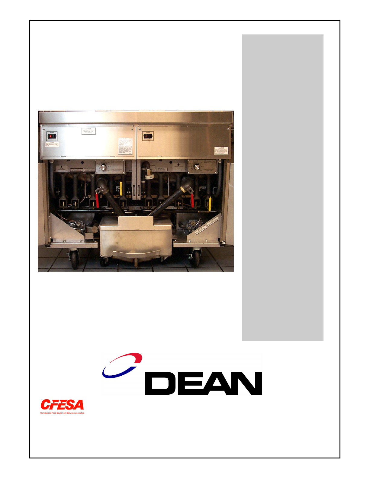
COVER PHOTO
D60G Fryer with a 75SCF Super Cascade Filter
model installed.
Page 3

SUPER CASCADE
FILTRATION SYSTEMS
INSTALLATION AND OPERATION MANUAL
TABLE OF CONTENTS
PAGE
1. PARTS ORDERING AND SERVICE INFORMATION 2
2. IMPORTANT INFORMATION 3
3. INSTALLATION 4
4. DAILY OPERATION 6
5. CLEANING AND MAINTENANCE 10
6. TROUBLESHOOTING 11
7. PARTS GUIDE 15
1. PARTS ORDERING AND SERVICE INFORMATION
1.1 ORDERING PARTS:
Customers may order parts directly from their
local Authorized Parts Distributor. For this
address and phone number, contact your
Maintenance & Repair Center or call the
factory. The factory address and phone number
are on the cover of this manual.
To speed up your order, the following
information is required:
Model Number
Type
Serial Number
With/Without Heater
Optional Equipment
Item Part Number
Quantity Needed
1.2 SERVICE INFORMATION:
Call the “800” number on the cover of this
manual for the location of your nearest
Maintenance & Repair Center or contact the
factory direct. Always give the model and serial
numbers of your filter and fryer.
To assist you more efficiently, the following
information will be needed:
Model Number
Type
Serial Number
With/Without Heater
Optional Equipment
Nature of Problem
Any other information which may be helpful in
solving your service problem
2
Page 4

2. IMPORTANT INFORMATION
CLEANING OF THE FILTER.
2.1 GENERAL: The Super Cascade Oil
Filters are units that fit inside the Dean
Industries’ Super Marathon, Decathlon,
18UE, and Flatbottom fryers.
The used oil drains by gravity from the
fryer into the filter pan and then is pumped
back to the fryer vessel.
Filtering is accomplished through two
sheets of replaceable filter paper assisted
by a micro pre-coat filter powder or by
means of a Magnum Filter Leaf Assembly.
CAUTION
THE ON-SITE SUPERVISOR IS
RESPONSIBLE FOR ENSURING THAT
OPERATORS ARE MADE AWARE OF
THE INHERENT DANGERS OF
OPERATING A HOT OIL FILTER
SYSTEM, PARTICULARLY ASPECTS OF
OIL FILTRATION, DRAINING, AND
2.2 OPERATING CONTROLS: An
“ON/OFF” switch is mounted on the fryer.
If equipped with an optional in-line heater,
a three (3) position switch
(HEAT/OFF/PUMP) is mounted on the
fryer in lieu of the “ON/OFF” switch.
This optional heater probe is offered with
the 2424-SCF System.
2.3 SAFETY FEATURES: A 5-amp
(230V) or a 7-amp (115V) circuit breaker
switches the power OFF if an overload
occurs.
factory about a unit or ordering special
parts.
2.5 PRE-INSTALLATION:
a. GENERAL: These filters, when used
in combination with a fryer, require no
additional space for filter storage.
b. STANDARDS: Installation must be
in accordance with all applicable state
and local codes.
c. ELECTRICAL CONNECTIONS:
The filter may or may not be equipped
with an in-line heater. This filter
circuit is provided with an independent
electrical supply connection on the
fryer system.
2.6 UNPACKING THE FILTER:
Loose parts include starter kit and
accessories that may have been ordered.
These are packaged inside the filter tank.
The tank top is strapped to the shipping
frame. Do not discard or misplace these,
as they will be needed.
After unpacking, immediately check the
equipment for visible signs of shipping
damage. If such damage has occurred,
contact the carrier and file the appropriate
freight claims. Do not contact the factory,
the responsibility of shipping damage is
between the carrier and the dealer or enduser.
NOTE: IF CIRCUIT BREAKER IS
TRIGGERED, DEPRESS THE RESET
BUTTON TO ACTIVATE THE
CIRCUIT AFTER THE FAILURE
HAS BEEN DETECTED AND FIXED.
2.4 RATING PLATE: Information on
this plate includes the model and serial
numbers as well as electrical requirements.
This data is essential when contacting the
3
Page 5
3. INSTALLATION:
3.1 GENERAL: On initial installation and
before each use, remove all loose parts from
the filter, wash the filter pan and all
accessories in hot, soapy water and dry
thoroughly.
1
4
2
WARNING!
DO NOT RUN WATER THROUGH
THE FILTERING SYSTEM. THE
FILTER PUMP IS NOT DESIGNED TO
HANDLE WATER. THIS WILL VOID
THE WARRANTY FOR THAT
SYSTEM, DAMAGE THE PUMP AND
CAUSE ACCIDENTS IF WATER
MIXES WITH HOT OIL.
3.2 ASSEMBLYING THE FILTER:
The Super Cascade Filter is available in two
configurations. The configurations differ in
the filtering medium used. The first
configuration uses filter paper and a holddown ring to secure that paper. The second
configuration, found on certain 2424SCFs
only, uses a Magnum Filter Leaf Kit instead
of filter paper as a filtering medium.
Filter Paper Configuration:
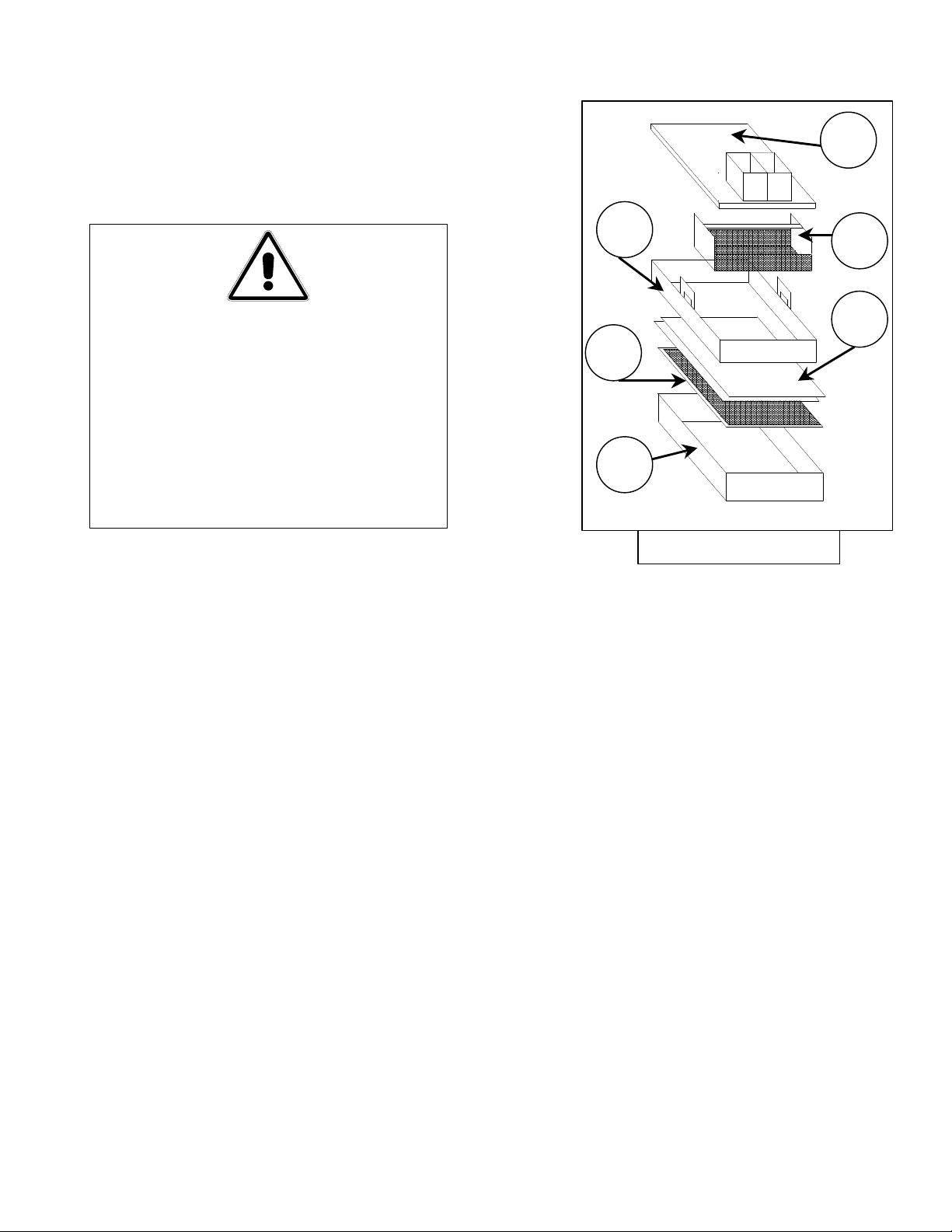
a. Figure 3-1 shows the proper assembly of
these parts:
1. Filter Pan Cover
2. Crumb Catcher Screen
3. Filter Paper (2 sheets)
4. Hold-Down Ring
5. Protective Screen/Support Grid
6. Filter Pan Assembly
3
5
6
Figure 3-1
b. First place the support grid in the bottom
of filter pan.
c. Put two filter paper sheets on top of the
support grid. Be sure the paper covers the
whole filter pan bottom.
d. Position the hold-down ring on top of the
filter papers and latch the hold-down ring
and filter papers securely against the filter
pan bottom. When positioning the holddown ring, do it evenly around the filter
pan and papers to create a good seal
around the support grid which prevents
any air from getting into the system.
e. Sprinkle 16 ounces of filter powder on the
top filter sheet. Ensure that the powder
covers the filter paper evenly.
f. Place the crumb catcher screen in the
filter pan. Allow the crumb catcher to
rest on the top edges of the hold-down
ring.
4
Page 6
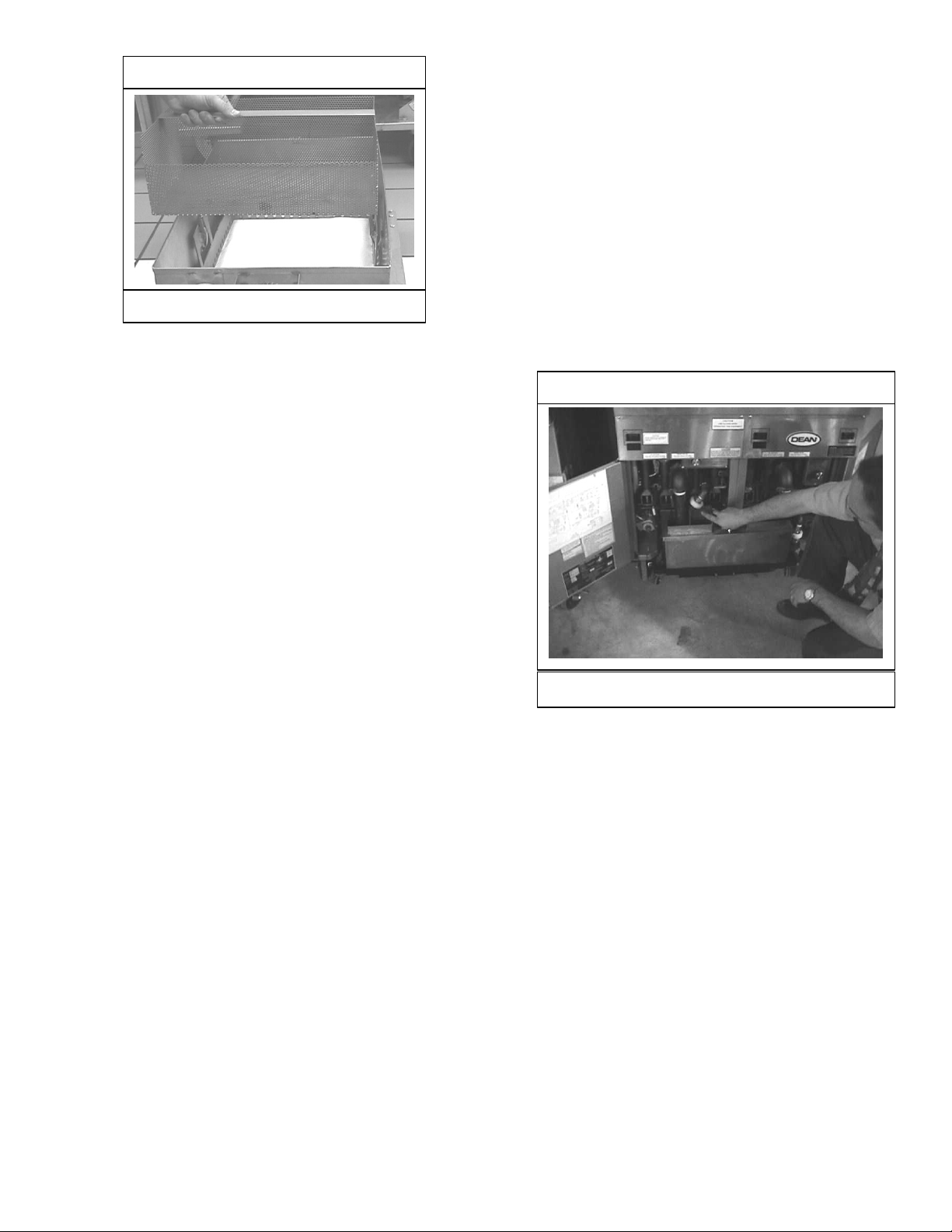
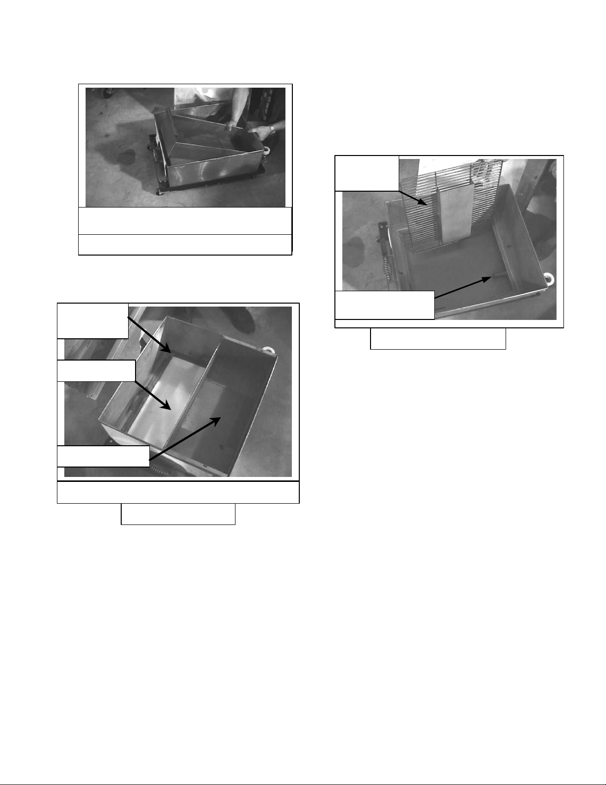
Installing crumb catcher screen.
Location of Quick Disconnects
Figure 3-2
g. Place filter pan cover onto the filter pan
assembly.
h. Roll the filter into position, either inside
the fryer for built-in operations, or
position the filter underneath the fryer
drain valve for portable operations.
i. Prior to connecting the oil return lines,
ensure the filter switch is “OFF”.
f. Connect the oil return line connector to
the fryer’s oil return line quick disconnect
coupling.
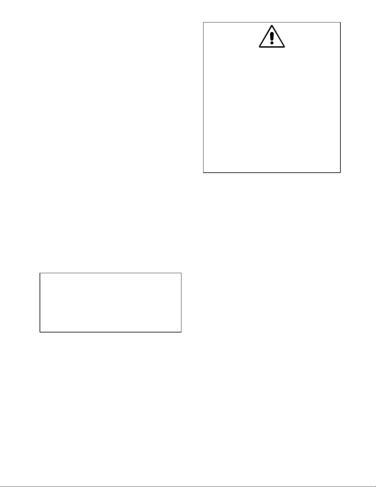
3.3 INSTALLING THE FILTER IN
THE FRYER:
a. Slide the filter inside the fryer cabinet.
b. Connect the filter’s oil return line (male
quick disconnect) into the quick
disconnect (female) in the fryer’s return
line. See figure 3-3.
j. Then connect the oil return line to the
fryer’s oil return line quick disconnect
coupling.
Magnum Filter Leaf Kit:
a. Place the Magnum Filter Leaf in the
bottom of filter pan. Ensure oil intake
pipe is aligned properly with the opening
on the filter pan lid.
b. Sprinkle Magnasol powder into oil in the
fry vessel. Do not sprinkle Magnasol
powder in the filter unit as this will clog
the oil intake in the filter pan bottom.
c. Place filter pan cover onto the filter pan
assembly.
d. Roll the filter into position inside the
fryer.
Figure 3-3
e. Before connecting the oil return lines,
ensure the filter switch is “OFF” and the
power cord is disconnected from the
power source.
5
Page 7
6
4. DAILY OPERATIONS:
Pump/Heater
Valve Handle
Removing filter unit from fryer.
Figure 4-2
Switch
Oil Return Valve
Oil Return
Polishing
Assembly
Filter Pan
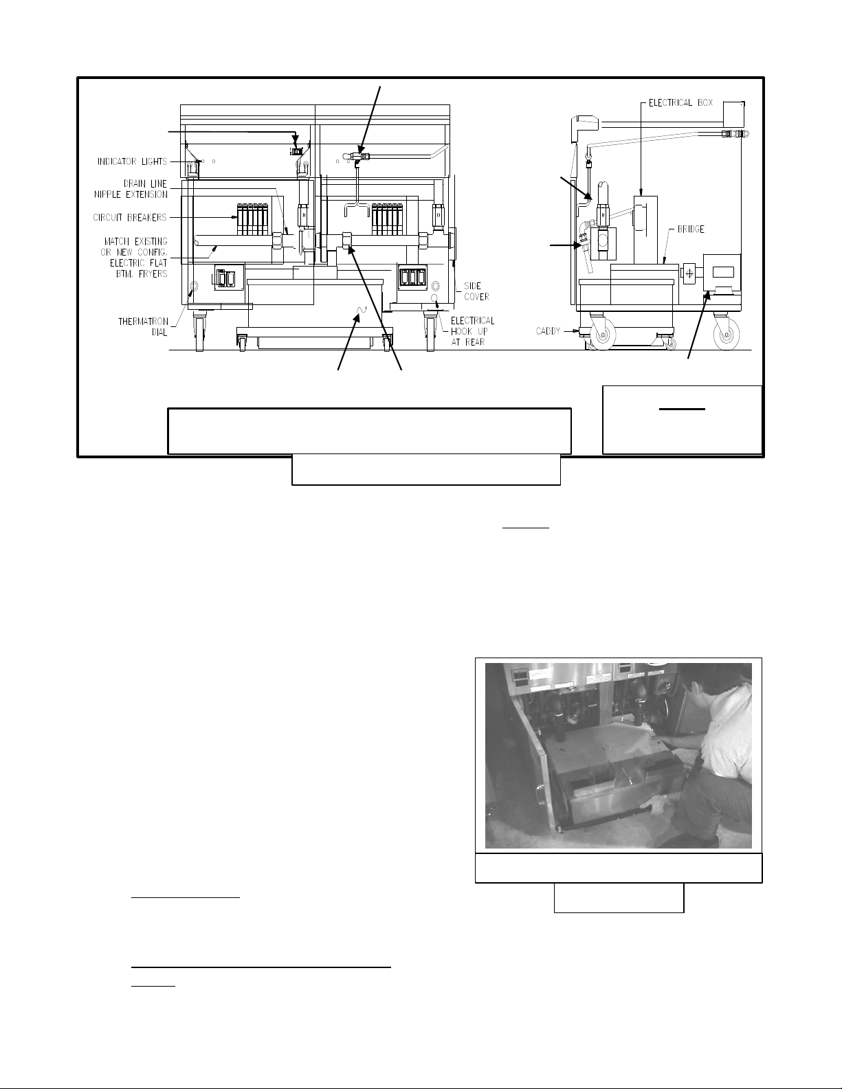
Super Cascade Installed in a 2424E Fryer System
4.1 GENERAL:
The Super Cascade Filter is designed to
operate primarily as a built-in filter unit.
Operations always start by ensuring the unit
is properly plugged in, then rolling the filter
to the fryer to be filtered. The filter will
work directly under the fryers’ drain
valves. Figure 4-1 shows the general
layout of an installed Super Cascade Filter
System with major components identified
in bold typeface. Other components,
primarily fryer components, are in standard
typeface.
Drain Valve
Pump/Motor
Legend
Major Components
Other Components
Figure 4-1
c. Gloves: Used to expedite filtering and
prevent burns from splashing oil.
4.3 FILTER PREPARATION:
a. Pull the filter unit from the fryer.
Remove the filter pan cover and crumb
screen.
4.2 FILTERING TOOLS:
These tools are not required, but are
recommended to make the filtering task
easier.
a. Measuring Cup: Used to measure
sixteen (16) ounces by volume of filter
powder.
b. One-gallon aluminum pitcher or
bucket: For dumping oil into fryer to
flush out debris.
b. Visually inspect the filter paper. Scrape
debris off the filter paper. If the filter
paper appears scuffed or darkened,
replace the filter paper per instructions
found in Section 4.4 of this manual.
Page 8
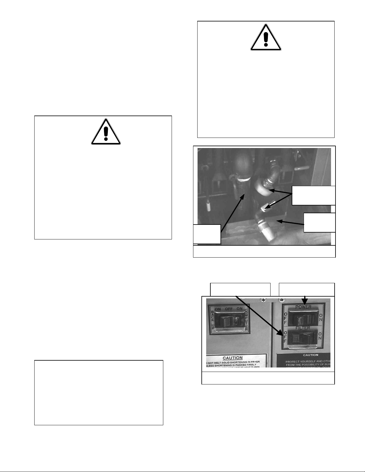
c. Sprinkle 16 ounces of filter powder on
Figure 4-3
Protection
Nipple Assembly
Figure 4-5
Filter Paper
Hold-Down
Crumb Catcher
Figure 4-4
the top filter sheet. Ensure the top filter
paper sheet is covered evenly.
Re-installing the crumb catcher.
d. Re-install the crumb catcher. Allow the
crumb catcher to rest on top of the holddown ring.
Ring
c. Roll both ends of the used (top) sheet
of paper into the center, making sure
no sediment falls out and discard.
d. Remove and check the protection
screen for cleanliness and scrub if
necessary. Ensure there is no build-up
of shortening around the nipple
assembly.
Screen
Filter assembly prior to re-installing cover.
e. Place filter pan cover on top of the filter
pan and slide the Super Cascade Filter
back into the fryer.
4.4 CHANGING FILTER PAPER:
The filter paper should be discarded when
it becomes dark or scuffed in appearance.
Follow this procedure:
a. Remove filter cover and crumb catcher
screen.
b. Open the locking clips of the hold-
down ring and lift the ring out of the
filter tank.
e. Check the filter pan for cleanliness and
scrub if necessary; check the drain
ports at the bottom rear of the filter
pan also.
f. Replace the bottom protection screen
and place a new sheet of filter paper on
top.
g. Replace the hold-down ring and
secure.
h. Replace crumb catcher and cover.
i. Go to Section 4-6, Operation, and
continue.
4.5 MAGNUM FILTER LEAF KIT:
On certain models of the 2424SCF, a
Magnum Filter Leaf kit may have been
installed in lieu of using filter paper and
the hold-down ring assembly. Install this
kit following the manufacturer’s
instructions.
a. Once the filter leaf kit has been
installed, replace the filter lid
assembly.
7
Page 9
b. Slide the filter unit under the fryers to
Figure 4-7
Quick
Disconnect
Drain
Valve
Splash
Guard
Figure 4-6
be filtered. Ensure fry vessel drains
are aligned with the openings in the
filter lid assembly.
c. Sprinkle Magnasol Powder into the
fry vessel and stir the oil. Do not
sprinkle this powder in the filter pan.
d. Go to Section 4-6, Operation, and
continue.
WARNING!
THE OIL TEMPERATURE OF THE
FRYER TO BE FILTERED SHOULD
BE AROUND 350°F (175°C). ENSURE
HOSES ARE CONNECTED
PROPERLY AND DRAIN HANDLES
ARE IN PROPER POSITIONS PRIOR
TO OPERATING ANY SWITCHES
OR VALVES. FAILURE TO DO THIS
CAN RESULT IN SEVERE BURNS.
WARNING!
DO NOT RUN WATER THROUGH THE
FILTERING SYSTEM. THE FILTER
PUMP IS NOT DESIGNED TO
HANDLE WATER. THIS WILL VOID
THE WARRANTY FOR THAT
SYSTEM, DAMAGE THE PUMP AND
CAUSE ACCIDENTS IF WATER
4.6 OPERATION:
Figure 4-1 shows a Super Cascade Filter
installed and ready for operation. When
filtering, follow these steps:
a. Disconnect filter from fryer. Follow
the appropriate Sections 4.3 and 4.4,
or Section 4.5 to prepare your filter for
operation.
b. Then connect the filter return line
connector into the quick disconnect in
the fryer return line.
CAUTION
BEFORE TURNING FILTER SWITCH
“ON” OR TO HEATER POSITION,
ENSURE QUICK DISCONNECTS ARE
CONNECTED PROPERLY OR
SERIOUS INJURY MAY OCCUR.
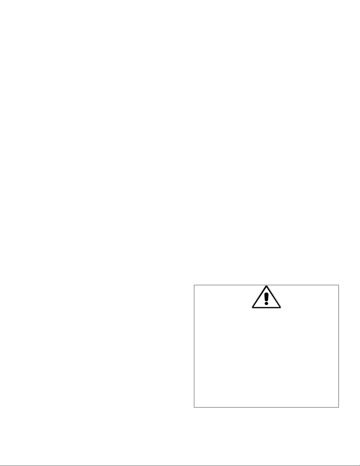
c. Next turn the fryer main power switch
to the “OFF” position.
Fryer Power SwitchFilter Power Switch
d. 2424SCF (Only): If equipped with a
optional heater, before filtering, turn
the filter switch to the heater “HTR”
position for a few minutes in order to
melt the solid shortening in the pump
8
Page 10
lines. Then turn the power switch on
the fryer to the “OFF” position.
e. Open the fryer door and be sure that
the filter is in the proper position
under the fryer drain valve.
f. To open the drain valve, pull the
handle out and allow all the oil in the
fryer to drain into the filter pan.
g. Turn filter switch “ON” to begin
pumping clean oil into the fryer.
Allow the oil to flow for a few seconds
to wash out sediment on the bottom of
the cooking vessel before closing the
drain valve.
h. Push on the drain valve handle to
close. It takes approximately 5 to 7
minutes for the filter to pump all the
oil back into the fryer.
i. Turn filter switch on the fryer to the
“OFF” position after all the oil has
been pumped back into the fryer.
Allow the pump to run for 10 – 13
seconds after air bubbles appear in the
fryer vessel before shutting off to clear
shortening/oil from the return lines.
WARNINGS!
DO NOT LEAVE A FILTER
MACHINE UNATTENDED DURING
OPERATION. THE ACTION OF THE
OIL MOVING THROUGH THE
LINES COULD CAUSE A FLEXIBLE
RETURN HOSE TO POP LOOSE
AND LEAK HOT OIL.
AVOID SERIOUS SPILLING OF HOT
OIL ONTO THE FLOOR. DRAIN
ONLY THE AMOUNT OF OIL
INDICATED ON THE FILTER PAN.
CAUTION
OPERATING THE BURNERS WITHOUT
OIL IN THE FRYER VESSEL WILL
CAUSE DAMAGE TO THE FRYER AND
VOID THE WARRANTY.
NOTE: AFTER FILTERING IT MAY
BE NECESSARY TO SCRAPE OFF ALL
OF THE DEBRIS ACCUMULATED ON
TOP OF THE FILTER PAPER AND
DISCARD.
9
Page 11
5. CLEANING & MAINTENACE
5.1 GENERAL:
Cleaning operations fall into three general
categories:
a. The continuing habit of clean-up every
time the filter unit is used;
b. The daily clean-up at the close of each
business day;
c. And, a more thorough weekly cleaning.
5.2 EACH FILTER USE:
Every time your Super Cascade Filter
System is used:
a. Wash down the sides of the filter pan
with hot oil.
b. Scrape and possibly change the top
sheet of filter paper. Always scrape
sediment and debris from the paper
when the system is warm; this prolongs
the life of the paper.
c. Wipe up any oil which may have
splashed or spilled.
d. Wipe all exterior surfaces of the filter
unit.
5.3 DAILY-CLOSE OF BUSINESS:
One of the last orders of business at the
close of a working day should be to filter
the oil in all fryers. When the last fryer is
finished, follow these steps:
a. Run the filter pump for an additional
10 – 15 seconds after air bubbles start
coming from the oil return line. This
should clear the filter lines of any
remaining oil or shortening.
b. Remove the filter unit from the fryer.
Scrape the top piece of filter paper.
Replace filter paper if it is scuffed or
dark.
c. Remove the filter pan cover, the
crumb catcher, and hold-down ring
assembly; then take out the paper and
protection screen.
d. Wash all of removed items with soapy
water.
e. Clean the filter pan with a dry towel.
f. Be sure that all items have been dried
thoroughly before reassembling.
5.4 WEEKLY:
Follow the same procedure as for
“DAILY”, with these additional steps:
a. Check the connections of the inlet
lines. Tighten if the inlet lines become
loose or start to leak oil.
b. Wash the filter pan with hot, soapy
water and a brush. Dry and
reassemble with new filter paper.
c. Clean thoroughly under, around, and
behind the fryers and filtering area.
d. Avoid getting water inside the
motor/pump housing when washing
the filter pan.
WARNING!
DO NOT RUN WATER THROUGH THE
FILTERING SYSTEM AS PART OF THE
CLEANING PROCESS. THE FILTER
PUMP IS NOT DESIGNED TO HANDLE
WATER. THIS WILL VOID THE
WARRANTY FOR THAT SYSTEM,
HASTEN PUMP FAILURE AND CAUSE
ACCIDENTS IF WATER MIXES WITH
HOT OIL.
10
Page 12
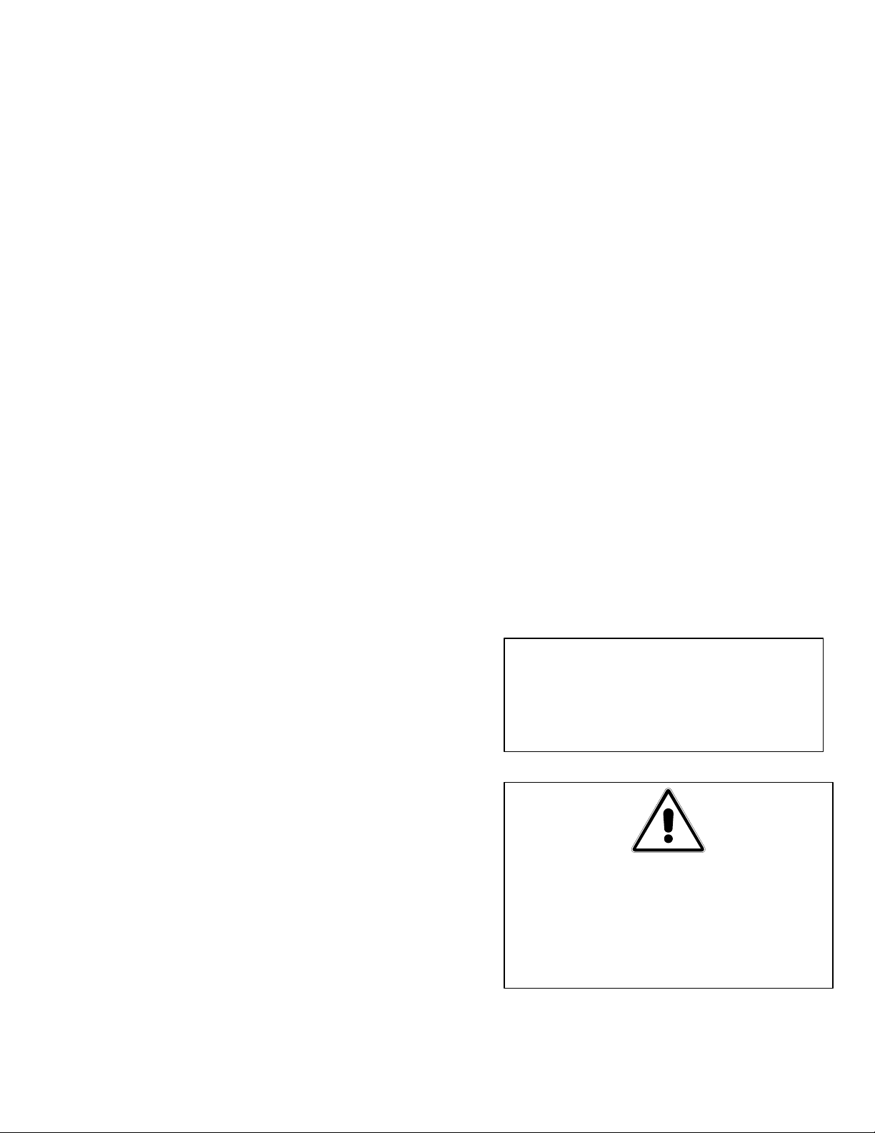
6. TROUBLESHOOTING GUIDE
6.1 OPERATING PROBLEMS:
Plugged lines and plugged filter paper
account for over 90% of malfunctions. The
troubleshooting flowcharts found later in this
chapter can provide a step-by-step guide to
correct these and other common
malfunctions.
a. PLUGGED LINES:
1. If you are using solid shortening and
the filter is operated improperly, the
motor may shut off before the hot oil is
completely pumped back into the fryer
and solidification of the oil in the lines
could occur as the oil cools.
b. PLUGGED PAPER: Improper use of the
filter pre-coat powder will cause a slow oil
flow return rate. The filter paper should at
least be scraped (if not discarded) after
filtering a particularly dirty fryer. First
indication of paper plugging is a surging,
jerking movement of the hose. To correct,
check the instructions for the right use of
powders and scrape the filter paper more
frequently. Also review procedures found
in Chapter 6, Troubleshooting Guide.
6.2 TROUBLESHOOTING GUIDES:
These troubleshooting procedures help locate
the most encountered problems and will give
possible solutions/corrective action to be
taken.
2. Oil drains from the fryer vessel into the
filter pan, then it is drawn through the
filter paper, exits the pan through the
ports on the filter pan bottom, then
flows through a rigid tube to the filter
pump. From the pump, oil returns to
the fryer through the flexible oil return
hose or the internally-plumbed oil
return line in the fryer.
3. A solid shortening plug can exist
anywhere in this path; locate the plug
using the procedures found in Chapter
6, Troubleshooting Guide.
4. To guard against plugged lines when
using solid shortening, follow these
guidelines:
a. Also, at the end of the filtering
cycle, let the filter flow bubbles
into the fryer through the flexible
hose for about ten seconds. If it is
blowing bubbles, air is moving
through the lines and they cannot
be plugged.
b. When filtering is completed,
always disconnect the flexible line
and hang it up to drain.
To use these flowcharts, start at the top of
the diagram. Follow each step in sequence.
If the answer to a question is “yes”, proceed
downward to the next step.
If the answer is “no”, follow the arrow to the
right and follow the next step. Arrows direct
the troubleshooter through the sequence.
DANGER!
USE EXTREME CARE DURING
ELECTRICAL CIRCUIT TESTS. LIVE
CIRCUIT WILL BE EXPOSED.
WARNING!
INSPECTION, TESTING, AND REPAIR
OF GAS OR ELECTRICAL EQUIPMENT
SHOULD BE PERFORMED BY
QUALIFIED PERSONNEL.
11
Page 13
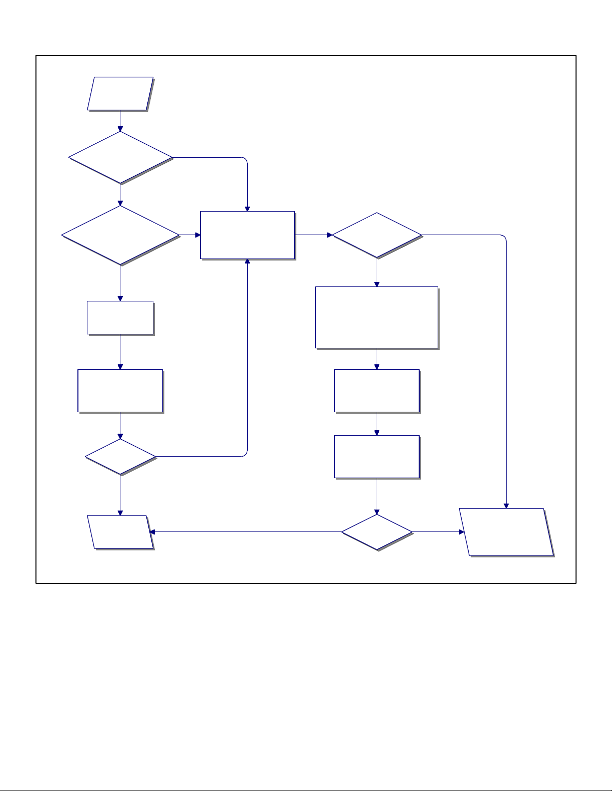
6.3 FILTER PUMP FAILS TO PUMP OIL?
Filter Pump
fails to pump
oil.
Is this a
2424SCF Fryer/Filter
System?
Yes
Is a Dean Heater
Retrofit Kit #44760-1SK
installed?
Yes
Turn heater "ON"
and run heater for
15 minutes.
Then insert flexible oil
return hose into the filter
pan holster. Turn pump
motor "ON".
No
Disconnect flexible oil
return hose. Make sure it
No
is cool before handling.
Try blowing air through it.
Can you blow
air through it?
Yes
No
Submerge hose into hot water (over
120 degrees F). Keep both ends
out of the water. If water gets into
the hose, the water will cause
severe splattering when hose is
reconnected to the filter.
Once shortening has
softened, reconnect the
flexible oil return hose
to the filter.
Does oil flow?
Yes
Conduct normal
filter operations.
No
Insert flexible oil return
hose into the filter pan
holster. Turn pump
motor "ON".
Yes No
Does oil flow?
Blockage is between
the bottom of the filter
pan and the flex hose
valve. Go to page 14.
12
Page 14
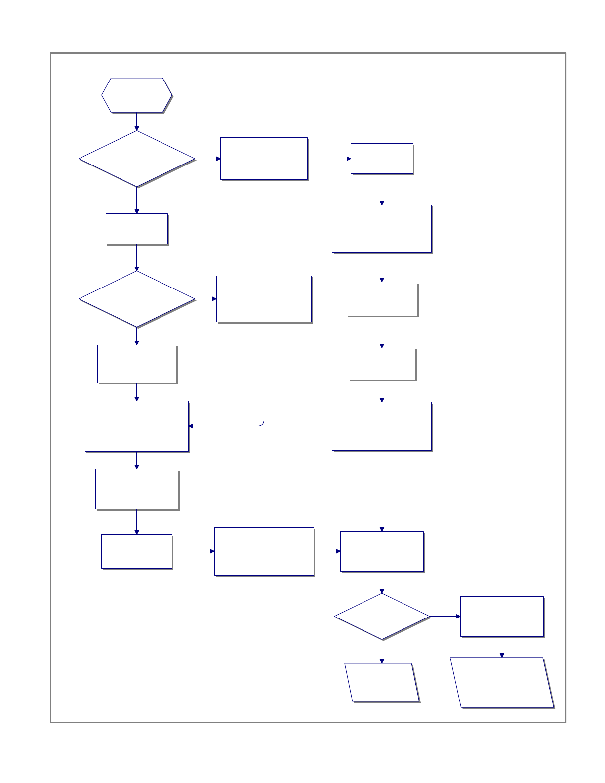
6.4 RATE OF OIL RETURN TO FRYER SLOWS?
Rate of oil
return to the fryer
is slowing.
Is this the
first fryer to be filtered
during this filtering
session?
Yes
Check the filter
paper in the filter
pan.
Is the filter
paper properly secured
by the hold down
ring?
Yes
Paper may be
plugged by improper
use of precoat/slurry.
Change the filter paper.
Throw away the old top
sheet and use the old
bottom sheet as the new top
sheet.
Check the filter sump.
No
No
Sediment collects
around the suction pipe
in the filter bottom.
Paper may not be
secured by the hold down
ring. Air is being allowed
to get into the system.
Remove the filter
pan cover.
Unlatch hold-down ring and
remove the filter paper and
filter paper support grid.
Clean support grid
and set aside
temporarily.
Wipe sediments
out of the bottom
of the filter pan.
Inspect drain ports at the
bottom rear of the filter pan
and remove any sediment
or visible blockages.
Take a new sheet and
place it in the bottom
of the pan. Place the
new top sheet over it.
Secure the filter
papers by latching
the hold down ring.
Pour slurry over new filter
papers.
13
Reassemble the filter
pan assembly. Turn
the pump motor "ON".
Has
the oil return rate
improved?
Yes
Conduct normal
filter operations.
Blockage may be
No
between the filter pan
bottom and the flex
hose valve.
Go to flowchart titled
"Blockage between
Filter Pan and Flex Hose
Valve" on page 14.
Page 15
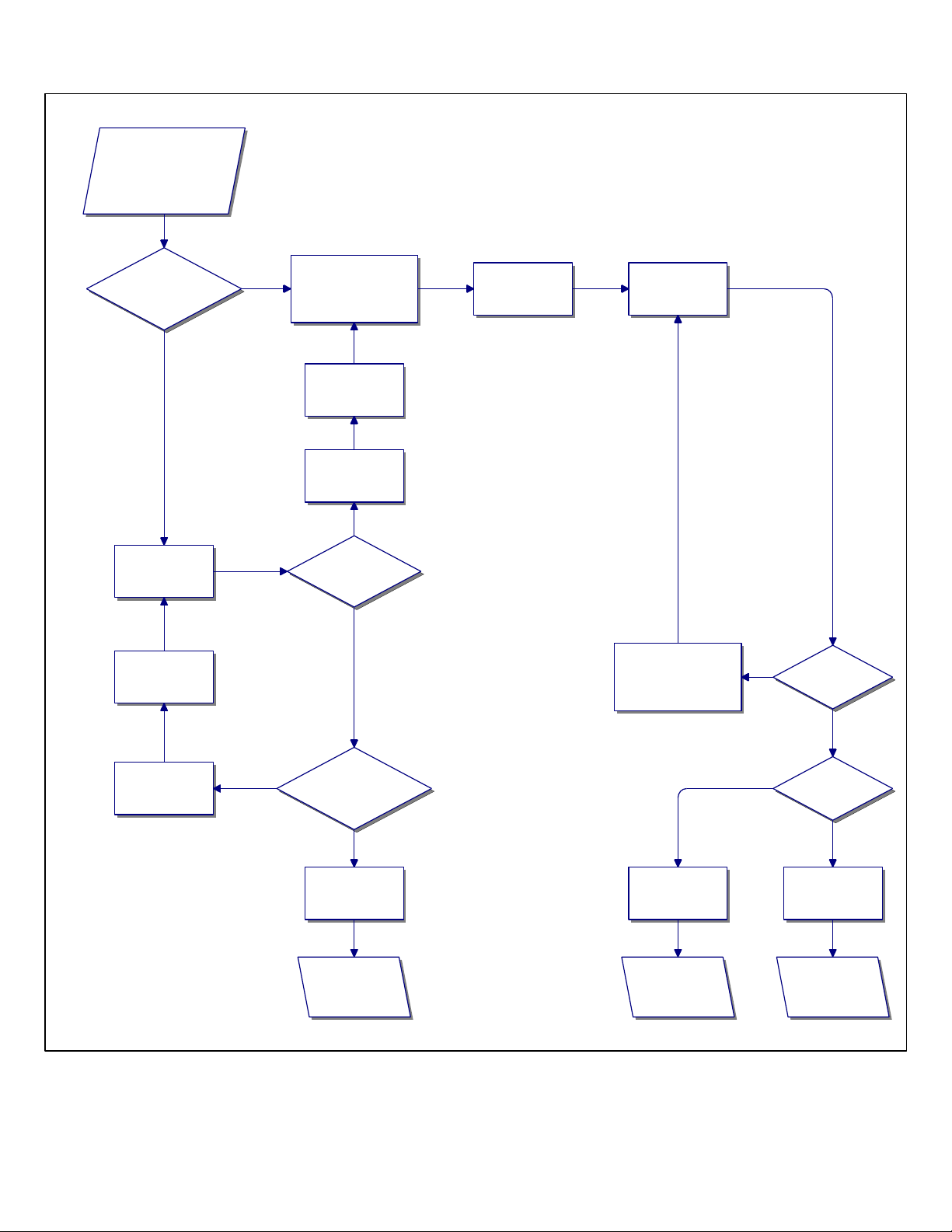
6.5 BLOCKAGE BETWEEN FILTER PAN AND FLEX HOSE VALVE?
Blockage has been
determined to be between
the filter pan bottom and
the flex hose valve.
Is this a
2424SCF Fryer/Filter
System?
Yes
Turn the heater
"ON".
Reconnect the
power cord to the
proper outlet.
Disconnect oil line from
No
the filter pan to the
pump at the pump end.
working properly.
Turn the heater
"OFF".
The heater is
Yes
Does the
suction line feel
warm?
No
Put finger over the
inlet connection to
the pump.
Turn the pump
"ON".
Check filter circuit
breaker. Push the
circuit breaker reset
button.
No
Does
the pump motor
run?
Yes
Turn the heater
switch "OFF".
No
Is the power
cord connected to
the outlet?
Yes
Heater is faulty.
Contact your local
Factory Authorized
Service Center!
14
Pump is clear of
any blockages.
Go to page 11 and
continue following
the flowchart.
Yes
Pump motor is
clogged or faulty.
Contact your local
Factory Authorized
Service Center.
Do you feel
suction?
No
Page 16
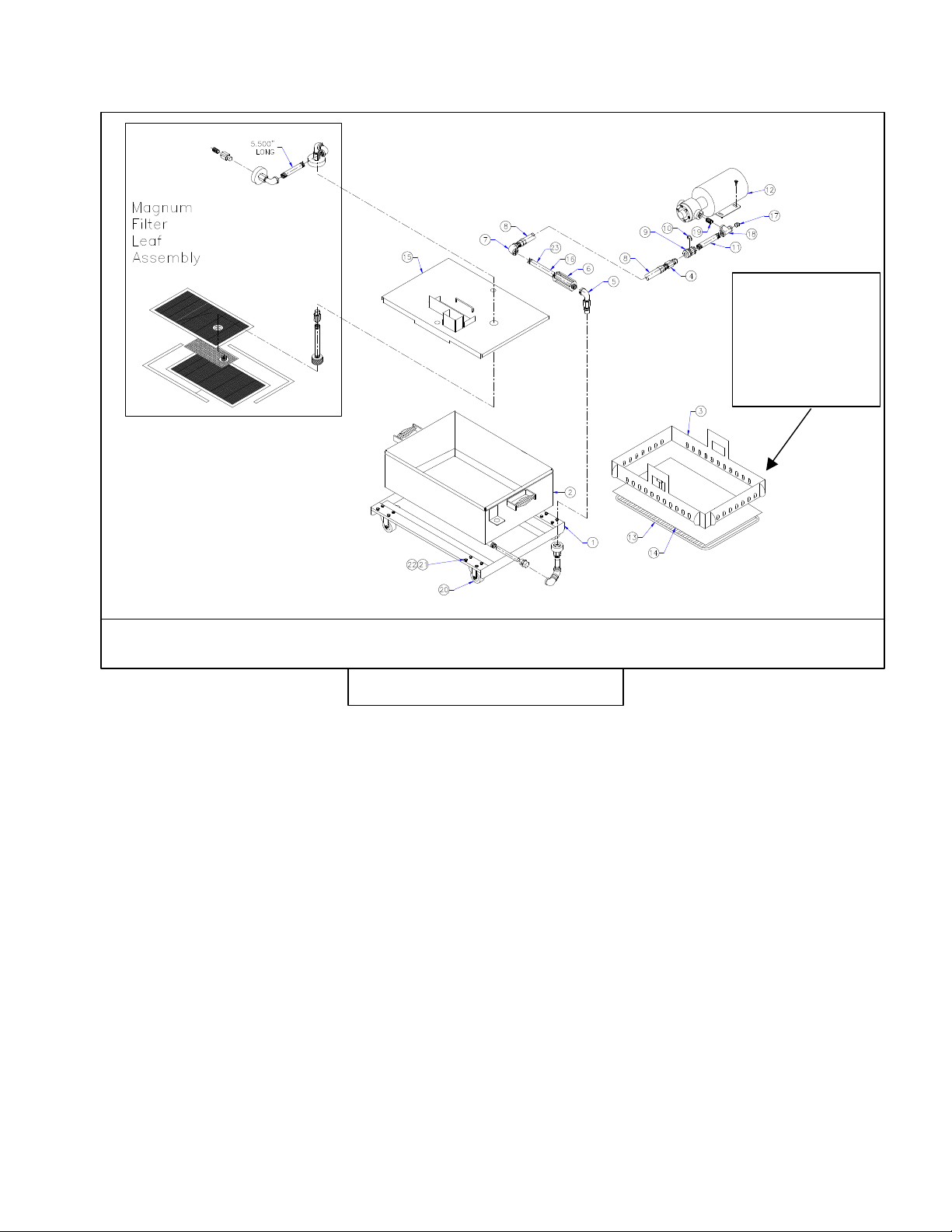
7. PARTS GUIDE FOR THE SUPER CASCADE FILTER SYSTEM
Used with all
SCFs except
2424-SCF
w/Magnum
Filter Leaf
Exploded Diagram of a Super Cascade Filter
Figure 7-1
Use the above drawing, Exploded Diagram of a Super Cascade Filter, to identify parts found on your
Super Cascade Filter System. Item numbers listed in the parts lists correspond to items numbered in
the above drawing. Not every part is listed or shown on the drawing or in the parts lists. Some Super
Cascade Filter configurations may not use all of the parts shown in the drawing. Both filter medium
configurations are shown above – Filter Paper and Magnum Filter Leaf assemblies. The Magnum
Filter Leaf system is used in certain models of the 2424-SCF only. All other Super Cascade Filter
systems use filter paper as a filtering medium. A parts list for the Heater Retrofit Kit # 44760-1SK is
included at the end of this chapter. An exploded drawing and associated parts list for the Magnum
Filter Leaf Kit is provided on page 18. Both the 44760-1SK and the 2668 are options used with the
2424-SCF only.
15
Page 17
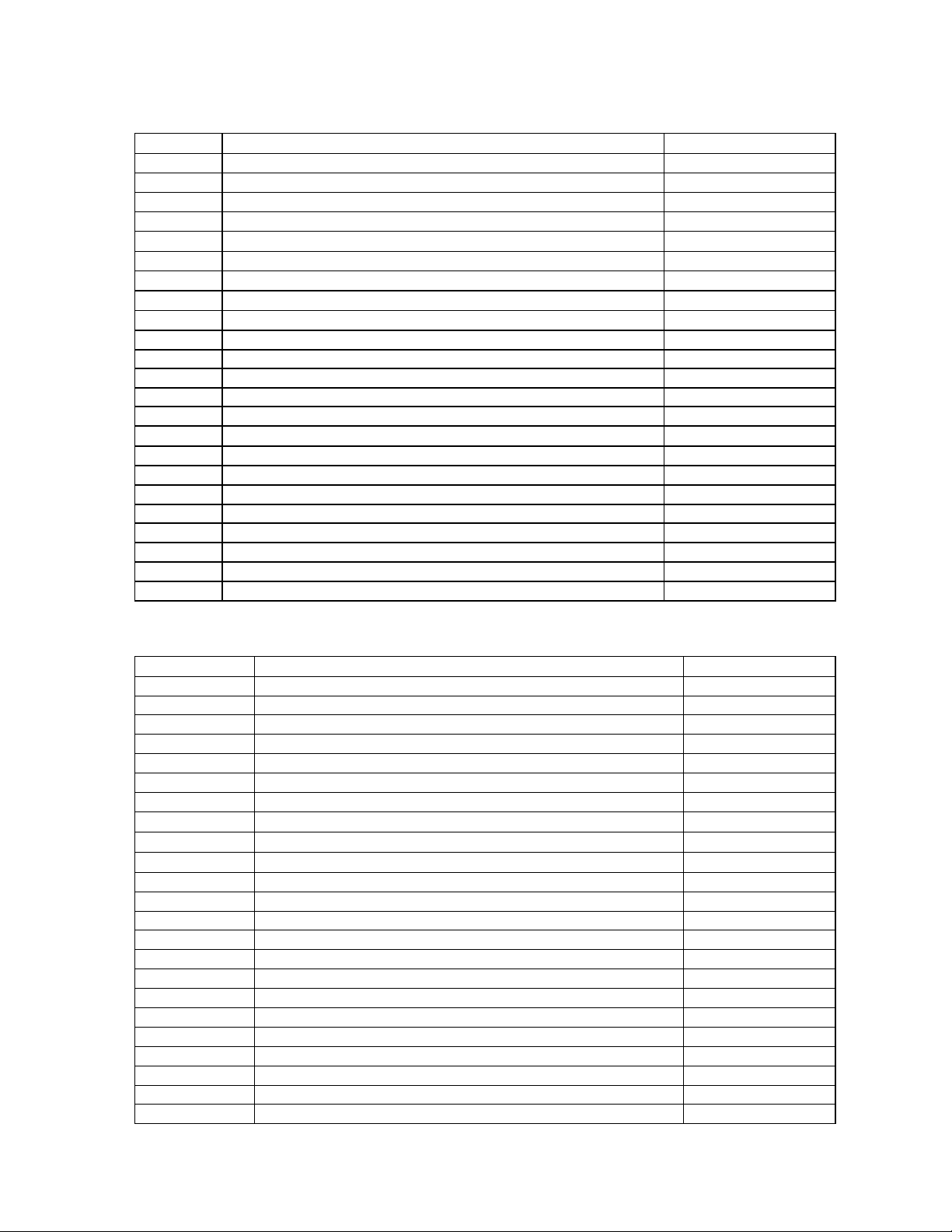
Super Cascade Filter Assembly, 2424-SCF, #5540
9
Item No. Description Part Number
1
2
3
4
5
6
7
8
9
10
11
12
13
14
15
16
17
18
19
20
21
22
23
Filter Pan Caddy Assembly, 2424SCF 55408
Filter Pan with Fittings, 2424SCF 55407
Hold Down Ring Assembly (LJS) 55378
Quick Disconnect, Male, 1/2" 1644
Elbow, Street, 1/2"x90° 1687
Oil Return Handle Assembly 44681
Elbow, Black Iron, 1/2"x90° 1013
Hose Assembly, Pump Line (LJS) 44764
Quick Disconnect, Female, 1/2" 1645
Snap Ring 1969
Nipple, 1/2"x7-1/4"TBE 1062
Pump/Motor Combo, 8D, 120V 1742
Grid & Channel Assembly - Jumbo 55121
Filter Paper, 16 3/8"x24 3/8" 1054
Lid Assembly, 2424SCF 55410
Nipple, 1/2"x8, Black 1056
Plug, Pipe, 3/8-18 NPT SQ HD 1674
Tee, 1/2"x3/8"x1/2", Black 1765
Nipple, 1/2"x2, Black 1060
Caster, 2" Filter Pan 1003
Bolt, 1/4-20x1/2 HX HD ZP GR5 1004
Nut, Nylock, 1/4-20 1005
Hose Assembly w/Fittings 44764
Super Cascade Filter Assembly # 55395
Item No. Description Part Number
Not Shown Filter, Crumb Basket Ass embly 44790
Not Shown SCF L Drain Extension, 1.25"x8.75" 44-1110
Not Shown Drain Extens io n (1.5"x9.75') SCF 44-1111
1
2
3
4
5
6
7
8
9
10
11
12
13
15
16
19
20
21
22
23
Filter Pan Caddy Assembly, 100# (94) 55389
Filter Pan Assembly with Fittings 55386
Hold Down Ring Assembly 55372
Quick Disconnect, Male, 1/2" 1644
Elbow, Street, 1/2"x90°, Chrome Plated 1687SC
Oil Return Handle Assembly 44681
Elbow, 1/2"x90°, Black, Chrome Plated 1011SC
Filter Hose Assembly 44790
Quick Disconnect, Female, 1/2" 1645
Snap Ring 1969
Nipple, Black, 1/2"x 5 TBE, Chrome Plated 1047SC
Pump/Motor Combo, 5D 1726
Screen Assembly 55370
Lid Assembly for 100# Super Cascade Filter 55387
Nipple, 1/2x5, Black 1074
Nipple, 1/2"x2-1/2", Black 2009
Caster, 2" Filter Pan 1003
Bolt, 1/4-20x1/2" HX HD ZP GR5 1004
Nut, Nylock 1/2-20 1005
Hose Assembly w/Fittings 55304
Page 18
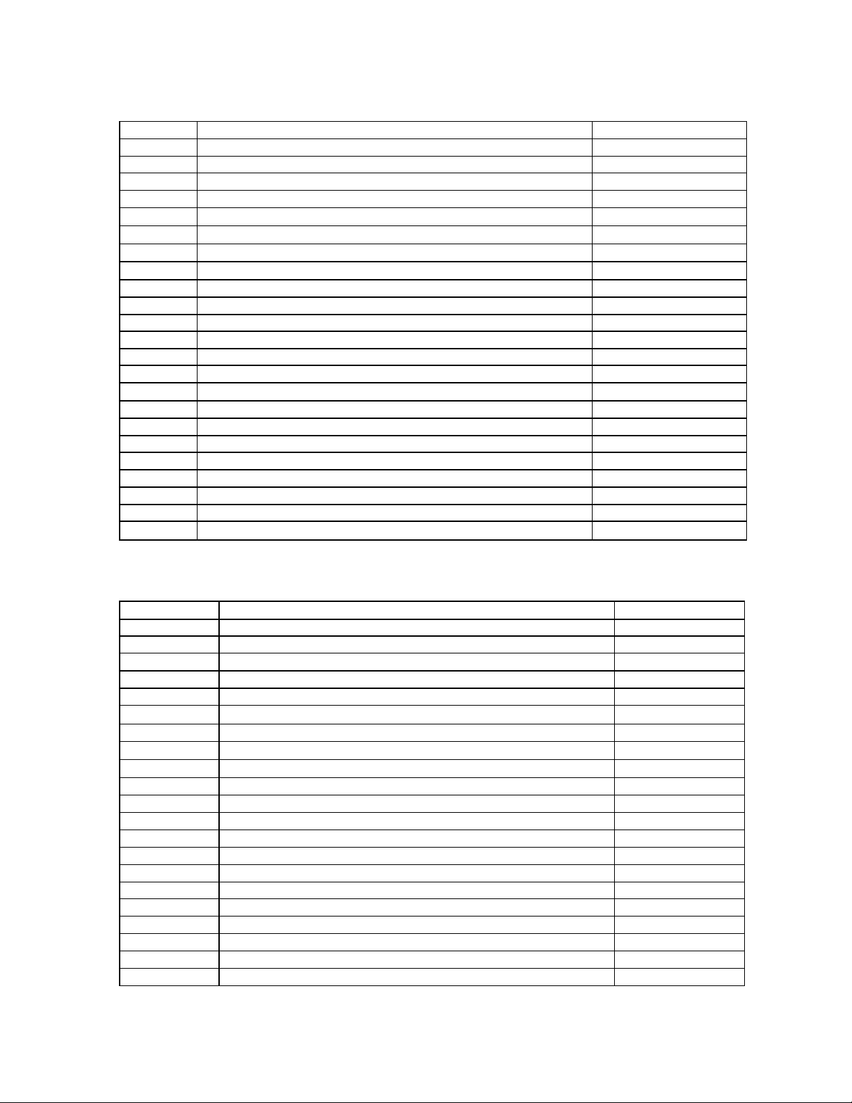
Super Cascade Filter Assembly, 85-SCF, #55440
y
Item No. Description Part Number
1
2
3
4
5
6
7
8
9
10
11
12
13
14
15
16
17
18
19
20
21
22
23
Filter Pan Caddy Assembly, 2424SCF 55408
Filter Pan with Fittings, 2424SCF 55407
Hold Down Ring Assembly (LJS) 55378
Quick Disconnect, Male, Vz 1644
Elbow, Street, 90°, 1/2", Chrome Plated 1687SC
Oil Return Handle Assembly 44681
Elbow, Black Iron, 1/2"x90° 1011
Hose Assembly, Pump Line (LJS) 44764
Quick Disconnect, Female, 1/2" 1645
Snap Ring 1969
Nipple, 1/2"x7-1/4"TBE 1062
Pump/Motor Combo, 5D, 120V 1726
Grid & Channel Assembly - Jumbo 55121
Filter Paper, 16 3/8"x24 3/8" 1054
Lid Assembly, 2424SCF 55410
Nipple, 1/2"x8, Black 1056
Plug, Pipe, 3/8-18 NPT SQ HD 1674
Tee, 1/2"x3/8"x1/2", Black 1765
Nipple, 1/2"x2, Black 1060
Caster, 2" Filter Pan 1003
Bolt, 1/4-20x1/2 HX HD ZP GR5 1004
Nut, Nylock, 1/4-20 1005
Hose Assembly w/Fittings 44764
Super Cascade Filter Assembly, 18UE-SCF, #55455
Item No.
Not Shown Filter, Crumb Basket Assembl
1
2
3
4
5
6
7
7
8
9
11
13
14
15
16
19
20
21
22
23
Description
Filter Pan Caddy Assembly, 100# (94) 55389
Filter Pan Assembly, 18UE-SCF 55454
Hold Down Ring Assembly 55372
Quick Disconnect, Male, 1/2" 1644
Elbow, Street, 1/2"x90°, Chrome Plated 1687SC
Oil Return Handle Assembly 44681
Elbow, Black Iron, 1/2"x90° 1011
Elbow, 1/2"x90°, Black, Chrome Plated 1011SC
Filter Hose Assembly 55388
Quick Disconnect, Female, 1/2" 1645
Nipple, Black, 1/2"x5 TBE, Chrome Plated 1047SC
Pan Bottom Protective Screen Assembly 55370
Filter Paper, 16 3/8"x 24 3/8" 1054
Lid Filter Pan Assembly, 18UESCF 55449
Nipple, 1/2x5, Black 1074
Nipple, 1/2"x2-1/2", Black 2009
Caster, 2" Filter Pan 1003
Bolt, 1/4-20x1/2" HX HD ZP GR5 1004
Nut, Nylock 1/2-20 1005
Hose Assembly w/Fittings (20.625") 55304
Part Number
44790
Page 19
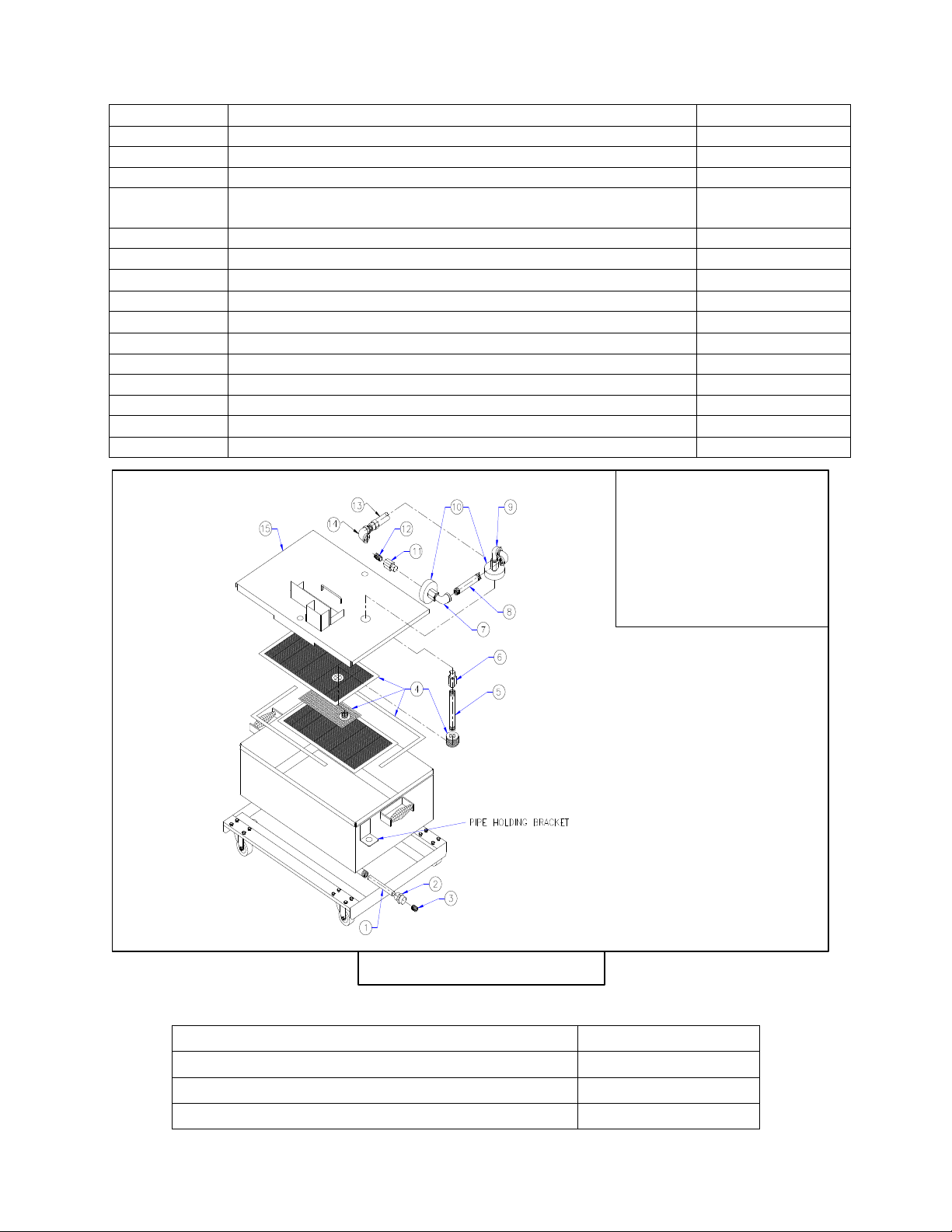
Magnum Filter Leaf Assembly, 2424-SCF(use Figure 7-2)
Figure 7-2
Item No. Description Part Number
1 Plug ½” CRS RD Bar x 4-7/8” 55-0608
2 Coupling ½” NPT Hex 2667
3 Pipe Plug ½” NPT Allen Head 2583
4 Magnum Filter Leaf Kit w/Compression Cap (Large)
(includes screens, seal frames, grid, and compression cap)
5 Nipple 3/8” x 10-3/8” S.STL (10-3/8”) 2664SS
6 Coupler Nipple 3/8” NPT 1414
7
8 Nipple 3/8” x 5-1/2” S.STL 2164SS
9
10 Coupler Assembly, 3/8” NPT 55016
11 Coupler Nipple 3/8” NPT 1414
12 Nipple 3/8” x Close S.STL (1.0”) 1014SS
13 Hose Assembly (LJS Pump) (8.5”) 44764
14
15 Lid Assembly for 100# 55410
Elbow, Street 3/8” x 90° S.STL
Elbow, Street 3/8” x 90° S.STL
Elbow, ½” x 3/8” x 90°
Magnum Filter Leaf
Assembly with
Associated
Components of a
2424-SCF
2668
2007SS
2007SS
1013
LJS Heater Retrofit Kit (2424-SCF-94)
Complete kit: 2424SCF Heater Retrofit Kit 44760-1SK
Heater Probe Assembly 55305
Probe Heater 1957
Fuse 2A Slow Blow 1131
18
Page 20

Dean , 8700 Line Avenue, Shreveport, Louisiana 71135
TEL 1-318-865-1711 FAX (Parts) 1-318-219-7140 (Tech Support) 1-318-219-7135
PRINTED IN THE UNITED STATES
SERVICE HOTLINE
1-800-551-8633
Price: $6.00
819-5658 10-98
 Loading...