

Deam Edan M8, M8 User manual


About this Manual
Imported by:
DEAM S.R.L, 30 – 64222464 - 2
Av. Maipú 380 – Local 1, Córdoba,
X5000IBH - Argentina.
Technical Director: Bioengineer Juan Pablo Giulioni, Mat: 5348 – 28676206
Autorizado por A.N.M.A.T
PM- 1317 - 17
Condition of sale: exclusive professional and Health Institutions
P/N: .54.100231-19
Release Date: September 2010
© Copyright EDAN INSTRUMENTS, INC. 2007-2010. All rights reserved.

Statement
This manual will help you understand the operation and maintenance of the product better. It is
reminded that the product shall be used strictly complying with this manual. User’s operation
failing to comply with this manual may result in malfunction or accident for which EDAN
INSTRUMENTS, INC. (hereinafter called EDAN) can not be held liable.
EDAN owns the copyrights of this manual. Without prior written consent of EDAN, any
materials contained in this manual shall not be photocopied, reproduced or translated into other
languages.
Materials protected by the copyright law, including but not limited to confidential information
such as technical information and patent information are contained in this manual, the user shall
not disclose such information to any irrelevant third party.
The user shall understand that nothing in this manual grants him, expressly or implicitly, any
right or license to use any of the intellectual properties of EDAN.
EDAN holds the rights to modify, update, and ultimately explain this manual.
Responsibility of the Manufacturer
EDAN only considers itself responsible for any effect on safety, reliability and performance of
the equipment if:
Assembly operations, extensions, re-adjustments, modifications or repairs are carried out by
persons authorized by EDAN, and
The electrical installation of the relevant room complies with national standards, and
The instrument is used in accordance with the instructions for use.
Upon request, EDAN may provide, with compensation, necessary circuit diagrams, and other
information to help qualified technician to maintain and repair some parts, which EDAN may
define as user serviceable.

1
Terms Used in this Manual
This guide is designed to give key concepts on safety precautions.
WARNING
A WARNING label advises against certain actions or situations that could result in personal
injury or death.
CAUTION
A CAUTION label advises against actions or situations that could damage equipment, produce
inaccurate data, or invalidate a procedure.
NOTE
A NOTE provides useful information regarding a function or a procedure

Table of Contents
Chapter 1 Intended Use and Safety Guidance ................................................................................1
1.1 Intended Use...........................................................................................................................1
1.2 Safety Guidance.....................................................................................................................1
1.2.1 Environment................................................................................................................1
1.2.2 Power Source Requirements.......................................................................................1
1.2.3 Grounding the Monitor ...............................................................................................1
1.2.4 Equipotential Grounding.............................................................................................2
1.2.5 Condensation...............................................................................................................2
1.2.6 Safety Precautions.......................................................................................................2
1.2.7 Explanation of Symbols on the Monitor.....................................................................5
Chapter 2 Installation of Monitor ....................................................................................................7
2.1 Opening the Package and Checking.......................................................................................7
2.2 Installing Wall Mount for the Monitor (Optional).................................................................7
2.3 Connecting the Power Cable..................................................................................................8
2.4 Powering on the Monitor .......................................................................................................9
2.5 Connecting Patient Sensors....................................................................................................9
2.6 Checking the Recorder...........................................................................................................9
Chapter 3 Introduction....................................................................................................................10
3.1 General Information.............................................................................................................10
3.2 Screen Display .....................................................................................................................15
3.3 Button Functions..................................................................................................................19
3.4 Interfaces..............................................................................................................................21
3.5 Built-in Rechargeable Battery..............................................................................................24
Chapter 4 System Menu..................................................................................................................25
4.1 Patient Setup.........................................................................................................................26
4.2 Default Setup........................................................................................................................27
4.3 Mark Event...........................................................................................................................28
4.4 Face Select ...........................................................................................................................29
4.5 Time Setup ...........................................................................................................................30
4.6 Record Setup........................................................................................................................31
4.7 Module Setup.......................................................................................................................33
4.8 Tracing Waveforms Selection ..............................................................................................33
4.9 Monitor Version ...................................................................................................................34
4.10 Alarm Volume ....................................................................................................................34

1
4.11 Key Volume........................................................................................................................35
4.12 Drug Calculation................................................................................................................35
4.13 Waveform Demonstration..................................................................................................36
4.14 Maintenance.......................................................................................................................36
4.15 Data Storing .......................................................................................................................40
Chapter 5 Face Select.......................................................................................................................45
5.1 Selecting Operating Screen..................................................................................................45
5.2 Standard Screen....................................................................................................................45
5.3 Trend Screen.........................................................................................................................46
5.4 oxyCRG Screen....................................................................................................................48
5.5 Large Font Screen................................................................................................................49
Chapter 6Alarm...............................................................................................................................53
6.1 Alarm Modes........................................................................................................................53
6.1.1 Alarm Level...............................................................................................................53
6.1.2 Alarm Modes.............................................................................................................53
6.1.3 Alarm Setup...............................................................................................................55
6.2 Alarm Cause.........................................................................................................................57
6.3 Silence..................................................................................................................................58
6.4 Parameter Alarm...................................................................................................................58
6.5 When anAlarm Occurs........................................................................................................59
Chapter 7 Freeze..............................................................................................................................60
7.1 General.................................................................................................................................60
7.2 Entering/Exiting Freeze Status.............................................................................................60
7.3 FROZEN Menu....................................................................................................................60
7.4 Reviewing Frozen Waveform...............................................................................................61
Chapter 8 Recording (Optional).....................................................................................................62
8.1 General Information on Recording......................................................................................62
8.2 Recording Type....................................................................................................................62
8.3 Recording Startup.................................................................................................................64
8.4 Recorder Operations and Status Messages ..........................................................................65
Chapter 9 Trend and Event.............................................................................................................67
9.1 Trend Graph .........................................................................................................................67
9.2 Trend Table...........................................................................................................................68
9.3 NIBP Recall..........................................................................................................................70
9.4 Alarm Event Recall ..............................................................................................................71
Chapter 10 Drug Calculation and Titration Table (Optional).....................................................74
10.1 Drug Calculation................................................................................................................74

10.2 Titration Table....................................................................................................................76
Chapter 11 Maintenance/Cleaning.................................................................................................78
11.1 System Check.....................................................................................................................78
11.2 General Cleaning................................................................................................................78
11.3 Sterilization........................................................................................................................79
11.4 Disinfection........................................................................................................................80
11.5 Replacement of Fuse..........................................................................................................80
11.6 Cleaning Battery and Battery Compartment Cover...........................................................80
Chapter 12 ECG/RESPMonitoring ...............................................................................................81
12.1 What Is ECG Monitoring...................................................................................................81
12.2 Precautions During ECG Monitoring.................................................................................81
12.3 Monitoring Procedure........................................................................................................82
12.3.1 Preparation ..............................................................................................................82
12.3.2 Placing Electrodes for ECG Monitoring.................................................................83
12.4 ECG Screen Hot Keys........................................................................................................88
12.5 ECG Menu .........................................................................................................................89
12.5.1 ECG SETUP............................................................................................................89
12.5.2 12-lead ECG............................................................................................................96
12.6 ECG Alarm Information...................................................................................................103
12.7 ST Segment Monitoring (Optional).................................................................................106
12.8 Arr. Monitoring (Optional)...............................................................................................110
12.9 Measuring RESP..............................................................................................................115
12.9.1 How to Measure RESP..........................................................................................115
12.9.2 Setting Up RESP Measurement ............................................................................115
12.9.3 Installing Electrode for RESP Measurement ........................................................115
12.9.4 RESP SETUP........................................................................................................116
12.9.5 RESPAlarm Message ...........................................................................................119
12.10 Maintenance and Cleaning.............................................................................................119
Chapter 13 SpO2Monitoring........................................................................................................121
13.1 What is SpO2Monitoring.................................................................................................121
13.2 Precautions during SpO2/Pulse Monitoring.....................................................................122
13.3 Monitoring Procedure......................................................................................................122
13.4 Limitations for Measurement...........................................................................................123
13.5 SpO2SETUP....................................................................................................................123
13.6 Alarm Description............................................................................................................125
13.7 Maintenance and Cleaning...............................................................................................126
Chapter 14 NIBPMonitoring........................................................................................................128

3
14.1 Introduction......................................................................................................................128
14.2 NIBP Monitoring..............................................................................................................129
14.2.1 NIBP Measurement...............................................................................................129
14.2.2 NIBP Parameter Setup and Adjustment................................................................134
14.3 NIBP SETUP....................................................................................................................134
14.4 NIBPAlarm Message and Prompt Message....................................................................137
14.5 Maintenance and Cleaning...............................................................................................142
Chapter 15 TEMP Monitoring......................................................................................................145
15.1 TEMP Monitoring............................................................................................................145
15.2 TEMP SETUP ..................................................................................................................145
15.3 TEMPAlarm Message .....................................................................................................147
15.4 Care and Cleaning............................................................................................................148
Chapter 16 IBPMonitoring (Optional)........................................................................................150
16.1 Introduction......................................................................................................................150
16.2 Precautions during IBP Monitoring .................................................................................150
16.3 Monitoring Procedure......................................................................................................151
16.4 IBP Menu .........................................................................................................................152
16.5 Alarm Information............................................................................................................159
16.6 Maintenance and Cleaning...............................................................................................160
Chapter 17 CO2Measuring (Optional)........................................................................................162
17.1 General.............................................................................................................................162
17.2 Monitoring Procedure......................................................................................................163
17.3 CO2SETUP......................................................................................................................168
17.4 Alarm Information and Prompt........................................................................................175
17.5 Maintenance and Cleaning...............................................................................................176
Chapter 18 CO Measuring (Optional) .........................................................................................178
18.1 General.............................................................................................................................178
18.2 Monitoring Procedure......................................................................................................178
18.2.1 CO Measurement Procedure.................................................................................178
18.2.2 CO Measuring.......................................................................................................180
18.2.3 Blood Temperature Monitoring.............................................................................183
18.3 CO SETUP.......................................................................................................................183
18.4 Hemodynamic Calculation...............................................................................................185
18.5 Alarm Information and Prompt........................................................................................187
18.6 Maintenance and Cleaning...............................................................................................188
Chapter 19Anesthetic Gas Measuring (Optional)......................................................................190
19.1 General.............................................................................................................................190

19.2 Measuring Principle and Operating Process....................................................................191
19.3 Menus...............................................................................................................................194
19.3.1 GAS SETUP..........................................................................................................194
19.3.2 GAS ALARM SETUP ..........................................................................................199
19.3.3 ADJUST WAVE SETUP.......................................................................................202
19.3.4 DEFAULT menu ...................................................................................................203
19.4 Alarm information and prompts.......................................................................................204
19.5 Maintenance and Cleaning...............................................................................................207
Chapter 20Accessories and Ordering Information....................................................................209
Chapter 21 Warranty and Service Policy ....................................................................................214
21.1 Warranty...........................................................................................................................214
21.2 Service Policy...................................................................................................................214
AppendixⅠ Specifications .............................................................................................................215
A1.1 Classification...................................................................................................................215
A1.2 Specifications..................................................................................................................215
A1.2.1 Size and Weight....................................................................................................215
A1.2.2 Environment.........................................................................................................215
A1.2.3 Display .................................................................................................................216
A1.2.4 Battery..................................................................................................................216
A1.2.5 Recorder (Optional)..............................................................................................217
A1.2.6 Recall....................................................................................................................217
A1.2.7 ECG......................................................................................................................217
A1.2.8 RESP ....................................................................................................................222
A1.2.9 NIBP.....................................................................................................................222
A1.2.10 SpO2...................................................................................................................223
A1.2.11 TEMP .................................................................................................................225
A1.2.12 IBP (Optional) ....................................................................................................226
A1.2.13 CO2(Optional) ...................................................................................................227
A1.2.14 CO (Optional).....................................................................................................228
A1.2.15 GAS (Optional)..................................................................................................229
AppendixⅡ EMC Information......................................................................................................232
A2.1 Electromagnetic Emissions - for all EQUIPMENT and SYSTEMS ..............................232
A2.2 Electromagnetic Immunity - for all EQUIPMENT and SYSTEMS...............................232
A2.3 Electromagnetic Immunity - for EQUIPMENT and SYSTEMS that are not
LIFE-SUPPORTING................................................................................................................234
A2.4 Recommended Separation Distances..............................................................................235
VII

- 1 -
Patient Monitor User Manual Intended Use and Safety Guidance
Chapter 1 Intended Use and Safety Guidance
1.1 Intended Use
The monitor monitors parameters such as ECG (3-lead, 5-lead or 12-lead selectable), Respiration
(RESP), Functional arterial oxygen saturation (SpO2), Invasive or noninvasive blood pressure
(dual-IBP, NIBP), Temperature (dual-TEMP), Cardiac output (CO), Expired CO2and Anesthetic
gas (AG).
The monitor is intended to be used only under regular supervision of clinical personnel. It is
applicable to adult, pediatric, and neonatal usage in a hospital environment and during patient
transport inside a healthcare facility.
The monitor is equipped with alarms that indicate system faults (such as loose or defective
electrodes), physiologic parameters that have exceeded the limits set by the operator, or both.
1.2 Safety Guidance
1.2.1 Environment
Follow the instructions below to ensure a completely safe electrical installation. The environment
where the monitor will be used should be reasonably free from vibration, dust, corrosive or
explosive gases, extremes of temperature, humidity, and so on. For a cabinet mounted installation,
allow sufficient room at the front for operation and sufficient room at the rear for servicing with
the cabinet access door open.
The monitor operates within specifications at ambient temperatures between 5℃ and 40℃.
Ambient temperatures that exceed these limits could affect the accuracy of the instrument and
cause damage to the modules and circuits. Allow at least 2 inches (5cms) clearance around the
instrument for proper air circulation.
1.2.2 Power Source Requirements
Refer to AppendixⅠ.
1.2.3 Grounding the Monitor
To protect the patient and hospital personnel, the cabinet of the monitor must be grounded.
Accordingly, the monitor is equipped with a detachable 3-wire cable which grounds the
instrument to the power line ground (protective earth) when plugged into an appropriate 3-wire
receptacle. If a 3-wire receptacle is not available, consult the hospital electrician.
Connect the grounding wire to the equipotential grounding terminal in the main system. If it is
not evident from the instrument specifications whether a particular instrument combination is
hazardous or not, for example due to summation of leakage currents, the user should consult the
manufacturers concerned or an expert in the field, to ensure that the necessary safety of all
instruments concerned will not be impaired by the proposed combination.

- 2 -
Patient Monitor User Manual Intended Use and Safety Guidance
1.2.4 Equipotential Grounding
Protection class 1 instruments are already included in the protective grounding (protective earth)
system of the room by way of grounding contacts in the power plug. For internal examinations on
the heart or the brain, the monitor must have a separate connection to the equipotential grounding
system. One end of the equipotential grounding cable (potential equalization conductor) is
connected to the equipotential grounding terminal on the instrument rear panel and the other end
to one point of the equipotential grounding system. The equipotential grounding system assumes
the safety function of the protective grounding conductor if ever there is a break in the protective
grounding system. Examinations in or on the heart (or brain) should only be carried out in
medically used rooms incorporating an equipotential grounding system. Check each time before
use that the instrument is in perfect working order. The cable connecting the patient to the
instrument must be free of electrolyte.
WARNING
If the protective grounding (protective earth) system is doubtful, the monitor must be
supplied by internal power only.
1.2.5 Condensation
Make sure that during operation, the instrument is free of condensation. Condensation can form
when equipment is moved from one building to another, and thus being exposed to moisture and
differences in temperature.
1.2.6 Safety Precautions
WARNING and CAUTION messages must be observed. To avoid the possibility of injury,
observe the following precautions during the operation of the instrument.
WARNING
1 The monitor is provided for the use of qualified physicians or personnel professionally
trained. They should be familiar with the contents of this user manual before
operation.
2 Only qualified service engineers can install this equipment. And only service
engineers authorized by EDAN can open the shell.
3 EXPLOSION HAZARD-Do not use the device in a flammable atmosphere where
concentrations of flammable anesthetics or other materials may occur.
4 SHOCK HAZARD-The power receptacle must be a three-wire grounded outlet. A
hospital grade outlet is required. Never adapt the three-prong plug from the monitor
to fit a two-slot outlet.
5 SHOCK HAZARD-Do not attempt to connect or disconnect a power cord with wet
hands. Make certain that your hands are clean and dry before touching a power cord.

- 3 -
Patient Monitor User Manual Intended Use and Safety Guidance
WARNING
6 Accessory equipments connected to the analog and digital interfaces must be
certified according to the respective IEC/EN standards (e.g. IEC/EN 60950 for data
processing equipment and IEC/EN 60601-1 for medical equipment). Furthermore all
configurations shall comply with the valid version of the standard IEC/EN 60601-1-1.
Therefore anybody, who connects additional equipment to the signal input or output
connector to configure a medical system, must make sure that it complies with the
requirements of the valid version of the system standard IEC/EN60601-1-1. If in
doubt, consult our technical service department or your local distributor.
7 The monitor is equipped with a wireless AP via network interface to receive RF
electromagnetic energy. Therefore, any other equipment complies with CISPR
radiation requirements may also interfere with the wireless communication and make
it interrupted.
8 Make sure the device is used in the appointed range of voltage, and the effect of
power supply can not be noticed.
9 Before using the rechargeable lithium-ion battery (hereinafter called battery), be sure
to read the user manual and safety precautions thoroughly.
10 Do not place battery in the monitor with the (+) and (-) in the wrong way around.
11 Do not connect the positive (+) and negative (-) terminals with metal objects, and do
not put the battery together with metal object, which can result in short circuit.
12 Do not unplug the battery when monitoring.
13 Do not heat or throw battery into a fire.
14 Do not use, leave battery close to fire or other places where temperature may be
above 60℃.
15 Do not immerse, throw, or wet battery in water/seawater.
16 Do not destroy the battery: do not pierce battery with a sharp object such as a needle;
Do not hit with a hammer, step on or throw or drop to cause strong shock; Do not
disassemble or modify the battery.
17 Use the battery only in the monitor. Do not connect battery directly to an electric
outlet or cigarette lighter charger.
18 Do not solder the leading wire and the battery terminal directly.
19 If liquid leaking from the battery gets into your eyes, do not rub your eyes.Wash them
well with clean water and go to see a doctor immediately. If liquid leaks of the battery
splash onto your skin or clothes, wash well with fresh water immediately.
20 Keep away from fire immediately when leakage or foul odor is detected.
21 Stop using the battery if abnormal heat, odor, discoloration, deformation or abnormal
condition is detected during use, charge, or storage. Keep it away from the monitor.

- 4 -
Patient Monitor User Manual Intended Use and Safety Guidance
WARNING
22 Do not use a battery with serious scar or deformation.
23 Only patient cable and other accessories supplied by EDAN can be used. Or else,
the performance and electric shock protection can not be guaranteed, and the patient
may be injuried.
24 The user should check the monitor and accessories before use.
25 Be sure that all electrodes have been connected to the patient correctly before
operation.
26 When connecting the cables and electrodes, make sure no conductive part is in
contact with the ground. Verify that all ECG electrodes, including neutral electrodes,
are securely attached to the patient.
27 Do not touch the patient, bed or instrument during defibrillation.
28 Please set the alarm according to the individual status of patient to avoid delaying
treatment. Ensure there will be alarm audio prompt when alarming.
29 Devices connecting with monitor should be equipotential.
30 When the monitor and electrosurgical device are used together, the user (physician
or nurse) should guarantee the safety of patient.
31 CO2 module shall be avoided from crash and vibration.
32 The patient monitor will be damaged if the water quantity in the water trap reaches
the limit.
33 The machine will be damaged if any pipeline from the CO2 module has been
disconnected, or the air tube/air inlet/air outlet has been plugged by water or other
materials.
34 The accuracy of the measurement of the CO2 will be affected by the following
reasons: The air way was highly obstructed or air leaks; The leakage of air way
connection or quick variation of environment temperature.
35 Do not startup the CO2 module if the water trap was not connected. This is to avoid
the machine from damage after impurity enters the pipeline.
36 Please replace the water trap if it is nearly full.
37 Please sterilize and disinfect timely to prevent the cross infection between patients.
38 This equipment is not intended for family usage.
39 Do not unplug the USB storage during storing data. If the damaged data caused by
unpluging the USB storage during data storing can not be deleted on the monitor, the
user can delete it on the PC.
40 During monitoring, if the power supply is off and there is no battery for standby, the
monitor will be off. After reconnecting the power supply, the user should turn on the
monitor for monitoring.

- 5 -
Patient Monitor User Manual Intended Use and Safety Guidance
CAUTION
1 Electromagnetic Interference -Ensure that the environment in which the patient
monitor is installed is not subject to any sources of strong electromagnetic
interference, such as radio transmitters, mobile telephones, etc.
2 The monitor is designed for continuous operation and is “ordinary” (i.e. not drip or
splash-proof).
3 Keep the environment clean. Avoid vibration. Keep it far from corrosive medicine,
dust area, high temperature and humid environment.
4 Do not immerse transducers in liquid. When using solutions, use sterile wipes to
avoid pouring fluids directly on the transducer.
5 Do not use autoclave or gas to sterilize the monitor, recorder or any accessories.
6 The device and reusable accessories could be sent back to the manufacturer for
recycling or proper disposal after their useful lives.
7 Remove a battery whose life cycle has expired from the monitor immediately.
8 Avoid liquid splash and excessive temperature. The temperature must be kept
between 5℃ and 40℃ while working. And it should be kept between -20℃ and 55
℃ during transportation and storage.
9 Before use, the equipment, patient cable and electrodes etc. should be checked.
Replacement should be taken if there is any evident defectiveness or aging symptom
which may impair the safety or performance.
NOTE:
1 The monitor can only be used on one patient at a time.
2 The monitor may not be compatible with all models of USB disks, It is recommended
to use PNY USB disk of 1G or 2G.
3 If the monitor gets damp, put it in dry circumstance to dry it until it can work normally.
If liquid pours on the monitor, please contact the service personnel of EDAN.
4 The manufacturer suggests that the lifetime of the monitor is 5 years.
5 This monitor is not a device for treatment purpose.
6 The function of SpO2measurement does not require calibration.
7 The pictures and interfaces in this manual are for reference only.
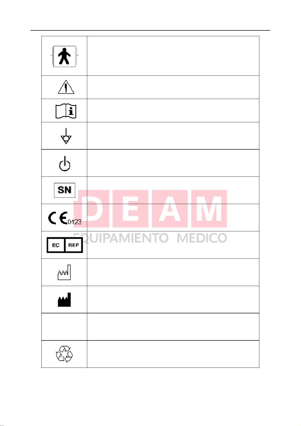
1.2.7 Explanation of Symbols on the Monitor
This symbol indicates that the equipment is IEC/EN60601-1 Type
CF equipment. The unit displaying this symbol contains an F-Type
isolated (floating) patient applied part providing a high degree of
protection against shock, and is suitable for use during
defibrillation.
- 6 -
Patient Monitor User Manual Intended Use and Safety Guidance
This symbol indicates that the instrument is IEC/EN 60601-1 Type
BF equipment. The unit displaying this symbol contains an
F-Type isolated (floating) patient applied part providing a high
degree of protection against shock, and is suitable for use during
defibrillation.
Caution
Consult Instructions for Use
Equipotential grounding system
Stand-by. It designates that the switch or switch position which
one part of the monitor has been switched on, while the monitor is
at the status of stand-by.
P/N
Serial number
The symbol indicates that the device complies with the European
Council Directive 93/42/EEC concerning medical devices.
Authorised representative in the European community
Date of manufacture
Manufacturer
Part Number
Recycle


- 8 -
Patient Monitor User Manual Installation of Monitor
Chapter 2 Installation of Monitor
Installation should be carried out by qualified service personnel, either by the hospital’s
biomedical department, or by EDAN Support.
For mechanical and electrical installation, you need technically qualified personnel with a
knowledge of english. Additionally, for monitor configuration, you need clinically qualified
personnel with a knowledge of the use environment.
NOTE:
1 The monitor configuration settings must be specified by authorized hospital
personnel.
2 To ensure that the monitor works properly, please read Chapter Safety Guidance,
and follow the steps before using the monitor.
2.1 Opening the Package and Checking
Visually examine the package prior to unpacking. If any signs of mishandling or damage are
detected, contact the carrier to claim for damage. Open the package and take out the monitor and
accessories carefully. Keep the package for possible future transportation or storage. Check the
components according to the packing list.
If there is any problem, contact the manufacturer or local representative immediately.
Check for any mechanical damage.
Check all the functions, cables and accessories.
2.2 Installing Wall Mount for the Monitor (Optional)
Figure 2-1

- 9 -
Patient Monitor User Manual Installation of Monitor
Figure 2-2
Figure 2-3
Installation Steps:
1. Outline along the part 1 edge against the wall to the desired location.
2. Drill 4 holes of 6mm in diameter in the wall, and knock the plastic nuts in the holes
completely.
3. Knock 4 screws in the plastic nuts, when tightening them, secure the channel (part 1) at the
desired location of the wall (as shown in Figure 2-1).
4. Slide the arm (part2) into channel (part1) as Figure2-2 shows to the desired location.
5. Tighten the manual screw and secure the arm (part2) at the desired position within the
channel (part1).
6. Face the side with duplexing piece of the device holding plate to the underside of the patient
monitor, fix it with an M4×25mm screw (as shown in Figure 2-3).
7. Pull out the fixing screw from the fixing hole.
8. At the same time, put the arm (part2) into the patient monitor with the device holding plate,
and secure the fixing screw totally through the fixing hole.
9. The patient monitor can be adjusted by a maximum of 15 degrees by rotating the black knob.
2.3 Connecting the Power Cable
Connection procedure of the AC power line:

- 10 -
Patient Monitor User Manual Installation of Monitor
50Hz/60Hz.
Make sure the AC power supply complies with the following specifications: 100V-240V~,
NOTE:
Connect the power line to the jack special for hospital usage.
NOTE:
When the battery configuration is provided, after the device is transported or stored, the
battery must be charged. Powering on without connecting AC power supply may cause
the device to malfunction. Switching on AC power supply can charge the battery no
matter if the monitor is powered on.
Apply the power line provided with the monitor. Plug the power line to INPUT interface of
the monitor. Connect the other end of the power line to a grounded 3-phase power output.
Connect to the ground line if necessary. Refer to Section1.2 Safety Guidance for details.
2.4 Powering on the Monitor
After you power on the monitor, LOGO information will be displayed on the screen.
WARNING
If any sign of damage is detected, or the monitor displays some error messages, do not
use it on any patient. Contact biomedical engineer in the hospital or Customer Service
Center immediately.
NOTE:
1 Check all the functions of the monitor and make sure that the monitor is in good
status.
2 If rechargeable batteries are provided, charge them after using the device every time,
to ensure the electric power is enough.
3 The interval between double pressing of POWER switch should be longer than 1
minute.
4 After continuous 360-hour runtime, please restart the monitor to ensure the monitor’s
steady performance and long lifespan.
2.5 Connecting Patient Sensors
Connect all the necessary patient sensors between the monitor and the patient.
NOTE:
For information on correct connection, refer to related chapters.
2.6 Checking the Recorder
If your monitor is equipped with a recorder, open the recorder’s door to check if paper is properly
installed in the slot. If no paper exists, refer to Chapter8 Recording for details.
- 11 -
Patient Monitor User Manual Introduction
Chapter 3 Introduction
3.1 General Information
The monitor integrates the functions of parameter measurement module, display, recording and
output to compose a compact, portable device. Its built-in replaceable battery provides
convenience for patient movement. On the high-resolution display screen, 7 waveforms and all
the monitoring parameters can be displayed clearly.
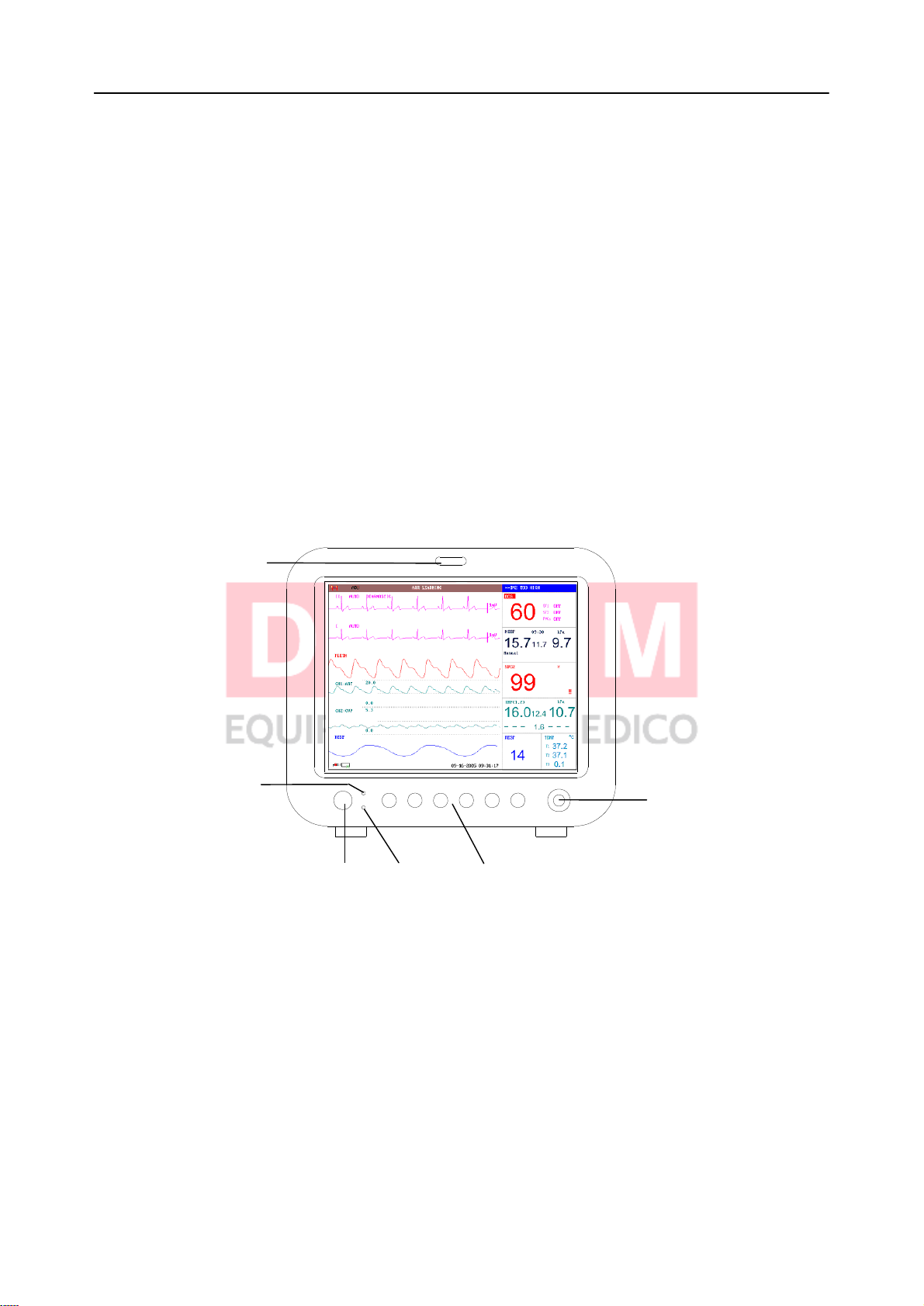
The POWER switch is on the left of the front panel (Figure 3-1, 3-2 ①). The POWER indicator
lights when the monitor is powered on (Figure 3-1, 3-2 ②). The CHARGE indicator shows the
charging status (Figure 3-1, 3-2 ③). The ALARM indicator flashes when the alarm is triggered
(Figure 3-1, 3-2 ④). The sockets of various sensors are on the left panel. Other sockets and the
power plug-in are on the rear panel. The recorder is on the right panel.
The monitor is a user-friendly device with operations conducted by a few buttons and a rotary
knob on the front panel (Figure 3-1, 3-2 ⑤⑥). Refer to Section 3.3 Button Functions.
④
②
Power
①
Main Freeze
Charge
③ ⑤
Silence Record
Start Menu
Figure 3-1 M9 Patient Monitor
⑥
- 12 -
Patient Monitor User Manual Introduction
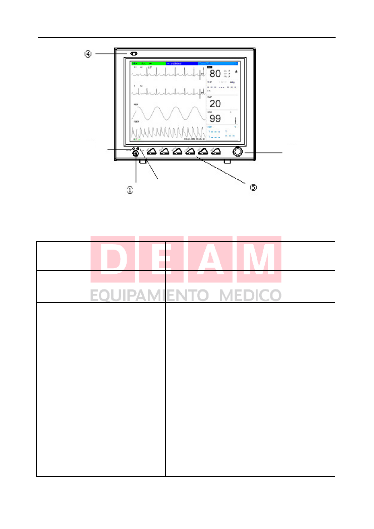
③
Product
models
Size (L×W×H)
Shell figure
/ Screen size
Functions
M9
Host:
322mm×150mm×285mm
Round /
12.1-inch
ECG/RESP, SpO2, NIBP, TEMP,
IBP, CO, CO2, GAS
M9A
Host:
322mm×150mm×285mm
Round /
10.4-inch
ECG/RESP, SpO2, NIBP, TEMP,
IBP, CO, CO2, GAS
M9B
Host:
320mm×150mm×265mm
Square /
10.4-inch
ECG/RESP, SpO2, NIBP, TEMP,
IBP, CO
2
M8
Host:
320mm×150mm×265mm
Square /
12.1-inch
ECG/RESP, SpO2,NIBP,TEMP,
IBP, CO
2
M8A
Host:
320mm×150mm×265mm
Square /
10.4-inch
ECG/RESP, SpO2,NIBP, TEMP,
IBP, CO
2
M8B
Host:
320mm×150mm×265mm
Square /
10.1-inch
Width_screen
ECG/RESP, SpO2, NIBP, TEMP,
IBP
②
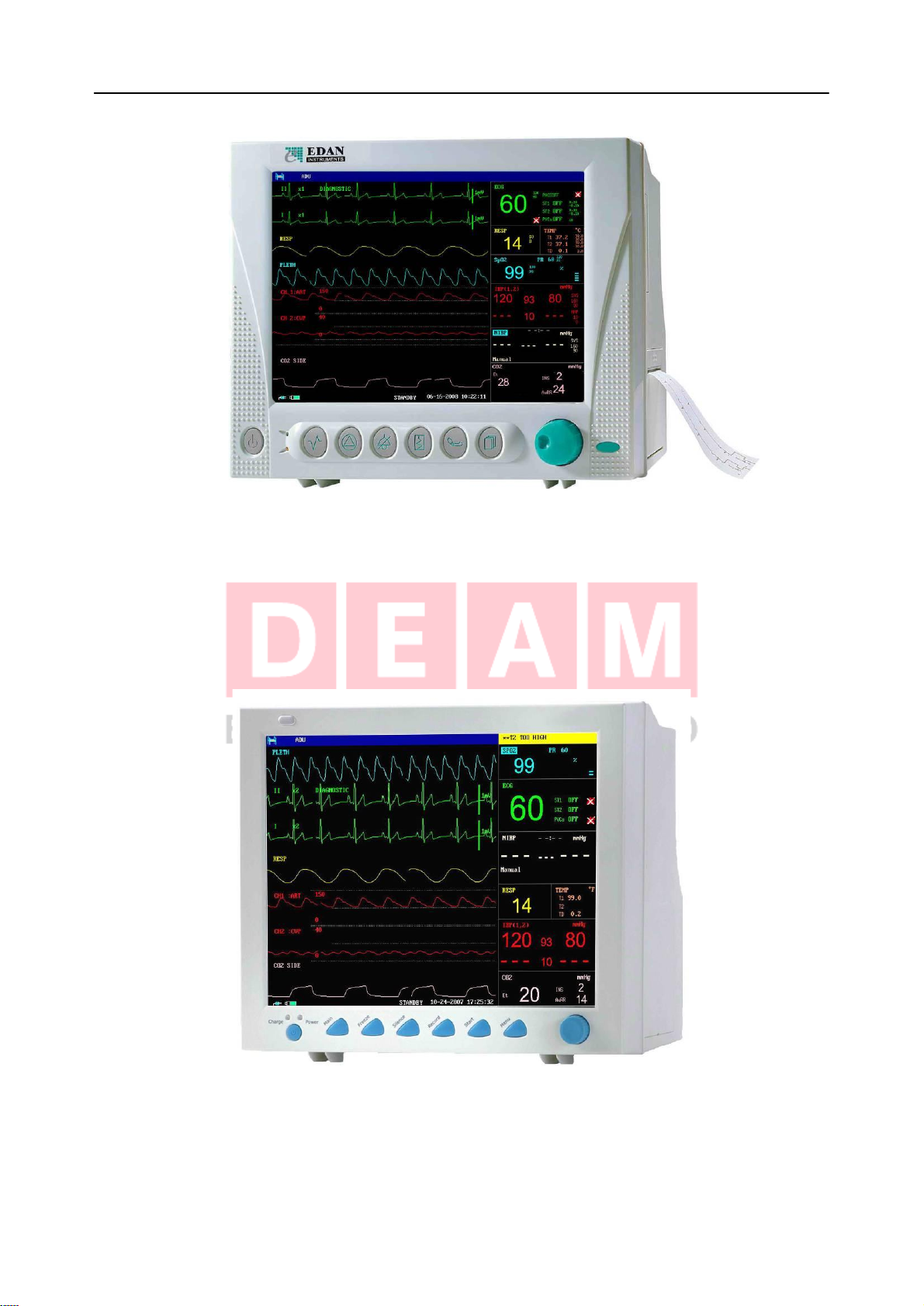
Figure 3-2 M8 Patient Monitor
The monitor has 6 models: M9, M9A, M9B, M8, M8A and M8B.
⑥
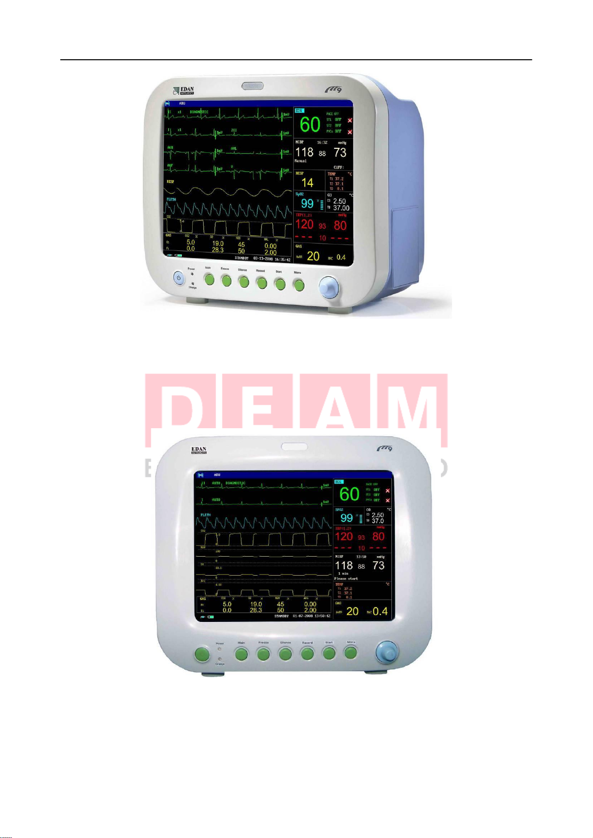
- 13 -
Patient Monitor User Manual Introduction
Figure 3-3 M9 Patient Monitor
Figure 3-4 M9A Patient Monitor
- 14 -
Patient Monitor User Manual Introduction
Figure 3-5 M9B Patient Monitor
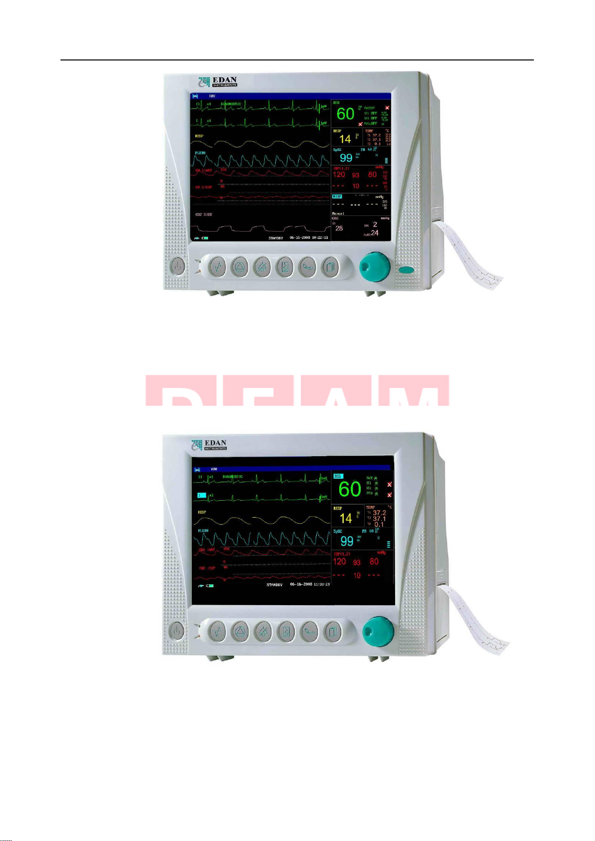
Figure 3-6 M8 Patient Monitor
- 15 -
Patient Monitor User Manual Introduction
Figure 3-7 M8A Patient Monitor
Figure 3-8 M8B Patient Monitor
The monitor can monitor the following parameters and waveforms:
ECG: Heart Rate (HR)

- 16 -
Patient Monitor User Manual Introduction
Maximum 7-channel/12-channel ECG waveform
Arrhythmia and ST-segment analysis (optional)
RESP: Respiration Rate (RR)
Respiration Waveform
SpO2: Oxygen Saturation (SpO2), Pulse Rate (PR)
SpO2Plethysmogram
NIBP: Systolic Pressure (SYS), Diastolic Pressure (DIA), Mean Pressure (MAP), PR (NIBP)
TEMP: Channel-1 Temperature (T1), Channel-2 Temperature (T2),
Temperature Difference between two channels (TD)
IBP: Channel-1 SYS, DIA, MAP
Channel-2 SYS, DIA, MAP
Dual-IBP waveforms
CO2: End Tidal CO2(EtCO2)
Inspired Minimum CO2(InsCO2)
Air Way Respiration Rate (AwRR)
CO2waveform
CO: Blood Temperature (TB)
Cardiac Output (CO)
GAS: Inspired or expired CO2(FICO2, ETCO2)
Inspired or expired N2O (FIN2O, ETN2O)
Inspired or expired O2(FIO2, ETO2)
Inspired or expired Anesthetic Agent (FIAA, ETAA):
HAL (Halothame)
ISO (Isoflurane)
ENF (Enflurane)
SEV (Sevoflurane)
DES (Esflurane)
Airway respiration rate (respiring time per minute, BPM), AwRR
Minimal Alveolar Concentration (MAC)
4 anesthetic gas waveforms (CO2, N2O, O2, AA)
The monitor provides extensive functions such as visual and audible alarms, storage for trend
data, NIBP measurements, alarm events, drug dose calculation, wireless network function and so
on.
3.2 Screen Display
The monitor is equipped with a high-resolution multicolor TFT LCD screen. The patient
parameters, waveforms, alarm messages, bed number, time, monitor status and other data can be
- 17 -
Patient Monitor User Manual Introduction
reflected from the screen.
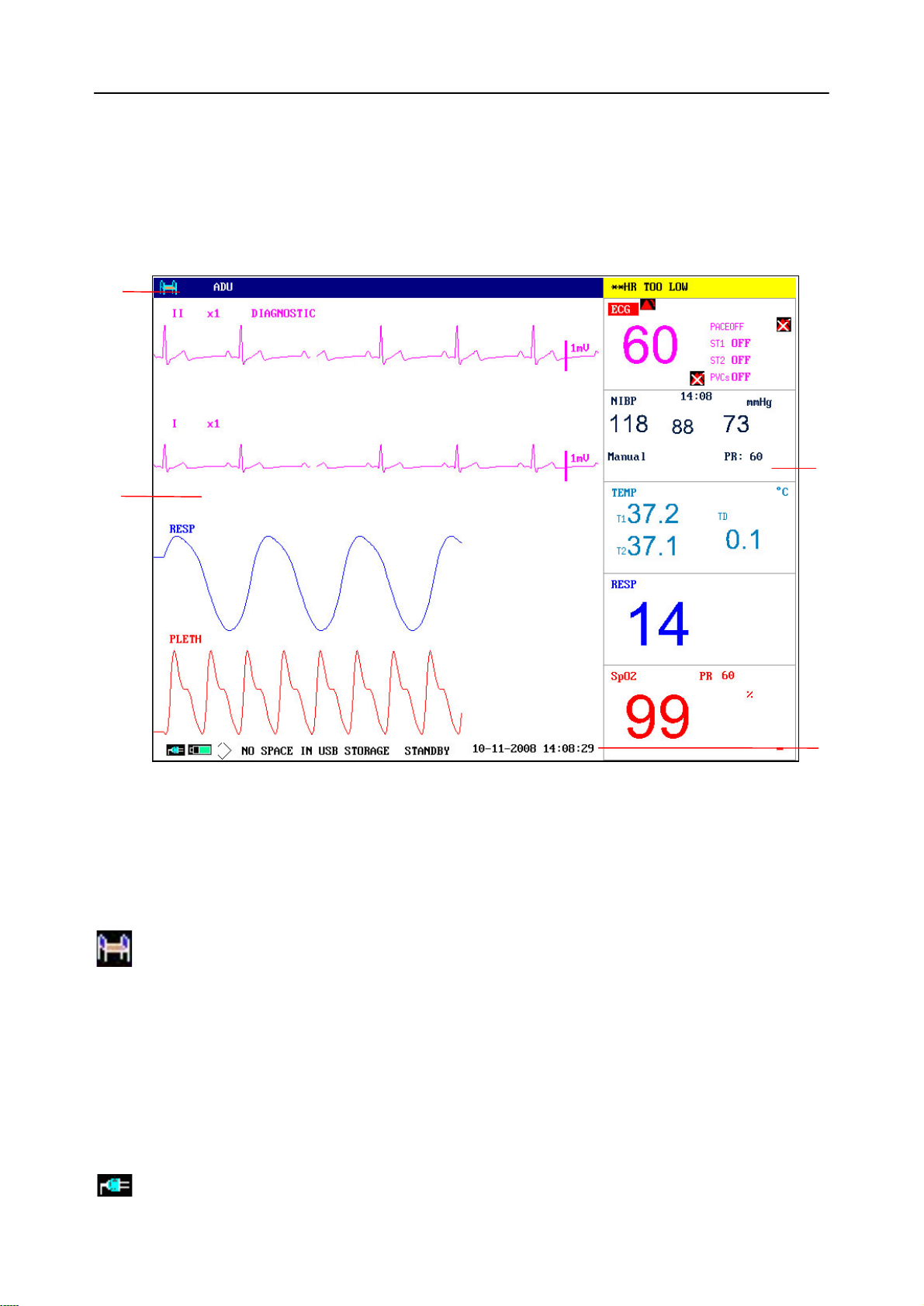
The screen is divided into three areas:
1 Information Area ① ④;
2 Waveform Area ②;
3 Parameter Area ③.
①
②
③
Figure 3-9 Main Display
Information Area
(
① ④
)
The Information Area is at the top and bottom of the screen, displaying the operating state of the
monitor and the status of the patient.
The information area contains the following data:
Bed number of the monitored patient
ADU Type of patient. Three options: Adult, Pediatric, Neonatal.
Name Name of the monitored patient, when the user inputs patient name, this
name will be displayed on the right side of the patient type. If the user
doesn’t input patient name, this position will be vacant.
10-11-2008 Current date
14: 08: 29 Current time
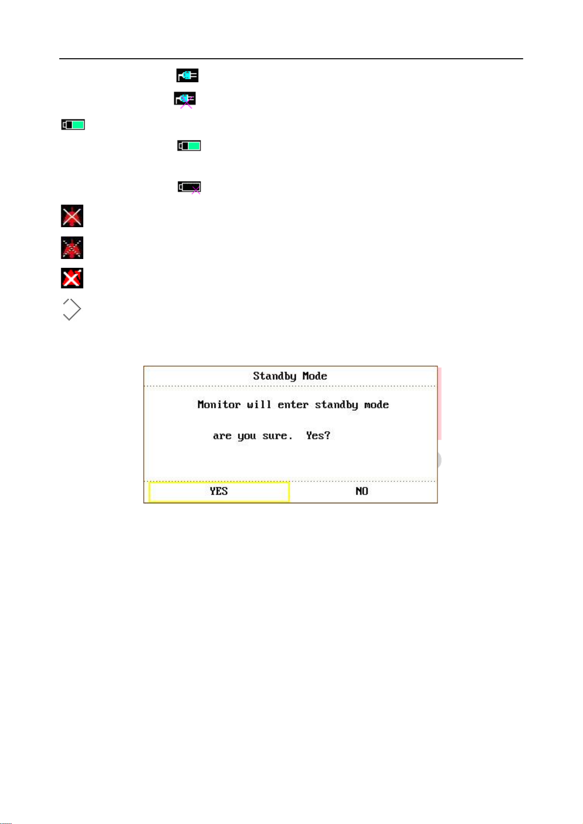
Indicates the status of mains power supply
④
- 18 -
Patient Monitor User Manual Introduction
means the mains power supply is on,
means the mains power supply is off.
Indicates the battery and its capacity;
gives information about remaining battery charge, estimated
operating time and maintenance requirements;
means there is no battery equipped in the monitor.
Indicates the audio alarm is turned off.
Indicates the audio alarm is paused.
Displays beside a parameter to indicate the alarm is turned off.
USB storage indicator
STANDBY Select this item to enter Standby mode, the dialog pops up:
Figure 3-10 Standby Mode
Select YES to enter Standby mode and display the current time; if you select NO, the monitor
will return to the main display.
Other information of the Information Area comes up only with respective monitoring status. They
are:
Signs indicating the operating status of the monitor and the sensors are displayed at the right
side of patient name.
Alarm message is displayed in the right most area.
“FREEZE” appears when the waveforms are frozen.
Waveform Area (②)
Seven waveforms can be displayed at the same time. The sequence of waveforms can be adjusted.
With the maximum configuration, the system can display 2 ECG waveforms, an SpO2waveform,
a respiration waveform (can be from ECG module), 2 IBP waveforms and a CO2waveform.

- 19 -
Patient Monitor User Manual Introduction
In the TRACE SETUP menu, all the waveforms are listed. The user can select the waveform to
be displayed, and adjust the display position. Refer to Section 4.8 Tracing Waveforms Selection
for details.
The name of the waveform is displayed on the upper left part of the waveform. The name of ECG
is user-selectable. Gain and filter way of this channel are displayed as well. A 1mV scale is
marked on the right of ECG waveform. The IBP waveform scale can also be selected according
to the actual requirement. Its range is described in the part: IBP Monitoring. In the IBP waveform
area, the waveform scale is displayed. The three dotted lines for each IBP waveform from up to
down represent respectively the upper limit scale, reference scale and lower limit scale. The
values of these three scales can be set. The specific method is given in the part: IBP Monitoring.
When a certain menu is displayed, some waveforms become invisible. Main display is restored
when you exit the menu.
The user may set up the rate to refresh the waveform. The method to adjust the refreshing rate of
each waveform is discussed in the setup description of each parameter.
Parameter Area
(③)
Parameter area is on the right of Waveform area, and parameters are displayed corresponding to
waveforms basically. They are:
ECG:
Heart Rate (Unit: beats per minute, bpm)
ST-segment analysis of Channel 1 & 2-ST1, ST2 (Unit: mV)
PVCs (Premature Ventricular Contraction) events (Unit: event/min)
SpO2:
Oxygen Saturation SpO2(Unit: %)
PR (Unit: BPM)
NIBP:
Systolic pressure, Mean pressure, Diastolic pressure (Unit: mmHg or kPa)
PR (NIBP) (Unit: BPM)
TEMP:
Temperatures of channel 1, channel 2 and their temperature difference: T1, T2, TD
(Unit:C or F)
RESP:
Respiration Rate (Unit: breath/min)
IBP:
The blood pressure of channel 1 and 2. From left to right, there are Systolic pressure,
Mean pressure and Diastolic pressure(Unit: mmHg or kPa)
CO2:
EtCO2(Unit: %, mmHg or kPa)
INS CO2(Unit: %, mmHg or kPa)
AwRR (Unit: times/minute)

- 20 -
Patient Monitor User Manual Introduction
CO:
① Menu
Press to call up the SYSTEM MENU. Refer to Chapter4 SYSTEM
MENU and Chapter9 Trend and Event for details.
② Start
Press to fill air into cuff and start blood-measuring. During the
measuring process, press the button to stop measure.
③ Record
Press to start a real-time recording. The recording time is set in RT
REC TIME of RECORD submenu.
④ Silence
When the SYSTEM MENU > MAINTAIN > USER MAINTAIN >
the alarm audio will be closed. At the same time, “ALARM
SILENCE ×× s” and will be displayed in the Information area.
When you repress it or the pause time is over, the system will resume
CO (Unit: liter/minute)
TB (Unit: C or F)
GAS:
Airway Respiring Rate (Respiring per minute)
Minimal Alveolar Concentration.
Alarm Indicator and Alarm Status
In normal status, the alarm indicator does not light.
When an alarm occurs, the alarm indicator will light or flash. The color of light represents the
alarm level. Refer to Chapter6 Alarm for details.
Refer to relative content of parameter for Alarm information and prompt.
Charge Indicator and Charge Status
To indicate the status of charging: When the battery is charged, the light color turns to orange.
3.3 Button Functions
All the operations to the monitor can be finished by several buttons and a knob. They are:
Figure 3-11 Buttons

- 21 -
Patient Monitor User Manual Introduction
the normal monitoring status, and “Alarm Pause ×× s” and icon will
vanish.
Pressing this button and holding for more than 3 seconds can turn off
the audio alarm. is shown in the Information area. Pressing or
holding the button again can resume the alarm.
NOTE:
Whether an alarm will be reset depends on the status of the
alarm cause. But pressing SILENCE button (suspend alarm)
can permanently shut off audio sound of the Lead Off or Sensor
Off alarms. So the user can exit the Alarm Silence Status by
Technical Alarm.
⑤ Freeze
In normal mode, press this button to freeze all the waveforms on the
screen. In FREEZE mode, press this button to restore the waveform
refreshing.
⑥ Main
Press this button to return to the main interface.
⑦ Rotary Knob
The user can use the rotary knob to select the menu item and modify
the setup. It can be rotated clockwise or anticlockwise and pressed.
The user can use the knob to realize the operations on the screen, in
the SYSTEM MENU and parameter menu.
Method to Use the Knob to Operate on the Screen:
The rectangular mark on the screen that moves with the rotation of the knob is called “cursor”.
Operation can be performed at any position at which the cursor can stay.
When the cursor is in the waveform area, the user may immediately modify the current setup.
When the cursor is in the parameter area, the user may open the setup menu of the corresponding
parameter module so as to set up the menu items of the module.
Operating method:
Move the cursor to the item where the operation is required.
Press the knob.
One of the following four situations may appear:
1. The cursor with background color may become a frame without background color,
which implies that the content in the frame can change with the rotation of the knob.
2. Menu or measuring window may appear on the screen, or the original menu is
replaced by the new menu.
3. A check mark “√” appears at the position, indicating that the item is confirmed.
4. The system immediately executes a certain function.
 Loading...