

Page 1

Red Bull Racing RB7: Step by Step
™
370
Stages 77-80
Pack 20
RB7
RADIO CONTROLLED • BUILD IT YOURSELF • NITRO ENGINE
™
Page 2

Red Bull Racing RB7: Step by Step
™
371
™
RB7
Editorial and design by Continuo Creative, 39-41 North Road, London N7 9DP
All rights reserved © 2014 De Agostini UK Ltd, Battersea Studios 2, 82 Silverthorne Road, London SW8 3HE
RED BULL RACING RB7 complies with CE regulations.
NOT SUITABLE FOR CHILDREN UNDER THE AGE OF 14. THIS PRODUCT IS NOT A TOY AND IS
NOT DESIGNED OR INTENDED FOR USE IN PLAY. ITEMS MAY VARY FROM THOSE SHOWN.
Photo credits: All photographs copyright
© DeAgostini
Visit our website www.model-space.com
Intro
The GX21 silencer system
The GX21 air lter
Cleaning the air lter
The RC power switch
Stage 77
Fitting the silencer
Stage 78
Fitting the air lter
Stage 79
Fitting the RC power switch
Stage 80
The battery box and antenna tube
Page 372
Page 374
Page 376
Page 378
Page 381
Page 389
Page 395
Page 397
Contents
Page 3
Red Bull Racing RB7: Step by Step
™
372
THE GX21 SILENCER
SYSTEM
UNLIKE THE SILENCER SYSTEM OF A FOUR-STROKE ENGINE, THAT OF A TWOSTROKE NOT ONLY EXPELS THE EXHAUST GASES AND REDUCES THE NOISE, BUT
ALSO HELPS COMPRESS THE FUEL-AIR MIXTURE IN THE COMBUSTION CHAMBER.
On a four-stroke engine, expelling the exhaust gases and
reducing noise are the main tasks of the silencer system,
but the silencer of a two-stroke – such as your GX21 – is
used primarily to optimise its performance.
With a four-stroke, the inlet and exhaust ports of the
combustion chamber are opened and closed by valves.
When the piston moves downwards on the rst (induction)
stroke, the inlet valve opens and the fuel-air mixture ows
into the combustion chamber. After the compression and
combustion strokes comes the exhaust stroke, when the
exhaust valve opens and the piston drives the exhaust
gases out of the chamber.
The situation is dierent with the two-stroke engine,
where it is the movement of the piston that opens or
closes the inlet and exhaust ports (see the intro section in
Pack 16). When the piston is at the top of the combustion
chamber, it is closing o both the inlet and the exhaust
ports. As it moves downwards on the combustion stroke, it
opens the exhaust port and the exhaust gases are ejected
by the pressure generated by the explosion. As the piston
moves further downwards, it also opens the inlet port,
while suction is created in the combustion chamber by the
escaping exhaust gases. Since both ports are open and the
piston is at the bottom of the cylinder, the fuel mixture is
drawn not only into the combustion chamber but also into
the silencer system. This is a really undesirable eect, since
it means that a portion of the fuel-air mixture can escape
unused and is wasted.
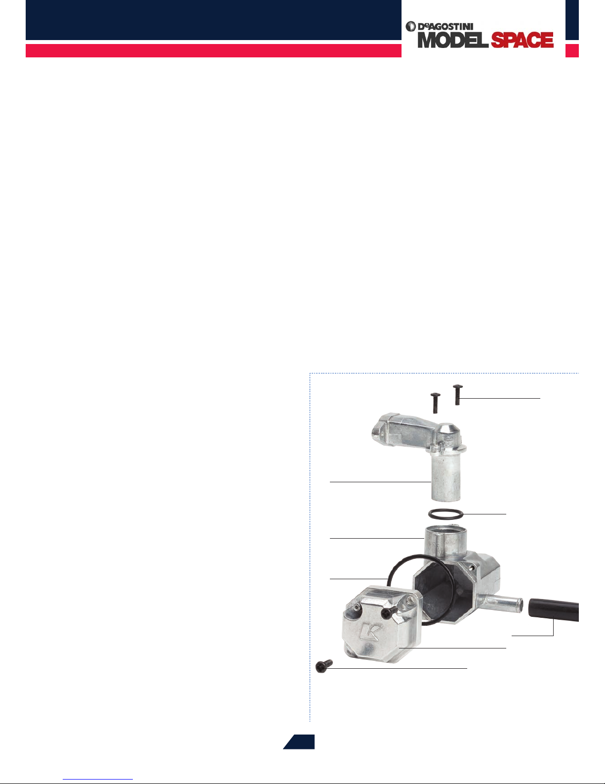
Dome-headed screws
O-ring
O-ring
Silencer cap
Silencer (expansion chamber) assembly
Manifold
Tailpipe
The GX21 silencer system
components
Dome-headed screw
Page 4
Red Bull Racing RB7: Step by Step
™
373
In the 1950s, East German motorcycle engineer Walter
Kaaden converted this disadvantage into an advantage.
He designed a system that prevented the unburnt fuel-air
mixture from owing out with the exhaust and at the same
time led to a considerable increase in engine performance:
the tuned pipe.
THE RESONANCE EFFECT
Basically, this system consists of nothing more than an
expansion chamber in the silencer pipe. It is shaped so
that the exhaust gases do not escape freely but are slowed
down, and some of the exhaust gas is trapped. The length
of the pipe and the volume of the expansion chamber are
selected so that the exhaust gases resonate in time with the
piston as it goes up and down – they expand as the piston
descends and are reected back towards the combustion
chamber as it rises again. In this way, the silencer system
causes a stronger compression of the mixture in the
combustion chamber.
To achieve the resonance eect, the cross-section of
the silencer pipe downstream of the exhaust port must
increase. In the case of your RB7 racer this occurs at the
transition from the manifold to the main chamber of the
silencer. This creates suction, which helps to ush the burnt
gases from above the piston and at the same time speeds
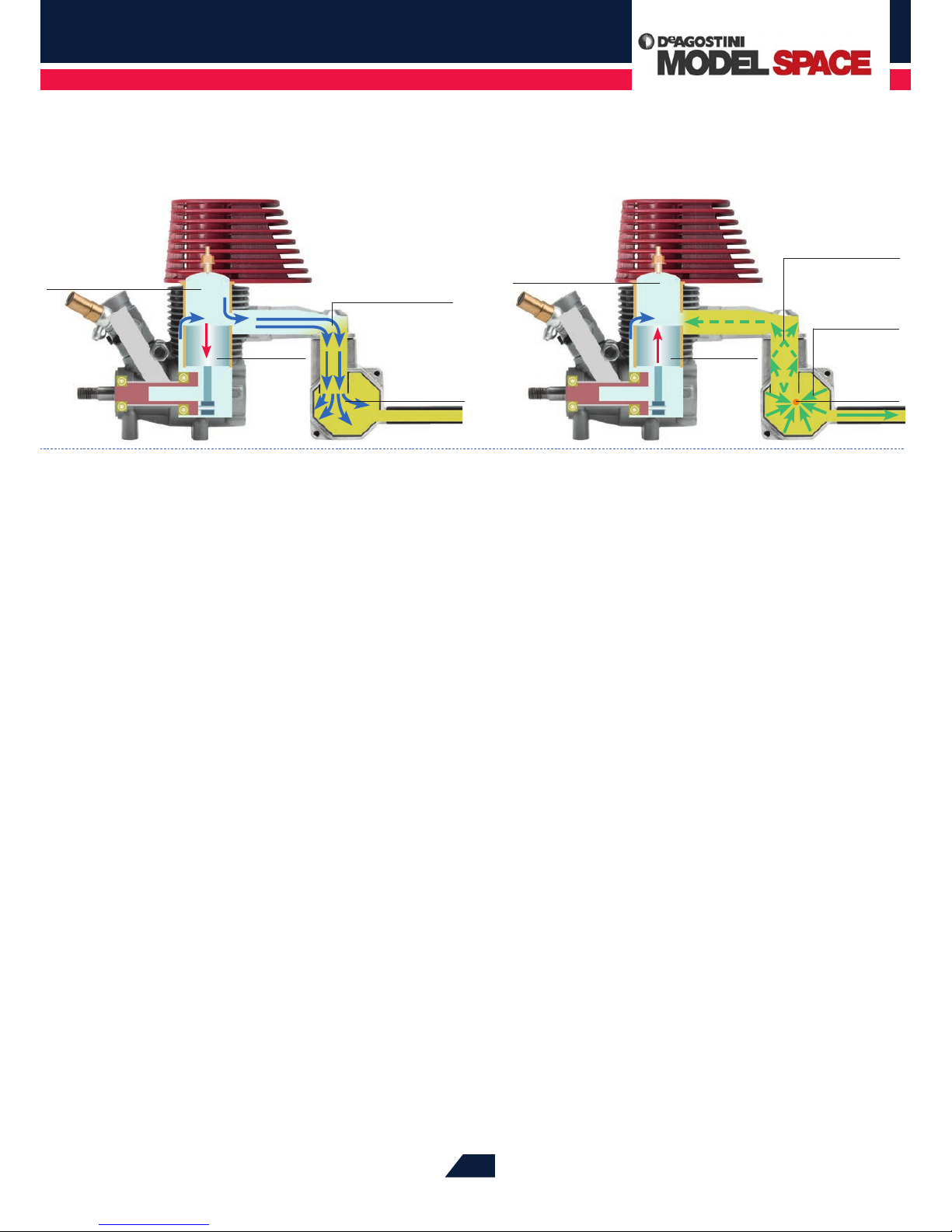
These two diagrams illustrate operation of the expansion chamber. Fresh
mixture ows into the manifold, but is forced back into the combustion
chamber by the reected exhaust gases.
Fresh mixture ows into the
combustion chamber
The mixture in
the combustion
chamber is
compressed more
The exhaust
gases
ow into
the expansion
chamber
Piston descends Piston rises
Reected
exhaust gases
ow back from
the resonance point
Resonance
point
The exhaust gases
are reected o
the walls
A portion of the
mixture ows into
the manifold
up the ow of fresh mixture into the combustion chamber
(see diagram above left). When the exhaust gases have
expanded, they collide with the walls of the expansion
chamber, and because the cross-section of the silencer
system narrows again towards the tailpipe, only a small
proportion of the gases can escape. Most of the gases are
reected back from the walls of the expansion chamber
and are concentrated at the so-called resonance point (see
diagram above right).
The resulting excess pressure pushes some of the exhaust
gases towards the manifold, forcing the fresh mixture that
has owed into it back into the combustion chamber. Only
when the piston rises again and closes the exhaust port will
the reected exhaust gases move through the tailpipe to
the outside atmosphere. This releases the pressure build-up
and the exhaust gases of the next combustion cycle can
ow into the expansion chamber.
The challenge in producing the resonance eect is to
match the oscillation frequency of the exhaust gases in the
silencer to the speed of the engine. This is dicult, because
the resonant frequency of the silencer system is xed at
a certain value dened by its shape and size, while the
speed of the engine varies from 3,000rpm when idling to
over 30,000rpm at full throttle. The silencer system of your
GX21 is designed so that the resonance eect starts when
the extra power can be most eective – when accelerating
out of a corner. This corresponds to an engine speed of
24,000rpm.
Piston descends Piston rises
Page 5
Red Bull Racing RB7: Step by Step
™
374
THE GX21 AIR FILTER
ANY DIRT ENTERING THE GX21 ENGINE THROUGH THE AIR INTAKE COULD DAMAGE
ITS CARBURETTOR, PISTON AND CYLINDER. A FINE AIR FILTER ENSURES THAT DIRT
PARTICLES CANNOT PENETRATE INTO THE INSIDE OF THE POWER UNIT.
The core of the GX21 air lter unit is a ne-pored foam
element 23mm in diameter and 20mm long. The centre of
the cylindrical element has a 15mm bore, which is pushed
onto a star-shaped projection on the lter base. The
cleaned air is sucked into the carburettor through a hole in
the base, also about 15mm in diameter.
FILTERING THE FINEST PARTICLES
The element is held in place by a plain plastic disc with
a diameter of 21mm (slightly smaller than that of the
element), xed onto the upper end of the star-shaped
projection by a single screw. Because the element is
slightly compressed from end to end, the thickness of the
cylindrical wall through which the air is sucked is about
4mm. Dust grains and other ne particles get trapped in
the ne pores of the foam.
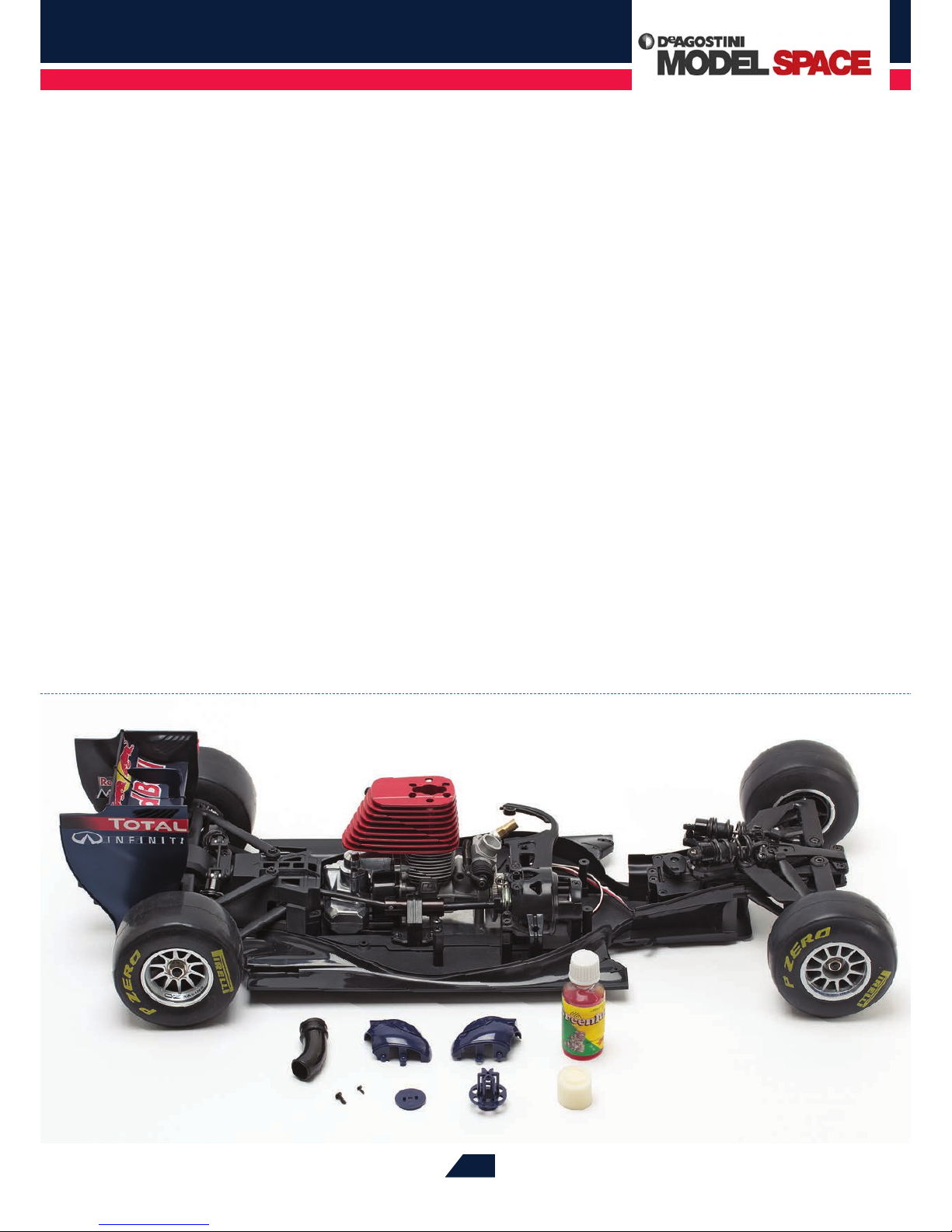
The components of the air lter, when assembled, will t onto the
carburettor, which can be seen here just in front of the red cylinder head
of the GX21 engine.
Page 6
Red Bull Racing RB7: Step by Step
™
375
The air lter unit is tted inside the right and left parts
of the driver’s helmet in the running bodywork. This
concealment is necessary because there is no room
beneath the bodywork of the model to house the engine
assembly. Because of this space restriction, the air lter
has to protrude from the body somewhere in the area
of the cockpit, and the obvious solution to the problem
of siting it was to integrate it with the driver’s helmet.
In this way, this indispensable but somewhat inelegant
technical component is hidden inside one of the car’s most
important external details, decorated with authentic logos.
A slot below the helmet visor, plus six semi-circular
openings at the base of the air lter in the ‘neck’ of the
helmet, allow a good supply of clean air to be safely sucked
into the engine. From the lter, the cleaned air passes
through a curved rubber pipe, 50mm long, which feeds it
into the carburettor.
OPTIMISING FILTER PERFORMANCE
For the air lter to do its job of ltering ne particles
eectively, the foam rubber insert must be impregnated
with a specially formulated air lter oil (see photograph
above), which is available from model shops and online.
This fairly viscous lubricant narrows the pores of the foam,
making the lter even ner, and it also helps the foam to
create an airtight seal at the joins between the element and
the base and the element and the lter cap. This airtight
seal ensures that no stray dirt particles can sneak under or
over the ends of the element and into the engine.
After ve tanks of fuel have been used, the air lter
should be removed and cleaned. To do this, you have to
split open the driver’s helmet to remove the lter assembly,
then take the lter apart so that you can clean and re-
lubricate the foam element.
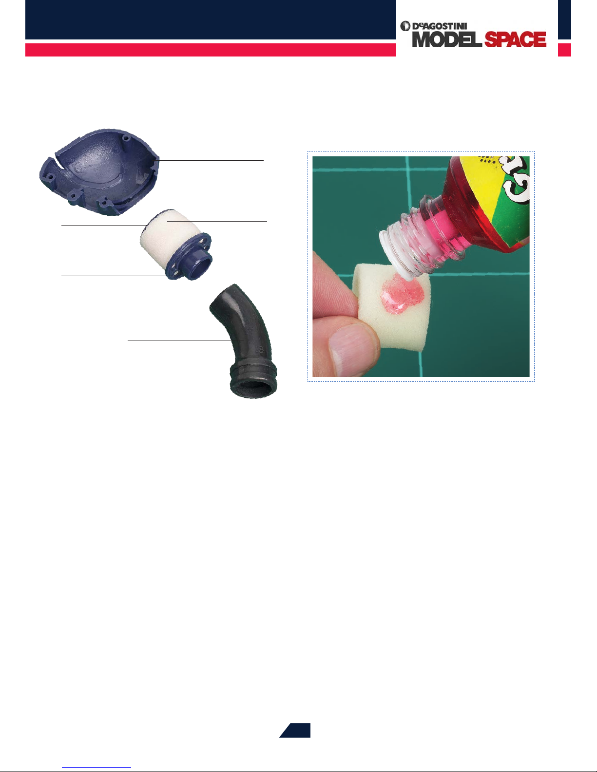
It’s advisable to saturate the lter element with air lter oil before tting it
onto the base. Knead the element to work the oil into it and distribute it
evenly across the element’s exterior.
Right helmet air lter cover
Air lter cap
Air lter element
Air lter base
Air lter pipe
The air lter unit is concealed within the driver’s
helmet, and a rubber pipe connects it to the
GX21 engine.
Page 7
Red Bull Racing RB7: Step by Step
™
376
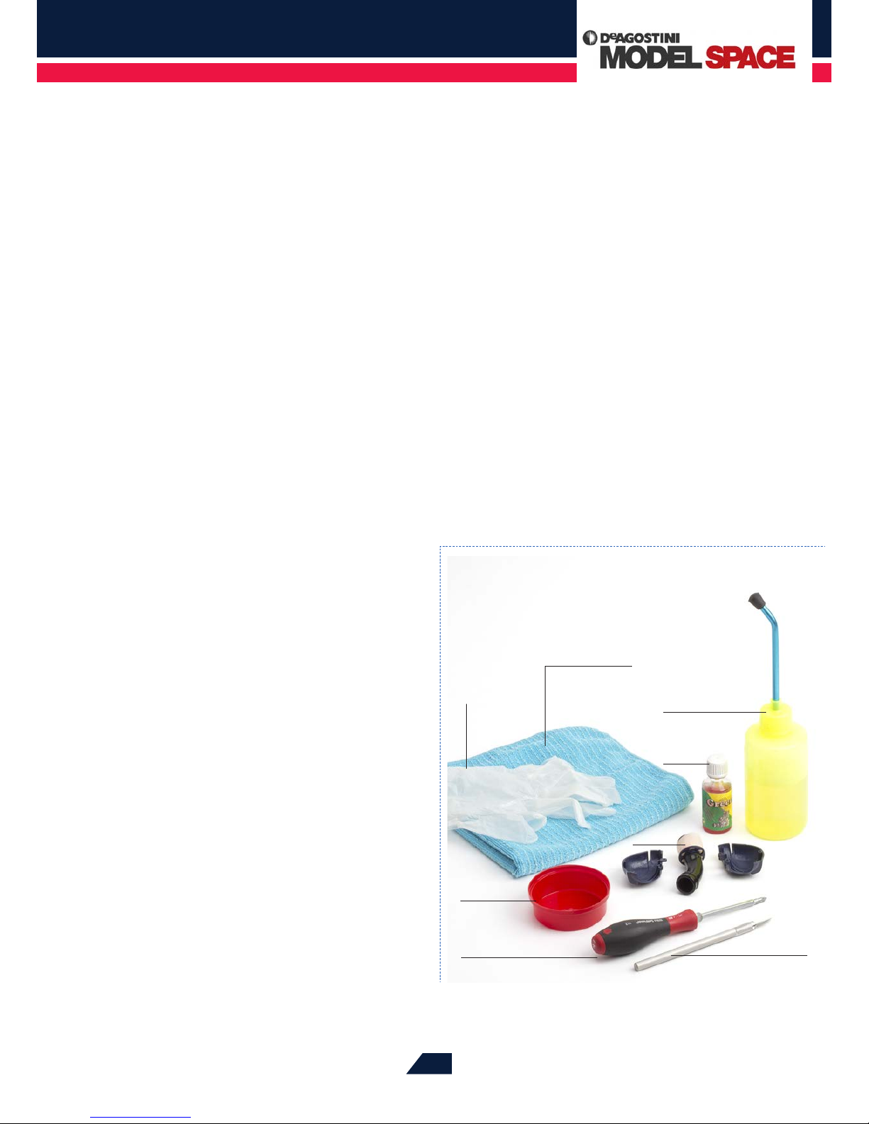
Some nitro fuel
Phillips screwdriver
(size 1)
Absorbent cloth
Small container
Air lter
Air lter
oil
Protective
gloves
Craft knife
To clean the air lter, you will need
these tools and materials.
CLEANING THE
AIR FILTER
TO PROTECT THE ENGINE FROM CONTAMINATION AND TO INCREASE ITS LIFESPAN,
YOU SHOULD GIVE THE AIR FILTER A THOROUGH CLEAN AT REGULAR INTERVALS.
HERE’S HOW YOU DO IT.
The air lter of your RB7 model contains a cylindrical
foam insert. This traps grains of dust and dirt that would
otherwise be carried along with the air sucked into the
carburettor and then into the cylinder, where they could
cause damage to the cylinder liner. When your RC car is
running, the air lter intake is only a few centimetres above
the ground. So as well as having to lter out the dust that
exists in the air, it has to deal with dirt from the track and
the residue of worn tyres. Consequently, the lter can
become clogged after quite a short time. The engine no
longer receives enough air to burn the fuel in the cylinder
completely, and the result is a reduction in engine power.
CLEANING THE FILTER
Depending on the condition of the track, it is advisable to
clean the air lter at intervals of ve to ten tanks of fuel.
Cleaning it doesn’t take long, and the process requires little
eort. The tools and materials needed are illustrated in the
photograph on the right, and they include items that you
may already have in your RC workshop case. The cleaning
agent is the same nitro fuel that you use to run your car.
Please note that this uid can cause skin irritation, so
make sure to protect yourself by wearing gloves when you
use it to clean the lter. Just follow the steps on the next
page, and your GX21 engine will reward you by delivering
consistent performance.
Before any prolonged period in which the engine will not
be used, you can supplement this regular basic cleaning
of the lter element by washing it in a bowl of warm water
containing a little dishwashing liquid, which will remove
all traces of oil residue. Then place it in clean water to rinse
away all the detergent.
Page 8
Red Bull Racing RB7: Step by Step
™
377
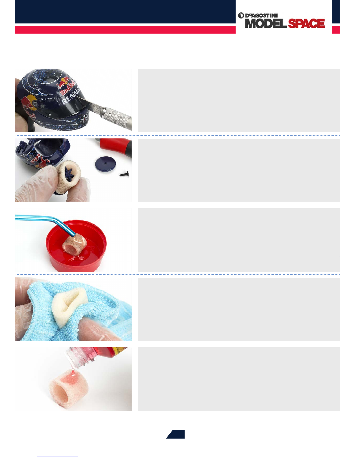
The air lter of the GX21 engine is concealed inside the driver’s helmet. To open the two half-shells
of the helmet so that the air lter can be reached, you have to cut through the two decorative
stickers on the front section of the helmet because they cross the join. It is best to do this with a
sharp craft knife or cutter. The pieces concerned are the sticker on the helmet visor and the one
that extends across the chinguard of the helmet. The Red Bull logo on the visor is already made of
two halves so it does not need to be divided. Position the tip of the blade at the top edge of the
visor and slide it carefully downwards.
After cutting the two stickers on the front of the helmet, the half-shells of the helmet can be pulled
apart enough to allow the air lter to be removed from its holder. To do this, loosen the top cover of
the lter by undoing the screw in the centre with a size 1 Phillips screwdriver. Now you can pull the
dirty foam lter element from the base of the lter. Wear gloves when doing this – the dirt particles
could lead to skin irritation.
After a further rinse with nitro fuel, place the lter element on an absorbent, lint-free piece of cloth
or on kitchen paper. Fold the absorbent material over the element, and squeeze the foam-rubber
cylinder thoroughly between the two layers of cloth or paper. Now rub the material gently over the
lter surface, so that it picks up any dust particles remaining in the foam after the rinsing process.
Hold the element up to the light to check the progress of the cleaning. If necessary, repeat the
rinsing and drying procedure until all the oil and dirt has been removed.
To clean the lter element, put it in a small container, such as the lid of a spray can. Drip nitro fuel
onto the element until it is saturated. (Again, wear gloves when doing this.) The fuel will dissolve
the old air lter oil and loosen any dirt residues that have built up in the pores of the element.
Vigorously squeeze the fuel-soaked element several times with your ngers (wearing gloves!) to
distribute the fuel throughout the foam. This process will remove the coarse dirt particles trapped
in the element, and they will settle on the bottom of the container.
To ensure the optimum performance of the ne-pored foam lter, you should soak it with air lter
oil after cleaning. This air lter oil is available in model shops and online, and its thick consistency
ensures that even the nest dust particles are retained. Put a few drops on the lter insert and
knead it well to work the oil into the pores. Now you can reassemble the air lter and t it back in
place between the half-shells of the driver’s helmet. For more information about the air lter and
detailed instructions for tting it, see Stage 78.
Page 9
Red Bull Racing RB7: Step by Step
™
378
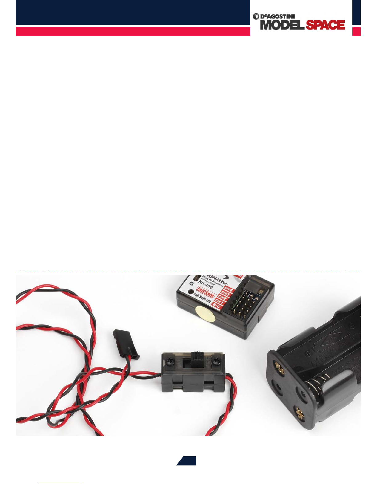
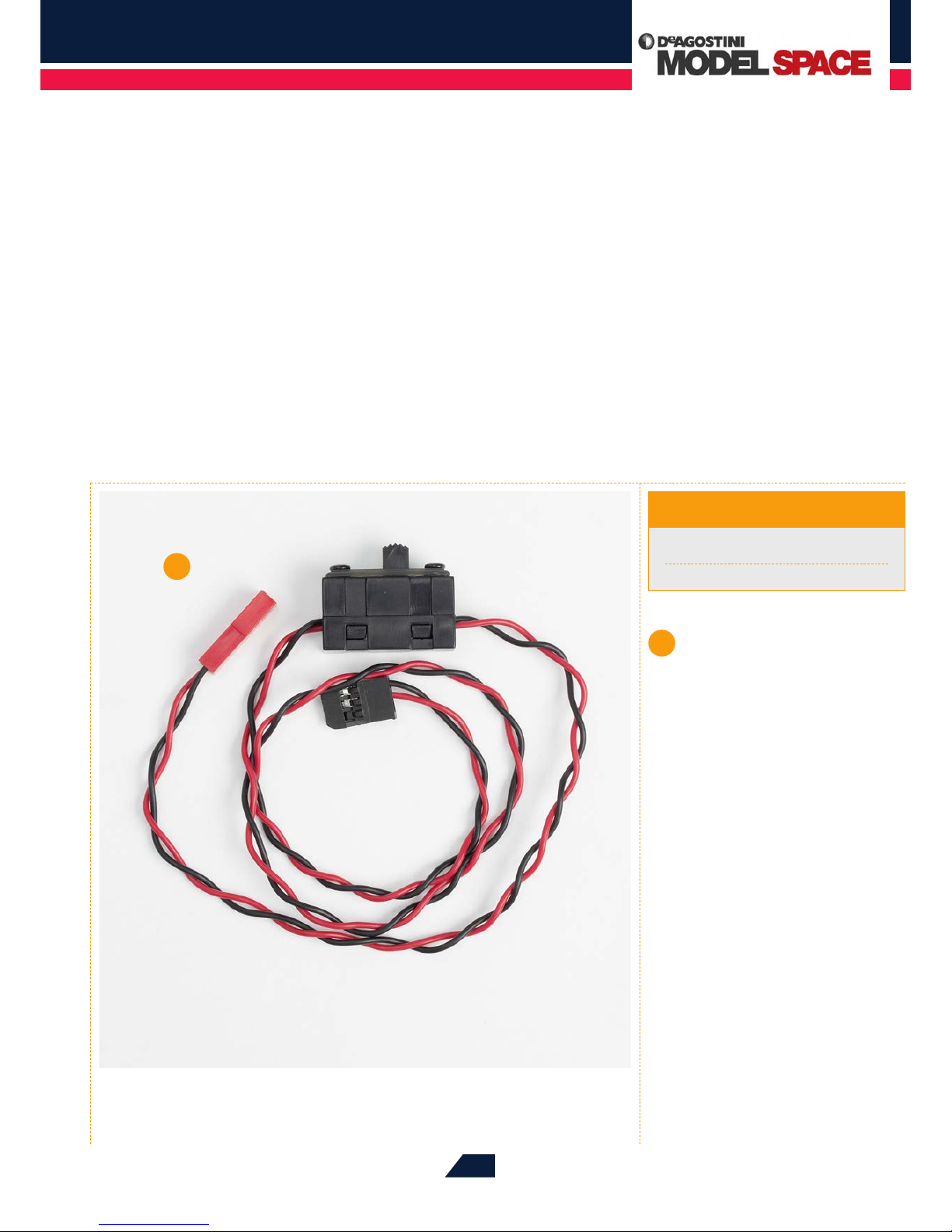
The RC power switch and its cables, seen here in the centre of the picture,
connect the RC receiver, at the top of the picture, to the battery box, on the
right.
THE RC POWER SWITCH
YOUR RB7 MODEL’S RC RECEIVER AND SERVOS ARE SUPPLIED WITH ELECTRICAL
POWER FROM ITS BATTERIES. THERE IS NO NEED TO MAINTAIN THIS POWER
SUPPLY WHEN THE CAR IS NOT IN USE, SO THE RC SYSTEM IS FITTED WITH A
SWITCH TO BREAK THE CIRCUIT.
With this pack, you will receive the RC power switch, the
rst electrical component of your model. The switch marks
the beginning of a new phase of the build, in which you will
t the components of the onboard control system – the RC
receiver and the throttle and brake servos – to the chassis
and the RC box.
BETWEEN BATTERY AND RECEIVER
The switch connects the battery box and the RC receiver
of your RB7 model. This arrangement means that is tted
at the most eective point in the circuit, because the two
servos of your model obtain their electrical power via
the receiver. When you use the switch to disconnect the
receiver from the power source, you are also disconnecting
the servos, so there’s no need for them to have individual
switches.
Page 10
Red Bull Racing RB7: Step by Step
™
379
The switch itself is a slide switch. Connected to it are a
pair of two-core cables (one core with red insulation, the
other black). These cables are soldered to the switch, which
is housed in a rectangular plastic casing. The on and o
switching process is carried out by a slider on the top of the
switch, which remains in whichever position is selected.
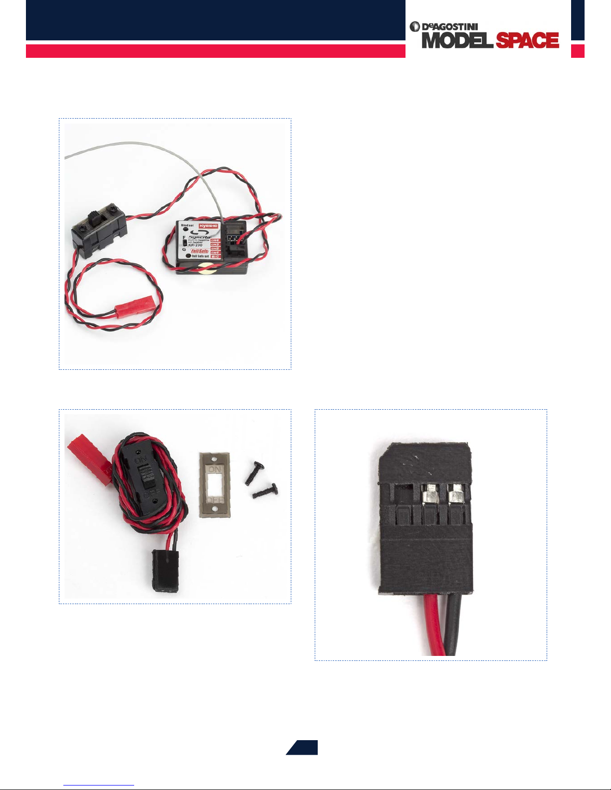
The ON and OFF markings are on a cover plate surrounding
the slider. You have to remove this plate when you mount
the switch on the right chassis plate of your model, so
always make sure that the plate is the right way round
when you replace it.
The plugs of the two cables attached to the switch are
dierent colours, and the cable with the red plug will be
connected to the battery box and the one with the black
plug to the receiver. When the slider is nearer to the cable
with the red plug, the switch is sitting in its OFF position
and the RC receiver and the two servos are disconnected
from the batteries.
When mounting the switch on the right chassis plate, you rst need to
remove its cover plate by removing the two retaining screws. This plate also
carries a visual indication of whether the switch is in the ON or OFF position,
so make sure that it is the right way round when you replace it.
The cable with the black plug connects the switch to the receiver.
The red and black wires are securely clamped to the metal contacts
in the plastic body of the plug.
The switch is connected upstream of the receiver, from which the servos
receive their power.
Page 11
Red Bull Racing RB7: Step by Step
™
380 380
Page 12
Red Bull Racing RB7: Step by Step
™
381
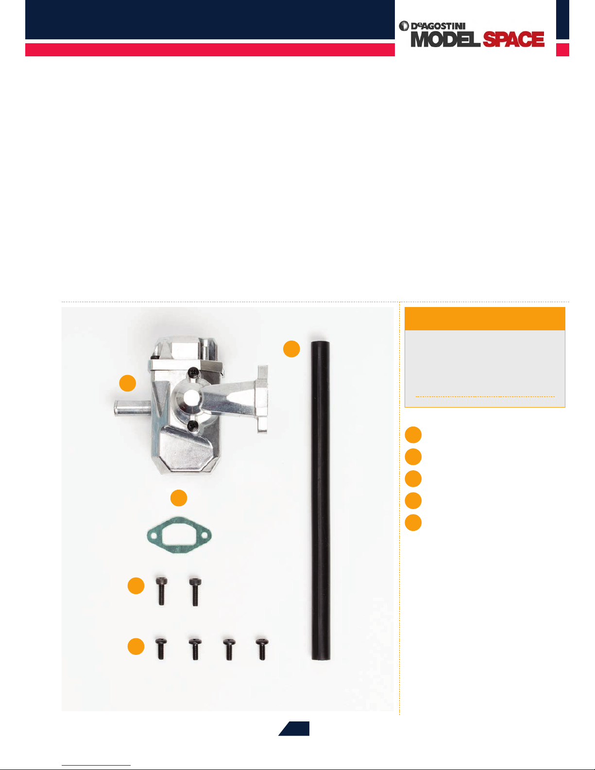
COMPLETE THE MAIN BUILD OF YOUR RB7’S GX21 ENGINE BY FITTING
IT WITH ITS PRE-ASSEMBLED SILENCER SYSTEM, AND THEN MOUNT IT ONTO
THE CAR’S CHASSIS.
FITTING THE
SILENCER
1
5
2
4
3
Phillips screwdriver (size 02)
2.5mm Allen key
Angled needle-nose pliers
Grease (from Stage 38 or Stage 63)
Toothpick
Tools & Materials
1
Silencer (pre-assembled)
2
Tailpipe
3
Gasket
4
2 cap screws 3 x 10mm
5
4 dome-headed screws
3 x 8mm
Stage 77
Page 13
Red Bull Racing RB7: Step by Step
™
382
03
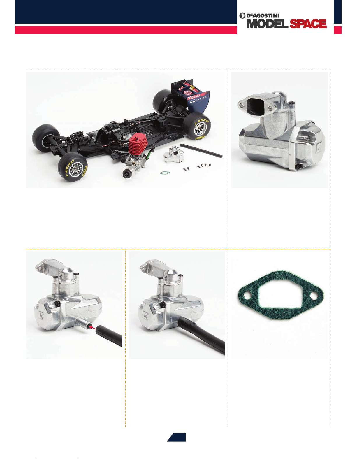
Position the silencer on your
work surface with the manifold
facing away from you, then push the tip
of the tailpipe over the outlet pipe, as
indicated by the red arrow.
04
Push the tailpipe over the outlet
until it rests snugly against the
body of the silencer, as shown.
05
The gasket is shaped to match
the manifold’s ange, and will
help form an airtight seal between the
engine and the manifold. It is made of a
heat-resistant material.
01
For this assembly session, you will need your RB7 chassis assembly, your GX21
engine and the parts supplied with this stage.
02
The exhaust manifold is attached
to the top of the body of the
silencer, and its opening has a ange
that will match up to the one at the rear
of the engine.
Page 14
Red Bull Racing RB7: Step by Step
™
383
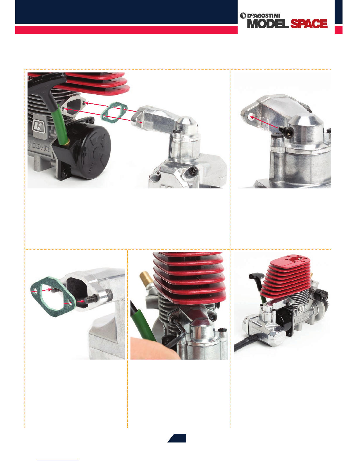
08
Align the gasket with the
manifold and push it over the
ends of the cap screws, as indicated by
the arrows.
09
Making sure that the gasket stays
in position, t the manifold to
the exhaust port of the engine, as shown
in the photo for Step 06, then use the
Allen key to tighten both cap screws
fully and join the parts securely.
10
This completes the assembly of
your RB7’s GX21 engine, which
should now look like this.
06
The photo above shows how the silencer and engine will be joined. The two must
be perfectly aligned, with the gasket sitting between the manifold and the engine’s
exhaust port. The parts will be held together tightly by two screws, which will compress the
gasket to form an airtight seal.
07
Place a 3 x 10mm cap screw
through each of the holes on the
manifold, inserted from the rear.
Page 15
Red Bull Racing RB7: Step by Step
™
384
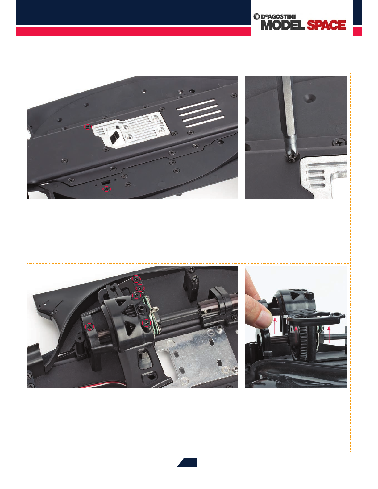
13
Turn the assembly over so that you can access the top of the chassis, then use the
screwdriver to undo and remove the ve circled screws from the gearbox cover
(the centre upper plate). Again, keep these to one side as you will need them later.
14
When you’ve removed all the
screws, carefully lift the gearbox
cover away from the chassis and put it to
one side.
11
The next step is to prepare the chassis to hold the engine. To do this, lay your RB7
chassis on your work surface with the underside facing upwards. The two screws
circled in the picture will be removed in the next step.
12
Undo the screws using a Phillips
screwdriver and keep them safely
to one side, because you will be using
them at a later stage.
Page 16
Red Bull Racing RB7: Step by Step
™
385
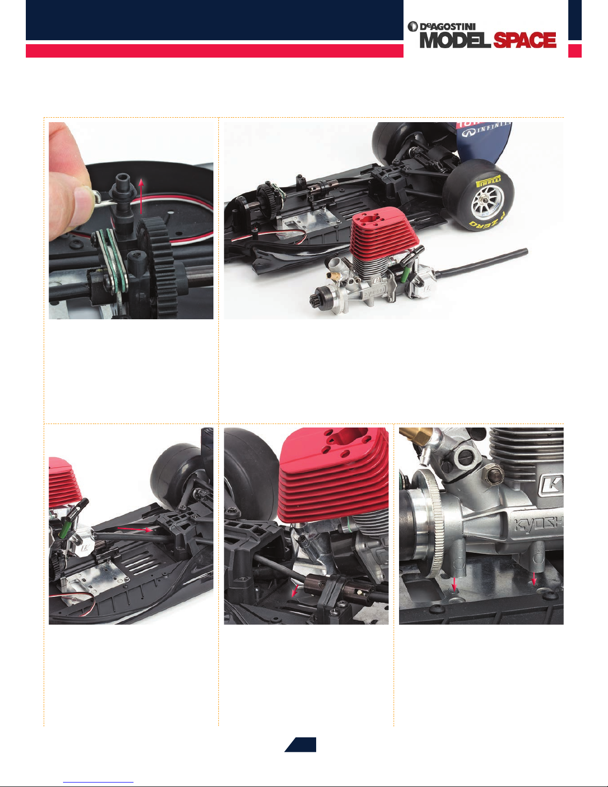
17
Hold the engine above the
chassis with the silencer’s tailpipe
facing the rear. Lower it towards the
surface of the chassis, with the tailpipe
feeding into the rear bulkhead, beneath
the rear driveshaft (see red arrow).
18
When about 2cm of the tailpipe
is still visible, lower the engine
onto the chassis, tucking the cutaway left
side of the silencer underneath the rear
driveshaft, as indicated by the red arrow.
19
Next, set down the engine so that
the two sockets on the underside
of the crankcase line up with the holes
on the engine mount.
15
Next, carefully remove the brake
rod and cam.
16
You are now ready to mount the GX21 engine and silencer assembly onto the
chassis of your RB7.
Page 17
Red Bull Racing RB7: Step by Step
™
386
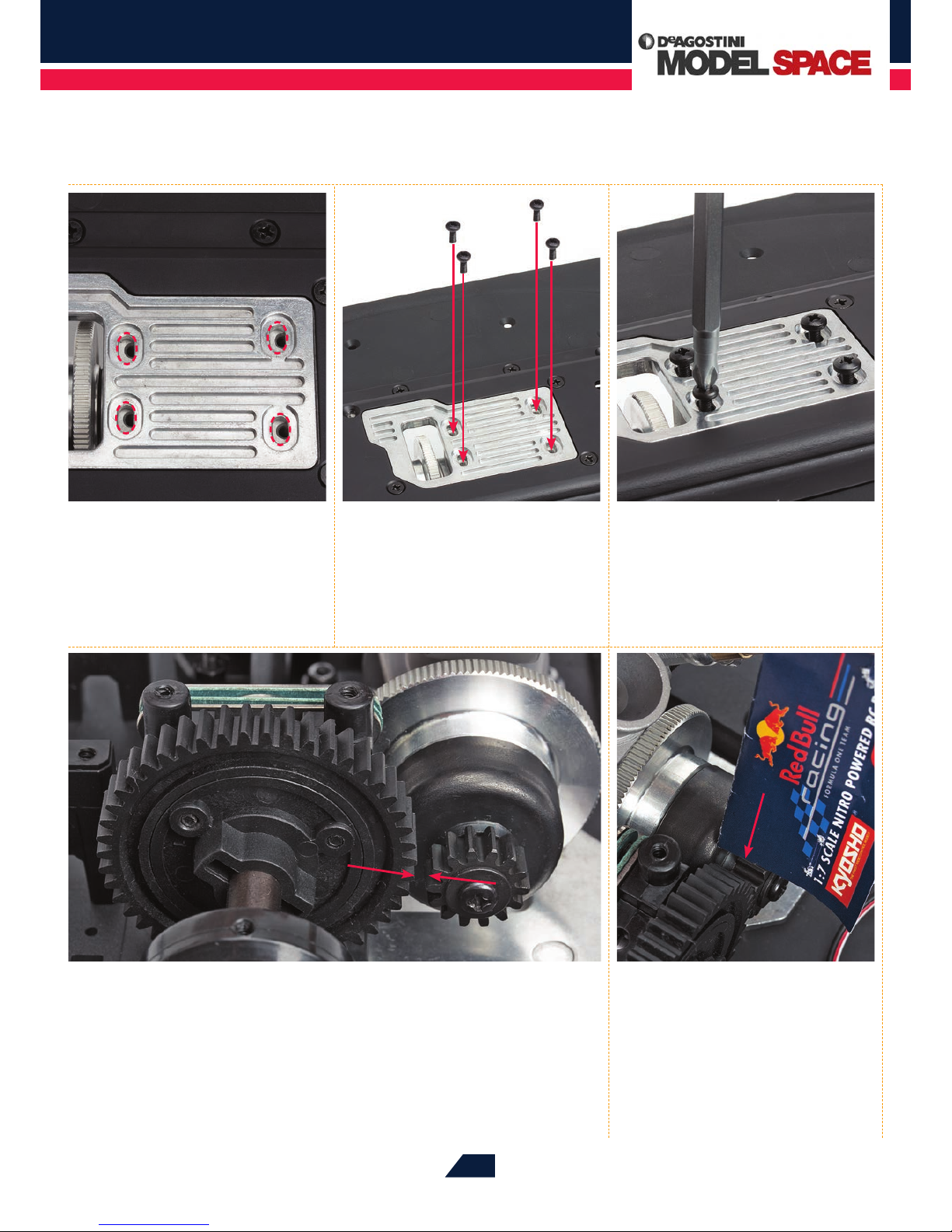
23
Turn the chassis over again and check the positions of the spur and pinion gears.
Adjust the engine’s position so that the two gears are sitting parallel to each other,
with their teeth aligned and ready to be engaged neatly, as shown by the red arrows.
21
Place the four 3 x 8mm dome-
headed screws supplied with this
stage into the four holes marked in the
photo for Step 20 and tighten each one
with your ngertips.
24
Move the gears together as
indicated by the red arrows
in the photo for Step 23, making sure
that the engine’s pinion gear remains
perfectly parallel to the spur gear.
Engage the teeth of the gears and feed a
strip of cardboard in between them (the
cardboard from your RB7’s packaging is
suitable for this).
20
Hold the chassis assembly
together and carefully turn it
over. Gently slide the engine back and
forth until its four screw holes line up
with those of the engine mount (see
dotted red lines).
22
Now tighten each screw a little
further with the screwdriver,
but don’t tighten them fully. The engine
should still be able to slide a little from
side to side.
Page 18
Red Bull Racing RB7: Step by Step
™
387
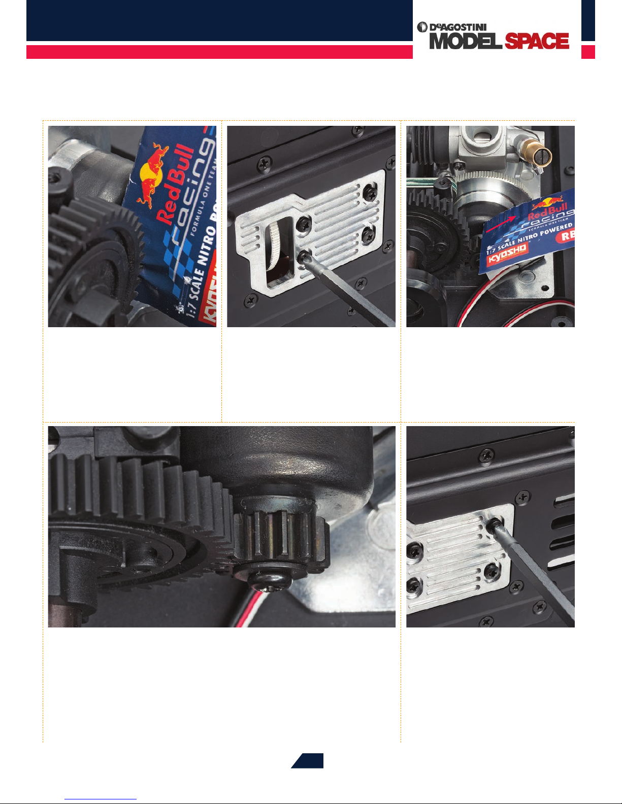
28
Your assembly should now look like this, with the spur gear and the pinion gear
neatly interlocked. Check that the two gears can move without too much resistance
and that the teeth engage smoothly. If the gears are not aligned, or the teeth don’t engage
properly, repeat Steps 24 to 28.
29
When you are sure that the gears
are meshing correctly, carefully
turn the chassis over once more and fully
tighten the dome-headed screws so that
the engine will not move on its mount.
25
Carefully position the gears so that
your assembly looks like this, with
the two gears pinching the cardboard
strip between them. Check again that the
gears are perfectly parallel to each other.
26
Holding the engine carefully in
place, turn the chassis over again
and, using the screwdriver, tighten the four
dome-headed screws until they just begin
to bite. Do not tighten them fully at this
stage.
27
Turn the chassis over again and
check that the gears are still
correctly aligned. If not, repeat Steps 24
to 27 until they are. When the gears are
aligned, pull the cardboard strip out from
between them (red arrow).
Page 19
Red Bull Racing RB7: Step by Step
™
388
1
2
33
Begin tightening the screws
with the screwdriver, using the
red arrows in the photo for Step 32 for
reference. Fully tighten the three screws
marked with solid red arrows, but don’t
fully fasten the two marked with dotted
arrows.
34
Turn the chassis over again,
and re-insert the two screws
removed in Steps 11 and 12. The longer
screw will t into the hole marked ‘1’, and
the shorter one in the hole marked ‘2’.
Tighten both fully with the screwdriver.
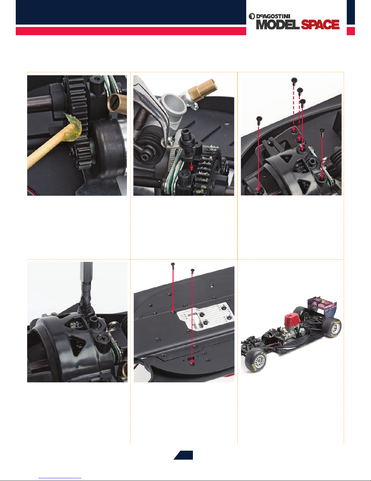
30
To ensure that the gears will
operate smoothly, use a toothpick
to apply a moderate amount of grease
(supplied with Stages 38 and 63) to the
teeth. Then rotate the gears a few times to
spread the grease evenly.
32
Now replace the gearbox cover
removed in Steps 13 and 14, and
put the ve screws that you removed
then back into their respective holes.
31
Take the brake rod and cam that
you removed in Step 15 and
carefully reposition them into the hole
on the rear centre dierential housing
(see red arrow). You may like to use
angled needle-nose pliers to do this.
35
This assembly stage is complete,
and your RB7’s GX21 engine is
now fully assembled and mounted on
the chassis.
Page 20
Red Bull Racing RB7: Step by Step
™
389
THE FIRST TASK IN THIS SESSION IS TO ASSEMBLE THE AIR FILTER AND MOUNT IT
WITHIN THE DRIVER’S HELMET. THEN YOU APPLY THE DETAILING STICKERS TO THE
HELMET AND ATTACH THE COMPLETED ASSEMBLY TO THE ENGINE.
FITTING THE
AIR FILTER
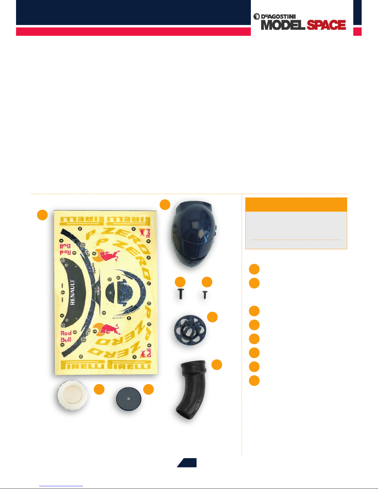
1
2
43
Tools & Materials
1
Sticker sheet
2
Helmet air filter covers
(left and right)
3
Dome-headed screw 2.6 x 8mm
4
Dome-headed screw 2 x 6mm
5
Air filter base
6
Air filter pipe
7
Air filter cap
8
Air filter element
Phillips screwdriver (size 1)
Scissors
Craft knife
5
6
78
Stage 78
Page 21
Red Bull Racing RB7: Step by Step
™
390
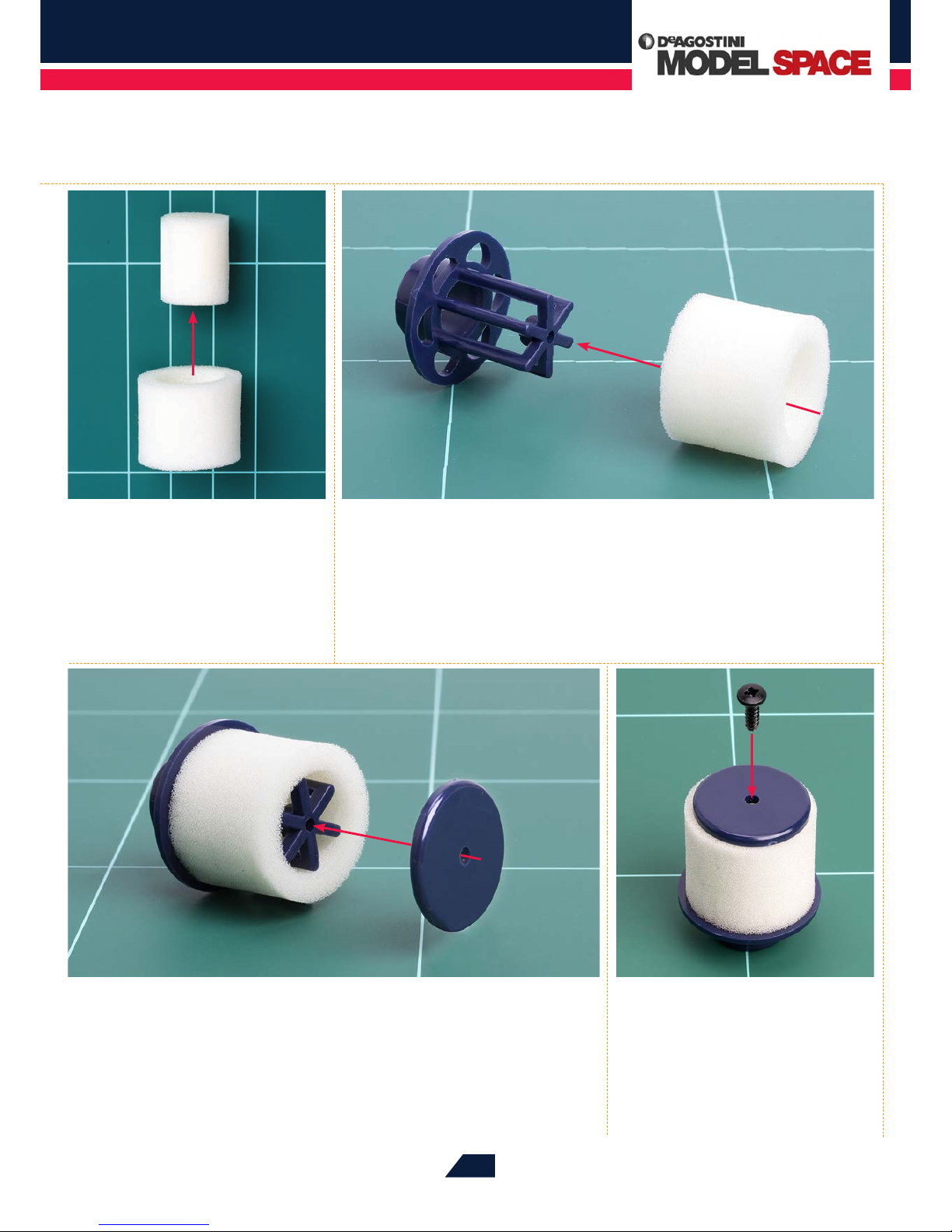
03
Next, t the air lter cap onto the end of the star-shaped projection, aligning the
holes as indicated by the red arrow. Then stand the lter on its base, as shown
in Step 04.
04
With the lter assembly facing
upwards, set the 2.6 x 8mm
dome-headed screw into the central
hole in the cap.
01
Remove and discard the central
section of the air lter element.
02
Though not essential, it‘s a good idea to work some air lter oil into the element
at this stage, as it will make the lter more eective (see page 375). Then push the
element over the star-shaped projection on the air lter base, as shown by the red arrow,
until it butts up against the circular rim.
Page 22
Red Bull Racing RB7: Step by Step
™
391
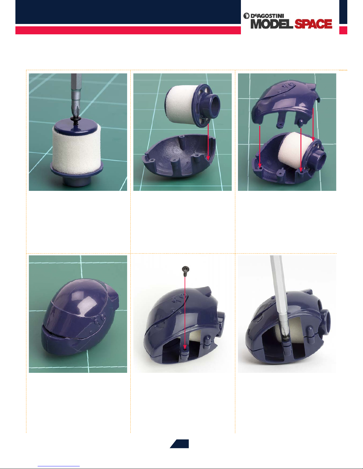
08
Your lter and helmet assembly
should now look like this.
09
Turn the assembly on its side, and
place the 2 x 6mm dome-headed
screw into the arrowed hole on the
underside of the helmet cover.
10
Tighten the screw using a
screwdriver, making sure not to
overtighten it as this could damage the
plastic part.
05
Tighten the screw fully with a
screwdriver.
06
Lay the left side of the helmet
air lter cover on your work
surface, as shown. Then lower the air
lter assembly onto it so that the ridge
around the edge of the lter base sits
neatly into the groove at the rear of the
helmet cover (see red arrow).
07
Next, join the right side of the
air lter cover to the left. Fit the
groove at its rear over the ridge on the
air lter base, and its locating pins into
the corresponding holes (see arrows).
Page 23
Red Bull Racing RB7: Step by Step
™
392
14
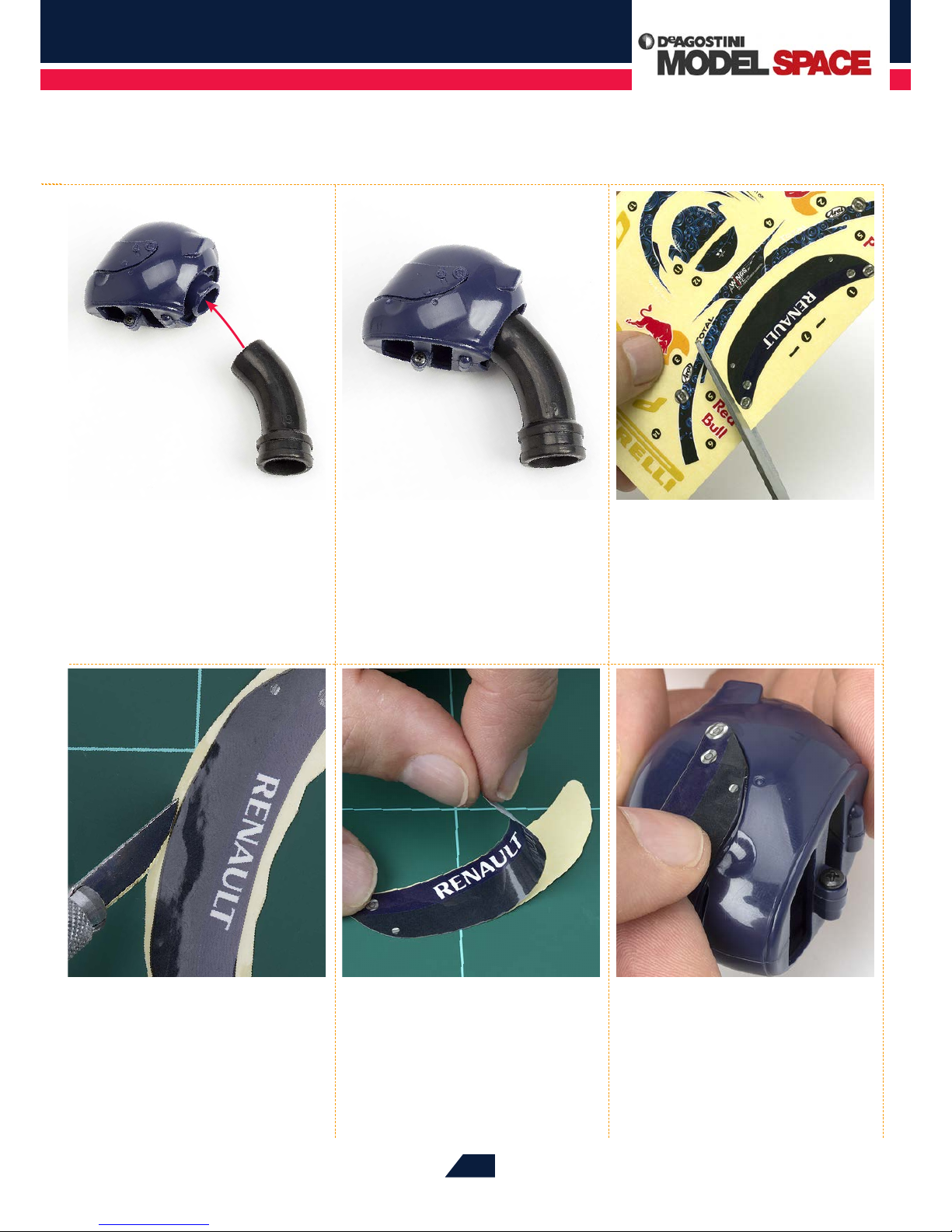
Next, place the sticker on a
cutting mat and use a craft knife
to carefully trim down the excess, so
that you are left with the RENAULT
sticker alone.
15
Carefully remove the sticker from
its backing sheet.
11
Next, t the narrower end of
the air lter pipe over the base
of the air lter.
12
Your assembly should now look
like this.
16
Place the sticker onto the visor
section of the helmet cover and
press it into place. Do this gradually from
one side to the other, so that no creases or
air bubbles form. You may nd it easier to
remove the air lter pipe tted in Step 11
while you apply the stickers.
13
Very carefully cut out sticker 1
from the sheet, using scissors.
Make sure that you don‘t cut into any of
the other stickers as you do this.
Page 24
Red Bull Racing RB7: Step by Step
™
393
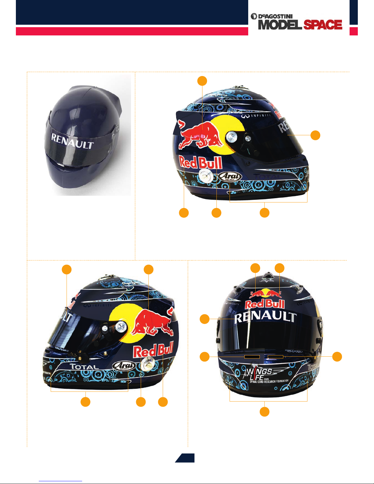
1
65
3
19
Do the same for stickers 2 and 4-6 to the left side of the
helmet.
5 6
2
1
20
The photo above shows the locations of stickers 7-9. Apply
these as you did for the other stickers, again making sure
no air bubbles or creases occur.
8 9
1
7
7
4
4
17
Your assembly should look like
this from the front.
18
Repeat the process described in Steps 13 to 17 to apply the stickers numbered
3-6, as shown above, to the right side of the helmet cover. Again, apply the
stickers very carefully to ensure no air bubbles or creases occur.
4
Page 25
Red Bull Racing RB7: Step by Step
™
394
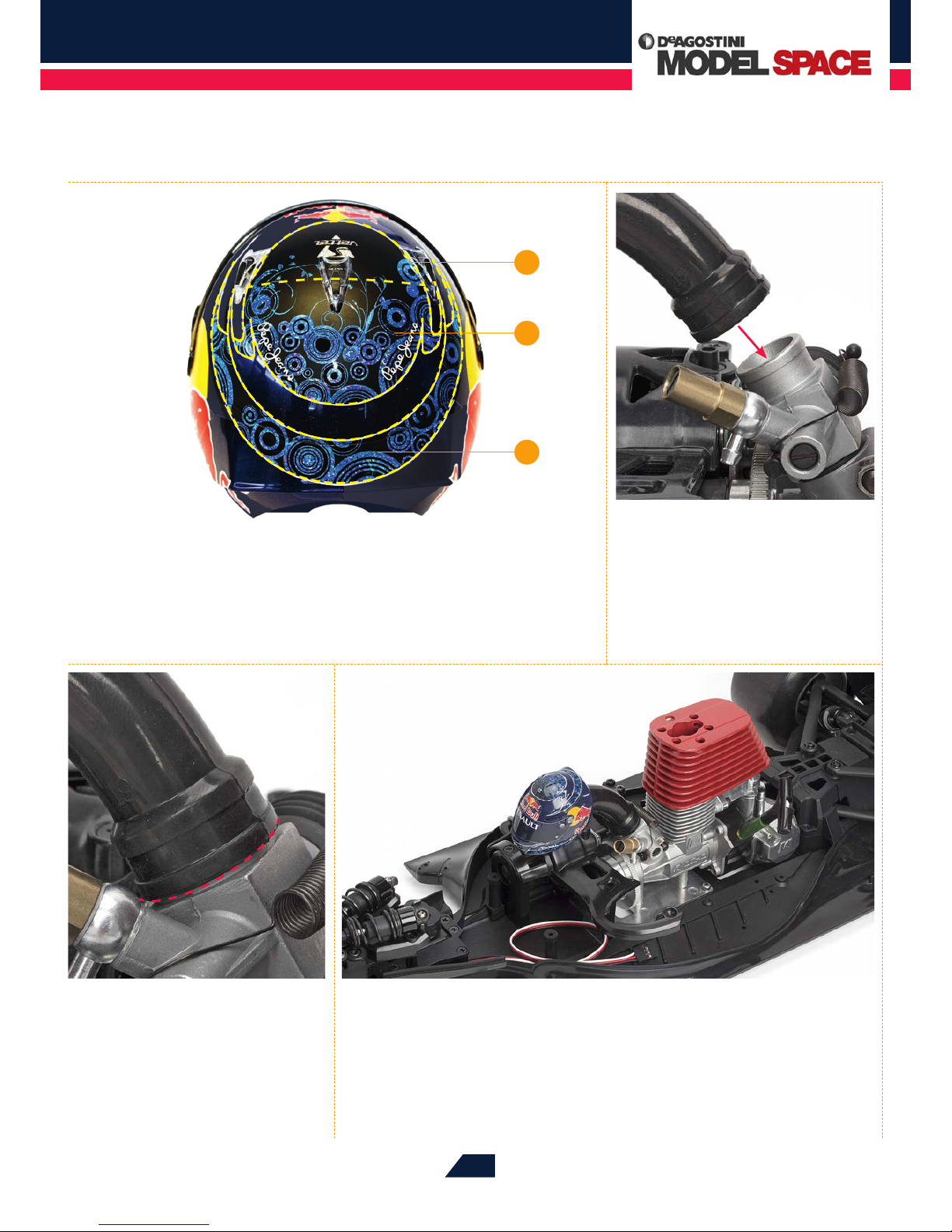
23
Push the air lter pipe as far as
it will go, so that its mouth rests
against the metal of the carburettor (red
dotted line).
24
This stage is complete. Store your parts away securely until next time. The
remaining stickers on the sheet will be applied to the inside rim of the
tyre, so keep these safely until they are needed.
10
12
11
21
Finally, apply stickers 10-12 to the top surface of the helmet cover. Use the yellow
dotted lines shown in the photo above for guidance.
22
If you removed the air lter pipe
in Step 16, re-insert it before
proceeding. Press the wider end of the
pipe over the open intake port of the
carburettor (see red arrow).
Page 26
Red Bull Racing RB7: Step by Step
™
395
IN THIS SESSION, YOU WILL ATTACH THE RC POWER SWITCH TO YOUR
RB7’S RIGHT CHASSIS PLATE.
FITTING THE RC
POWER SWITCH
Phillips screwdriver (size 1)
Tools & Materials
1
RC power switch
1
Stage 79
Page 27
Red Bull Racing RB7: Step by Step
™
396
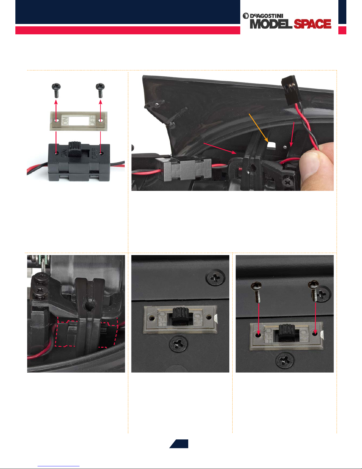
03
Viewed from the side, the switch
(outlined in dotted red lines)
should be positioned as shown.
02
Put the switch onto the right chassis plate, with the cable with the black plug
leading towards the rear of the chassis and the ON/OFF slider facing down. Run the
cable as shown, between the right-hand side of the gearbox cover and the front throttle
servo mount, as indicated by the red arrows. The switch’s slider ts into the rectangular cutout in the chassis plate (orange arrow).
01
Remove the two screws at the
top of the switch, then take o
the ON/OFF cover plate.
05
To complete this assembly stage,
place the two screws that you
removed in Step 01 into the holes in the
cover plate, and tighten them into the
switch to x it in place.
04
Place the cover plate over the
switch’s slider on the bottom of
the chassis plate, as shown. Note: the
OFF side must be sitting in its position
towards the front of the model.
Page 28
Red Bull Racing RB7: Step by Step
™
397
IN THIS SESSION, YOU WILL ATTACH THE BATTERY BOX TO THE SWITCH FITTED IN
THE PREVIOUS STAGE, THEN CONTINUE APPLYING STICKERS TO THE TYRES (IF THE
MODEL IS BEING USED PRIMARILY AS A DISPLAY PIECE).
THE BATTERY BOX
AND ANTENNA TUBE
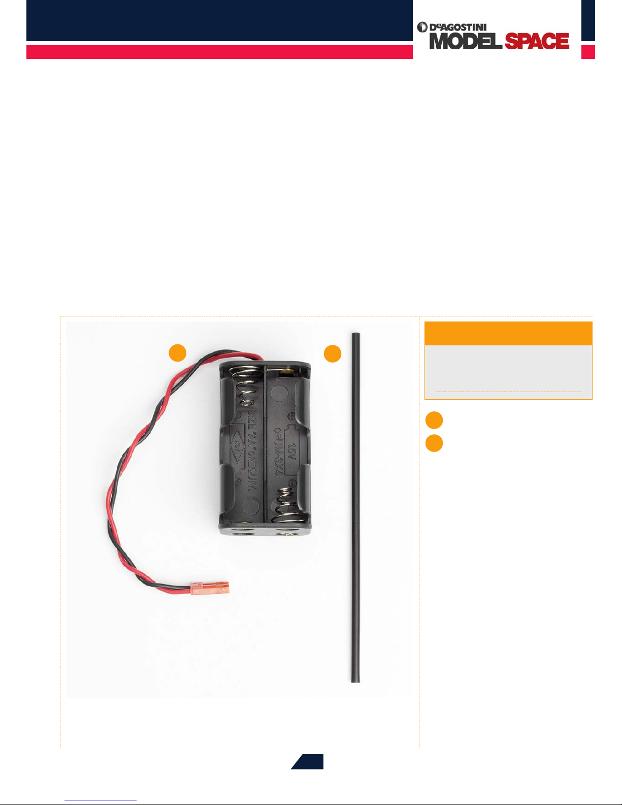
1
2
Cross wrench
Craft knife
Scissors
Tools & Materials
1
Battery box
2
Antenna tube
Stage 80
Page 29
Red Bull Racing RB7: Step by Step
™
398
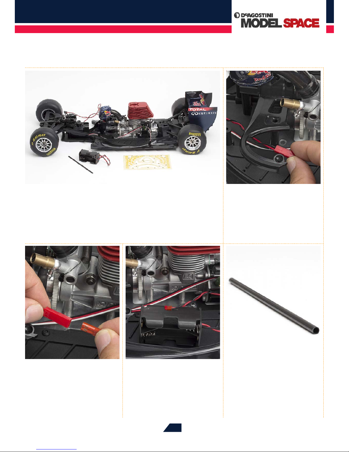
03
Join the red connector from Step 02
into the corresponding one at the
end of the battery box‘s cable. It will only t
in one way.
04
When the cables are connected,
place the battery box on the left
side of the chassis.
05
That completes this phase of
the assembly. Store the antenna
tube away safely until it is needed, and if
you are building your RB7 to be primarily
a display model, continue with the
following steps to apply stickers to your
RB7’s tyres.
01
Lay the parts supplied with this stage out on your work surface. If you are building
this model to be primarily a display piece, keep the sticker sheet supplied with
Stage 78 to hand, as you will be using these to decorate the inside edges of the tyres.
However, you may prefer to skip this phase if you are intending to run your model as an RC
racer, as active use is likely to cause these stickers to peel away. The antenna tube will be
tted at a later stage, so keep this safely until then.
02
First, feed the cable coming from
the front of the switch by the red
connector through to the left side of the
chassis, underneath the arc of the centre
upper plate, as shown.
Page 30
Red Bull Racing RB7: Step by Step
™
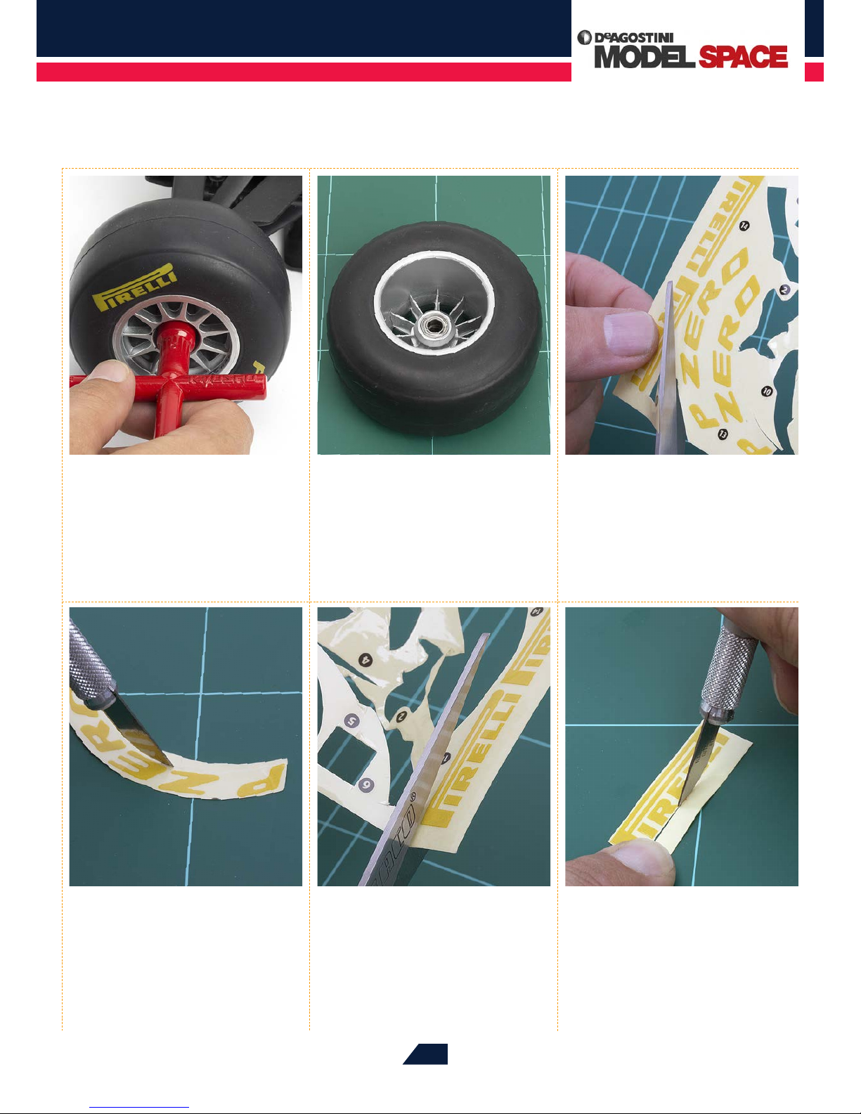
399
09
Lay the sticker out on a cutting
mat and very carefully trim any
excess away from the lettering using a
craft knife. Go as close to the lettering as
you can.
10
Next, cut out the rst straight
PIRELLI sticker from the sheet
using scissors.
11
As you did for Step 9, trim the
excess from the sticker using the
craft knife.
06
If you are choosing to apply the
stickers to the tyres, begin by
removing the front left wheel and tyre by
loosening the wheel nut with the
cross wrench.
07
Rest the wheel on your work
surface with the inner edge
facing up.
08
Carefully cut out the rst curved
P ZERO sticker from the sticker
sheet supplied with Stage 78.
Page 31
Red Bull Racing RB7: Step by Step
™
400
15
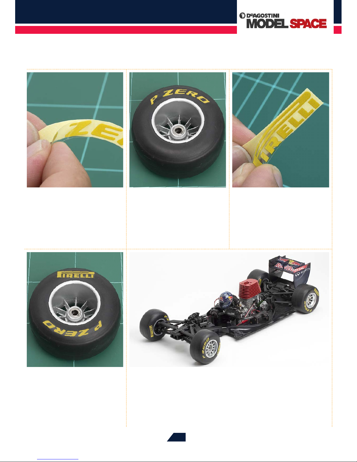
Apply this sticker to the tyre,
directly opposite the P ZERO one.
12
Carefully remove the rst P ZERO
sticker from its backing, trying
to touch it as little as possible with
your ngers.
13
Apply the P ZERO sticker to the
inside edge of the tyre, as shown.
14
As you did for Step 12, carefully
remove the PIRELLI sticker from
its yellow backing.
16
To complete this session, repeat Steps 06-15 to decorate all four tyres with the P
ZERO and PIRELLI stickers, then use the cross wrench to re-attach each wheel to
your model.
Page 32
Red Bull Racing RB7: Step by Step
™
401
™
 Loading...