

Deagostini Model Space HUMMER H1 User Manual
HUMMER H1: STEP BY STEP
™
205
Stage 45
The battery box and power
switch – an overview
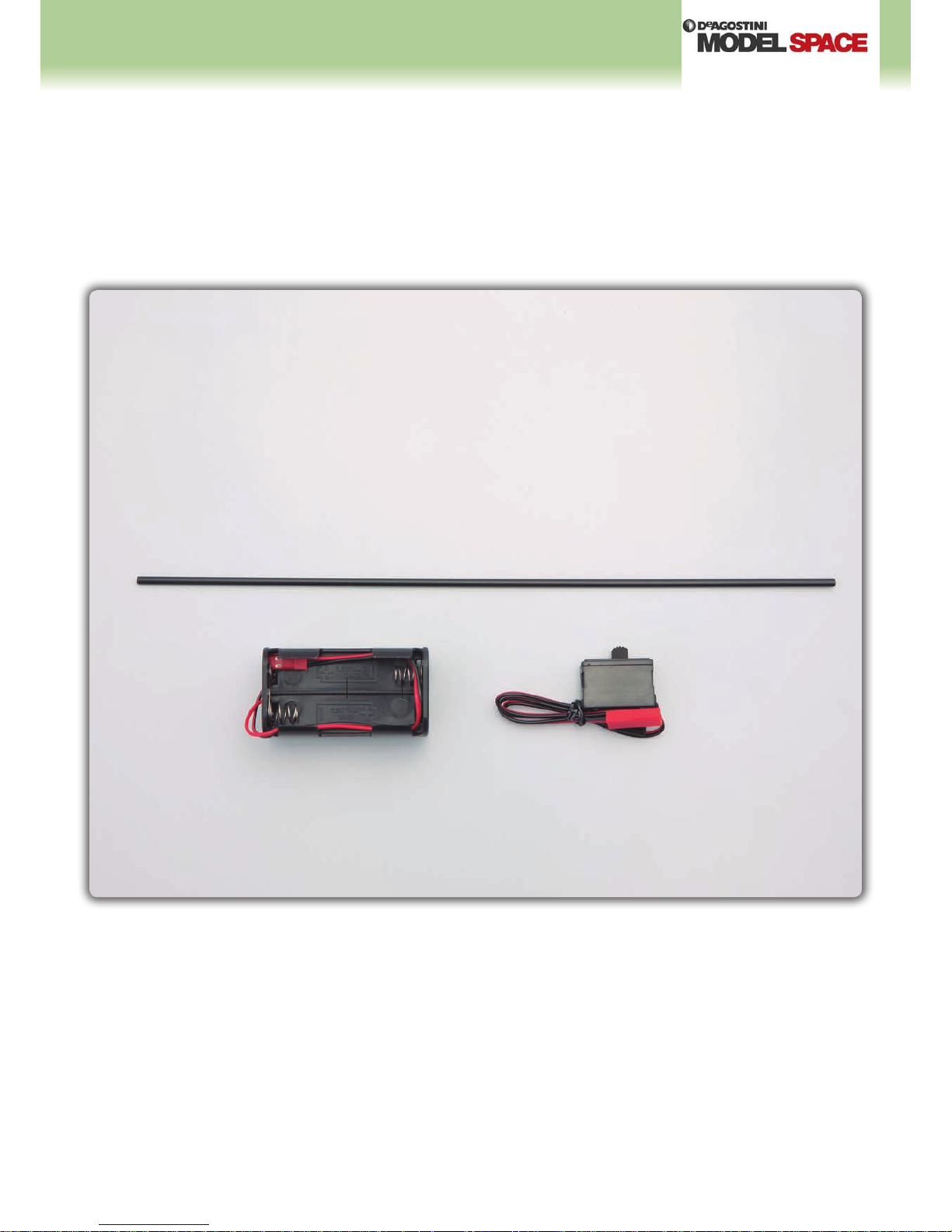
Your parts
Aerial tube
Battery box
Power switch
HUMMER H1: STEP BY STEP
™
206
11
11
33
44
22
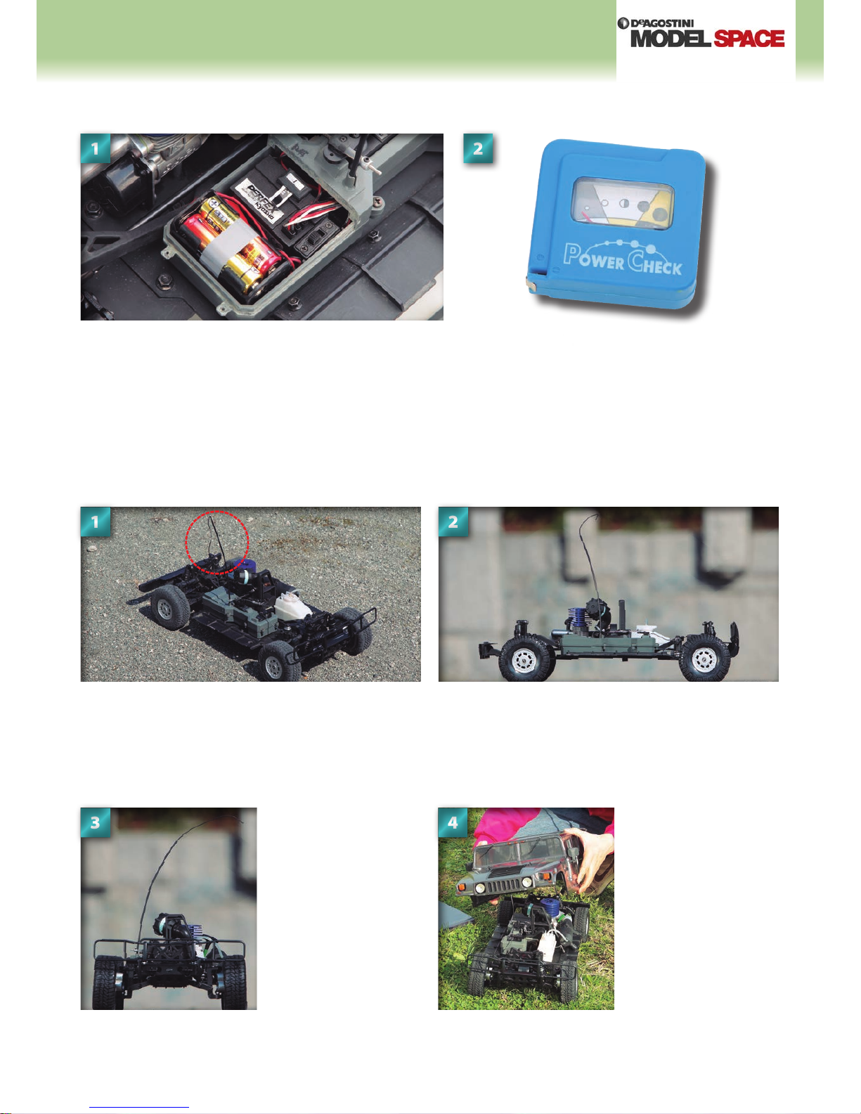
The battery box and power switch is located inside the radio box, which
will be tted to the base of the chassis in coming stages. The box is
pictured open here, but during operation is sealed shut using body pins.
This is to prevent dust and dirt getting inside the components, which can
aect the operation of the parts.
This is the aerial, pictured in its position in the centre of the chassis
with the body frame and panels removed. The length of the wire
will be cut depending on the radio frequency used by the remote
control, but should not be so long that it is folded up, as this will
disturb the signal.
From the front, you can get
an idea of how the aerial
will reach up to the roof
and curve over. This means
that, unlike most RC cars, it
isn’t necessary to cut a hole
in the roof for the aerial.
Fitting the body frame and
panels is straightforward.
Simply lower over the chassis
and aerial carefully, then clip
into place with pins, ready for
action.
Whatever length the aerial is cut to, it will be taller than the roof of
the body panels. This is not an issue, as the soft resin tubing of the
aerial will bend suciently to t inside the body.
The power switch and battery box
The aerial
22
The power supply in your Hummer H1 uses alkaline AA
batteries. It is useful to acquire a battery power checker like the
one in the photo above, to check the power level before tting
replacement batteries.
HUMMER H1: STEP BY STEP
™
207
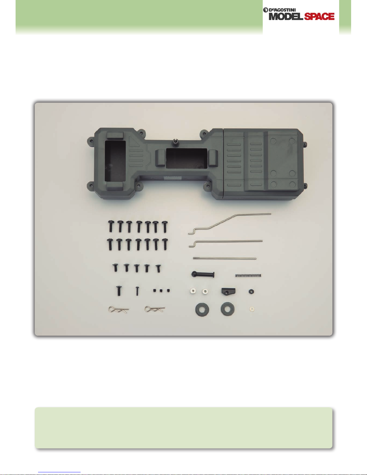
Radio box upper and lower (temporarily assembled)
Radio box lid (temporarily assembled)
3 × 10mm binding-head self-tapping screws × 14
3 × 8mm self-tapping screws × 5
3 × 10mm self-tapping screw
2 × 8mm self-tapping screw
3 × 3mm set screws x 3
Body pins × 2
Steering rod
Brake rod
Throttle linkage rod
Throttle ball end
Throttle spring
2mm stoppers × 2
Linkage base
Brake collar
Radio box collars × 2
2mm washer
Mounting the radio box
Your parts
Tools and
materials
Phillips screwdriver
Main chassis assembly (Stage 44)
Pen
Plastic bag
Stage 46
HUMMER H1: STEP BY STEP
™
208
221144
33
66
55
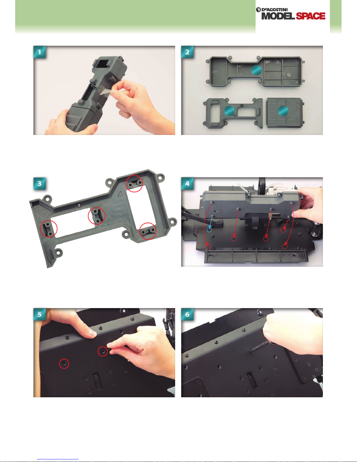
Lay out the parts and make a note of which is which. To the
bottom left (1) is the box upper, at the top is the box lower (2)
and to the bottom right (3) is the lid. Also make a note of their
orientation, as this is the position in which they will be tted
onto the chassis.
Remove the cellophane tape holding together the parts that
make up the radio box.
Line up the radio box lower with the six holes circled on the
surface of the chassis. The hole circled in blue marks the hole
through which you will t the 3 × 10mm self-tapping screw.
Inspect the underside of the radio box upper. There are four sets
of screw holes lining the rectangular openings. These will be
used in the coming steps.
Tighten the screw with a screwdriver.When the projections on the underside of the radio box are
lined up with the six holes circled in Step 4, begin inserting
the 3 × 8mm self-tapping screws, starting with the two central
holes circled above. Place the screw into the hole nearest the
front rst.
Front
Back
1
2
3
HUMMER H1: STEP BY STEP
™
209
778899
Next, t and tighten the second 3 × 8mm
self-tapping screw into the adjacent hole.
Place the 3 × 10mm self-tapping screw into
the hole that sits on the joint between the
chassis’s main and rear plates. This was the
hole marked in blue in Step 4.
Fit the remaining 3 × 8mm self-tapping
screws into the last three holes that were
marked in Step 4. Tighten each fully with
a screwdriver.
This stage is complete. Be sure to keep all
the unused parts in a plastic bag safely,
marked for reference.
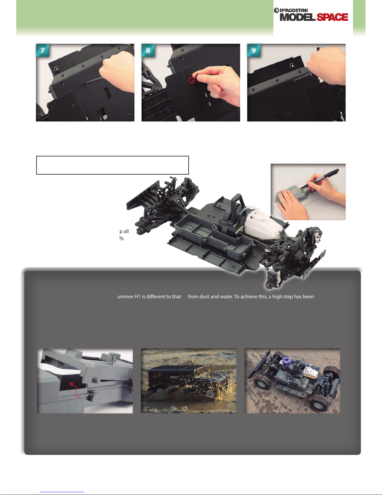
Sealing the radio box
The radio box tted inside your RC Hummer H1 is dierent to that
of most radio-controlled cars. Due the heavier, o-road nature
of its use, your Hummer’s radio box requires a considerable
amount of protection. As such , the radio box is designed and
tted in such a way that it is able to operate under even the
most ambitious driver. Firstly, the radio box itself is made of thick
impact-resistant plastic, moulded to provide excellent protection
from dust and water. To achieve this, a high step has been
moulded along the edges of the upper and lower box sections
(see photo below left). Then, the box is tted several millimetres
above the chassis base, rather than on it, so that the box receives
fewer of the vibrations or jolts experienced by the rest of the
chassis, as these can aect the smooth running of the radio
control components within the box.
The joint between the edges of the radio
box’s upper and lower sections features
a high step to prevent dust particles or
water entering.
It is possible to run your Hummer H1
through puddles, as the crucial radio box
is so well sealed and protected.
The chassis and components stripped
of the body casing after driving through
water. It is advised that the model be
cleaned thoroughly after use.
Assembled parts
HUMMER H1: STEP BY STEP
™
210
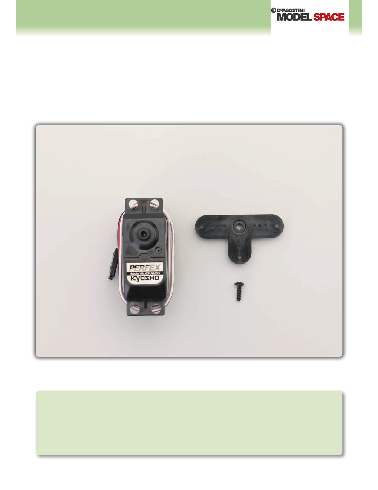
Steering servo (KS-302DS)
Servo horn
2.6 × 10mm servo horn screw
Installing the steering servo
Your parts
Tools and
materials
Philllips screwdriver
Needle-nose pliers
1.5mm Allen key (Stage 11)
Main chassis assembly (Stage 46)
Radio box (Stage 46)
Steering rod (Stage 46)
3 × 10mm self-tapping screws × 4 (Stage 46)
3 × 3mm set screw (Stage 46)
Paper towel or tissue
Thread-locking agent (or rubber-based adhesive)
Stage 47
 Loading...