

Page 1
TECHNICAL MANUAL
KIT DDS WLG VER 6.27
By PU4WLG
This manual details the installation on a radio Cobra 148 GTL Transceiver, but there is nothing to prevent adaptations
on other radio models.
Brief history about this system:
It started as a hobby. In 2015, I, PU4WLG, and a friend, PU4ADD, were talking about Arduino and RF generators, my friend
found the SI5351 module at Ebay and bought 2 for us to test.
One day, we went to a junkyard known to radio amateurs here in Minas Gerais (Brazil) and my friend PU4ADD showed me
an old TELEFUNKEN RTH-220 radio transceiver and told me that it would be possible to put the module we bought on
Ebay and make a racing band system. I bought the radio and with the help of my friend PU4ADD, who has a lot of
knowledge in RF, I took the tests practicing my hobby, because programming Arduino was already the easiest for me. So
my friend showed me where to put the generator in TELEFUNKEN, he also told me what frequency should I generate to
be in LSB and what frequency should I generate to be in USB, with this information I wrote a software to control the
SI5351 and using a 16x4 display I made the modification on the transceiver. Search for Telefunken dds on YouTube and
see the modification. After testing on another radio, I was asked if it would be possible to make this modification on a
Cobra 148 GTL. For this, I purchased a Cobra 148 GTL, made a modification using SI5351 and SSD1306 display and to my
amazement, many people who saw it were delighted with the modification. At the intention of receiving 40 meters in this
project, I asked for help to another friend, PY2SFY, who showed me how to use a BF982 with the configuration of a mixer,
observing the can converter that was exactly like the configuration presented by PY2SFY, so I saw that it would be
complete conversion is possible, not just 40 meters. I was suggested to make a KIT for sale. For this reason you are
reading this manual. Thank you.
Thanks:
I would also like to express my thanks to those who never stopped testing and helping to publicize this system, many
thanks to everyone who always pointed out the errors in the project and so contributed to the improvement of the
system, which is always being improved.
Thank you all.
1
Page 2

Description:
The DDS KIT now comes with polyphonic beeps, SPECTRUM RF scan and AUTO-SCAN.
A firmware with a free version is available for download at the link www.kitdds.blogspot.com
The free version has a time opening screen with countdown, after going through this opening screen the system is fully
functional, limited only to changing the user name and number of channels. To remove the opening screen, a key is
required. I provide the key to remove the splash screen and complete the system release at a small cost.
The KIT DDS WLG VER 6.27 system has the following features:
- User menu for selecting the modes: Channel, Bandwidth, Receiver Radio, Settings Menu.
- Channel mode with frequency meter or user name.
- Channel mode can be adjusted with a maximum limit of 500 positive channels and 500 negative channels.
- Displays the AM / USB / LSB modulation switch position.
- Unification or non-unification of tuning for channel mode.
- Channels change 1 in 1 or 10 in 10 channels.
- For Channel mode, it has 20 polyphonic beeps and a beep draw mode.
- Running Band mode with display of the position of the modulation key, user name and operating status.
- Running Band mode can be adjusted with a minimum limit of 0Hz to 99MHz.
- Operation status displays indication for reception, transmission, beep and failure of the PTT key.
- Has Step in steps from 10Hz to 1MHz.
- It has signal and RF spectrum scanning mode and also an auto-scan function.
- For Band Running mode, it has 20 polyphonic beeps and a beep draw mode.
- Receiver Radio mode with display of the modulation switch position, user name and operating status.
- Radio Receiver mode can be adjusted with a minimum limit of 0Hz to 99MHz
- Operation status indicates transmission reception and cut-off.
- Has Step in steps from 10Hz up to 1MHz.
- It has signal and RF spectrum scanning mode and also an auto-scan function.
- Transverter mode with display of the modulation switch position, user name and operation status.
- Transverter mode can be adjusted to display frequency reference for any HF transverter.
- Operation status displays indication for reception, transmission, beep and failure of the PTT key.
- Has Step in steps from 10Hz up to 1MHz.
- For the transverter mode, it has 20 polyphonic beeps and a beep draw mode.
- User menu with 4 shortcut screens to access the system's operating modes.
- Settings menu allows up to 9 simple adjustments for end users or 29 adjustments for technicians.
- The end user can adjust 9 items: (1) User name, (2) Beeps, (3) Adjust the interval between PTT and BIP, (4) Anatel table,
(5) Channel mode frequency on / off, (6) Unify / Disunify Voice Lock tuning in transmission mode, (7) Control screen
brightness, (8) Transmission time limit, (9) Align Transverter.
- Installer technician can adjust all items of the end user and also: (10) Check SI5351 module reference crystal, (11) Check
the RF amplitudes of the SI5351 module driver, (12) Define the internal capacitors for the SI5351 reference, (13) Generate
2
Page 3

any frequency between 400KHz up to 99MHz at the CLK1 output of SI5351, (14) Set OFFSET to FI in RX, (15) Set OFFSET to
FI in TX, (16) Set OFFSET AM, (17) Set OFFSET LSB, (18) Set OFFSET USB, (19) Determine the maximum frequency for
Bandwidth mode, (20) Determine the minimum frequency for Bandwidth mode, (21) Determine the maximum of positive
channels, (22) Determine the maximum number of negative channels, (23) Set a frequency to activate a filter for lower
frequencies, (24) Adjust Voice Lock width, (25) Set conversion frequency for Radio Receiver mode, (26) Determine the
maximum frequency for Radio Receiver mode, (27) Determine the minimum frequency for Radio Receiver mode, (28)
Choose between 2 encoder models, (29) Reverse the direction of the selector switch.
3
Page 4

CONTENTS
DDS System Description .............................................. ................................................... ........................... 02
System operating modes ............................................. .......................................................... ................... 05
How to use the encoder switch button ........................................... .................................................. ........ 05
Using the system in channel mode ............................................ ................................................... ............. 05
Using the system in running band mode (VFO) ........................................ .................................................. 05
How to use the Spectrum and AUTO-SCAN scan function ............................................ ............................. 06
How to configure the system just for running band mode (VFO) .......................................... .................... 06
How to remove Channel mode ............................................. .............................................. ...................... 06
How to remove Receiver Radio mode ............................................ .................................................. ........ 06
Understanding and using the Settings Menu (Service menu) ......................................... .......................... 07
Settings menu items (Service menu) ........................................ ............................................................ .... 08
Detailed Arduino pinout .............................................. ............................................................................. 10
Circuit diagram. .................................................. ...................................................................................... 11
Arduino Module Power .............................................. ............................................................................. 11
Display Power ............................................... .................................................. ....................................... 12
Feeding and alignment of Module SI5351 ............................................ .................................................. 12
Clarifying Potentiometer (Voice Lock) ............................................ .................................................. ......14
Configuring encoders ................................................ .................................................. ........................... 15
Modulation switch AM, FM, CW, USB, LSB ...................................... .................................................. ..... 16
PTT sensor ............................................... .................................................. ............................................. 17
BIP circuit (Speaker cut and carrier arm) ................................................................................................ 18
BIP audio output ..................................................................................................................................... 20
Installing spectrum sensor and auto-scan ................................................................................................20
Filter for negative channels ..................................................................................................................... 21
Making the conversion plate for RX HF ....................................................................................................21
Using the Transverter mode .................................................................................................................... 23
Installing DDS on a Radio Cobra 148 GTL ................................................................................................ 23
Aligning L19 and L20 ................................................................................................................................ 33
Problems and solutions ............................................................................................ ............................... 34
4
Page 5
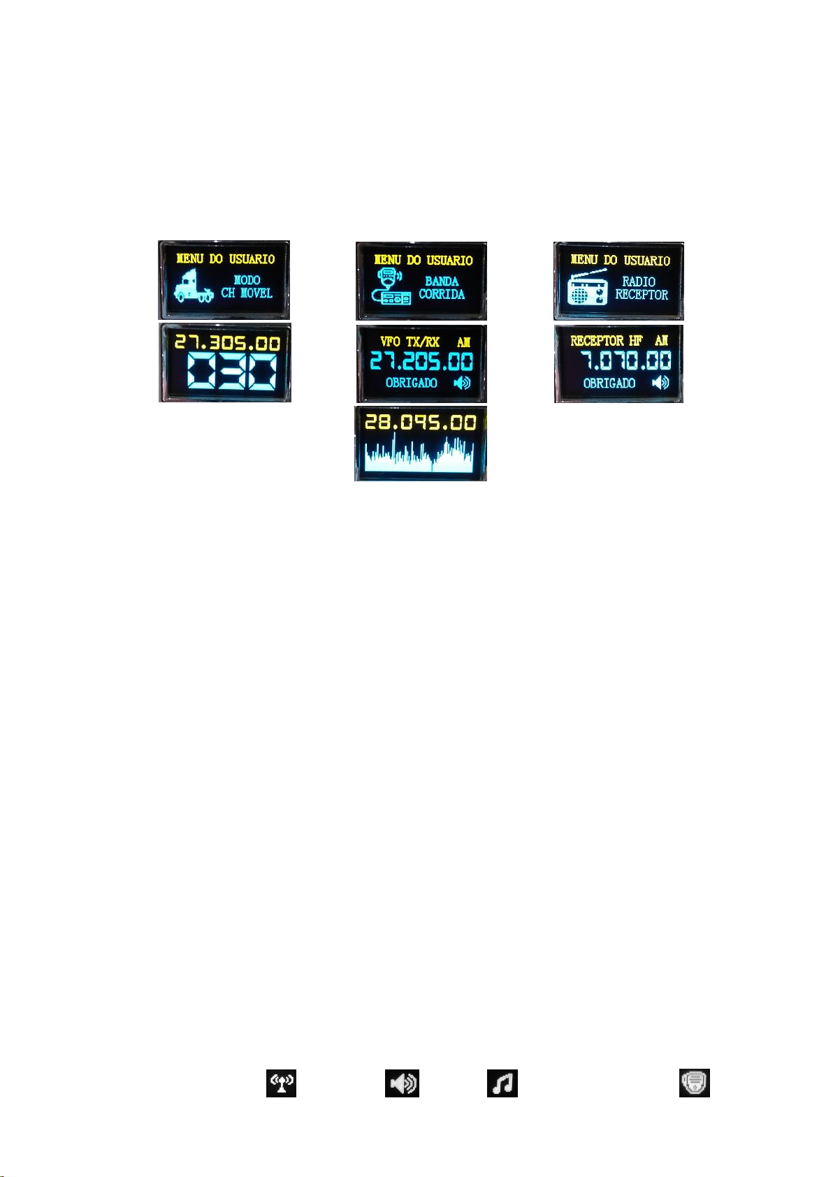
System operating modes.
The DDS WLG 6.27 system has 3 operating modes that can be selected through a user menu, it also has a transverter
mode that requires a switch to be activated. The 3 modes of the user menu allow to operate the radio as the traditional
channel mode or the bandwidth mode or VFO mode, and if you have installed a converter card, you can also have the
RECEIVER HF mode.
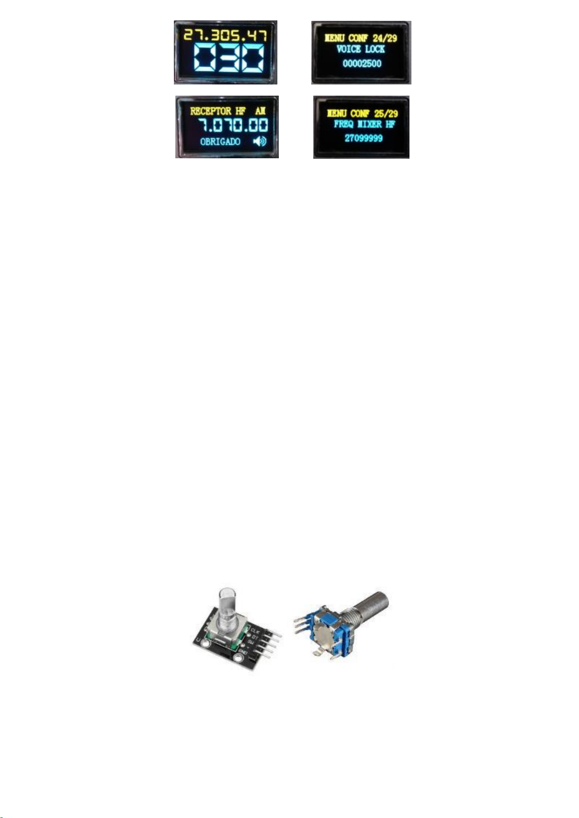
These photos are from each operating mode (in portuguese language).
The channel mode allows you to operate the radio by changing the channels using the encoder switch, displaying the
channel frequency and allows you some features, such as the step to jump 1 in 1 channel or jump 10 in 10 channels and
also has an automatic return to 1 in 1 channel after 5 seconds of inactivity. It is tuned by the VOICE LOCK clarifying
potentiometer, which can be in unified or unified tuning, depending on the setting made in the menu. You can also
remove the frequency meter and display the name or area code instead. (If you did not want to have the channel mode,
the technician can leave item 21 in the settings menu to zero.)
How to use the system in channel mode:
The first step is to understand how to use the encoder switch button.
We will understand the button as option 1, 2 and 3 of the encoder switch button.
Option 1 (Short press, less than 1 second pressed.)
Option 2 (Middle touch, more than 1 second and less than 3 seconds pressed.)
Option 3 (Long press, pressing and holding.)
To enter Channel mode, use option 2 on the button and the system will enter the user menu. When in the user menu,
rotate the encoder to the CH MOVEL MODE icon. To access this mode, use any of the 3 button options. In channel mode,
change channels by moving the encoder to either side or use option 1 on the button to change the step step. (Note: the
modulation mode will be displayed for 3 seconds in each switch change).
How to use the system in running band mode:
To enter running band mode, use option 2 on the button and the system will enter the user menu. When in the user
menu, rotate the encoder to the RUNNING BAND icon. Change the frequency by turning the encoder in any direction, use
option 1 on the button to change the steps in the step. Note that the running band mode has a status of using PTT. This
status will indicate that the radio is transmitting, receiving, beeping or has occurred PTT failure. In
5
Page 6
case of impossibility of transmission, for example, overflow of the time limit allowed for transmission (item 8 of the
settings menu) the status will show an X indicating that the TX has been interrupted or is inactive.
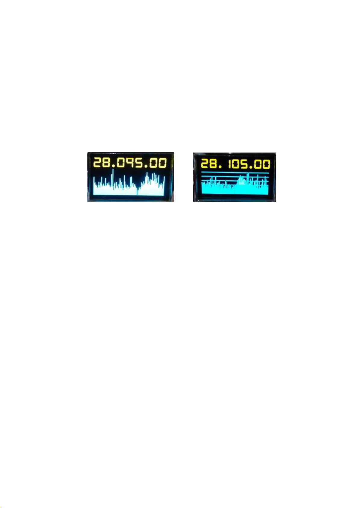
The running band mode allows to operate the radio by changing the frequency using the encoder switch, it has steps of
step from 10Hz up to 1MHz. The RUN BAND mode and RECEIVER RADIO mode are identical in use, with the exception of
TX for the RECEIVER RADIO mode, but both are identical and also have a very useful feature that serves as a spectrum
analyzer, which can eliminate spurious ones. To enter the spectrum analyzer, use option 3 of the encoder switch button.
The system will scan frequencies exactly in the step of the step that was left before starting the spectrum, the spectrum
screen allows an auto-scan option that will search for signals outside the natural pattern of the spectrum, finding a signal
outside the pattern, the system for scanning and remains at that frequency as long as the signal is present, but if the
signal disappears, the system waits for 3.5 seconds and resumes scanning. To activate auto-scan, turn the encoder switch
to the right and horizontal lines will appear on the scan screen. To exit the auto-scan, in case the scan stops at an
unwanted signal, turn the encoder to the left and the auto-scan will be deactivated, to activate it, turn the encoder again
to the right. To exit the scan or auto-scan and return to the previous mode, use option 1 on the button or click on the PTT
button.
The amplitude of the spectrum can be controlled using the RF-GAIN potentiometer. The auto-scan function is perfect to
perform a good alignment of the DDS system, because through it you can check if your radio has a spurious over some
frequency that corresponds to a PX Channel.
Configuring the system just for race band mode (VFO)
Depending on the equipment used, the technician will be able to remove the channel mode, as he performed the
installation on an HF transceiver. In this case, the CH MOVEL MODE icon can be removed from the system simply by
resetting item 21 of the settings menu.
Removing the RECEIVER RADIO mode
The technician may have done a DDS installation where the customer has chosen not to have the HF reception or
RECEIVER RADIO in which case the technician may remove the RECEIVER RADIO mode icon by resetting item 25 in the
settings menu.
SETTINGS MENU overview
NOTE: The SETTINGS MENU icon will appear for the installer, but after grounding the Arduino D12 pin, this icon will be
removed from the user menu and will only appear when the user turns on the radio with the encoder switch button
pressed, even so, the user will only have access to item 9 of the settings menu.
6
Page 7
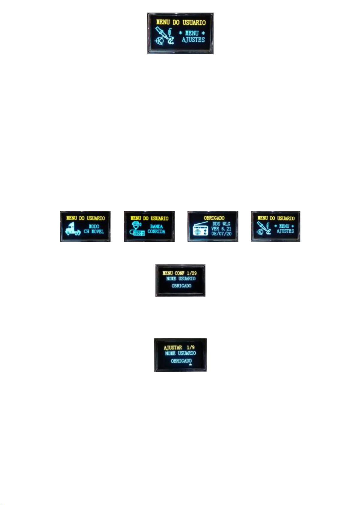
Learning to use the settings menu.
The settings menu, popularly known in the technical field as the service menu, allows a total of 29 adjustments. To access
the settings menu, the DDS WLG system must have a D12 pin free from grounding.
The encoder button has 3 options.
Option 1 Short click (Less than 1 second pressed)
Option 2 Medium click (1 to 2 seconds pressed)
Option 3 Long click (Press and hold)
To access the settings menu, you will enter the user menu using option 2 on the button, entering the user menu you will
select the SETTINGS MENU and use option 2 on the button. (The only icon that accesses only with option 2 on the button
is the settings menu. The rest of the icons can be accessed with option 1, 2 or 3 on the button).
Entering the service menu, the system will display item 1/29
In this item you technician or end user can add a prefix or any word with up to 8 characters. To change the word THANK
YOU, use option 2 on the button and a cursor will appear below the corresponding letter. Also note that the word ADJUST
will appear in place of MENU CONF.
Note that on this screen, we only have 1/9 items, the reason is because this photo was taken on a system with the D12
pin grounded and in this case, the system releases only 9 basic items for the end user, but as you are reading the
technical manual, you will most likely be seeing ADJUST 1/29.
With option 1 of the button, you will change the position of the cursor, to change the letter, turn the encoder switch in
any direction. If you want to change the item, you will use option 2 of the button again, using option 3 anywhere in the
settings menu, the system will exit the settings menu and return to the user menu. Another important detail is that any
changes in the settings menu will only be saved if you leave the settings menu without turning off the system.
Note: All items that allow only 0 or 1, means that 0 is off and 1 is on.
7
Page 8
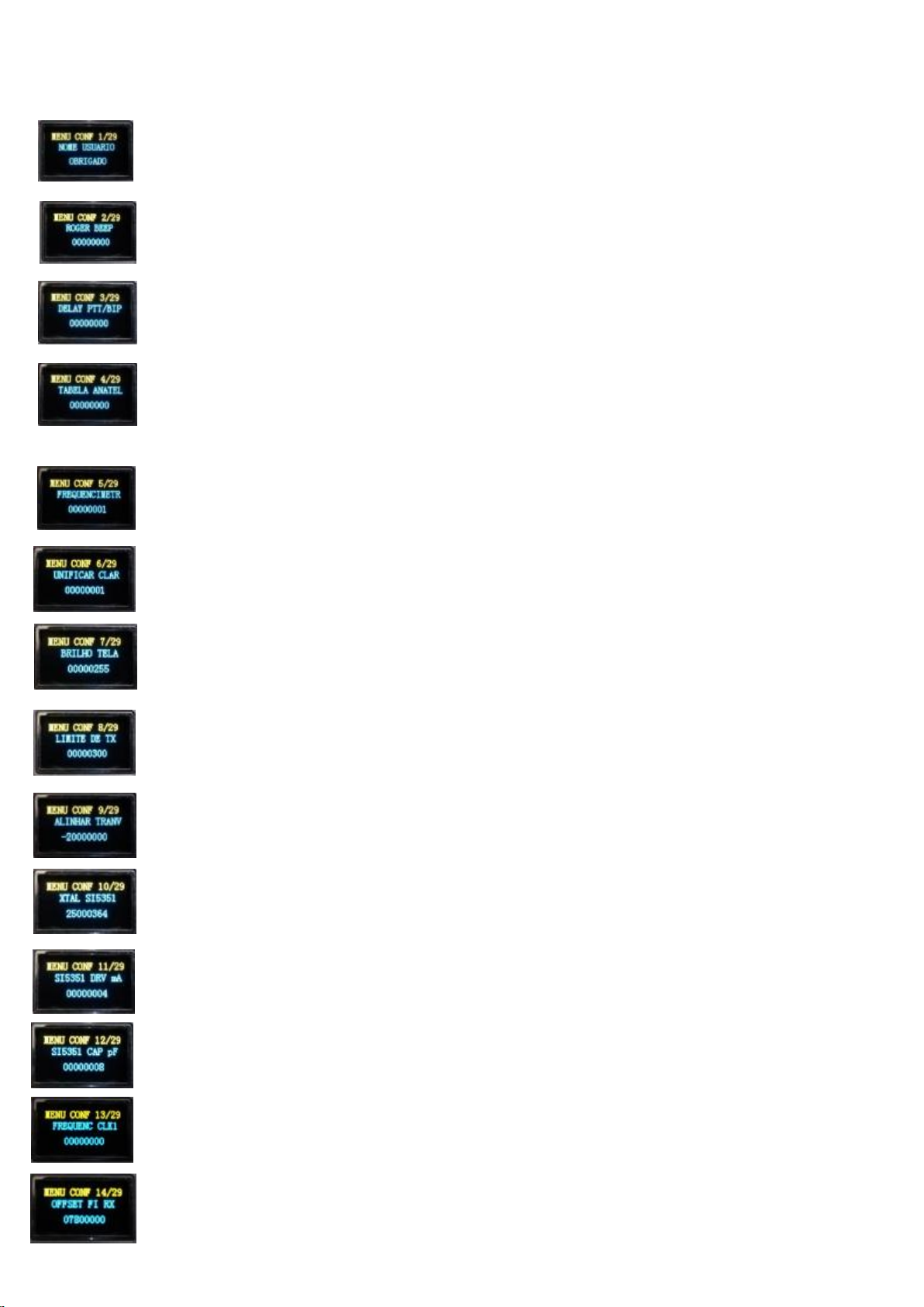
Details of all items service menu.
1- Prefix or user name with up to 8 characters.
2-Beeps selection. Allows you to choose between 20 polyphonic beeps, or you can use the LUCKY option.
3- Time interval between speaker relay and carrier.
(Eliminate popping noise from the speaker)
4-If connected, configure the system according to Anatel's standard (brazilian rules), following the table
from 1 to 80 channels.
5- If it is off, it’ll remove the frequency display in Channel mode and display the call sign.
6- If it is on, it will unify the tuning of the clarifying potentiometer (VOICE LOCK) with TX and RX.
7- Controls the brightness of the screen.
8- Limits the time in seconds that the PTT can keep the carrier active.
9-Removes or adds the value in the VFO in transverter mode. (Display the exact frequency of the
transverter)
10- Tells the system what the frequency of the crystal used in SI5351. (Check DDS on that item).
11- Set output current CLK0, CLK1, CLK2 of module SI5351. (When in doubt, use 4 or 6mA).
12- Adjust internal capacitors for the reference crystal. (When in doubt, use 8pF).
13- It allows generating any frequency between 400KHz up to 99MHz on the CLK1 (only one optional).
14- Intermediate frequency deviation in RX. (OFFSET for when the system is not transmitting). Any
changes to that item will be automatically copied to item 15.
8
Page 9
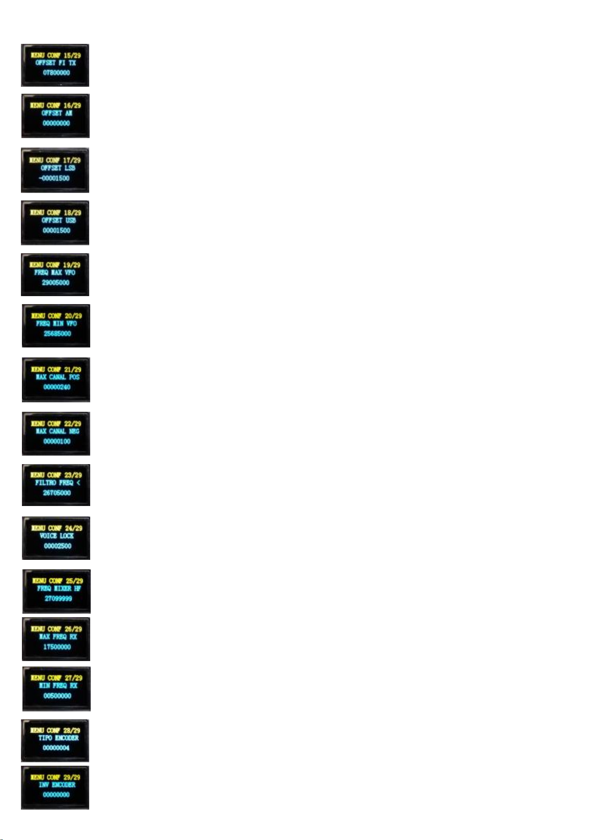
15- Intermediate frequency deviation in TX. (OFFSET for when the system is transmitting).
16- Frequency deviation for AM mode. (OFFSET for when the system is in AM).
17- Frequency deviation for LSB mode. (OFFSET for when the system is in LSB).
18- Frequency deviation for USB mode. (OFFSET for when the system is on USB).
19- Maximum frequency that Band mode can reach. (For Scan, always use 5000 at the end).
20- Minimum frequency that Band mode can reach. (For Scan, always use 5000 at the end).
21- Maximum number of Positive Channels. (If you want to remove Channel mode, leave items 21 and 22
reset)
22- Maximum number of Negative Channels. (If you want to remove Channel mode, leave items 21 and
22 reset)
23- Connect Arduino output A0, while the system is below that frequency.
24- Adjust the clarifier tuning value in Channel mode. (Adjusts the width of the clarifier).
25- Frequency at which the radio remains while using a mixer board for RX HF
By resetting this item, the system will no longer display the RECEIVER RADIO mode icon.
26- Maximum frequency that the Radio Receiver mode can reach.
27- Minimum frequency that the Radio Receiver mode can reach.
28- It allows to use 2 different types of encoder. (The most common is type 4).
29- It allows changing the direction of rotation of the encoder without the need to invert wires.
9
Page 10

Detailed Arduino pinout (KIT DDS VER 6.27)
Pin (VIN) - Voltage input 7V to 9V (Maximum 12V - not recommended).
Pin (VDC) - 5V Stabilized output (you can supply 5V here or use the 5V stabilized).
Pin (5V) - 5V Stabilized output (you can supply 5V here or use the 5V stabilized).
Pin (GND) - Grounding.
Pin (D2) - Direction of the encoder switch (DT or CLK).
Pin (D3) - Direction of the encoder switch (CLK or DT).
Pin (D4) - Encoder switch button (SW).
Pin (D5) - Switching to GND for AM mode.
For LSB mode, do not switch D5 and D6; and for FM mode, switch to GND D5 and D6 together.
Pin (D6) - Switching to GND for USB mode.
Pin (D7) - Switching to GND for CW mode.
Pin (D8) - Audio output for the beep.
Pin (D9) - Output 5V to arm relay that turns on/off loudspeaker (BIP).
Pin (D10) - Output 5V to arm carrier.
Pin (D11) - Switch with GND to display frequency reference of the external converter.
Pin (D12) - Ground this pin to prevent critical changes to the service menu (this is important).
Pin (D13) - Status LED (If it is flashing slowly, it is processing normal).
Pin (A0) - Filter for frequencies below the value defined in item 23 of the service menu.
Pin (A1) - 5V output for activating the switching relay of the converter board.
Pin (A2) - Clarifying potentiometer (Never exceed 5V).
Pin (A3) - PTT sensor. (Be very careful when installing this pin, see details in the diagram).
Pin (A4) - SDA pin used in the i2C communication protocol (Display + SI5351).
Pin (A5) - SCL pin used in the i2C communication protocol (Display + SI5351).
Pin (A6) - Sensor for spectrum scanning and auto-scan mode.
Pin (A7) - S-Meter Sensor (Depending on the DDS version).
10
Page 11
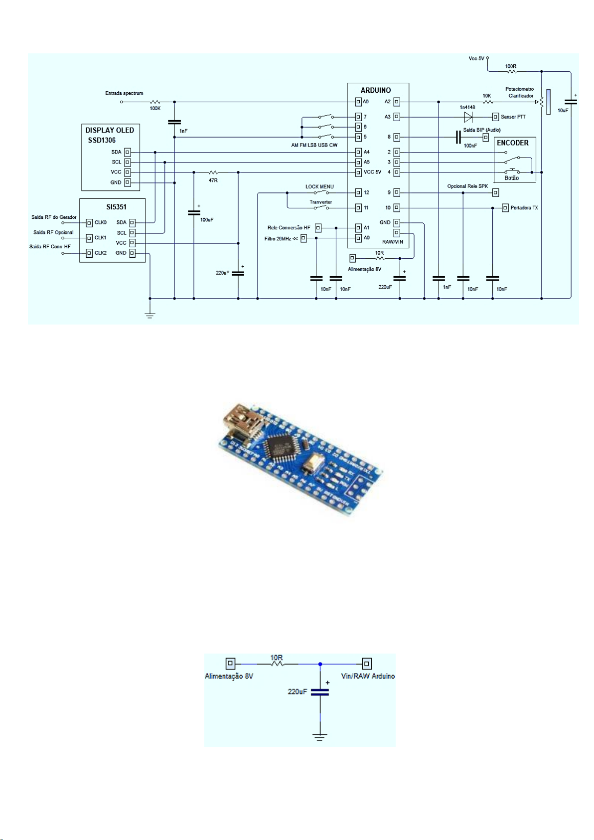
General circuit diagram
Arduino module power
The Arduino module already has a 5V voltage regulator, but because the Arduino is a very low consumption circuit, the
regulator used is for low current, to avoid damage, try to use voltage around 8V. It is interesting to use a 10R resistor and
a capacitor from 220uF to 1000uF at the power input, this works as an RC filter, blocking noises that can return and be
amplified by the radio's audio amplifier circuit. At the same time, this RC circuit acts as a current limiter that helps to
protect the Arduino module in the event of a short circuit in the 5V line. The VCC pin and 5V pin on the Arduino, is already
a voltage-stabilized output, however the current is very low, but it is more than enough to power the SI5351 display and
module.
11
Page 12
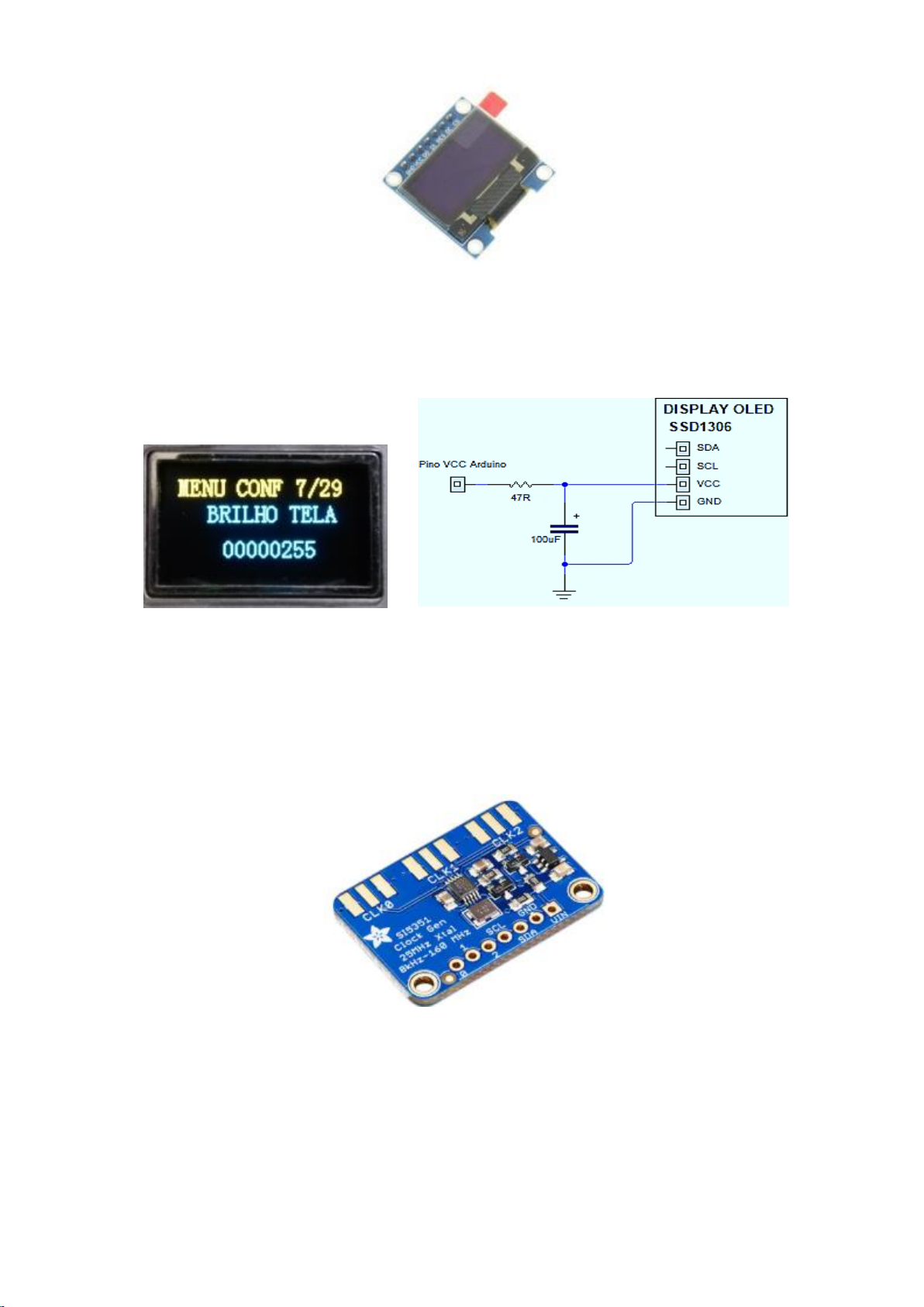
Power for SSD1306 Display
To use the display in circuits as a radio transceiver, it is necessary that the power be through an RC filter, because this
display has OLED technology that maintains the multiplexing of the LEDs that will form the pixels of the screen and this
multiplexing returns to the radio circuit, being amplified by the audio amplifier circuit, resulting in a characteristic noise to
a vibration of a loop relay.
The DDS WLG 6.22 system has a display brightness adjustment, this adjustment can be defined in item 7 of the settings
menu. The SDA terminal of the display is connected to pin A4 of the Arduino and the SCL terminal of the display is
connected to pin A5 of the Arduino.
Feeding and alignment of SI5351 module
The SI5351 module does not require a specific filter at the power input, as it has a 3.3V regulator of great quality and very
low noise, it is also not necessary to use a converter for the logic voltage level, as it already has 2 mosfets performing this
5V conversion to 3.3V.
The SI5351 SDA terminal is connected to the Arduino pin A4 and the SI5351 SCL terminal is connected to the Arduino pin
A5.
12
Page 13
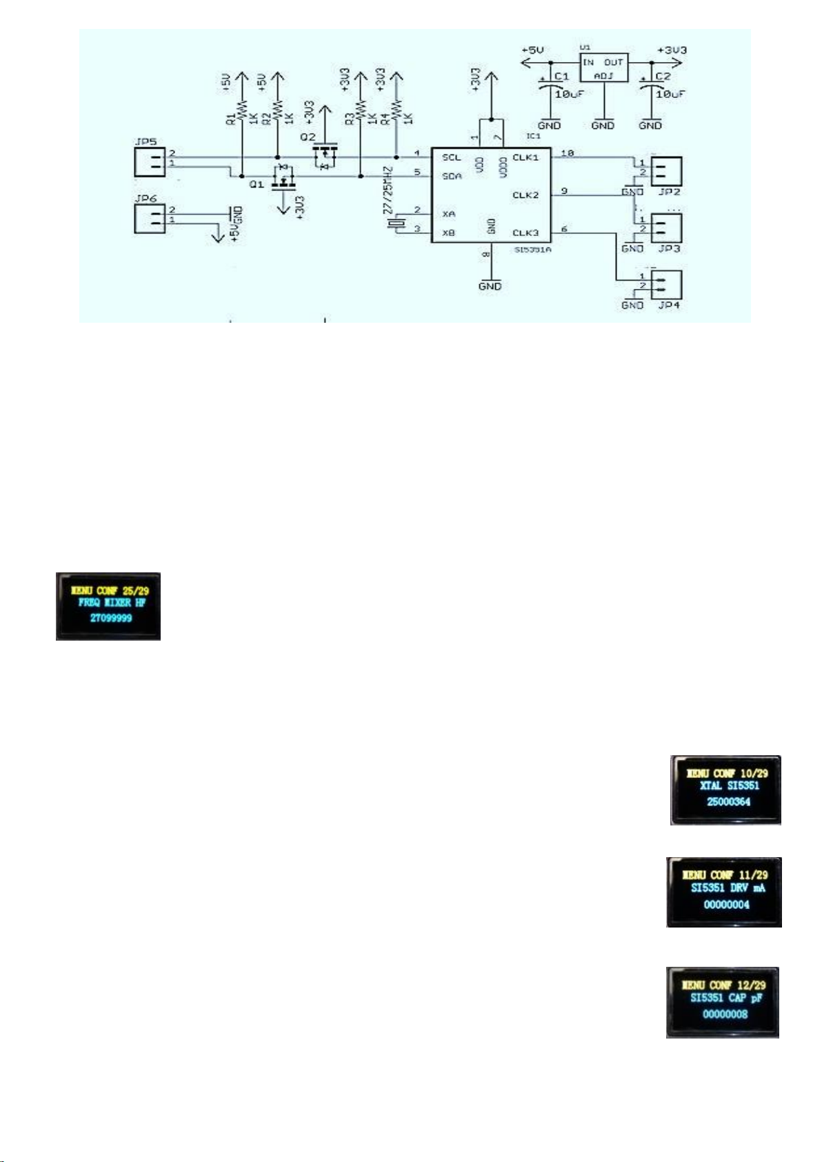
The SI5351 module has 3 frequency independent outputs, in the DDS WLG system we will use the CLK0 output as the
main RF generator replacing the original VCO system and forming the digital VFO system.
We have the output CLK1 that can be ignored or if you need an extra generator, you can define a fixed frequency in the
output CLK1, which can be defined in item 13 of the service menu. This frequency can be any frequency between 400KHz
up to 99MHz.
At the CLK2 output, the system generates a summation frequency for the HF “receiving” card mixer. The formula is very
simple, so that you understand the operation perfectly, the calculation is as follows:
Suppose you will hear the frequency of 7,153MHz, CLK2 will generate 19,847MHz (CLK2 = 27MHz - 7,153)
The 27MHz is a fixed frequency that you must define in item 25 of the settings menu.
This frequency is necessary to leave your radio on a fixed PX Channel, so, every conversion will be delivered on that
frequency. In case of spurious conversion, the clarifying potentiometer will act directly at this fixed frequency.
The settings menu has 4 items that will act directly on the SI5351 module. The items 10, 11, 12 and 13.
At tem 10 you must inform and adjust the frequency of the reference crystal used in the SI5351
module, the most common is 25MHz. This frequency must be defined in Hz and requires alignment.
In item 11 you must inform the current of the drive present in the SI5351 you intend to use, this
adjustment can be made when aligning the coil L19 and L20 in the case of a 148 GTL. Values are 4,
6 or 8mA.
At item 12 determines the 2 capacitors for the reference crystal, these capacitors are internal to
the SI5351 and can be set between 4, 6, 8, 10pF. In case of 25MHz reference crystal, leave the
value at 8pF. This adjustment is not critical, but if you change the capacitance value, a new
alignment in item 10 will be necessary.
13
Page 14
At item 13 is only an option to generate at the CLK1 output of the SI5351, any frequency that can
start at 400KHz up to 99MHz. I like to generate 20MHz to align the reference crystal in 10 item. If
you are not going to use the CLK1 output, it is important that you never leave values defined in
item 13, as this causes unnecessary noise.
How do I align the SI5351 module?
You will need a reliable frequency meter that has at least 8 digits.
Connect the frequency meter to the CLK1 output of SI5351, enter the system settings menu DDS WLG 6.22, go to item 13
and set a frequency between 10MHz (10 000 000) to 30MHz (30 000 000) observe the reading on your frequency meter,
go to item 12 and set the crystal to 8pF (depending on the value of the crystal used in SI5351), if the frequency read on
the frequency meter is different from the value defined in item 13, go to item 10 and adjust the final squares and keep
watching the value being displayed on your frequency meter, when that value is exactly like the value defined in item 13,
go back to item 13 and change the frequency value and observe the reading on the frequency meter, confirming that the
alignment is correct, put a zero at the frequency of item 13 and it’s done.
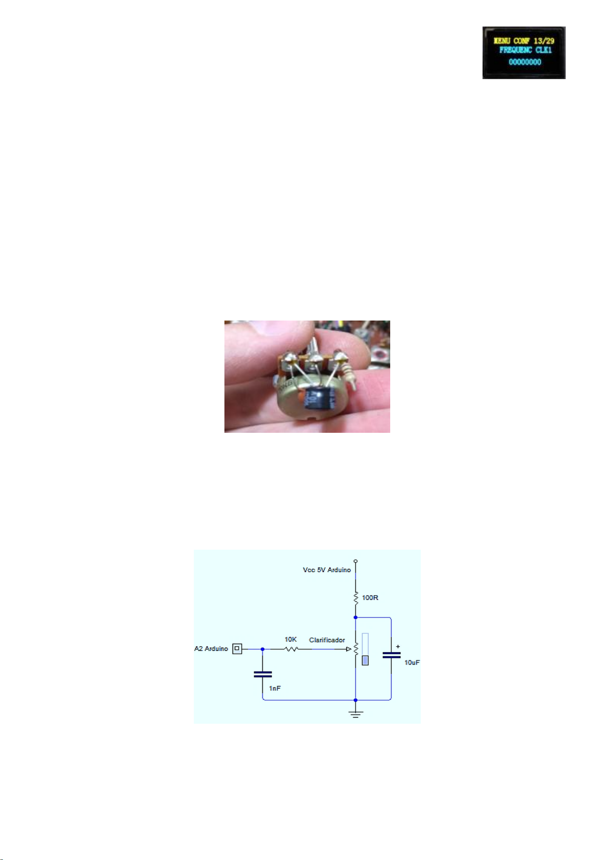
Clarifying potentiometer (VOICE LOCK)
It is suggested to use a filter for the clarifying potentiometer, which in addition to stabilizing the voltage and avoiding
unwanted jumps in the “frequency meter” in channel mode, protects the potentiometer in case of accidentally grounding
the central pin. It is not recommended to use pots with values below 5K, but above 5K you can use any value up to about
470K. The potentiometer must receive 5V voltage at the side terminals and the adjustable voltage at the central terminal
will be used to determine which tuning step has been deviated by adding or subtracting the value in the “frequency
meter” in channel mode.The central terminal of the potentiometer is connected to pin A2 of the Arduino.
In DDS WLG systems (any version) the clarifying potentiometer has two functions, the first function is the most common
and is for the use of tuning in channel mode, which can vary up to 10KHz upwards or 10KHz downwards, depending on
how it was defined the Hz value in item 24 of the settings menu.
14
Page 15
The second use for the clarifying potentiometer is for the RADIO RECEPTOR mode which when performing a frequency
mix, converting the entire input to the fixed frequency that was defined in item 25 of the settings menu, so that mix may
contain spurious and these spurious can deflected with the clarifying potentiometer that will act directly on the fixed
frequency of item 25 of the settings menu.
Filtering the output pins of the Arduino module.
It is also important to use a capacitor from 10nF to 100nF in all 4 Arduino output pins, as these pins will be delivered to
the base of a bipolar transistor and these transistors can amplify noise generated by the set of modules that complete the
DDS circuit.
A1 will be delivered to the base of a transistor to switch the switching relay of the RX HF board
D10 it will switch the carrier (TX) on the radio, through a transistor too.
A0 it is an option to activate filters on top of some coils, making a larger bandwidth.
D9 can be used as an option for cutting the speaker in TX mode through a relay.
It was suggested by some people to use a 1nF capacitor on the SCL pin to the GND of the display, but I was very insecure
with the use of this capacitor with such a high value on the I2C protocol clock. (If you using, test values less than 1nF. Try
something like 100pF, however, this filter is no longer needed in version 6.22, as it was proposed to eliminate the noise
caused by i2c communication, and in version 6.22, this communication is not more constant, because we don’t have a
display update at a fixed frequency, we have the display update and also the SI5351 constantly only in the spectrum scan,
but the frequency will be running, so it makes no sense to filter out noise where there will only be noise.)
Encoders
Installing and configuring the encoder.
The encoder is similar to 3 buttons (including, in the DDS WLG system you can use 3 buttons, instead of the encoder), the
encoder is installed by connecting the CLK terminals on the D2 pin Arduino, DT on the D3 pin Arduino and SW on the D4
pin of the Arduino, if you do not want to use power on the encoder, remove the pullup resistors present on the encoder
15
Page 16
board, as the DDS system already has these internal resistors, but if you are using the encoder with a plate and resistors,
it will be necessary to supply 5V on the + terminal of the encoder plate.
The CLK terminal is connected to the Arduino pin D2, the DT terminal is connected to the Arduino pin D3, the SW terminal
is connected to the Arduino pin D4.
The DDS WLG system is designed to work with 2 different encoder models, which can be selected
in item 28 of the settings menu. The most common is type 4, which will be noticed in the system.
If you use a model different from the model selected in item 28, it will be observed when you
rotate the encoder once and it takes 2 steps, or it may happen that you rotate twice to occur just
1 step; if this is happening, enter item 28 and change from type 4 to type 2 or each other.
Another thing that can happen is that the direction is reversed.
To invert the direction of direction, enter item 29 and adjust by selecting the value 0 or 1.
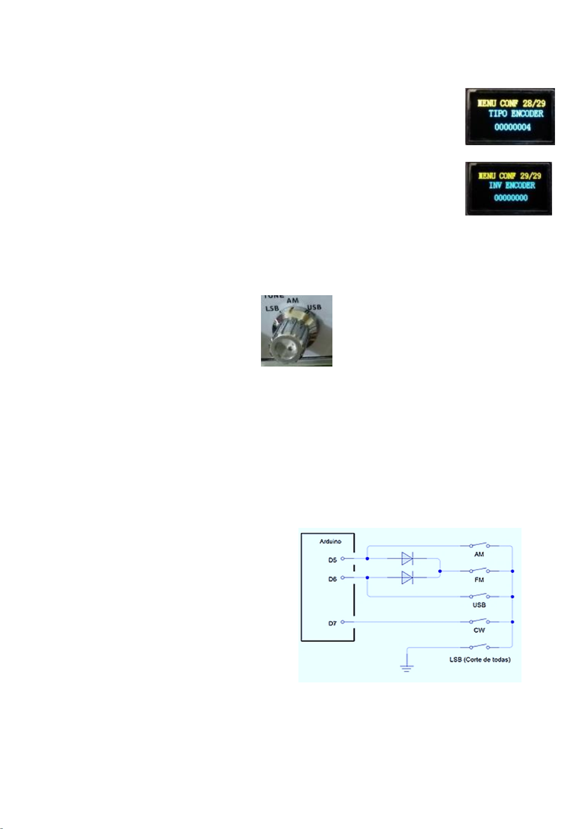
Modulation mode switch (known on the PX as a bandwidth switch)
The DDS WLG system always provides a way to adapt to different radio models, for this the system checks the position of
the key of the modulation mode of your equipment, this verification is done through a low logical level, that is, taking the
corresponding Arduino’s pins to the ground. For the arduino to identify this difference, it is necessary that the pin has a
voltage of 5V present. We call this a pullup which is a resistor usually 10K connecting the Arduino pin up to 5V, so that the
arduino recognizes this change in logic level from 5V to 0V, you should just ground the pin that already has this pullup
resistor internally.
The system was designed to read a combination for up to 5 modulation modes, which are AM, FM, CW, USB, LSB
To identify these positions, the system will use Arduino pins D5, D6, D7.
See a table for the combinations:
D5 in GND ....................................... AM mode
D6 in GND ....................................... USB mode
D5 and D6 GND ................................ FM mode
D7 in GND ....................................... CW mode
No pins in GND ................................ LSB mode
Depending on the radio model, it will be necessary to perform a universal voltage switch. This switching requires 2 bipolar
NPN transistors. This in case of being installed in radios that have only AM, USB, LSB. In the diagram of the universal
voltage switching, you will easily identify what I am explaining, as the necessary thing is to ground the corresponding pins
on the Arduino, so the use of the transistor is exactly to make this ground through the collector that will be connected
directly to the corresponding pin of the Arduino, the emitter plays directly to the ground and the base receives the
voltage from the radio circuit that made the switching of the modulation mode selected by the switch.
16
Page 17
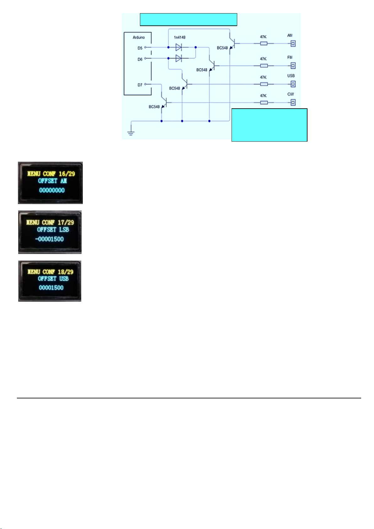
Universal voltage switching
that way, you can use the
voltage points of the mode
switch, the LSB mode will be
in the absence of all
In the settings menu, these pins act on items 16, 17, 18.
The item 16 will measure a deviation that can add or subtract the value entered in the item
(OFFSET AM).
The item 17 will measure a deviation that can add or subtract the value entered in the item
(OFFSET LSB).
The item 18 will measure a deviation that can add or subtract the value entered in the item (USB
OFFSET).
_______________________________________________________________________________________________
FM and CW offsets are not present in the menu, as in PX radios, these modulation modes use the AM offset.
These adjustments are made in Hz and do not replace the radio main Carrier, here only a calibration should be done for a
higher frequency accuracy.
The offset patterns are:
1.5KHz for Cobra models and 2.5KHz for Voyager models.
PTT sensor
This time the DDS WLG system has a beep and for the beep to work, it is necessary to read the PTT key, as this way the
system knows when it is being transmitted and waits as long as necessary before emitting the beep.
The installation of the key is very simple, however, you will have to be pay attention and careful in this installation, as it is
one of the most risky, have the risk of burning the Arduino module. For that not to happen we will use a 1n4148 diode
between the A3 pin’s Arduino and the point on the radio connector where it is grounded when we press the PTT button.
17
Page 18
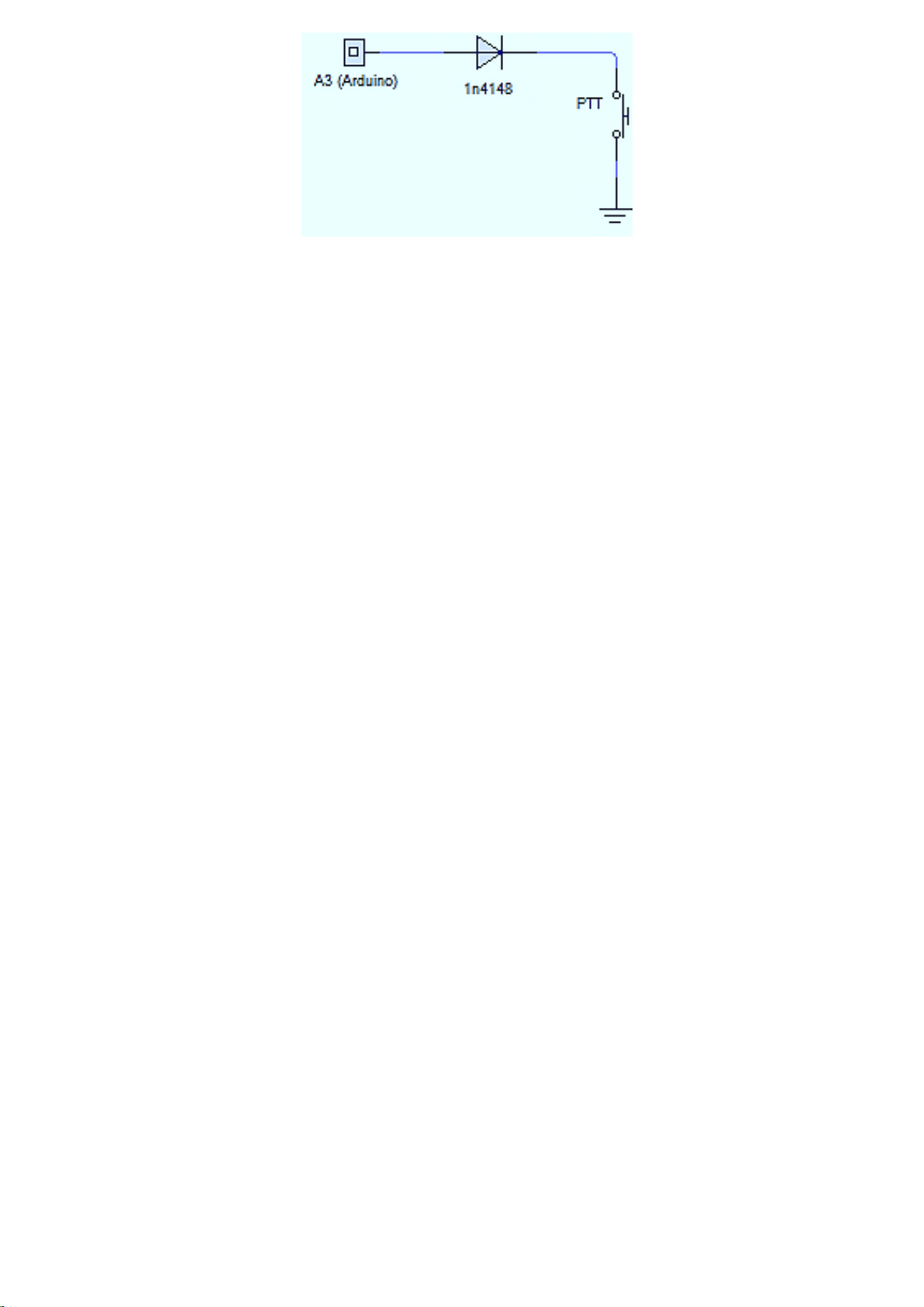
The reason for this diode is in case the installation of this pin is done at a point where the PTT switch will be grounding a
voltage of 8V, so this 8V cannot be delivered to pin A3 of the Arduino, because the maximum voltage limit on the pin of
the Arduino is 5V. Technically it works like this: A3 pin needs a constant voltage of 5V to inform the system that the radio
is not transmitting, this voltage is the Pullup that should use a resistor generally 10K between VCC 5V and the
corresponding pin on Arduino, on case here, pin A3. To inform the system that the radio is transmitting, pin A3 must be
grounded, reducing the voltage from 5V to less than 2V, so the system will understand that the radio is transmitting. By
connecting the anode to a general purpose diode and grounding the cathode, pin A3 will have a reduction of 5V to
approximately 700mV which is well below 2V and thus the system will understand it as a low logical level. So the diode is
only protecting the Arduino in case of a voltage return above 5V on A3 pin, but if you removed the PTT switch from the
radio circuit that makes the TX and you are sure that there is no voltage returning, no it is necessary to use the diode.
Cutting Loudspeaker and Arming Carrier through the DDS system (BEEP Circuit)
As the new DDS system monitors the use of PTT, the system now controls the right moment to arm a carrier on your radio
through the Arduino D10 pin. This pin remains at 0V until the PTT is pressed, but as soon as the PTT sensor detects that it
hears the PTT button being pressed, the system checks the interval value in item 3 of the settings menu and makes a time
correction between D9 pin and D10 pin. The D9 pin of the Arduino is an option to correct an initial noise that can occur in
the speaker, when you press the PTT, because if the system turns off the speaker and arm carrier in the same interval, the
radio circuit will allow to generate a brief popping sound on the speaker, so that this doesn’t happen, the system will first
switch off the relay via D9 pin.
The proposed circuit using a specific Arduino pin for the loudspeaker cutout relay and a specific pin for arm carrier, must
be made using a general purpose NPN bipolar transistor and a 12V relay that has a normally closed contact for the
loudspeaker cut and 10K resistor between D9 pin and base of the transistor, to eliminate noise, use a 100nF capacitor
between base and ground. To arm carrier use a general purpose bipolar NPN transistor and 10K resistor between pin D10
and base of the transistor, to eliminate noise, use 100nF capacitor between base and ground.
18
Page 19
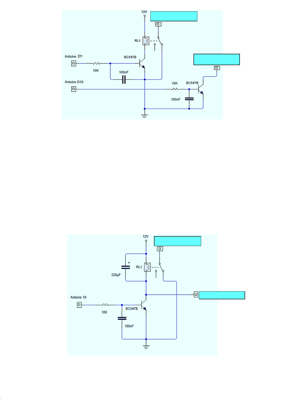
the SPK (green) wire
The Carrier Terminal
the SPK (green) wire
On the radio, it will be necessary to remove a wire from terminal 3 of the PTT connector, in the case of the 148 GTL radio,
this is the green wire that cuts the speaker through the PTT switch. Removing this wire, this same wire will be connected
to the SPK (green) wire terminal of the beep circuit. The Carrier Terminal of the beep circuit will be connected to the wire
that was removed from terminal 5 of the PTT connector. (You removed a wire from terminal 5 to connect a PTT sensor
diode, it is exactly this wire that has 8V, in this case, as you removed this wire from terminal 5, it is not necessary to use
the diode, but I recommend using it like this).
But there is a more common form used in almost all beep circuits which is using only one Arduino pin to arm carrier and
arm relay that cuts speaker at the same time. But it does not correct the initial noise, it only corrects the final noise. In
this circuit the relay activates the carrier and cuts the speaker at the same time, and depending on the radio, it will be
possible to hear a brief noise similar to a burst in the speaker, as soon as the PTT is pressed, but when releasing the PTT,
the carrier cuts shortly before the relay resets the speaker. This time correction is done through the 220µF capacitor, this
capacitor must be adjusted depending on the impedance of the relay used.
19
Page 20
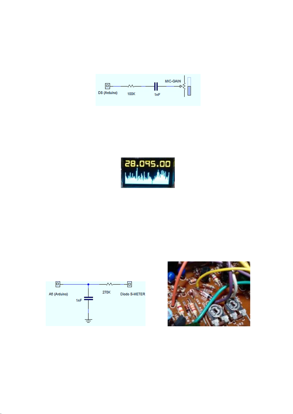
Audio output for BEEP
With the new feature in the system that allows you to place polyphonic BEEPs on your radio without the need for an
external beep plate, the system makes use of the Arduino D8 pin to generate the beep sounds. There are several ways to
match this audio output to your radio, the most common of which is to input audio into the MIC-GAIN pot next to the
microphone. What is necessary is that you use a resistor of about 100K and a capacitor of a maximum of 100nF. On 148
GTL radio models, you can simply use a 100K resistor followed by a 1nF capacitor and connect directly to the central
terminal of the MIC-GAIN potentiometer.
But this match will depend on how it will look on your radio, because in some cases, it may be that someone has made
changes to the original audio circuit of the radio and this match is not good, so adjust the capacitor for a better result.
Installing the spectrum sensor and auto-scan
The new DDS 6.27 system has a spectrum scanning function that can be used as a tool for perfect radio alignment. This
spectrum allows to scan the entire frequency limit that was defined in items 19 and 20 of the service menu, and can be
used in the RADIO RECEPTOR mode by sweeping the entire limit defined in items 26 and 27 of the service menu. The use
is very simple and for you have more details on how to use, see the page about the system's operating modes.
The maximum voltage for the spectrum scanning sensor is 1.1V. I will detail here the installation on a Cobra 148 GTL
radio, but it can be done on any other radio model, as we’ll use the reference of the radio's S-Meter.
The most indicated point in the 148 GTL is at the anode of the D71 diode which is delivering the signal to the S-METER
adjustment trimpots. Use a 270K resistor between the diode anode and the Arduino pin A6, also use a 1nF capacitor
between the Arduino pin A6 and GND. (Higher values for the 1nF capacitor can be tested. This capacitor will act by
filtering the spectrum graph on the screen).
20
Page 21
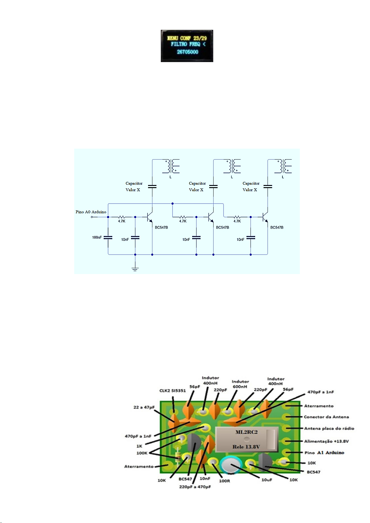
Using item 23 of the settings menu (Filter for negative channels).
This is an additional feature that requires a lot of technique and patience too, as it is basically a realignment of coils for
use with negative channels. This feature will always be activating the Arduino A0 pin at 5V output, when the frequency
value in the DDS system is in VFO mode or Channel mode is below the value of item 23 of the settings menu. The
technician will be able to use capacitors on the corresponding coils and these capacitors will be switched through an NPN
BC547 transistor.
In summary, the Arduino A0 pin will have a 5V output whenever the system frequency is below the filter frequency in
item 23.
The diagram only shows how this switching can be done. In this example, only 3 coils are being used.
About converting to RADIO RECEPTOR mode
The RADIO RECEPTOR or HF Receiver mode is an option in the DDS system that allows you to hear frequencies below the
11 m range of the PX. In this mode, the system will perform a frequency calculation, generating at the CLK2 output of the
SI5351 a frequency equivalent to the frequency of 25 item of the settings menu less the frequency being displayed in the
VFO of the RECEIVER RADIO mode. To make use of the RECEIVER RADIO function, it’ll be necessary to use a MIXER plate
that can be easily made using general purpose components.
List of required components:
2 - BC547 Bipolar NPN Transistors
1 - Relay model ML2RC2 (12V)
2 - 100K resistors
3 - 10K resistors
1 - 1K resistor
1 - 100R resistor
1 - 10nF ceramic capacitor
3 - 470pF ceramic capacitors
2 - 220pF ceramic capacitors
2 - 56pF ceramic capacitors
1 - 22pF ceramic capacitor
21
Page 22
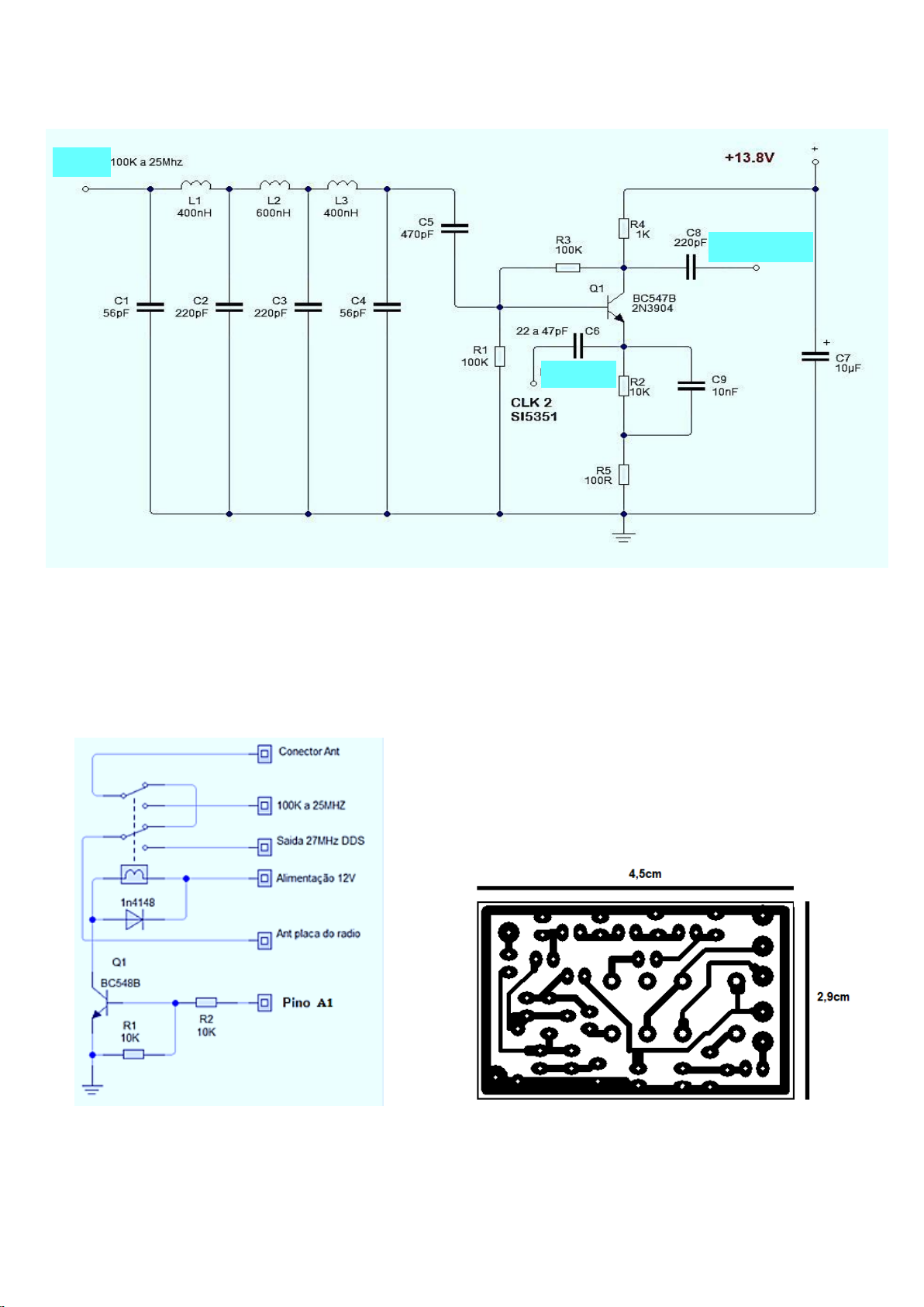
1 - 22pF ceramic capacitor
Input
Input DDS
Output 27Mhz
2 - 400nH Inductors (Can be made by wrapping 16 turns of 32 Awg wire over 1M resistor)
1 - 600nH Inductor (Can be made by winding 22 turns of 32 Awg wire over 1M resistor)
The transistor used was a BC547, because it is easy to be found, but for a better result you can check possible substitutes
indicated for RF, also try placing a FET, for example, a 2n7000.
The PCB board is also very simple to make.
This mixer card, will provide a great reception between 500KHz to 14MHz, you can try to go up to 21MHz, but above
14MHz the reception will drop a lot, because the filter starts to cut. The conversion has no selective filter, requiring a
specific antenna for the band you want to receive. To use the conversion card, enter the user menu using option 2 of the
22
Page 23
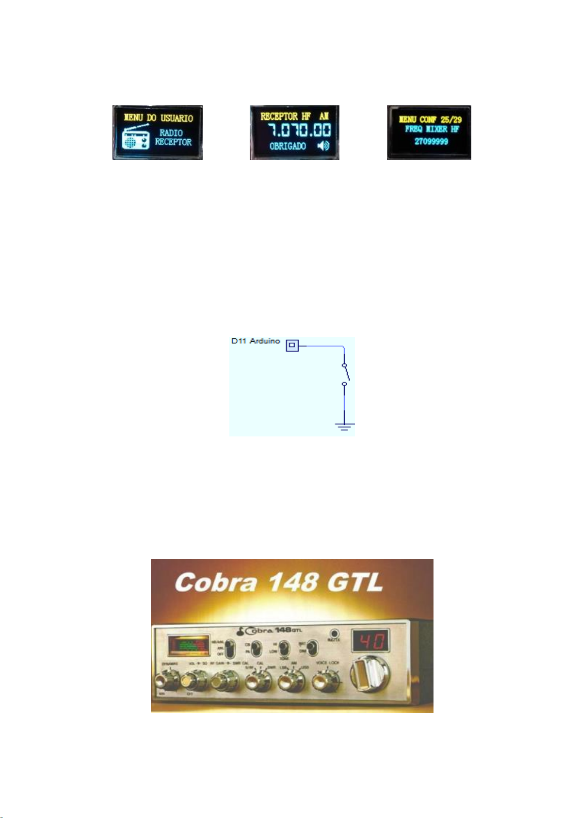
encoder switch button, select the RECEIVER RADIO icon and use any of the 3 button options to access this mode. Note:
for better reception, adjust item 25 of the settings menu by placing the radio on a fixed frequency in the 11M band.
Choose a frequency that isn’t exactly a Channel and preferably where you don’t usually have many rounds and if you
happen to hear beats, the potentiometer starts to act in the RECEIVER RADIO mode making a frequency deviation in the
conversion.
Using the Transverter function
This function will only display the correct frequency in case of using an external transverter. Here the user can adjust item
9 of the settings menu to add or subtract a value in the VFO frequency display. For example, if you place the radio in a
conventional 40M transverter, generally the conversion frequency will be removing 20MHz to deliver to the PX, so if the
radio is on channel 30 (27,305.00) and is using a 40M transverter, it will receiving, actually, (7.305.00) but without using
the correction function in the DDS system, it will be displayed 27.305.00. Passing the key to the transverter mode, which
is grounding the D11 pin of the Arduino, the system makes a calculation by adding or subtracting the value in item 9 of
the settings menu, as it will probably be in -20000000 in item 9, the system will make 27.305.000 - 20000000 = 7.
Installing DDS on a Cobra 148 GTL radio
This part of the manual is entirely focused on installing the DDS KIT on a Cobra 148 GTL transceiver, but as you have
already noticed, the DDS WLG 6.27 system is quite versatile and can adapt to any other radio model, including the old HF
transceivers .
23
Page 24
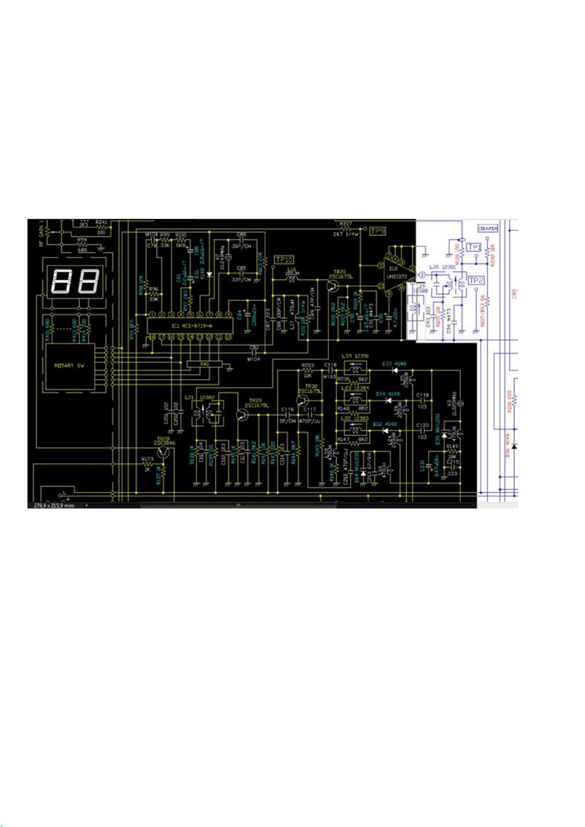
NOTE: Reading only this part of the manual, you will not understand how to install BEEP, Spectrum, PTT and other
items. Do not skip steps. Read the entire manual from the beginning.
Preparing the radio for DDS installation
First step is to remove the original VCO system. (But don't do it yet, read and understand, as you can also maintain and
use the UHIC070 module)
To give you an idea, see in this diagram what can be eliminated in a Cobra 148 GTL radio. (Any dark part can be eliminated
without a problem).
On the board you will get an even better idea. (Do not remove L19).
24
Page 25
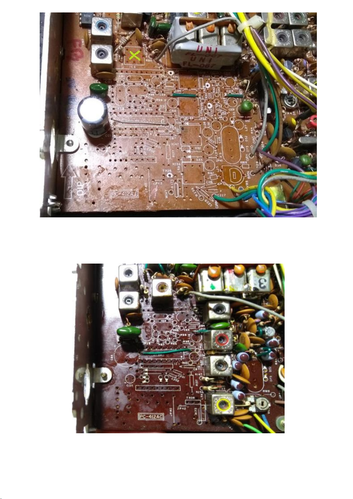
With the exception of the L19 coil which will now be used in this new installation.
The following photo shows what we are actually going to remove to effect the DDS modification. Note: the C84 capacitor
was removed just to facilitate the assembly, but after adding the SI5351 module, put the 1000µF C84 capacitor again.
After removing these components, you will need:
1 - Transistor 2SC1675 (You can use what was removed)
1 - Resistor 100R (Has one near the TR29, can be removed and used)
25
Page 26
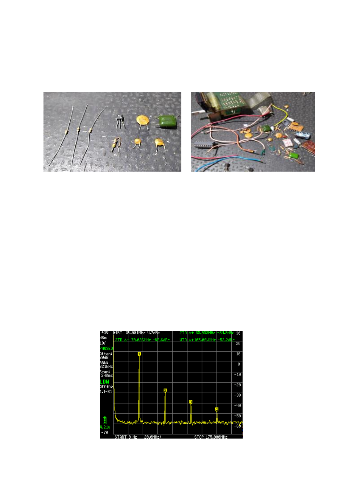
1 - Resistor 470R (You can use two 1K in parallel if not found)
1 - Resistor 1K (You can use what was removed)
1 - 4K7 resistor (You can use two of 2K2 or one of 2K2 and the other of 2k7 in series if not found)
1 - Capacitor 18pF (You can use what was removed)
1 - Capacitor 47pF (You can use what was removed)
1 - 10nF Capacitor (You can use what was removed)
1 - 100nF Capacitor (You can use what was removed)
Separate parts. Parts was removed.
Only the 470R and 4K7 resistors you will not find in the middle of those that were removed, but you can use 2 to form the
value of 1 as suggested in the material list.
With this separate material, you will analyze the diagram of the buffer and on the radio plate, using the positions of the
removed components, you will assemble the new buffer, repositioning the components in the material list.
(This requires technique).
Buffer for the main output of the DDS system.
Originally, your radio uses the VCO UHIC070 module, which was designed for a 40-channel radio, using a spectrum
analyzer at the point TP1 of the L20 coil, the fundamental amplitude of this signal is on average 4.7dBm with the second
harmonic around -34.9dBm below the fundamental. Of course, the ideal is to maintain these standards, but generally, the
enthusiast would like to have as many channels as possible, and this will not be possible if he wants to keep the original
standards.
If you go out of this standard and increase this amplitude, you will have a better performance in the additional
channels, however, you will also have a noisier reception and, in the end, this was not beneficial, because the
rest of the radio was not designed to accompany these channels additional, but there is a technique that can be
26
Page 27
done and will allow to have a better performance in the additional channels, which is using pin A0 and item 23
of the service menu. (I won't go into detail, because if you've read the manual so far, you already know about
it.)
In summary: After a modification by DDS, the whole system was limited to generating a frequency respecting
the standards of the offsets and the final product will be at point TP1 of the L20 coil in case the radio is a Cobra
148 GTL.
Installing th main buffer.
At this stage of the installation, you probably already understood how the Arduino module should be powered, how to
turn on the display, how to turn on the SI5351, how to turn on and filter the clarifying potentiometer (VOICE LOCK) and
also have already learned about the switch modulation mode. If you have not read and do not know the reason for these
steps, I suggest you start first by reading this manual.
A little about the old buffer.
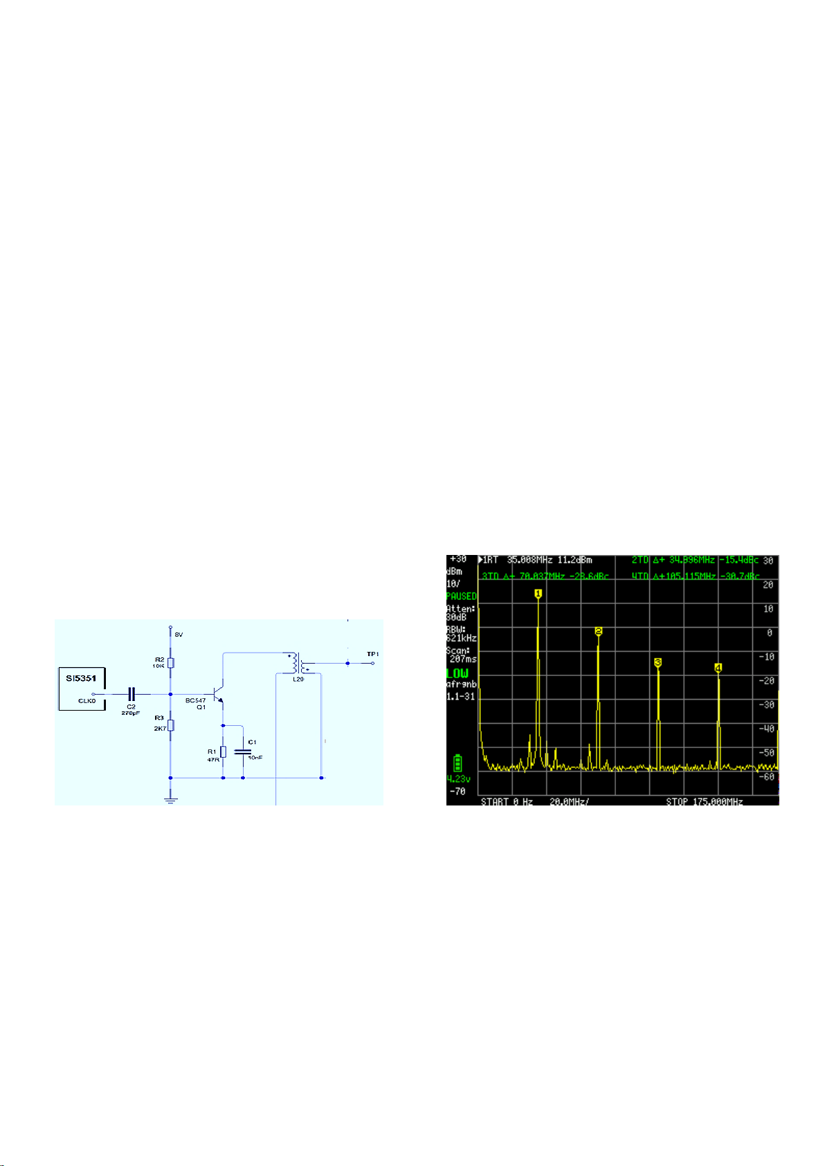
In my first modification on the 148 GTL, doing tests and practicing my hobby as an amateur radio, following the diagram I
saw that the main point where the DDS should work would be on the L20 coil, because the VCO + PLL and Cristal X3 set of
11.325MHz, worked together and they were delivered to the L20 coil that had fixed frequencies on its output depending
on the selected channel and had a 1.5KHz deviation above the AM or below the AM, depending on the position of the
USB mode switch, LSB, so the main point was the L20 coil. After writing down some reference frequencies for some
channels, I removed the whole set of analog circuit VCO + PLL and oscillator 11.325 and went to work on the L20, with
lack of knowledge and desire to do something simple, I made a buffer using a BC547 transistor on L20 coil and the result
was perfect modulation and reception, so I kept my first buffer that ruled out using the L19 coil.
As can be seen in the spectrum above, the fundamental amplitude is higher than the original level, and this will provide
you with a better performance in the additional channels, but the reception becomes noisier.
Today I no longer recommend this old buffer, although it works very well and allows a very wide band of channels on the
radio, it is not a recommended circuit, it amplifies many spurious. We are using the SI5351 module as the main RF
generator that works with digital output forming a square wave, although the L20 coil filters this wave, transforming it
into a sine wave, the buffer is not well calculated to maintain a standard amplitude at the output TP1 and for this we have
a very large bandwidth, being able to define up to 1000 channels in a radio, but as the radio was designed for 40
channels, this is an illusion, because we do not have filters being switched to allow so many channels, however, this is not
a lie in the system, in fact you can define 1000 channels using this buffer, so much so that I did a test with the friend and I
modulated in the side band from 21MHz to 29.5MHz, only that it was only in one direction, I just did this transmission,
but if I had to receive it, I would never be able to, because as explained, the radio was not designed for this bandwidth. In
27
Page 28
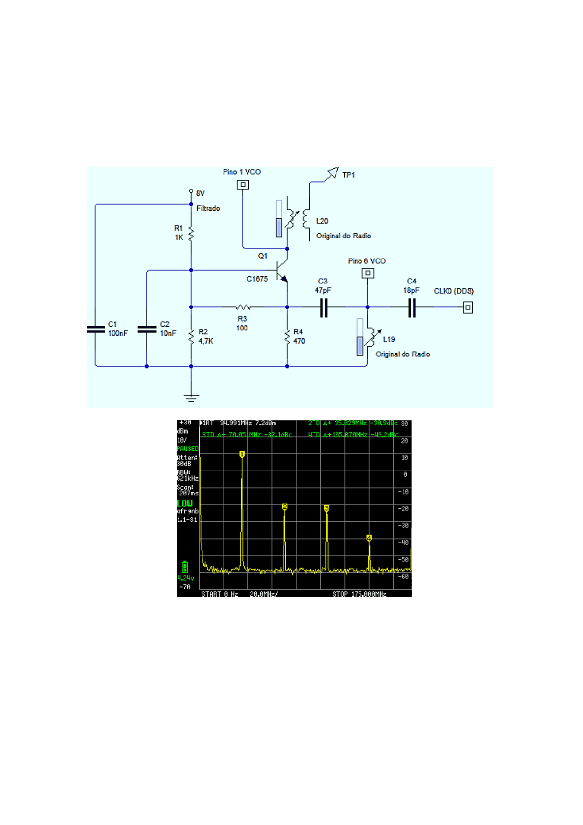
summary, the old buffer was updated to maintain an amplitude equivalent to the original system and now the L19 coil is
being used, which will narrow the band, allowing a maximum of 40 negative channels and 120 positive channels, but with
the guarantee of maintaining the quality of the analog VCO + PLL system.
New buffer.
The new buffer can be made using components that will be unusable on the radio itself, because after modification by
DDS on your Radio Cobra 148 GTL, an original part of the radio will be inoperable.
The new buffer allows for more bandwidth, and will keep reception quiet.
You can assemble by positioning the components in the vacant position after removing the unnecessary components.
28
Page 29
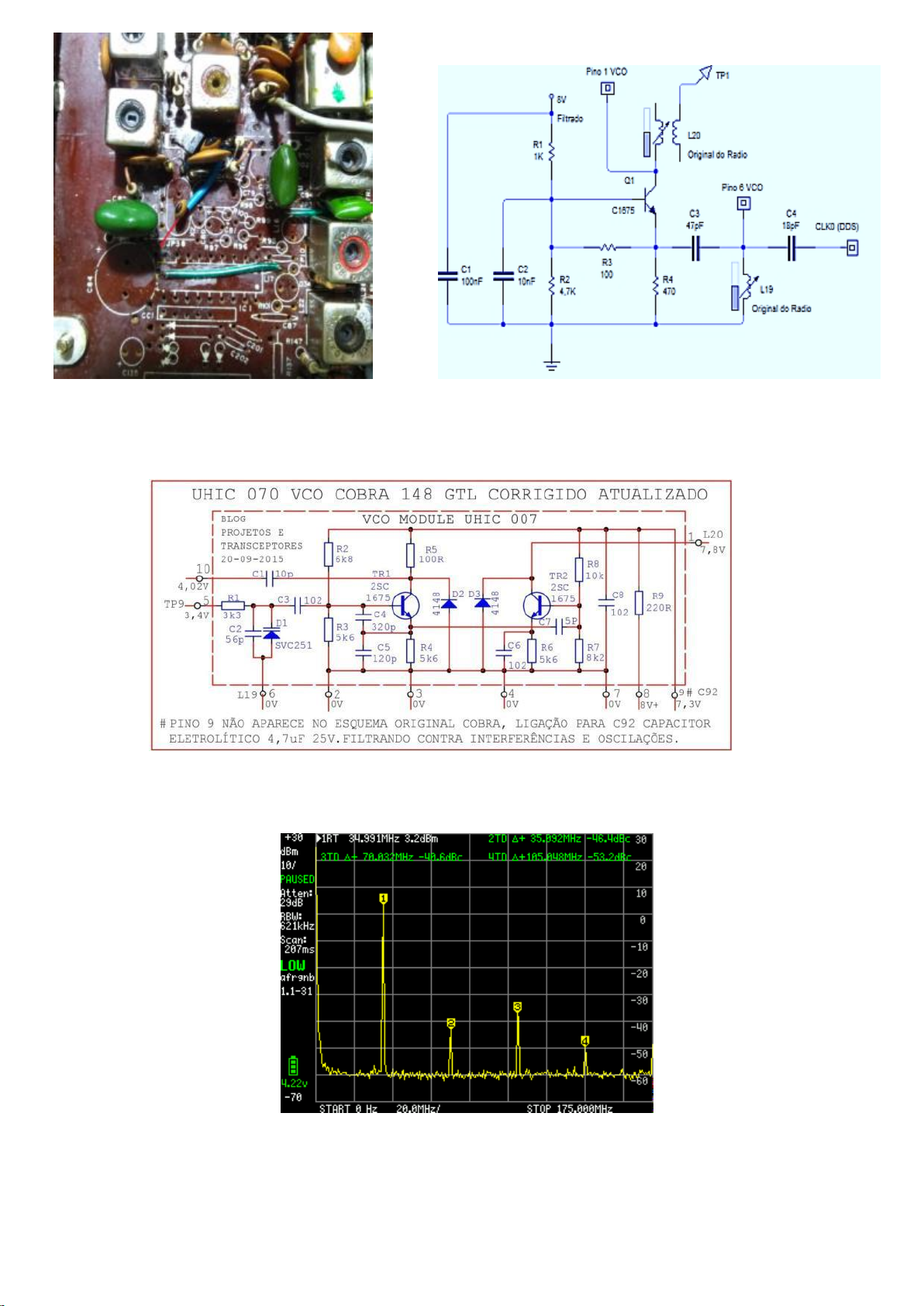
Keeping the original 148GTL UCO VHIC070
Installation can also be carried out, maintaining the original VCO, the performance in the additional channels will be
lower, but the standard will be slightly lower than the original and the result will be a much quieter reception.
29
Page 30
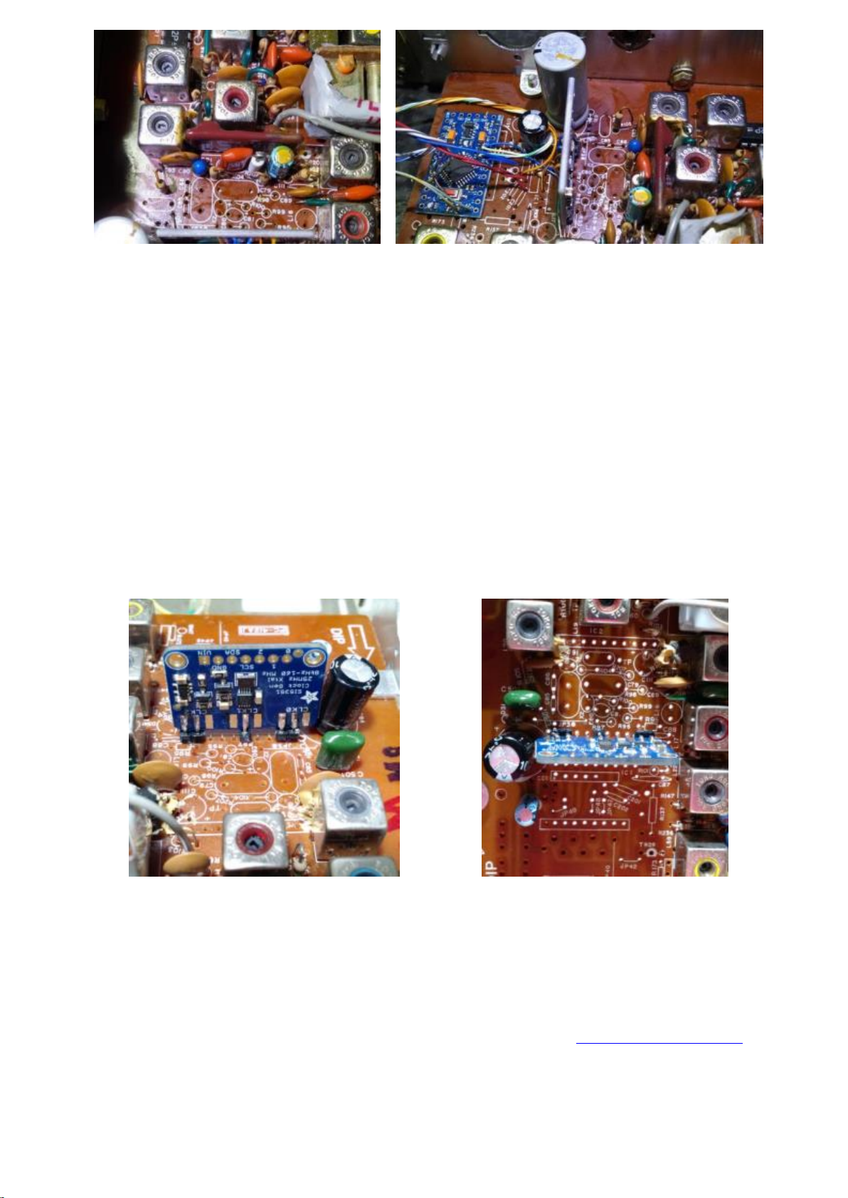
The CLK0 output of the SI5351 module will be delivered to pin 6 of the VCO, along with L19 coil. (It is not necessary to use
a capacitor, but if you are going to use it, use a 100pF capacitor between CLK0 and pin 6.) To keep the VCO module in
place, it will be necessary to keep the following components.
IC2 - UHIC070 C93 - 10nF R102 - 2K2
L19 - 12380 C92 - 4,7µF R103 - 2k2
C91 - 47µF R104 - 1K
C90 - 0.47µF R105 - 100R
Installing the SI5351 module
Now that you have the buffer made in place, you can install the SI5351 module. The most indicated place on the radio
plate is exactly where the PLL was. Good grounding on the SI5351 module is important.
Up to this point in the installation, your radio is already prepared to receive the Arduino module.
Installing the Arduino module.
For information on how to write the firmware on the Arduino module, visit the blog www.kitdds.blogspot.com
This is without a doubt the most complex and tiring step of the modification. You will position the Arduino in place, easier
for you to connect the wires, here there is no rule to be followed, just connect everything correctly. A detail of the entire
pinout is on page 4 of this manual.
30
Page 31
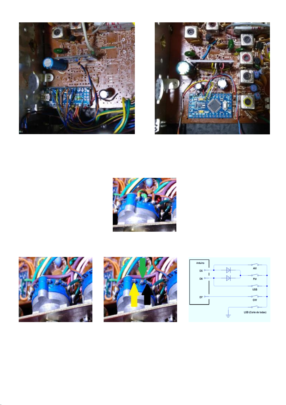
The following images are just a suggestion of how and where you can place your Arduino.
Installing and configuring the modulation mode switch.
Using DDS on a Cobra 148 GTL radio, we already have terminals left on the modulation switch, which can be perfectly
used to inform the Arduino, where the switch is located.
Note that there are 3 free terminals, depending on the radio version, the switch may be placed in another direction and
the free terminals are on the other side of the radio chassis. At the point indicated with yellow arrow, you will connect to
the D5 terminal of the Arduino, making the identification of the AM position, the point indicated with the green arrow,
you will connect to the D6 terminal of the Arduino, making the identification of the USB position and the indicated
terminal with black arrow, you will connect to the circuit ground. The LSB position will be identified by the system, when
there is no grounding at pin D5 and D6. In short: D5 left terminal (AM), D6 middle terminal (USB) and fully right terminal,
GND. This way the key will be requesting AM mode and USB mode, LSB mode is in the absence of these two requests.
31
Page 32
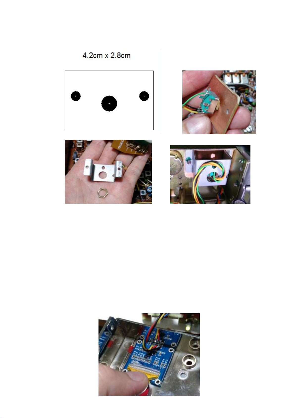
Install the encoder switch now
As support for the encoder, it will be necessary to cut a 4.2cm x 2.8cm plate. (1,66in x 1,10in)
With a screw with nut to secure the 4.2cm x 2.8cm (1,66in x 1,10in) plate, the original selector switch holder can be used.
The encoder can be installed with the original plate on the models for Arduino, or without this plate as shown in these
photos above, however, if the encoder is used with the plate, note that it has 2 or 3 pullup resistors. These resistors must
be removed if the encoder is not supplied with 5V on the + VCC pin. If you don't want to power, just remove the resistors,
as the DDS system already uses Arduino's internal pullup.
Installing Display
Here at this stage of the installation, you have to be very careful, as the display is very fragile and any error, however
small, it will damage the display.
32
Page 33
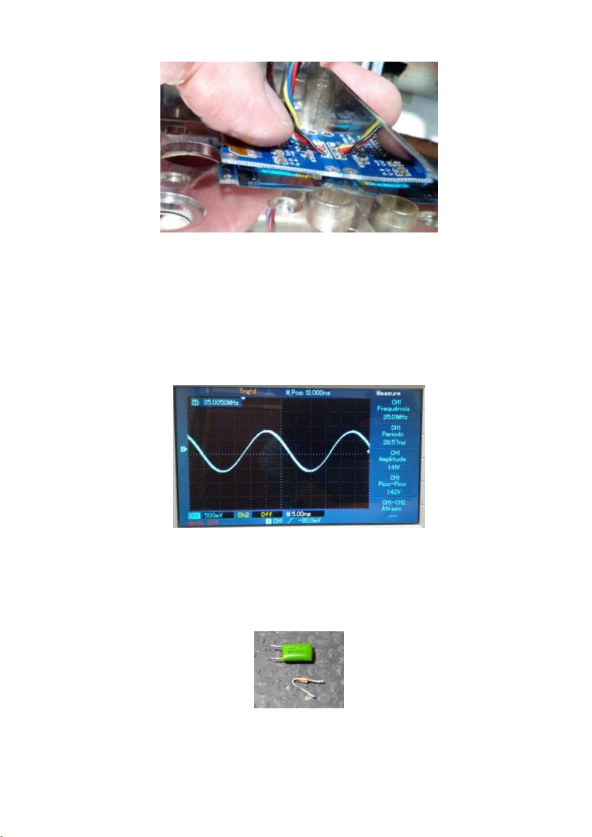
When accommodating the display, observe if it was not touching any corner of the display in any relief of the panel, if this
occurs, surely your display will be broken as soon as you fix the panel screws.
In some cases, it will be necessary to use a mini grinder to make the display fit correctly, if you are not achieving a visual
alignment of the display, use a thermal blower (hair dryer will do) and blow the display plate well, release the glass and
position a little higher or lower, aligning perfectly. The best way to fix the display is to use hot glue.
Aligning L19 coil and L20 coil
After everything assembled and working. The time has come to leave everything well adjusted.
It will not be necessary to use an oscilloscope, what should be done is just use a 1n4148 diode and a 47nF capacitor
connecting to point TP1 (L20 output) a multimeter.
This diode plus the capacitor were removed from the radio itself.
33
Page 34
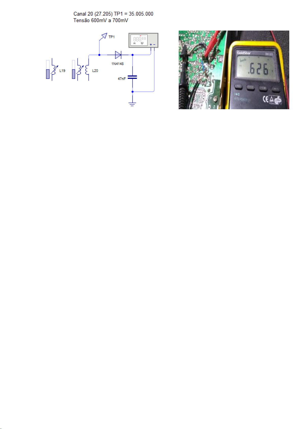
Solder the diode anode at point TP1 of the L20 coil and at the diode cathode weld a 47nF capacitor to the ground.
Between cathode and ground, connect a multimeter in continuous voltage reading, put the radio in bandwidth mode at
the frequency of 27.205.00 enter the settings menu and go to item 11, lower the drive to 2mA and observe the voltage
reading on the multimeter. Adjust L20 to the maximum voltage point, after L20 is at the peak voltage, adjust L19 until the
maximum voltage peak is obtained. If the reading is within 600mV to 700mV everything is fine, but if the voltage is too
low, you can go up the driver in item 11 from 2mA to 4, 6, 8 and redo the alignment on L20 and L19.
After all, leave the settings menu, go back to the running band mode, remove the external radio antenna, leave the RF
GAIN in maximum and check how the alignment was using the spectrum scanning function of the DDS system itself 6.27
giving too much spurious, adjust the coil L19 or L20, as it may have been a little out.
Problems and solutions
No information is appearing on the display
The DDS WLG 6.27 system has an operating priority which is to initialize the display (the system needs the display to
proceed with initialization), if the display is not showing any information, check whether the LED on pin D13 is on or
flashing. If it is blinking, the problem is a defective display, but if the LED on pin D13 is direct access, the problem could be
a display defect or simply a short on the line of the i2c A4 pin and A5 pin of the Arduino.
Solution: Remove the SI5351 and check if the display will work; if it doesn't work, replace the display.
System constantly locking
This can also be a problem related to the display or simply some noise on the i2c line. Check that the display does not
have any of its terminals touching the radio chassis, any noise caused on the i2c line, can lock the system. If using
capacitors between Clock (SCL) or DATA (DAS) to GND, lower the value of this capacitor, as this capacitor helps to clear
noise on the i2c line, but if the capacitance value is too high, data loss will occur in the line i2c and the system will lock up.
Solution: Check the Arduino i2c line, pin A4 and A5.
Encoder does not work
You are probably using the encoder with a plate, in which case it is necessary to remove the pullup resistors or simply
supply the encoder with 5V on the (+ terminal). Do not have one, do a pullup for pin D2 with a resistor value below 10K
between VDC 5V and another pullup for pin D3.
Solution: Pullup on pins D2 and D3 of the Arduino, or replacement of the encoder.
Encoder skipping 2 in 2 values or having to turn twice to a single value
Solution: Change the value of item 28 of the settings menu.
34
Page 35

Inverted encoder
Solution: invert pins D2 and D3 of the arduino or invert encoder in item 28 of the settings menu.
Clarifying potentiometer is not acting
Solution: Check if it has value in item 24 of the settings menu. Check if there is voltage variation on pin A2 as you move
the potentiometer to the right or left.
Not broadcasting
Solution: Check if it has value in item 8 of the settings menu. Check if the PTT makes voltage below 2V on pin A3. Check
that when pressing PTT, there is 5V on pins D9 and D10 of the Arduino.
Loud humming speaker with closed volume
Solution: Make RC filter with 47R resistor and 100µF capacitor to supply the display. Use separate voltage regulator for
the Arduino module.
Speaker giving pop sound when pressing or releasing PTT
Solution: Check the value in item 3 of the settings menu. Make BEEP circuit using D9 and D10 pin from Arduino.
Settings menu is not appearing in the user menu
Solution: Remove ground from D12 pin on the Arduino.
It's generating a lot of spurious
Solution: Reset the value of item 13 in the settings menu. Decrease driver value in item 11 of the settings menu. Align L19
and L20.
____________________________________________________________________
35
 Loading...