

DDM Brands ANDY AC4E, ANDY AC4EW User Manual
DDM Brands LLC
3G MOBILE PHONE
Main Model: AC4E
Serial Model: ANDY AC4E, AC4EW
December 06, 2013
Report No.: 13070549-FCC-R3
(This report supersedes none)
Modifications made to the product : None
This Test Report is Issued Under the Authority of:
Back Huang
Compliance Engineer
Alex Liu
Technical Manager
This test report may be reproduced in full only.
Test result presented in this test report is applicable to the representative sample only.
Title: RF Test Report for 3G MOBILE PHONE
Main Model: AC4E
Serial Model: ANDY AC4E, AC4EW
To: FCC Part 15.247: 2013, ANSI C63.4: 2009
Report No.: 13070549-FCC-R3
Issue Date: December 06, 2013
Page: 2 of 74
www.siemic.com.cn
Laboratory Introduction
SIEMIC, headquartered in the heart of Silicon Valley, with superior facilities in US and Asia, is one of the
leading independent testing and certification facilities providing customers with one-stop shop services for
Compliance Testing and Global Certifications.
In addition to testing
and certification, SIEMIC provides initial design reviews and compliance
management through out a project. Our extensive experience with China, Asia Pacific, North America,
European, and international compliance requirements, assures the fastest, most cost effective way to attain
regulatory compliance for the global markets
.
SIEMIC (Shenzhen-China) Laboratories Accreditations for Conformity Assessment
Country/Region Scope
USA EMC , RF/Wireless , Telecom
Canada EMC, RF/Wireless , Telecom
Taiwan EMC, RF, Telecom , Safety
Hong Kong RF/Wireless ,Telecom
Australia EMC, RF, Telecom , Safety
Korea EMI, EMS, RF , Telecom, Safety
Japan EMI, RF/Wireless, Telecom
Singapore EMC , RF , Telecom
Europe EMC, RF, Telecom , Safety

Title: RF Test Report for 3G MOBILE PHONE
Main Model: AC4E
Serial Model: ANDY AC4E, AC4EW
To: FCC Part 15.247: 2013, ANSI C63.4: 2009
Report No.: 13070549-FCC-R3
Issue Date: December 06, 2013
Page: 3 of 74
www.siemic.com.cn
This page has been left blank intentionally.

Title: RF Test Report for 3G MOBILE PHONE
Main Model: AC4E
Serial Model: ANDY AC4E, AC4EW
To: FCC Part 15.247: 2013, ANSI C63.4: 2009
Report No.: 13070549-FCC-R3
Issue Date: December 06, 2013
Page: 4 of 74
www.siemic.com.cn
CONTENTS
1 EXECUTIVE SUMMARY & EUT INFORMATION .......................................................................................... 5
2 TECHNICAL DETAILS ......................................................................................................................................... 6
3 MODIFICATION ..................................................................................................................................................... 7
4 TEST SUMMARY .................................................................................................................................................... 8
5 MEASUREMENTS, EXAMINATION AND DERIVED RESULTS .................................................................. 9
ANNEX A. TEST INSTRUMENT & METHOD ........................................................................................................ 52
ANNEX B. EUT AND TEST SETUP PHOTOGRAPHS ........................................................................................... 57
ANNEX C. TEST SETUP AND SUPPORTING EQUIPMENT ................................................................................ 69
ANNEX D. USER MANUAL / BLOCK DIAGRAM / SCHEMATICS / PART LIST ............................................. 73
ANNEX E. DECLARATION OF SIMILARITY ........................................................................................................ 74

Title: RF Test Report for 3G MOBILE PHONE
Main Model: AC4E
Serial Model: ANDY AC4E, AC4EW
To: FCC Part 15.247: 2013, ANSI C63.4: 2009
Report No.: 13070549-FCC-R3
Issue Date: December 06, 2013
Page: 5 of 74
www.siemic.com.cn
1 EXECUTIVE SUMMARY & EUT INFORMATION
The purpose of this test programme was to demonstrate compliance of the DDM Brands LLC,
3G MOBILE PHONE and model: AC4E against the current Stipulated Standards. The 3G
MOBILE PHONE has demonstrated compliance with the FCC Part 15.247: 2013, ANSI C63.4:
2009.
EUT Information
EUT
Description
: 3G MOBILE PHONE
Main Model
:
AC4E
Serial Model
:
ANDY AC4E, AC4EW (the Difference Between Main Model and Serial
Model is Only Colour of the Appearance)
Antenna Gain
:
UMTS-FDD Band V/GSM850: -3 dBi
UMTS-FDD Band II/PCS1900: 0 dBi
Bluetooth/ WIFI: 0 dBi
GPS: -1 dBi
Input Power
:
Battery:
Model: YB117
Capacity: 1550 mAh 5.74 wh
Nominal Voltage: 3.7 V
Charging Voltage Limit: 4.2 V
Adapter:
Model: YW12
Input: AC 100-240V 50/60Hz 150 mA
Output: DC 5.0 V 550 mA
Classification
Per Stipulated
Test Standard
: FCC Part 15.247: 2013, ANSI C63.4: 2009

Title: RF Test Report for 3G MOBILE PHONE
Main Model: AC4E
Serial Model: ANDY AC4E, AC4EW
To: FCC Part 15.247: 2013, ANSI C63.4: 2009
Report No.: 13070549-FCC-R3
Issue Date: December 06, 2013
Page: 6 of 74
www.siemic.com.cn
2 TECHNICAL DETAILS
Purpose Compliance testing of 3G MOBILE PHONE with stipulated standard
Applicant / Client
DDM Brands LLC
1616 NW, 84TH Ave. Miami, Florida, U.S.A 33126
Manufacturer
DDM Brands LLC
A-401, HengYu Center, NanShan, ShenZhen, China518054
Laboratory performing
the tests
SIEMIC (Shenzhen-China) Laboratories
Zone A, Floor 1, Building 2, Wan Ye Long Technology Park, South Side of
Zhoushi Road, Bao'an District, Shenzhen, Guangdong, China
Tel: +86-0755-2601 4629 / 2601 4953
Fax: +86-0755-2601 4953-810
Email: China@siemic.com.cn
Test report reference
number
13070549-FCC-R3
Date EUT received November 14, 2013
Standard applied FCC Part 15.247: 2013, ANSI C63.4: 2009
Dates of test November 26, 2013 to November 29, 2013
No of Units : #1
Equipment Category : Spread Spectrum System/Device
Trade Name : YEZZ
RF Operating Frequency
(ies)
GSM850 TX : 824.2 ~ 848.8 MHz; RX : 869.2 ~ 893.8 MHz
PCS1900 TX : 1850.2 ~ 1909.8 MHz; RX : 1930.2 ~ 1989.8 MHz
UMTS-FDD BandⅤTX : 826.4 ~ 846.6 MHz; RX : 871.4 ~ 891.6 MHz
UMTS-FDD BandⅡTX :1852.4 ~ 1907.6 MHz; RX : 1932.4 ~ 1987.6 MHz
802.11b/g/n(20): 2412-2462 MHz
Bluetooth: 2402-2480 MHz
Number of Channels
299CH (PCS1900) and 124CH (GSM850)
UMTS-FDD BandⅤ: 102CH
UMTS-FDD BandⅡ: 277CH
Bluetooth: 79CH
802.11b/g/n(20): 11CH
Modulation
GSM / GPRS: GMSK
UMTS-FDD: QPSK
802.11b/g/n(20): DSSS/OFDM
Bluetooth: GFSK&π/4DQPSK&8DPSK
GPRS Multi-slot class 8/10/12
FCC ID A4JANDYA4E

Title: RF Test Report for 3G MOBILE PHONE
Main Model: AC4E
Serial Model: ANDY AC4E, AC4EW
To: FCC Part 15.247: 2013, ANSI C63.4: 2009
Report No.: 13070549-FCC-R3
Issue Date: December 06, 2013
Page: 7 of 74
www.siemic.com.cn
3 MODIFICATION
NONE
Title: RF Test Report for 3G MOBILE PHONE
Main Model: AC4E
Serial Model: ANDY AC4E, AC4EW
To: FCC Part 15.247: 2013, ANSI C63.4: 2009
Report No.: 13070549-FCC-R3
Issue Date: December 06, 2013
Page: 8 of 74
www.siemic.com.cn
4 TEST SUMMARY
The product was tested in accordance with the following specifications.
All testing has been performed according to below product classification:
Test Results Summary
FCC Rules Description of Test Result
§15.247 (i), §2.1093 RF Exposure Compliance
§15.203 Antenna Requirement Compliance
§15.247 (a)(2)
DTS (6 dB&26 dB) CHANNEL BANDWIDTH Compliance
§15.247(b)(3)
Conducted Maximum Output Power Compliance
§15.247(e)
Power Spectral Density Compliance
§15.247(d)
Band-Edge &
Unwanted Emissions into Non-Restricted
Frequency Bands
Compliance
§15.207 (a), AC Power Line Conducted Emissions Compliance
§15.205, §15.209,
§15.247(d)
Radiated Spurious Emissions &
Unwanted Emissions into Restricted Frequency
Bands
Compliance
Title: RF Test Report for 3G MOBILE PHONE
Main Model: AC4E
Serial Model: ANDY AC4E, AC4EW
To: FCC Part 15.247: 2013, ANSI C63.4: 2009
Report No.: 13070549-FCC-R3
Issue Date: December 06, 2013
Page: 9 of 74
www.siemic.com.cn
412.25/55.6
437.25/83.5
462.25/25.5
5 MEASUREMENTS, EXAMINATION AND DERIVED
RESULTS
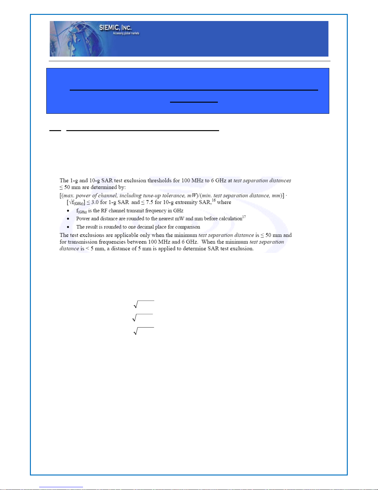
5.1 §15.247 (i) and §2.1093 – RF Exposure
Standard Requirement:
According to §15.247 (i) and §1.1307(b)(1), systems operating under the provisions of this section shall be operated in a
manner that ensures that the public is not exposed to radio frequency energy level in excess of the Commission’s
guidelines.
Routine SAR evaluation refers to that specifically required by § 2.1093, using measurements or computer simulation.
When routine SAR evaluation is not required, portable transmitters with output power greater than the applicable low
threshold require SAR evaluation to qualify for TCB approval.
Two antennas are available for the EUT (GSM/UMTS antenna and WIFI/Bluetooth/GPS antenna).
The maximum average output power(turn-up power) in low channel of WIFI is 8.16 dBm= 6.55 mW
The calculation results= = 2.03 < 3
The maximum average output power(turn-up power) in middle channel of WIFI is 7.66 dBm= 5.83 mW
The calculation results= = 1.82 < 3
The maximum average output power(turn-up power) in high channel of WIFI is 7.20 dBm= 5.25 mW
The calculation results= = 1.65 < 3
According to KDB 447498, no stand-alone required for WIFI antenna, and no simultaneous SAR measurement is
required .
Test Result: Pass
The SAR measurement is exempt.

Title: RF Test Report for 3G MOBILE PHONE
Main Model: AC4E
Serial Model: ANDY AC4E, AC4EW
To: FCC Part 15.247: 2013, ANSI C63.4: 2009
Report No.: 13070549-FCC-R3
Issue Date: December 06, 2013
Page: 10 of 74
www.siemic.com.cn
5.2 §15.203 - ANTENNA REQUIREMENT
Applicable Standard
According to § 15.203, an intentional radiator shall be designed to ensure that no antenna other than that furnished by
the responsible party shall be used with the device. The use of a permanently attached antenna or of an antenna that uses
a unique coupling to the intentional radiator shall be considered sufficient to comply with the provisions of this section.
The manufacturer may design the unit so that a broken antenna can be replaced by the user, but the user of a standard
antenna jack or electrical connector is prohibited. The structure and application of the EUT were analyzed to determine
compliance with section §15.203 of the rules. §15.203 state that the subject device must meet the following criteria:
a. Antenna must be permanently attached to the unit.
b. Antenna must use a unique type of connector to attach to the EUT.
Unit must be professionally installed, and installer shall be responsible for verifying that the correct antenna is
employed with the unit.
And according to FCC 47 CFR section 15.247 (b), if the transmitting antennas of directional gain greater than 6dBi are
used, the power shall be reduced by the amount in dB that the directional gain of the antenna exceeds 6 dBi.
Antenna Connector Construction
The EUT has 2 antennas: .a PIFA antenna for WIFI/Bluetooth/GPS, the gain is 0 dBi for WIFI/Bluetooth and -1 dBi
for GPS.
.a PIFA antenna for GSM and UMTS, the gain is -3 dBi for UMTS-FDD BandV/GSM850
and 0 dBi for UMTS-FDD Band II/PCS1900 .
which in accordance to section 15.203, please refer to the internal photos.
Result: Compliance.

Title: RF Test Report for 3G MOBILE PHONE
Main Model: AC4E
Serial Model: ANDY AC4E, AC4EW
To: FCC Part 15.247: 2013, ANSI C63.4: 2009
Report No.: 13070549-FCC-R3
Issue Date: December 06, 2013
Page: 11 of 74
www.siemic.com.cn
5.3 §15.247(a) (2) –DTS (6 dB&26 dB) CHANNEL BANDWIDTH
1. Conducted Measurement
EUT was set for low, mid, high channel with modulated mode and highest RF output power.
The spectrum analyzer was connected to the antenna terminal.
2. Environmental Conditions Temperature 24
o
C
Relative Humidity 45%
Atmospheric Pressure 1017mbar
3. Conducted Emissions Measurement Uncertainty
All test measurements carried out are traceable to national standards. The uncertainty of the measurement at
a confidence level of approximately 95% (in the case where distributions are normal), with a coverage factor
of 2, in the range 30MHz – 40GHz is ±1.5dB.
4. Test date : November 26, 2013
Tested By : Back Huang
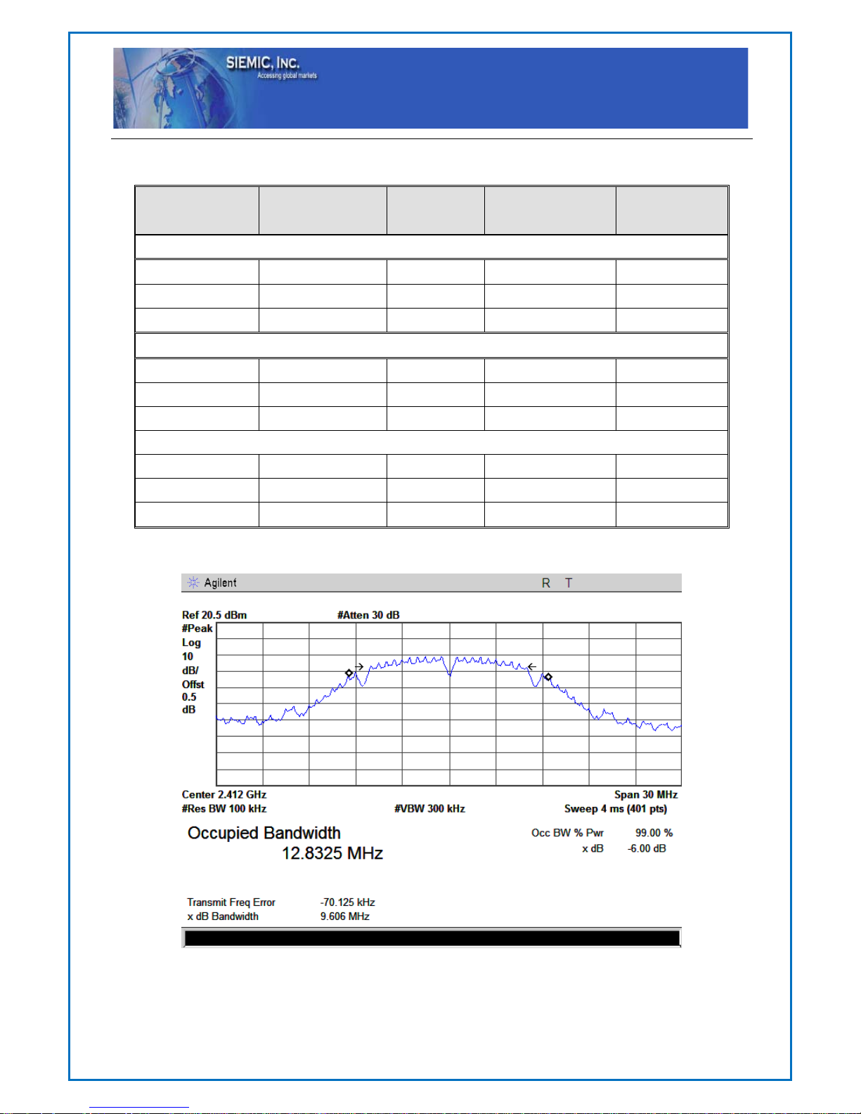
Requirement(s): The minimum 6 dB bandwidth of a DTS transmission shall be at least 500 kHz. Within this document,
this bandwidth is referred to as the DTS bandwidth. The procedures provided herein for measuring the maximum peak
conducted output power assume the use of the DTS bandwidth.
Procedures:
1. Set RBW = 100 kHz.
2. Set the video bandwidth (VBW) ≥ 3 x RBW.
3. Detector = Peak.
4. Trace mode = max hold.
5. Sweep = auto couple.
6. Allow the trace to stabilize.
7. Measure the maximum width of the emission that is constrained by the frequencies associated with the two outermost
amplitude points (upper and lower) that are attenuated by 6 dB relative to the maximum level measured in the
fundamental emission.
Test Result: Pass.
Please refer to the following tables and plots.
Title: RF Test Report for 3G MOBILE PHONE
Main Model: AC4E
Serial Model: ANDY AC4E, AC4EW
To: FCC Part 15.247: 2013, ANSI C63.4: 2009
Report No.: 13070549-FCC-R3
Issue Date: December 06, 2013
Page: 12 of 74
www.siemic.com.cn
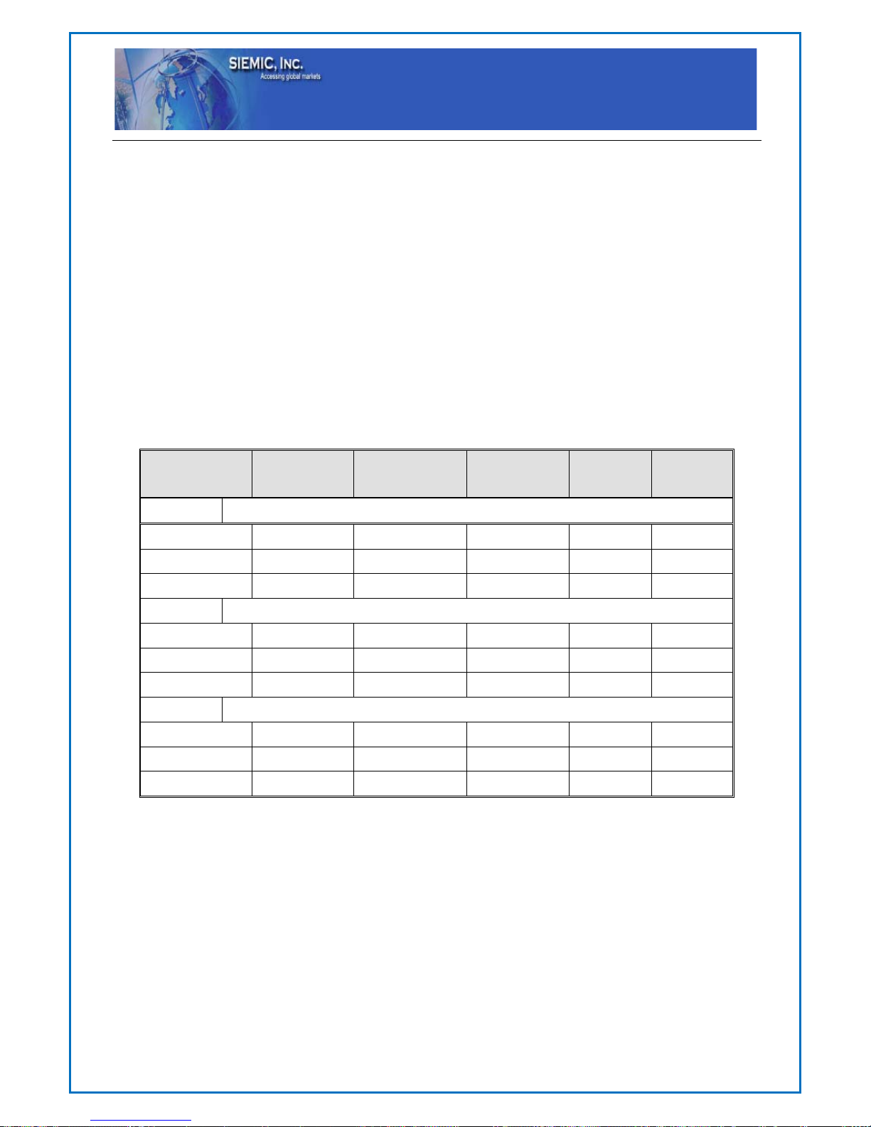
6dB bandwidth:
Channel
Channel
Frequency
(MHz)
Data Rate
(Mbps)
Measured
6dB Bandwidth
(MHz)
FCC Part 15.247
Limit
(kHz)
802.11b mode
Low 2412 1 9.606
>500
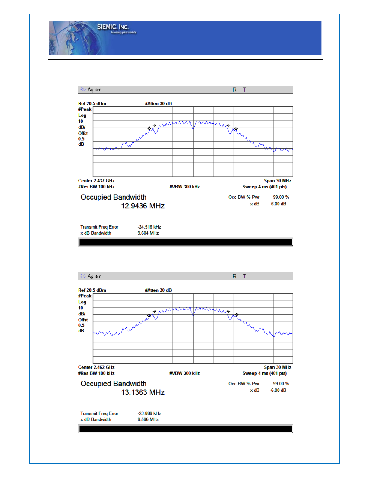
Middle 2437 1 9.604
>500
High 2462 1 9.596
>500
802.11g mode
Low 2412 6 16.440
>500
Middle 2437 6 16.438
>500
High 2462 6 16.416
>500
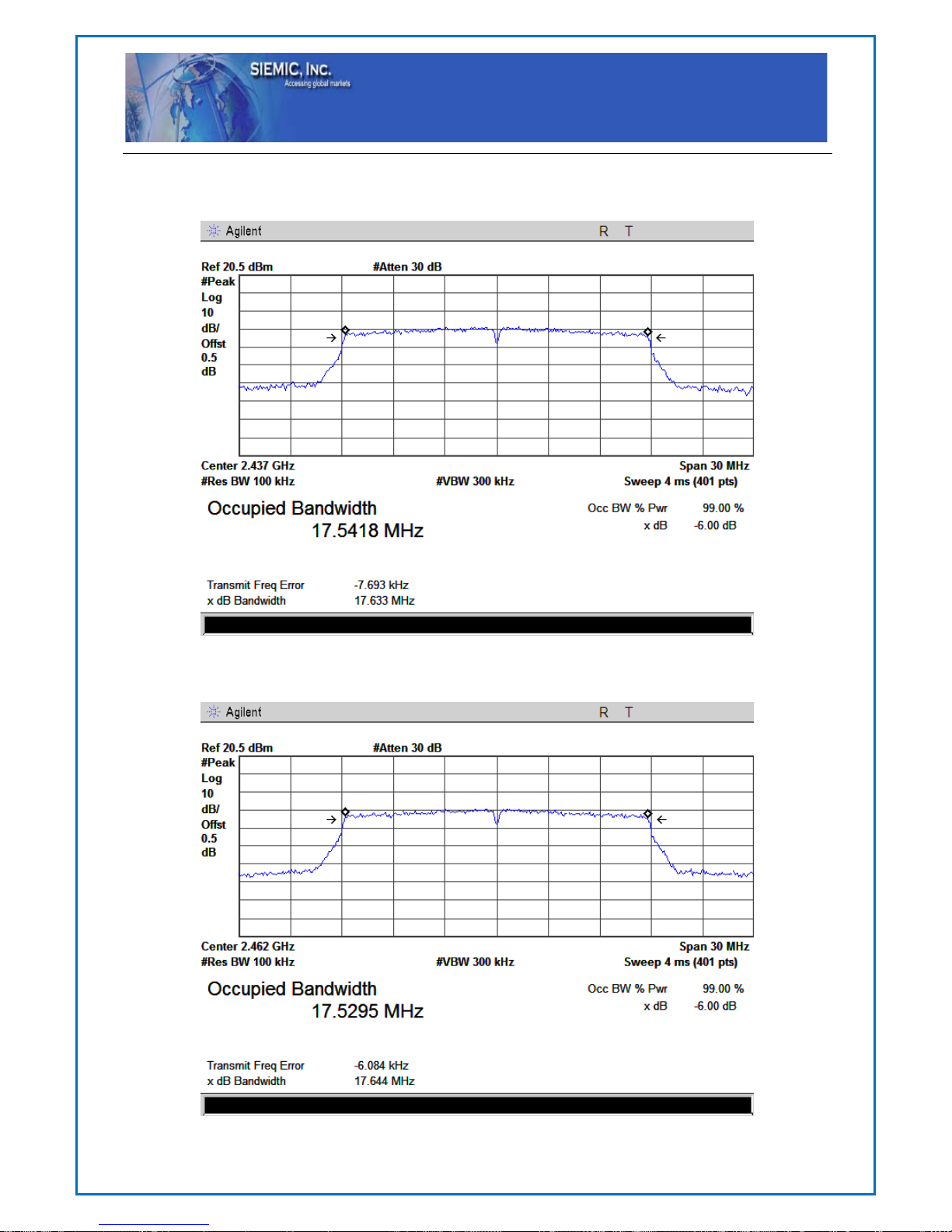
802.11n(20) mode
Low 2412 MCS0 17.637
>500
Middle 2437 MCS0 17.633
>500
High 2462 MCS0 17.644
>500
802.11b Low Channel
Title: RF Test Report for 3G MOBILE PHONE
Main Model: AC4E
Serial Model: ANDY AC4E, AC4EW
To: FCC Part 15.247: 2013, ANSI C63.4: 2009
Report No.: 13070549-FCC-R3
Issue Date: December 06, 2013
Page: 13 of 74
www.siemic.com.cn
802.11b Middle Channel
802.11b High Channel

Title: RF Test Report for 3G MOBILE PHONE
Main Model: AC4E
Serial Model: ANDY AC4E, AC4EW
To: FCC Part 15.247: 2013, ANSI C63.4: 2009
Report No.: 13070549-FCC-R3
Issue Date: December 06, 2013
Page: 14 of 74
www.siemic.com.cn
802.11g Low Channel
802.11g Middle Channel

Title: RF Test Report for 3G MOBILE PHONE
Main Model: AC4E
Serial Model: ANDY AC4E, AC4EW
To: FCC Part 15.247: 2013, ANSI C63.4: 2009
Report No.: 13070549-FCC-R3
Issue Date: December 06, 2013
Page: 15 of 74
www.siemic.com.cn
802.11g High Channel
802.11n Low Channel
Title: RF Test Report for 3G MOBILE PHONE
Main Model: AC4E
Serial Model: ANDY AC4E, AC4EW
To: FCC Part 15.247: 2013, ANSI C63.4: 2009
Report No.: 13070549-FCC-R3
Issue Date: December 06, 2013
Page: 16 of 74
www.siemic.com.cn
802.11n Middle Channel
802.11n High Channel
Title: RF Test Report for 3G MOBILE PHONE
Main Model: AC4E
Serial Model: ANDY AC4E, AC4EW
To: FCC Part 15.247: 2013, ANSI C63.4: 2009
Report No.: 13070549-FCC-R3
Issue Date: December 06, 2013
Page: 17 of 74
www.siemic.com.cn
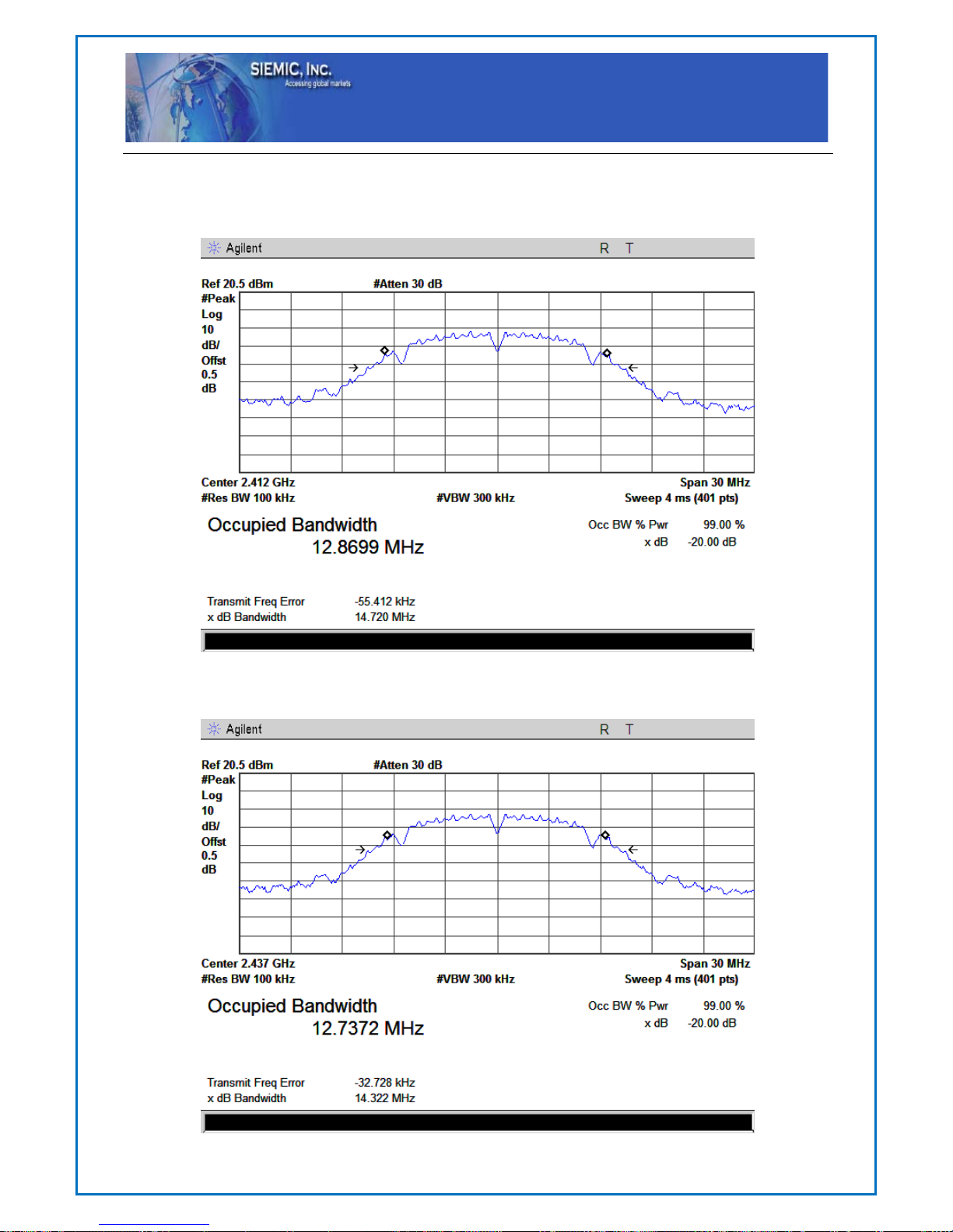
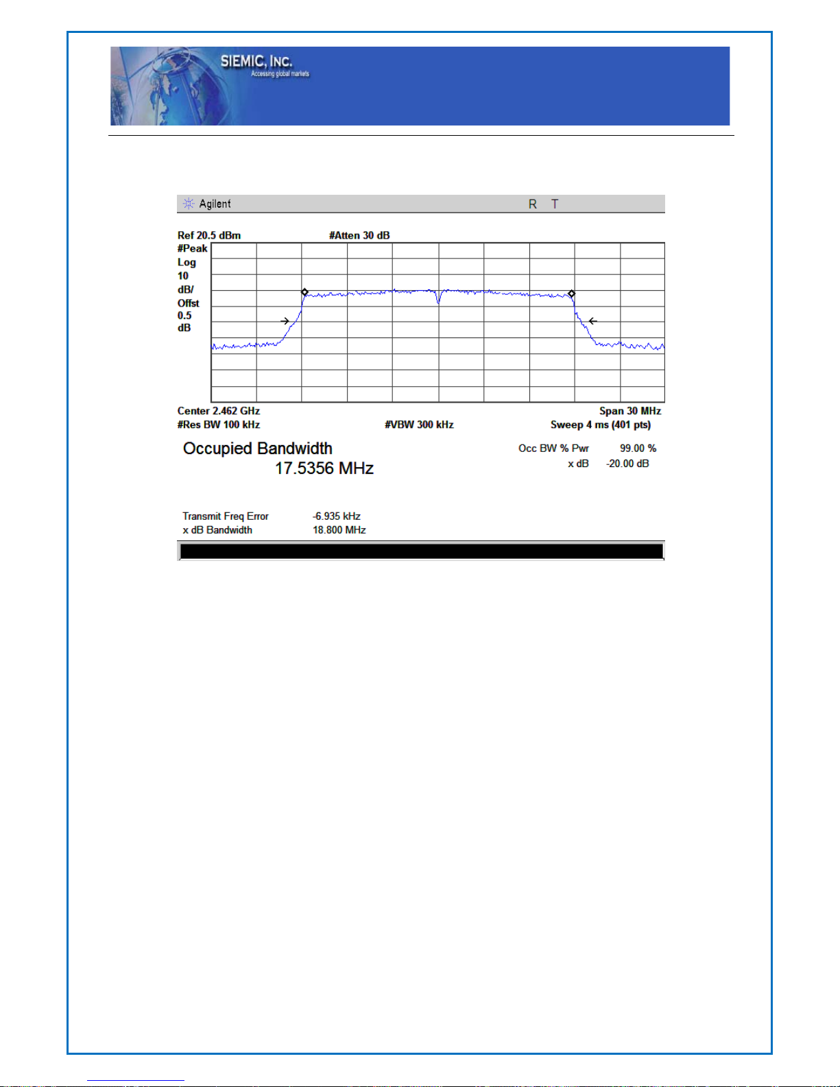
The 20dB bandwidth:
802.11b Low Channel
802.11b Middle Channel

Title: RF Test Report for 3G MOBILE PHONE
Main Model: AC4E
Serial Model: ANDY AC4E, AC4EW
To: FCC Part 15.247: 2013, ANSI C63.4: 2009
Report No.: 13070549-FCC-R3
Issue Date: December 06, 2013
Page: 18 of 74
www.siemic.com.cn
802.11b High Channel
802.11g Low Channel

Title: RF Test Report for 3G MOBILE PHONE
Main Model: AC4E
Serial Model: ANDY AC4E, AC4EW
To: FCC Part 15.247: 2013, ANSI C63.4: 2009
Report No.: 13070549-FCC-R3
Issue Date: December 06, 2013
Page: 19 of 74
www.siemic.com.cn
802.11g Middle Channel
802.11g High Channel

Title: RF Test Report for 3G MOBILE PHONE
Main Model: AC4E
Serial Model: ANDY AC4E, AC4EW
To: FCC Part 15.247: 2013, ANSI C63.4: 2009
Report No.: 13070549-FCC-R3
Issue Date: December 06, 2013
Page: 20 of 74
www.siemic.com.cn
802.11n Low Channel
802.11 Middle Channel
Title: RF Test Report for 3G MOBILE PHONE
Main Model: AC4E
Serial Model: ANDY AC4E, AC4EW
To: FCC Part 15.247: 2013, ANSI C63.4: 2009
Report No.: 13070549-FCC-R3
Issue Date: December 06, 2013
Page: 21 of 74
www.siemic.com.cn
802.11n High Channel

Title: RF Test Report for 3G MOBILE PHONE
Main Model: AC4E
Serial Model: ANDY AC4E, AC4EW
To: FCC Part 15.247: 2013, ANSI C63.4: 2009
Report No.: 13070549-FCC-R3
Issue Date: December 06, 2013
Page: 22 of 74
www.siemic.com.cn
5.4 §15.247(b) (3) - Conducted Maximum Output Power
1. Conducted Measurement
EUT was set for low, mid, high channel with modulated mode and highest RF output power.
The spectrum analyzer was connected to the antenna terminal.
2. Conducted Emissions Measurement Uncertainty
All test measurements carried out are traceable to national standards. The uncertainty of the measurement at
a confidence level of approximately 95% (in the case where distributions are normal), with a coverage factor
of 2, in the range 30MHz – 40GHz is ±1.5dB.
3. Environmental Conditions Temperature 24
o
C
Relative Humidity 45%
Atmospheric Pressure 1017mbar
4. Test date : November 26, 2013
Tested By : Back Huang
Standard Requirement:
Maximum Peak Conducted Output Power
The following procedures can be used to determine the maximum peak conducted output power of a DTS EUT.
Maximum Conducted Output Power
§15.247(b)(3) permits the maximum (average) conducted output power to be measured as an alternative to the maximum
peak conducted output power for demonstrating compliance to the limit. When these procedures are utilized, the power is
referenced to the emission bandwidth (EBW) rather than the DTS bandwidth (see Section 2.0 for definitions).
When using a spectrum/signal analyzer to perform these measurements, it must be capable of utilizing a number of
measurement points in each sweep that is greater than or equal to twice the span/RBW in order to ensure bin-to-bin spacing
of ≤ RBW/2 so that narrowband signals are not lost between frequency bins.
The ideal method for measuring the maximum (average) conducted output power is with the EUT is configured to transmit
continuously (duty cycle ≥ 98%) at its maximum power control level. However, when this condition cannot be realized,
video triggering or signal gating can be used to ensure that the measurements are performed only during periods when the
EUT is transmitting at its maximum power control level. An option is also provided that can be used when none of the
above requirements can be met with the available measurement instrumentation.
Procedures:
Maximum peak conducted output power:
Integrated band power method
This procedure may be used when the maximum available RBW of the measurement instrument is less than the DTS
bandwidth.
1. Set the RBW = 1 MHz.
2. Set the VBW ≥ 3 x RBW
3. Set the span ≥ 1.5 x DTS bandwidth.
4. Detector = peak.
5. Sweep time = auto couple.
6. Trace mode = max hold.
7. Allow trace to fully stabilize.
8. Use the instrument’s band/channel power measurement function with the band limits set equal to the DTS bandwidth
edges (for some instruments, this may require a manual override to select peak detector). If the instrument does not
have a band power function. sum the spectrum levels (in linear power units) at intervals equal to the RBW extending
across the DTS bandwidth.
Maximum conducted (average) output power:
Method AVGSA-1 (trace averaging with the EUT transmitting at full power throughout each sweep)
This procedure should be used with an RMS power averaging detector; however, a sample detector can be used when an
RMS detector is not available. This is the baseline method for measuring the maximum (average) conducted output power.
1. Set span to at least 1.5 times the OBW.
2. Set RBW = 1-5% of the OBW, not to exceed 1 MHz.
Title: RF Test Report for 3G MOBILE PHONE
Main Model: AC4E
Serial Model: ANDY AC4E, AC4EW
To: FCC Part 15.247: 2013, ANSI C63.4: 2009
Report No.: 13070549-FCC-R3
Issue Date: December 06, 2013
Page: 23 of 74
www.siemic.com.cn
3. Set VBW ≥ 3 x RBW.
4. Number of points in sweep ≥ 2 x span / RBW. (This gives bin-to-bin spacing ≤ RBW/2, so that narrowband signals
are not lost between frequency bins.)
5. Sweep time = auto.
6. Detector = RMS (i.e., power averaging), if available. Otherwise, use sample detector mode.
7. If transmit duty cycle < 98 %, use a sweep trigger with the level set to enable triggering only on full power pulses. The
transmitter shall operate at maximum power control level for the entire duration of every sweep. If the EUT transmits
continuously (i.e., with no off intervals) or at duty cycle ≥ 98 %, and if each transmission is entirely at the maximum
power control level, then the trigger shall be set to “free run”.
8. Trace average at least 100 traces in power averaging (i.e., RMS) mode.
9. Compute power by integrating the spectrum across the OBW of the signal using the instrument’s band power
measurement function, with band limits set equal to the OBW band edges. If the instrument does not have a band
power function, sum the spectrum levels (in power units) at intervals equal to the RBW extending across the entire
OBW of the spectrum.
Test Result: Pass.
Please refer to the following tables and plots.
The Peak Power
Channel
Channel
Frequency
(MHz)
Data Rate
(Mbps)
PK Output
Power
(dBm)
AV Output
Power
(dBm)
Limit
(dBm)
802.11b mode
Low 2412 1 11.06 8.16 30
Middle 2437 1 11.49 7.66 30
High 2462 1 11.97 7.20 30
802.11g mode
Low 2412 6 12.72 5.44 30
Middle 2437 6 12.31 4.83 30
High 2462 6 11.85 4.26 30
802.11n(20) mode
Low 2412 MCS0 10.41 4.83 30
Middle 2437 MCS0 10.23 4.56 30
High 2462 MCS0 9.66 4.07 30
 Loading...