

DDK HFC3000II Instruction Manual
S0140185-H
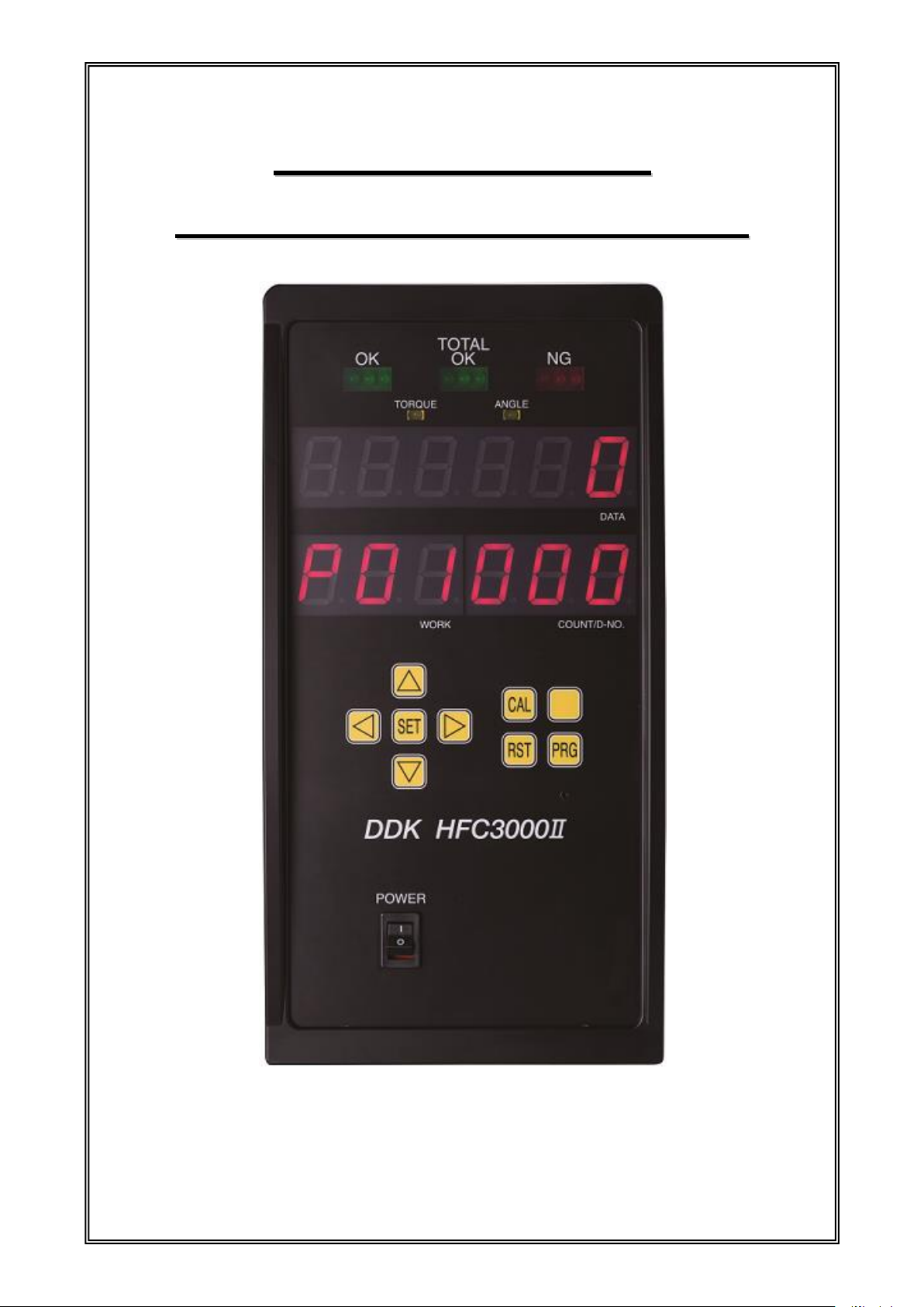
HHaannddhheelldd NNuuttrruunnnneerr
HHFFCC3300000
0
Ⅱ
Ⅱ
IInnssttrruuccttiioonn M
Maannuuaall
DDK
Original instructions
CCoovveer
r
S0140185-H

DAI-ICHI DENTSU LTD.
1-54-1 Shimoishihara, Choufu-city, Tokyo, 182-0034 Japan
TEL:+81-42-440-1465 FAX:+81-42-440-1436
URL:http://www.daiichi-dentsu.co.jp
E-mail:sales@daiichi-dentsu.co.jp
690-1 Ohmori, Kani-city, Gifu, 509-0238 Japan
TEL:+81-574-62-5865 FAX:+81-574-62-3523
S0140185-H
Copyright (C) 2014 DAI-ICHI DENTSU LTD. All Rights Reserved.

IInnttrroodduuccttiioonn
◆ It is important for you to read all “Safety Precautions” before using the equipment, and understand and observe
all instructions and recommendations included in this manual.
◆ Read all instructions and recommendations included in this manual, understand the functions and performance
of this nutrunner, and use this machine correctly.
◆ Wirings and parameter settings shall be conducted by a professional engineer.
◆ Indicate the following on all instruction manuals that use this equipment.
・This equipment is capable of high voltages hazardous to human life.
◆ Never conduct a withstand voltage test or megger test on this equipment.
For the safety of operator and equipment
Please confirm the following when unpacking this equipment.
◆ Confirm that you received the correct model that you had ordered.
◆ Confirm that there are no missing parts, accessories or tools. (Refer to the system structure
specification list.)
◆ Check for any damage caused during transportation.
Points to check when unpacking
Thank you for purchasing our Handheld Nutrunner.
This instruction manual describes the procedures for installation, and handling, and actions to
be taken in case of any failure.
◆ This instruction manual shall be delivered to the end user who operates the equipment.
◆ Read all instructions before use, and always keep this instruction manual with the equipment.
◆ Items not described in this instruction manual shall be considered “unavailable.”
◆ The product specification and appearance described in this instruction manual are subject to change without notice.
◆ All rights reserved. Any disclosure, copying, distribution, or use of the information contained herein is strictly
prohibited.
S0140185-H

Warranty Period
The warranty period of this equipment is 1 year from the date of purchase or the date
of delivery to the designated place.
Scope of Warranty
If a malfunction occurs in the equipment in the state of correct use in accordance with
this instruction manual within the warranty period, repair or replacement shall be
performed free of charge. However, accommodations shall be charged accordingly
in the following cases, even within the warranty period.
1. If the cause of a malfunction is a condition, environment, handling, etc., falling
outside that which is indicated in the instruction manual.
2. If a malfunction is due to a modification or repair performed by the customer.
3. If the cause of a malfunction is an apparatus other than this equipment.
4. If a malfunction is due to use outside the specification ranges of this equipment.
5. If the cause of a malfunction is an act of God or other disaster.
The scope of this warranty is limited to the main body of our equipment and damage
induced by a malfunction of this equipment shall be excluded from the warranty.
Warranty
Introduction
S0140185-H
SSaaffeettyy PPrreeccaauuttiioonns
s
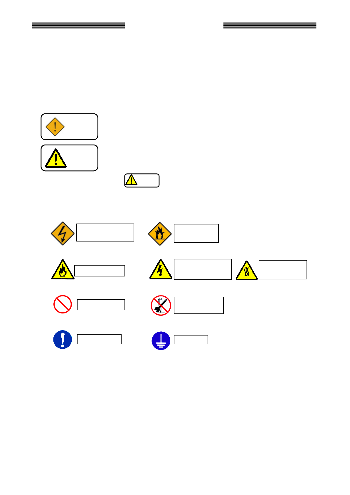
Warning
This symbol indicates that failure to observe instruction marked with
this symbol may result in severe personal injury or death.
This symbol indicates that failure to observe instruction marked with
this symbol may result in minor personal injury or material damage.
Warning:
Fire
Ground
Prohibited
Do not
disassemble
Required
Warning:
Electrical shock
Caution
Caution
Caution: Fire
Caution:
Electrical shock
Caution: High
Temperature
Read all instructions before operating the equipment in order to use this equipment safely and correctly.
Prior to use, read this instruction manual carefully and fully understand the equipment functions, safety
precautions and instructions.
Safety precautions in this manual are ranked as [Warning] or [Caution].
To prevent danger to the user and other persons as well as property damage, the instructions that must
be fully observed are marked with the symbols below.
◆ This instruction manual uses the following two symbols according to the degree of damage that may
be caused when the instruction is not observed.
Even instructions that are marked with may result in severe damage if they are not observed
according to conditions. Contents marked with the above symbols are very important instructions. For
your safety, follow all instructions marked with the symbols.
◆ This instruction manual uses various symbols for instructions that shall be observed.
S0140185-H
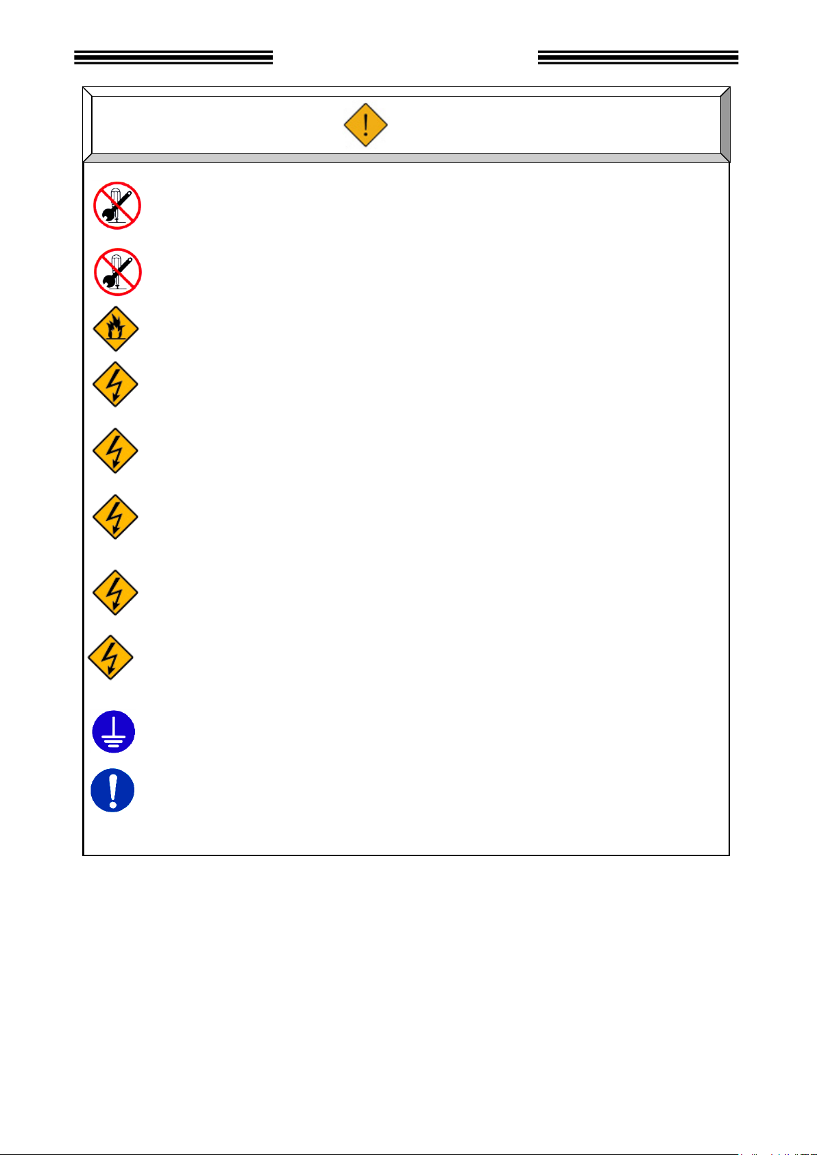
Do not remove the motors and gear cases of tools.
The tool output spindle may rotate and cause injury.
Do not repair, disassemble, or modify the equipment.
Failure to observe this instruction may cause injury, electric shock, fire, or malfunction.
Never operate the equipment where it is exposed to water or near corrosive atmosphere and
flammable gases. Failure to observe this instruction may cause fire.
Do not touch the connectors while the equipment is turned ON and for a while after the
equipment is turned OFF. Failure to observe this instruction may cause an electric shock.
Wiring operation and maintenance work shall be conducted by a professional engineer.
Failure to observe this instruction may cause an electric shock or injury.
Turn OFF the power when conducting wiring operation and maintenance and inspection.
Failure to observe this instruction may cause electric shock and injury.
Never damage the cables, apply excessive strength to cables, or squeeze the cables.
Never use damaged power cables.
Failure to observe this instruction may cause an electric shock or fire.
It takes 15 minutes for capacitor discharging. Do not touch the unit and terminals immediatey
after power off.
Be sure to conduct type-3 grounding for the FG terminals.
Failure to observe this instruction may cause electric shock.
In case of abnormal odor, noise, or operation error occurs, stop operation immediately
and turn OFF the power source.
Failure to observe this instruction may cause injury or fire.
Safety Precautions
Warning
S0140185-H
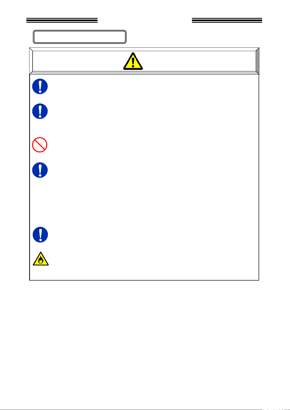
Transport the equipment properly according to its weight.
Failure to observe this instruction may cause injury and malfunction.
The conditions when transporting the equipment by ship are as below.
◆ Ambient temperature: -5°C ~ +55°C (Avoid freezing)
◆ Ambient humidity: 50% RH or lower (Avoid moisture)
◆ Package: Tight seal
Do not hold cables and output spindles when transporting the tools.
Failure to observe this instruction may cause injury or malfunction.
The equipment shall be stored under the following conditions.
◆ Ambient temperature: -5°C ~ +55°C (Avoid freezing)
◆ Ambient humidity: 90% RH or lower (Avoid moisture)
◆ Atmosphere: Indoors (Avoid direct sunlight)
No corrosive gases or flammable gases
No oil mist, dust, water, salt, iron powder
◆ Avoid direct vibration or shocks.
Failure to meet the above conditions may cause earth leakage and malfunction.
In case of disposal of the product, dispose of it as industrial waste.
This product has a built-in lithium battery.
Disposal method varies from region to region, so please follow the instructions properly.
It may cause short circuit, overheating, explosion, or ignition, resulting in injury or fire.
Caution
Transportation/Storage
Safety Precautions
S0140185-H
Installation/Wiring
Install the controller using the specified screws.
Failure to observe this instruction may cause malfunction.
Use the specified combination of the tool and the controller.
Failure to observe this instruction may cause fire and malfunction.
The power input parts must be provided with safety measures such as breakers and
circuit protectors.
Failure to observe this instruction may cause fire and malfunction.
Do not use a tool or a controller that has damages or missing parts.
Failure to observe this instruction may cause fire, injury, and malfunction.
Do not get on the top of equipment or place a heavy object on the top of equipment.
Failure to observe this instruction may cause injury, and malfunction.
Do not subject the equipment to excessive shock or impact.
Failure to observe this instruction may cause malfunction.
Provide proper and firm wiring.
Failure to observe this instruction may cause injury, fault, and malfunction.
Operate the equipment with the specified power supply voltage.
Failure to observe this instruction may cause injury, electric shock, fire, and malfunction.
When operating the equipment at a location such as the following, take sufficient measures to
shield the equipment.
◆Location where noise is generated
◆Location where the equipment is subjected to a strong electric field or magnetic field
◆Location a power wire is not laid nearby.
Failure to observe this instruction may cause injury, fault, and malfunction.
Caution
Safety Precautions
S0140185-H
Operation/Adjustment
Never operate the equipment with wet hands.
Failure to observe this instruction may cause electric shock.
Use the equipment under the following conditions.
◆Ambient temperature: 0°C~+45°C (Avoid freezing)
◆Ambient humidity: 90% RH or lower (Avoid moisture)
◆Atmosphere: Indoors (Avoid direct sunlight)
No corrosive gases or flammable gases
No oil mist, dust, water, salt, iron powder
◆Avoid direct vibration or shocks.
Failure to meet these conditions may cause earth leakage and malfunction.
Confirm and adjust all parameters before operation in order to prevent unexpected movement
of the equipment.
Failure to observe this instruction may cause an injury, malfunction, or fault.
Never conduct extreme adjustments or setting change that may cause instability of operation.
Failure to observe this instruction may cause an injury, malfunction, or fault.
Do not turn ON and OFF the equipment repeatedly. Failure to observe this instruction may
cause a malfunction.
Do not use the equipment at a torque higher than the maximum torque.
Failure to observe this instruction may shorten equipment life or cause breakage due to high
temperature caused by overload.
In case any abnormality occurs, remove the cause and ensure safety before resetting and
restarting the equipment.
Failure to observe this instruction may cause injury.
It is occurred reaction in sudden rise torque in the following cases.
Please attach the reaction jig.
Retightening bolt(nut) which already tighten.
Loosing bolt(nut) which already tighten.
Do not shut off the power while changing / setting each setting value.
The setting value may be damaged.
Caution
Safety Precautions
S0140185-H

Revision
date
Manual No.
Content of revision
Page
Aug, 2015
S0140185-A
1st Edition(Supporting V1.000)
Jan 2016
S0140185-B
Added explanation of various FB.
Updated the photograph of the base
Chapter 9
P3-3,4-4
May 2016
S0140185-C
Fixed a description of the RS232C
P4-20
Jun 2017
S0140185-D
Caution addition
24A Unit specification addition
I / O signal timing chart Precautionary note※4 corrected
Notes on cable connection corrected
Cable voltage corrected
Power supply voltage corrected
Storage of curves description corrected
Notes on NG Judgment (torque judgment) corrected
Notes on safety [operation / adjustment] added
Added M120 series tools.
P9-14
P2-2,2-4
P4-16
P1-6
P2-2
P5-2
P8-4
P6-26~27
Oct. 2017
S0140185-E
Notes on safety [Transportation / Storage] added
Added the Mounting Conditions to the Unit Outer Shape and Ins
tallation Dimensions
Added maximum length and relay number to tool cable specificat
ion
Backup power source corrected
P4-4
P4-6
P7-12
Oct. 2018
S0140185-F
[Notes on servo lock] added
[Notes on operation after fastening] added
[Gyro Setup Enable] corrected
[HFT-200M120-P1] tool added
P6-58
P6-58
P6-59,75
Appendix-3
Nov. 2018
S0140185-G
2-2-1 Delete Tool List
2-2-2 Added description about Analog monitor function
2-3 New Added Model
2-4-1 Changed description (5) Tool Type Checking Function
3-1-1 Changed description TOTAL-OK
3-1-2 Changed description of switch setting
3-1-3 New Added Bottom Panel SW1 Switch Settings
3-1-4 New Added Bottom Panel SW2 Switch Settings
4-5-1 Review function and usage description
New Added TB3-9 WORK SELECT BIT 5
New Added TB3-10 ID SELECT ENABLE
4-5-2 Review function and usage description
Added Notes on BANK SELECT
New Added TB2-2 CF WARNING
New Added TB2-3 BATCH SEQ END
4-5-4 Review description content
New Added TB3-9 WORK SELECT BIT 5
New Added TB3-10 ID SELECT ENABLE
New Added TB2-2 CF WARNING
New Added TB2-3 BATCH SEQ END
4-5-5 Fixed figure and caution statement
4-6-2 Fixed a circuit diagram.
6-4-2 Added display description when drive power is turned off
Rename No.9,10,14~17
New Added No.21~25
(Continued on next page)
P2-3
↑
P2-4
↑
P3-2
P3-3
P3-4
P3-5
P4-8,9
P4-9
↑
P4-10
↑
↑
↑
P4-12~21
P4-13
P4-15
P4-16
P4-17
P4-21,22
P4-24
P6-8
P6-9,10
P6-10
-
Revision History
(1/3)
S0140185-H

(2/3)
Revision date
Manual No.
Content of revision
Page
Nov. 2018
S0140185-G
(Continued from previous page)
6-4-3 New Added No.37
6-4-4 Change termination number of “COUNT / D-No.”
6-4-5 Change termination number of “COUNT / D-No.”
6-4-6 Added examples during a fastening operation
6-5-2 Change termination number of “COUNT / D-No.”
6-6 Delete CF card Format
6-7-2 Added action when rate increase angle is “0”
Change explanation of Break Away Torque Check
Added current value of motor type M120
Rename fastening parameters
D-No.520 [Full Scale Current Value] → [No Load Current Limit]
D-No.521 [Low Current Limit] → [Low Current Warning]
D-No.522 [High Current Limit] → [High Current Warning]
6-8-1 New Added SYS-030
New Added SYS-410~413
New Added SYS-504
Changed description SYS-035 *****1:Prohibition of Resume after Total Accept Relay
New Added SYS-035 ****1*:Initial Positon of Fastening Result Mode
New Added SYS-035 ***1**:Display Stop Status
New Added SYS-035 *1****:TB2-2_CF warning signal output
New Added SYS-035 1*****:Special Function 1
Changed description SYS-400
6-8-2 Changed description D-No.211
Rename fastening parameters
D-No.520 [Full Scale Current Value] → [No Load Current Limit]
D-No.521 [Low Current Limit] → [Low Current Warning]
D-No.522 [High Current Limit] → [High Current Warning]
New Added D-No.548~549
New Added D-No.589~599
Changed description D-No.209 Correction Angle
Changed description D-No.520,523
Added Notes on Recovery pulse operation
Added PLC I / O output signal to batch sequence program example
7-1 New Added A02(Unused), A07(Unused)
7-2-2 New Added A02(Unused)
7-2-3 New Added A.03-05 Watchdog Timer Error
7-2-7 New Added A07(Unused)
7-2-8 Change cause of A.08-02 Watchdog Timer Error
Delete A.08-06 Source Voltage Error
Change cause of A.08-07 Control Power Voltage Drop Error
A.08-08 Changed Over Speed to System Error
7-2-9 Added A.09-08 Reverse Torque Error
New Added A.09-13 Work Selection Error
7-4 Review items
8-1 Review document composition
8-1-6 Added LED lighting condition
8-3 Added How to change the extended RS232C port setting
New Added ID Data Input Setting
9-1-1 New Added ID SELECT ENABLE
New Added CF WARNING
New Added BATCH SEQ END
9-3-6 New Added System Area PLC Handshake
P6-11,13
P6-14
P6-15
P6-17
P6-21
P6-24
P6-33
P6-35
P6-36
↑
↑
↑
↑
P6-40,46
P6-42,53
P6-42,54
P6-47
↑
↑
↑
↑
P6-53
P6-55,68
P6-56
↑
↑
↑
P6-57,75
P6-57
P6-68
P6-73
P6-76
P6-81
P7-2
P7-4
↑
P7-6
↑
↑
↑
P7-7
P7-8
↑
P7-10
P8-2,3
P8-7
P8-9
P8-10~12
P9-2
P9-4
↑
P9-17
S0140185-H

(3/3)
Revision date
Manual No.
Content of revision
Page
Dec. 2018
S0140185-H
8th Edition(V1.309 compatible)
4-5-2 Delete the description of BATCH SEQ END, CF WARNING
4-5-4 (2) Delete the description of BATCH SEQ END, CF WARNING
6-9-1 (2) Changed the description of SYS-035 *1****.
9-1-1 (2) Changed the description of BATCH SEQ END, CF WARNING
P4-10
P4-16
P6-47
P9-5
S0140185-H

TTaabbllee ooff CCoonntteennttss
Chapter 1 Outline
1-1 How to Use This Instruction Manual 1-2
1-2 Outline of Functions 1-3
1-3 Usage Precautions 1-6
Chapter 2 Specifications
2-1 System Specifications 2-2
2-1-1 Duty Cycle Calculation 2-2
2-1-2 Unit Specifications 2-2
2-2 Performance 2-3
2-2-1 Fastening Performance 2-3
2-2-2 Controller Unit 2-3
2-3 Model 2-4
2-3-1 Controller Unit 2-4
2-3-2 Tools 2-4
2-4 Functions 2-4
2-4-1 Main Functions 2-4
2-4-2 Fastening Methods 2-5
Chapter 3 Part Names
3-1 Controller Unit 3-2
3-1-1 Controller Unit Front Panel 3-2
3-1-2 Controller Unit botton Panel 3-3
3-1-3 Bottom Panel SW1 Switch Settings 3-4
3-1-4 Bottom Panel SW2 Switch Settings 3-5
3-2 Tools 3-6
3-2-1 Angle Tool 3-6
3-2-2 Pistol Tool 3-7
Chapter 4 Installation
4-1 Installation Procedure 4-2
4-2 Unit Outer Shape and Installation Dimensions 4-3
4-3 Input Power Source Connection 4-5
4-4 Tool Cable Specifications 4-6
4-5 External Control Signal Connection 4-7
4-5-1 Controller Unit I/O Signals 4-8
4-5-2 Input Signal: BANK SELECT 4-9
4-5-3
Input and Output Circuit Specifications and Recommended Connection Circuit
4-5-4 Description of I/O Signals 4-12
4-5-5 Input/Output signal timing chart 4-21
4-6 External Monitoring Device Signal 4-23
4-6-1 External monitor signal specifications 4-23
4-6-2 Output Circuit 4-24
4-10
S0140185-H

Table of Contents
4-7 RS-232C Interface Signal 4-25
4-7-1 RS232C Specifications (RS232C-1) 4-25
4-7-2 RS232C Communication Specifications 4-25
4-7-3 Data Format (RS232C-1) 4-26
4-8 Ethernet Interface 4-28
Chapter 5: Power Activation and Operational Tests
5-1 Items to be Checked Before Power Activation 5-2
5-2 Items to be Checked When Activating the Equipment 5-3
5-3 Input Initial Setting Data 5-4
5-4 Items to be Checked After Activation 5-4
Chapter 6 Description of Operations
6-1 Controller Unit 6-2
6-2 Tool 6-4
6-3 Between RUN and PROGRAM Modes 6-5
6-4 RUN Mode 6-6
6-4-1 Changing Modes in the RUN Mode 6-7
6-4-2 Indications in the RUN Mode (Real Time Mode) 6-8
6-4-3 Indications in the RUN Mode (Fastening Result Mode) 6-11
6-4-4 Indications in the RUN Mode (Parameter Setting Mode) 6-14
6-4-5 Indications in the RUN Mode (System Setting Mode) 6-15
6-4-6 Indications in the RUN Mode (Operation View) 6-16
6-5 PROGRAM Mode 6-19
6-5-1 Changing Modes in the PROGRAM Mode 6-19
6-5-2 Indications in the PROGRAM Mode (Set Value Selection Mode) 6-20
6-5-3 Indications in the PROGRAM Mode (Set Value Editing Mode) 6-22
6-6 Copying of Parameters/Erasure of the Fastening Result Record 6-24
6-7 Fastening NG (Failure) Result Indications 6-26
6-7-1 Example of Fastening NG item indication 6-27
6-7-2 NG Judgment 6-29
6-8 Fastening Speed and Time 6-37
6-9 Parameter Structure 6-39
6-9-1 System Parameters 6-40
6-9-2 Fastening Parameters 6-55
S0140185-H
Chapter 7 Troubleshooting
7-1 Abnormal State Display 7-2
7-2 Abnormality Details/Causes and Recovery Methods 7-3
7-2-1 A.01:Torque Transducer Error 7-3
7-2-2 A.02:Unused 7-3
7-2-3 A.03:TOOL ID Error 7-4
7-2-4 A.04:System Memory Error 7-5
7-2-5 A.05:Servo Reply Error 7-5
7-2-6 A.06:Servo Type Error 7-6
7-2-7 A.07:Unused 7-6
7-2-8 A.08:Servo Amplifier Error 7-6
7-2-9 A.09:Setting Data Error 7-8

Table of Contents
7-3 Spindle Judgment: Checking the Contents of the REJECT 7-9
7-4 Ethernet Communication 7-10
7-5 RTC 7-12
Chapter 8 Options
8-1 CompactFlash 8-2
8-1-1 Summary 8-2
8-1-2 Selection criteria 8-3
8-1-3 CF ACCESS LED 8-3
8-1-4 Storing Data in the CF Card 8-4
8-1-5 Flow of Data Storage 8-5
8-1-6 Checking the capacity of the CF card 8-7
8-1-7 Formatting the CF Card 8-8
8-2 Expansion RS232C Interface 8-9
8-3 ID Data Input Setting 8-10
Chapter 9: External Interface
9-1 Common specifications 9-2
9-1-1 Fieldbus I/O signal specifications 9-2
9-1-2 Message Output Format (Handheld Tool Output → PLC Input) 9-6
9-1-3 Fieldbus Setup 9-8
9-2 EtherNet/IP 9-9
9-2-1 System Structure 9-9
9-2-2 Description of the hardware 9-10
9-2-3 I/O signal specifications 9-11
9-2-4 Fieldbus Setup 9-11
9-3 CC-Link 9-12
9-3-1 System Structure 9-12
9-3-2 Description of the hardware 9-13
9-3-3 I/O signal specifications 9-15
9-3-4 Fieldbus Setup 9-16
9-3-5 MELSEC-Q Series Parameter Setting 9-17
9-3-6 System Area PLC Handshake 9-18
9-4 PROFIBUS DP-V1 9-20
9-4-1 System Structure 9-20
9-4-2 Description of the hardware 9-21
9-4-3 I/O signal specifications 9-23
9-4-4 Fieldbus Setup 9-23
9-5 DeviceNet 9-24
9-5-1 System Structure 9-24
9-5-2 Description of the hardware 9-25
9-5-3 I/O signal specifications 9-27
9-5-4 Fieldbus Setup 9-27
9-6 PROFINET IO 9-28
9-6-1 System Structure 9-28
9-6-2 Description of the hardware 9-29
9-6-3 I/O signal specifications 9-30
9-6-4 Fieldbus Setup 9-31
S0140185-H

Table of Contents
Chapter 10 Warranty and Servicing
10-1 Warranty 10-2
10-1-1 Warranty Period 10-2
10-1-2 Scope of Warranty 10-2
10-1-3 Maintenance 10-2
10-2 Servicing System 10-3
Appendix: List of Tool Models
S0140185-H

Chapter 1 Outline
1
Chapter 1 Outline
S0140185-H
PAGE 1-1

Chapter 1 Outline
Chapter
Items
Contents
Chapter 1
Outline
Description of functions and precautions.
Chapter 2
Specifications
General specifications of the Hand System.
Chapter 3
Part Names
Names and functions of the respective parts of the Unit and
the tools.
Chapter 4
Installation
Installation procedure
Chapter 5
Power Activation and
Operational Tests
Items to be checked before power activation and procedures
for operational tests.
Chapter 6
Description of
Operations
Descriptions of items displayed on the panel and instructions
for setting the fastening set values.
Chapter 7
Troubleshooting
Descriptions of abnormal operation indications during
operation and corrective actions.
Chapter 8
Options
Optional functions
Chapter 9
External Interface
Fieldbus setting and functions
Chapter 10
Warranty and Servicing
Warranty period and servicing system
1-1. How to Use This Instruction Manual
This manual describes the system structure, specifications, handling method, etc., of the Handheld
Nutrunner System.
These are described in the following order in this manual:
PAGE 1-2
S0140185-H

Chapter 1 Outline
1-2. Outline of Functions
The Handheld Nutrunner is a flexible fastening tool equipped with a compact, high-performance
servomotor developed especially for this product. Like the usual high-performance nutrunner system, it
is designed to accommodate various tool models and provide useful functions for fool-proofing, data
management, data communication, etc.
☆ Compact Design
The Unit operates on single-phase 100V ~ 240V, making installation work related to the primary
power source easy.
☆ Screw Fastening
Screw fastening can be performed by the torque method or the angle method. An angle monitor
and a torque rate monitoring function are provided as functions for fool-proofing. Also, a fastening
counting function is interlocked with line control to prevent neglecting of fastening.
☆ Internal storage of 64 set value types
Full digitization was pursued to achieve volume reduction.
64 types of fastening set values can be input from the front panel and stored in the Unit.
Also, changing work (parameters) can be performed by external signals.
A backup battery is not used and there is thus no need to worry about problems such as battery
run-out, etc. (There is no need to worry about disappearance of the set values and other data).
☆ Data Communication
An RS-232C interface is incorporated to enable date communication with external devices.
A connector that enables communication with a PC with a dedicated software installed is provided
on the bottom. Connectors enabling sending of result data to a PLC or other external device are
provided on the bottom.
As an optional function, a D-NET, P-BUS or other fieldbus can be installed.
☆ Motor
Reduced equipment size and improved protection against dust and oil have been achieved by
adoption of a permanent magnet motor.
Also, accommodation of poor-condition environments has been made possible by adoption of a
resolver system.
☆ Preamplifier
Modularized high-precision torque signal amplification and transmission functions and a TOOL-ID
function are incorporated in the tools.
The weak signal of the torque transducer is amplified to minimize the effects of electrical noise, etc.,
on the signal.
☆ Self-Check Function
Each time a fastening operation starts, a calibration check of the torque transducer is performed to
check functions including those of the Unit and the cables to prevent abnormal fastening of bolt nuts,
tool breakage, etc.
☆ Abnormal Condition Display
S0140185-H
When an abnormality occurs, the corresponding abnormal state No. is displayed on the front panel.
PAGE 1-3

Chapter 1 Outline
Function Name
Automatic Save *1
Stored Data
User Console
Fastening
Data
Curve Data
Fastening Data
Setting Tab
Preferences
Auto Upload
Stored Data
Storage Content
Stored Data
Curve Data
Stored Data
Abnormals
Storage Location
PC
Each Controller
Storable Records
-
12000
results
500 results
Setting Item
Yes
No
JUDGMENT
ACCEPT
○
○ ○
REJECT
○
○ ○
ABNORMAL
○
○ ○ ○
BYPASS
○
○ ○
STOP
○
○ ○
RESET
STOP
○
○ ○
START OFF
○
○ ○
☆ Fastening Result Record
Fastening results data are saved in a nonvolatile memory (EEPROM) inside the Unit (approx. 10,000
sets of data). As curve record data, 100 sets of data are stored in the volatile memory (RAM) inside
the Unit.
As NG (failure) curve record data, 100 sets of data are stored in the nonvolatile memory (EEPROM).
The fastening results data and the NG (failure) curve data are therefore preserved even if the power
is turned off. However, once the power is turned off, the curve record data are initialized and the
previous data are lost when the power is turned on subsequently. The above data can be read with
the User Console software.
●Fastening Result Storage Feature List of HFC3000 System
*1:During the data collection in the Fastening Data screen of HFC3000 User Console,
Automatic Save is enabled.
S0140185-H
PAGE 1-4

Chapter 1 Outline
Function Name
Stored Curve Data
CF Card *2
User Console
Stored Curve Data
-
Storage Content
Stored Curve
Data *3
Stored Reject
Curve Data
Stored
Data
Curve Data
Storage Location
Each Controller
CF Card
Storable Records
100 results
-
-
Storage Format
Torque-Angle (540deg)
-
Torque-Angle (180deg)
JUDGMENT
ACCEPT
○
○ ○
REJECT
○
○ ○ ○
ABNORMAL
○
○ ○ ○
BYPASS
○
○ ○
STOP
○
○ ○ ○
RESET
STOP
○
○ ○
START OFF
○
○ ○ ○
*2:CF CARD Option and CF CARD are required separately.
*3:The stored contents (curve data) will be cleared when the control power of the Unit is turned OFF.
S0140185-H
PAGE 1-5

Chapter 1 Outline
1-3. Usage Precautions
To ensure use in the best conditions, please conform to the following instructions.
☆ Handling of tool
Each tool is designed to fully withstand vibrations and shocks that may be generated during ordinary
fastening operation. However, it cannot bear a strong impact that may occur when the tool is
dropped or collides against another tool (there is a possibility of breakage of the tool).
Please be very careful in handling the tools.
☆ Fastening
Avoid fastening at a torque exceeding the maximum fastening torque of a tool. Also, even when
the maximum fastening torque is not exceeded, use the tool within the prescribed duty cycle
(ratio of rotating time and downtime).
☆ Cable Connection
To supply power to the Unit, use a cable conforming to the specification (dedicated cable).
Lock the connector of the tool connection cable securely.
*Ground the Unit without fail. Otherwise, there is danger of fault or electric shock.
The accessory power cable is for use at 125V AC. Exchange the plug if use is to be made at 200V
AC. Supply the primary power using wiring of no less than 1.25mm2. If the power is supplied using
a thin wiring, the power source voltage may drop to 80V AC or less and a Source Voltageply Error
may occur.
☆ Installation Environment
The following locations can be a cause of fault or malfunction. Avoid such locations or take
measures such as installing a forced cooling device, etc.
◆ A location exposed to direct sunlight or a location where the ambient temperature falls outside
the range of 0°C to 45°C.
◆ A location where the relative humidity falls outside the range of 20% to 90% or a location where
the temperature changes rapidly and dew condensation occurs.
The equipment cannot be used at the following locations (if there is a possibility for use at any of the
following locations, please contact the manufacturer).
◆ A location with a high amount of iron powder or other conductive powder, oil mist, salt, or
organic solvent
◆ A location with corrosive gas or flammable gas
◆ A location where a strong electric field or a strong magnetic field is generated
◆ A location where the Unit and the tools are directly subjected to strong vibration or shock
☆ Static Electricity
Since the Unit is composed of many electronic components, please be aware of static electricity.
Excessive static electricity may occur at dry locations, therefore we recommend the operator to
touch grounded metals before operating the front panel operation switches to discharge the static
electricity charged inside the human body.
☆ Cleaning
Never use thinner or other organic solvent to clean the external surfaces of the Unit or a tool. An
organic solvent may melt the surface coating or penetrate inside and cause damage.
Lightly wipe off dirt with a cloth dampened with alcohol or warm water.
☆ Noise
S0140185-H
The Unit is made up of electronic components – therefore, make sure there is no equipment that will
generate strong noise in the surroundings.
Make sure that the cables that connect the Unit and the tool are not placed inside a duct, etc.,
together with a power source line or other wiring.
PAGE 1-6

Chapter 2 Specifications
2
Chapter 2 Specifications
S0140185-H
PAGE 2-1

Chapter 2 Specifications
Power
Source
Voltage
Single-phase 100 to 240V AC ±10%
(5m cable for 125V AC provided as accessory)
Frequency
50/60Hz
Installation environment
No vibration must be applied directly to the Unit.
Forced-cooling equipment or heating equipment is required when
using the Unit outside the following operating range.
Operating
Conditions
Ambient
temperature
0°C to +45°C (Avoid freezing)
Ambient
humidity
No more than 90%RH (Avoid condensation)
Operation
range
Duty cycle: within 50% (within the prescribed time for one cycle)
See “2-1-1 Duty Cycle Calculation.”
Storage
Conditions
Ambient
temperature
-5°C to +55°C (Avoid freezing)
Ambient
humidity
No more than 90%RH (Avoid condensation)
Shipping
Conditions
Ambient
temperature
-5°C to +55°C (Avoid freezing)
Ambient
humidity
No more than 50%RH (Avoid condensation)
Packing
method
Tight seal
Ambience
Indoors (no direct sunlight), free from corrosive gas, flammable
gas, oil mist, dust, and dirt.
Unit model
HFC-B016
HFC-B024A
Motor model
M50,M80
M50,M80,M120
Power source voltage
Single phase 100 to 240V AC ±10%
Power source frequency
Both 50/60HZ
Power consumption rating
80W
120W
Maximum momentary current
11.3Ap
(at the time of motor max power)
19Ap
(at the time of motor max power)
Inrush current
38Ap/AC100V,76Ap/AC200V
Power supply capacity
1.2kVA
1.9kVA
Ground fault interrupter
(Sensitivity electric current)
⊿I 30mA Max
2-1. System Specifications
2-1-1. Duty Cycle Calculation
The duty cycle for HFC series is calculated as follows.
Duty Cycle (%) = Rotating time ÷ (Rotating time + Downtime) × 100
2-1-2. Unit Specifications
S0140185-H
PAGE 2-2

Chapter 2 Specifications
Torque precision
From 1/2 to Calibration torque
3σ/:
X
5% or less
From 1/4 to 1/2 Calibration torque
3σ/
X
: 6% or less
(Precisions in case of in-house standard fastening.
*May differ according to work.)
Angle display minimm unit
0.1 degree
Angle internal control unit
0.1 degree
Torque transducer accuracy
±1% of full scale
Torque transducer linearity
±0.5% of full scale
Fastening method
Torque method/Angle method
Torque rate setting
3
CPU
32-bit RISC
Data communication
・ETHERNET :1 port
・RS232C :1 port (Optional addition of 1 port)
・Fieldbus :1 port (Option)
DEVICENET, PROFIBUS-DP V1, CC-Link, etc.
Analog monitor function
·Torque
·Angle pulse
·Current
·Rotational speed
·Direction of rotation
2-2. Performance
2-2-1. Fastening Performance
2-2-2. Controller Unit
S0140185-H
PAGE 2-3

Chapter 2 Specifications
2-3. Model
2-3-1. Controller Unit
HFC-B0**-*-*-*-*
N:Option4 nothing EN:EtherNet
N:Option3 nothing CF:CF Card(RS232C-2)
N:Option2 nothing IO:I/O terminal is attached
N:Option1 nothing CC:CC-Link DN:DeviceNet
PB:ProfiBusDPV1 PI:ProfiNetIO EI:EtherNetI/P
16:16A 24A:24A
2-3-2. Tools
Please refer to the appendix.
2-4. Functions
2-4-1. Main Functions
(1) Fastening Function
The HAND SYSTEM is capable of the following fastening methods.
1. Torque method: Angle monitor, Torque rate monitor, 1/2/3 step fastening
2. Angle method: Torque monitor, Torque rate monitor, 1/2/3 step fastening
(2) Self-Check Function
When the start lever is gripped (turned ON), the home-position voltage level and CAL voltage level
of the torque transducer are automatically checked before fastening. This function is useful for
checking the transducer for abnormality and checking the cable for breakage etc.
(3) Bypass Function
When the BYPASS signal is input, the BYPASS signal is output to notify that the Unit is in the
BYPASS mode. Starting by the START signal cannot be performed in this mode.
If the Unit enters the BYPASS mode during fastening, fastening is stopped immediately.
(4) Abnormal Signal Output Function
When a fastening failure (NG) or a system error occurs, the tool is stopped immediately and a
signal corresponding to the problem is output. Also, the fastening failure (NG) details and the
abnormal state No. are displayed on the Unit front panel.
(5) Tool Type Checking Function
The tool model set at the unit and the tool model that is presently connected are compared when
power on or tool replacement is performed. If the tool models differ, the abnormal state number [Tool
Type Error] is generated.
S0140185-H
PAGE 2-4
Chapter 2 Specifications
2-4-2. Fastening Method
(1) Torque Method (Angle Monitor)
Fastening is performed up to a preset standard torque.
The fastening operation is performed with the preset torque as the target, and high limit/low limit
judgment of the angle value is enabled.
The number of fastenings steps is selectable among 1 step, 2 steps, and 3 steps.
(2) Angle Method (Torque Monitor)
Fastening is performed up to a preset standard angle.
The fastening operation is performed with the preset angle as the target, and high limit/low limit
judgment of the torque value is enabled.
Generally when a handheld tool is used, the angular precision may vary according to the state in
which the tool is held during fastening. Use in combination with the reaction force receiver jig etc.,
is recommended.
The number of fastenings steps is selectable among 1 step, 2 steps, and 3 steps.
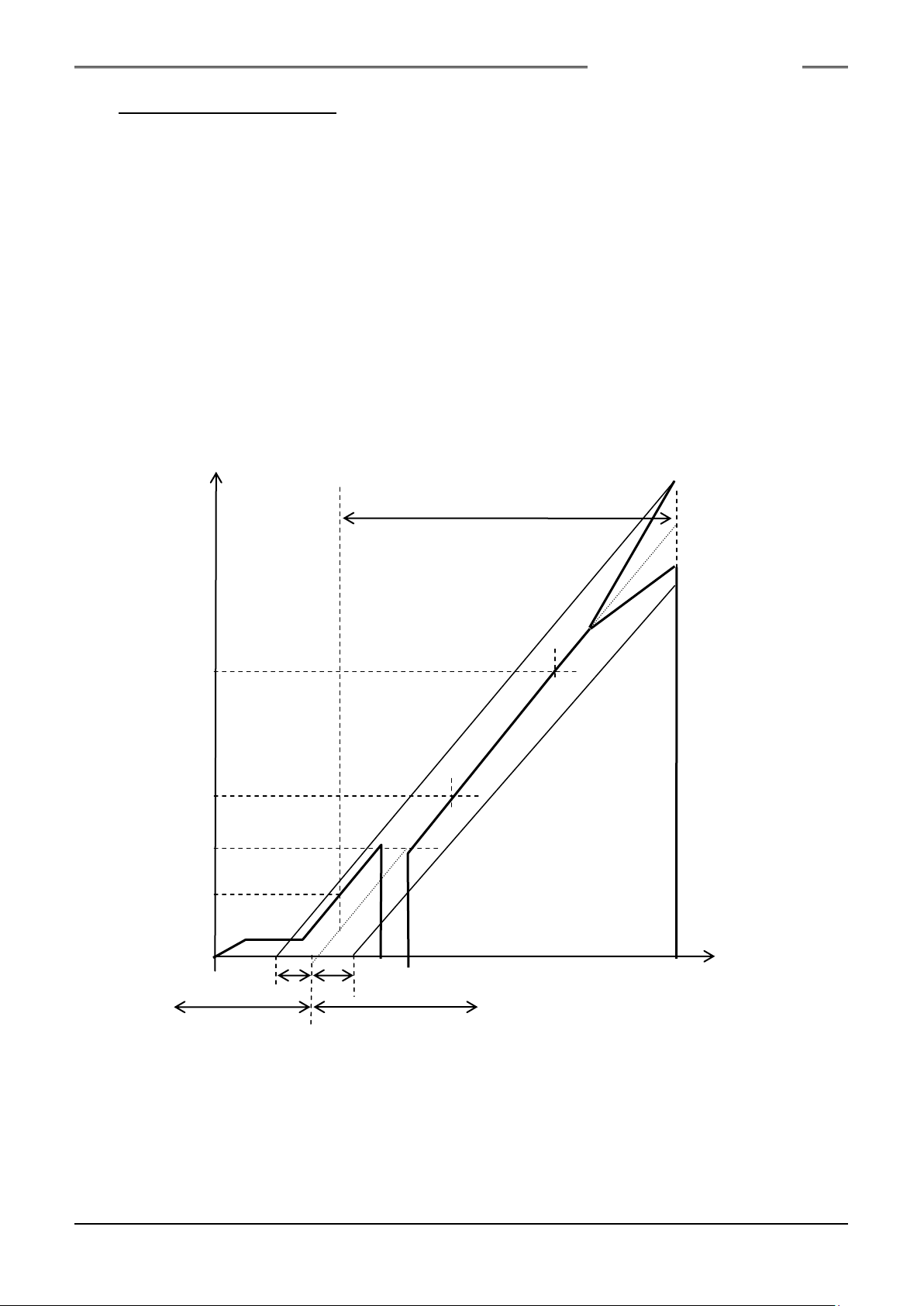
(3) Differential Angle Check Method
Torque
Standard Angle
Rate 2 End Torque
Rate 2 Start Torque
1st Torque
Snug Torque
Differential Angle (fastening result) Angle
Differential Low Limit (-) Angle Differential High Limit (+) Angle
Seating point calculated from the value of rate 2
Fastening is performed from the Snug torque (angle measurement start torque) to the standard
angle value (or the standard torque value).
After completion of fastening, the seating point is calculated from the value of rate 2.
The differential angle is then calculated from the final torque value and the value of rate 2, and
judgment is performed if differential angle check is available.
The rate 2 is calculated from the rate 2 start torque and the rate 2 end torque.
S0140185-H
PAGE 2-5

Chapter 2 Specifications
Memo
S0140185-H
PAGE 2-6

3
Chapter 3 Part Names
Chapter 3 Part Names
S0140185-H
PAGE 3-1
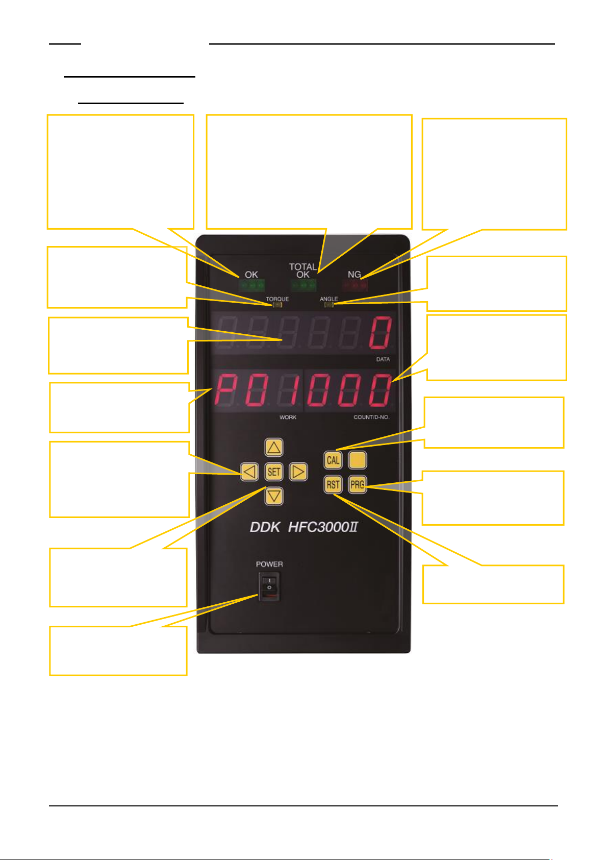
Chapter 3 Part Names
POWER
Controller main power
switch
CAL
Manual calibration check
pushbutton
RST
Reset pushbutton
PRG
Program mode select
pushbutton
SET
Switch for finalizing a
change of data
◁▷▵▿
Selection switches for
WORK, parameter, and
data setting.
NG (REJECT)
Lights up when even one
of the preset judgment
criteria is not met by the
fastening results.
ANGLE
Lit up in the fastening
angle result display
TORQUE
Lit up in the fastening
torque result display
mode.
6-dight 7-segment LED
Displays a set value,
fastening result, or other
data.
3-dight 7-segment LED
Displays the WORK No.
(parameter).
3-digit 7-segment LED
COUNT/D-No.
Displays the cycle count
and the data No.
TOTAL OK
Lights up when acceptable (OK) Turns
on when fastening results are obtained
for the designated number of times. and
turns off when the batch reset input
signal is ON.
Flashing a patch sequence operation is
finished
OK (ACCEPT)
Lights up when the fastening
results are within the
standard value ranges of all
preset judgment criteria, and
flashes while TOTAL OK is
ON.
3-1. Controller Unit
3-1-1. Front Panel
S0140185-H
PAGE 3-2
 Loading...