

DDK CM10-AP2S-M, CM10-AP2S-L, CM10-AP2S-LD6, CM10-AP2S-SD6, CM10-AP2S-MD6 Assembly Manual
...
CM10-AP××S-×(D6)
Angle Plug Connector
(Weight saving typeCrimp Type)
Cable Assembly Manual(Standard Type)
Date of Issue: February 16, 2009
Material No. TC-604
DDK Ltd.
2ND Production engineering department assembly group
14 Matsuyama-cho, Moka-shi, Tochigi
TEL : 0285-82-4463
No.
’08.3.26
’08.5.13 No.T-2205
Revision Date Revision No.
C 16/02/09 New Issue

Material No. Page
TC-604 1/11
Contents
Page
1.
Outline................................................................................................................................................. 2
2. Specifications...................................................................................................................................... 2
2-1. Applicable connector .................................................................................................................. 2
3. Cable Assembly Process .................................................................................................................... 2
3-1. Cutting a cable............................................................................................................................ 2
3-2. Stripping a cable sheath ............................................................................................................. 2
3-3. Inserting parts ............................................................................................................................. 3
3-4. Stripping a core wire ................................................................................................................... 3
3-5. Crimping a contact...................................................................................................................... 4
3-6. Inserting a contact ...................................................................................................................... 5
3-7. Tightening an angle back shell ................................................................................................... 6
3-8. Inserting a bushing and a cable clamp ....................................................................................... 8
3-9. Tightening a clamp nut ............................................................................................................... 9
Material No. Page
TC-604 2/11
1. Outline
This Cable Assembly Manual explains how to assemble the wire to the CM 10 angle plug connector.
(Crimp Type)
2. Specifications
2-1. Applicable connector
Connector name Drawing number
CM10-AP2S-S(D6) 115J-AP12162-1
CM10-AP2S-M(D6) 115J-AP12162-2
CM10-AP2S-L(D6) 115J-AP12162-3
CM10-AP10S-S(D6) 115J-AP12160-1
CM10-AP10S-M(D6) 115J-AP12160-2
CM10-AP10S-L(D6) 115J-AP12160-3
3. Cable Assembly Process
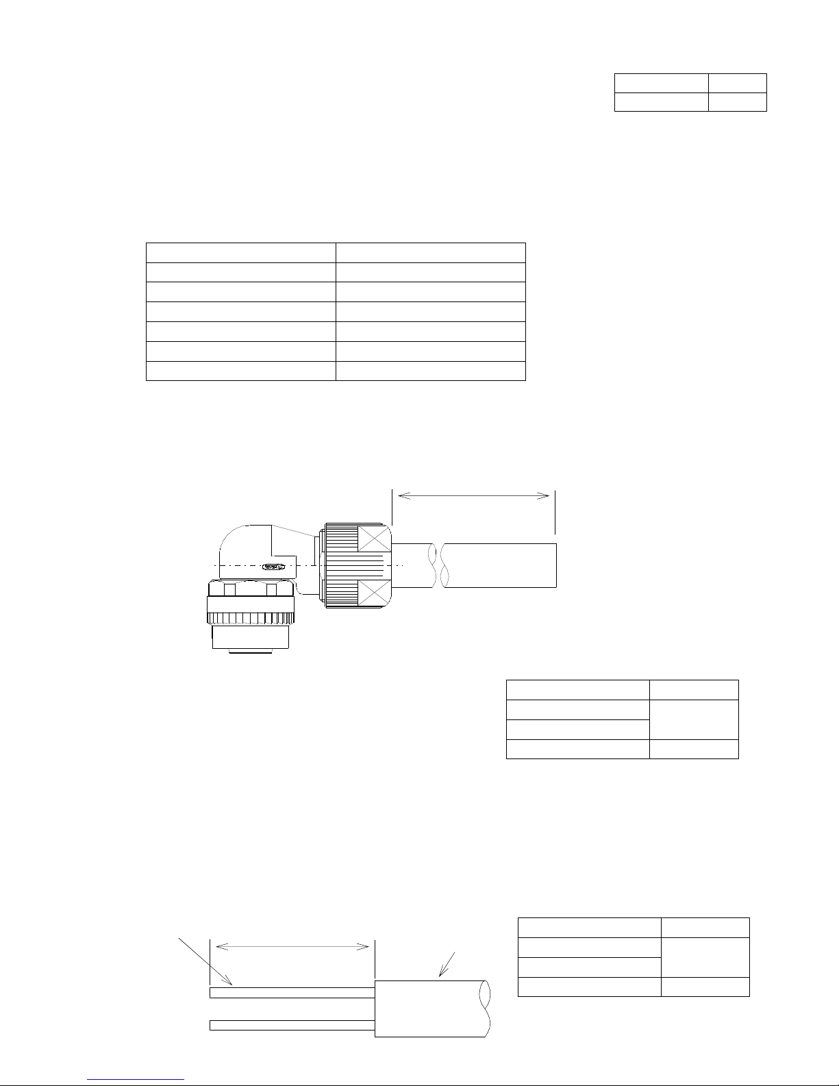
3-1. Cutting a cable
Cut the cable to the following dimensions:
Note! Not to change cable length.
3-2. Stripping a cable sheath
Strip the cable sheath to the length A as shown below.
Note! Take care the cable peel length.
Take care not to damage anything.
* When making CM10-AP10S(D6), strip the cable for No. 10 terminal in a way that makes the A
length 1mm longer than other cables. (To avoid the cable tension when inserting a contact to
the housing in a later process.)
Product name A length
CM10-AP XX S-S(D6)
CM10-APXX S-M(D6)
30±0.5mm
CM10-AP XX S-L(D6) 45±0.5mm
A
(A+1mm for No. 10 terminal only)
Cable core
Sheath
*Cable length after cutting = measurement A for CM10-AP××S (D6)+ Cable length
= A + Cable length
Product name A length
CM10-AP XX S-S(D6)
CM10-APXX S-M(D6)
40±0.5mm
CM10-AP XX S-L(D6) 55±0.5mm
Cable length
Material No. Page
TC-604 3/11
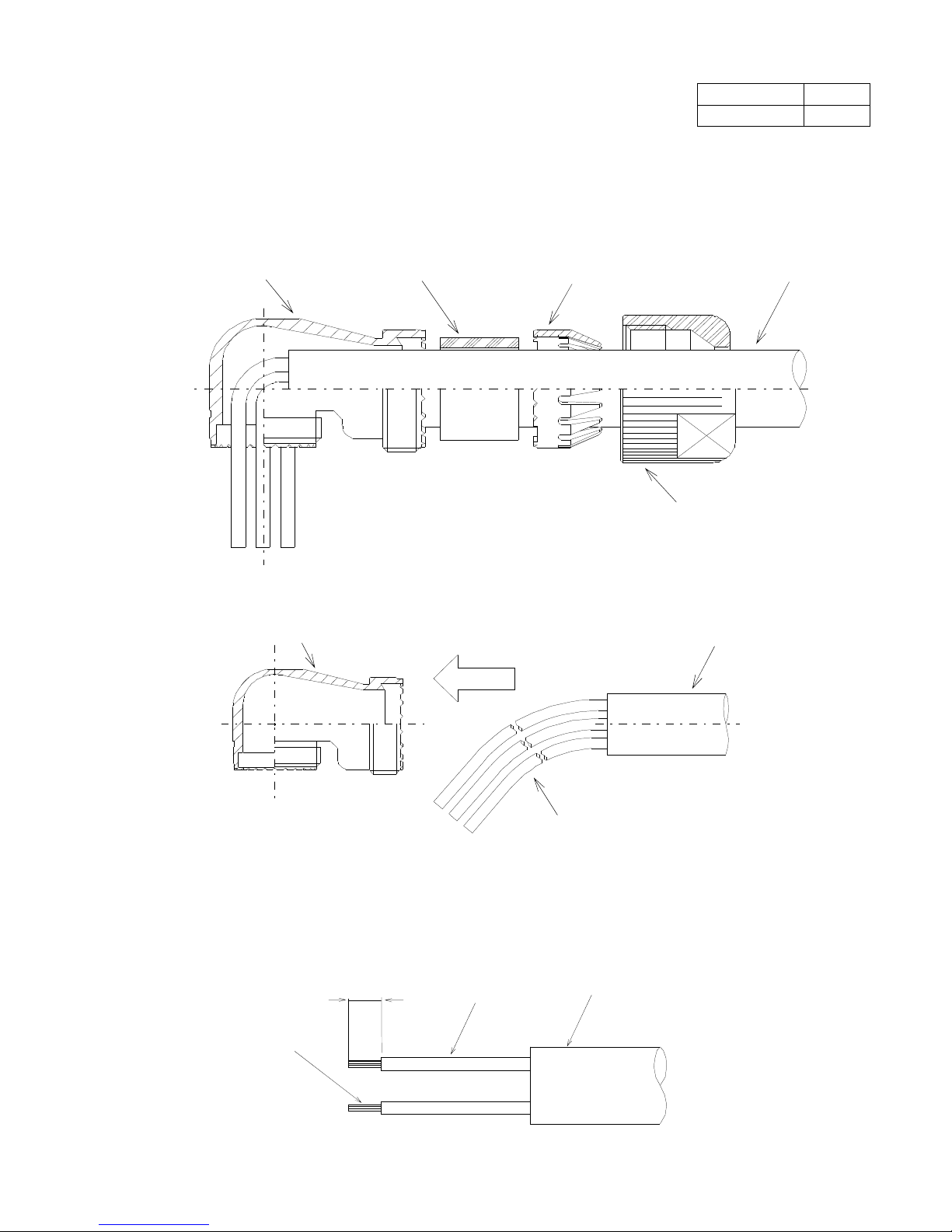
3-3. Inserting parts
Insert the clamp nut, the cable clamp, the bushing and the angle back shell to the cable stripped.
Note! Pay attention to the direction each part is inserted.
Make sure that every part is inserted.
* To insert the angle back shell, bend the cable.
3-4. Stripping a core wire
Strip the cable’s core wire to the length 3.0 to 3.5mm.
Note! Do not mistake the length of the core wire to be stripped.
Do not leave cut or scratch to the cable core.
Bushing
Cable clamp
Clamp nut
Angle back shell
Cable
Insert
Cable
Bend
Angle back shell
Sheath
Core wire
3.0 to 3.5
Cable core
 Loading...