

Page 1
0
EN 160518
Installation and User manual
Models LEADER and LEADER TWIN
Firmware 160518 and later
ENGLISH
Tr ans lati on of D utch o rig inal
Page 2

1
EN 160518
Contents
1 Introduction .................................................................................................................................... 3
2 Product details ................................................................................................................................ 4
2.1 Specifications dddrop leader/leader twin .............................................................................. 4
2.2 Printer overview ...................................................................................................................... 5
3 Installation of the device ................................................................................................................ 6
3.1 Placing the device ................................................................................................................... 6
3.2 Removing transport locks ....................................................................................................... 6
3.3 Connecting power ................................................................................................................... 7
4 Use of the device ............................................................................................................................ 8
4.1 Info screen .............................................................................................................................. 8
4.2 Menu structure BEFORE printing ............................................................................................ 9
4.3 Main menu BEFORE print job ............................................................................................... 10
4.3.1 Prepare menu ............................................................................................................... 11
4.3.2 Change filament (BEFORE a print job) .......................................................................... 12
4.3.3 Print from SD ................................................................................................................. 13
4.3.4 Firmware version .......................................................................................................... 13
4.4 Menu structure DURING a print job ..................................................................................... 14
4.5 Main menu DURING a print job ............................................................................................ 14
4.5.1 Advanced menu ............................................................................................................ 15
4.5.2 Change filament (DURING a print job) .......................................................................... 16
5 Slic3r .............................................................................................................................................. 17
5.1 Slic3r Install ........................................................................................................................... 17
5.2 Exploring Slic3r ...................................................................................................................... 19
5.2.1 Plater ............................................................................................................................. 19
5.2.2 Print Settings ................................................................................................................. 21
5.2.3 Filament Settings........................................................................................................... 22
5.2.4 Printer Settings.............................................................................................................. 23
5.3 Generating a G-code ............................................................................................................. 24
6 First print ....................................................................................................................................... 25
6.1 Preparation of material ......................................................................................................... 25
6.2 Preparing heated bed ........................................................................................................... 25
6.3 Preparation of G-code ........................................................................................................... 26
6.4 Start Print .............................................................................................................................. 26
Page 3

2
EN 160518
6.5 Taking out the printed model ............................................................................................... 26
7 Maintenance ................................................................................................................................. 27
7.1 Adjusting heated bed ............................................................................................................ 28
7.2 Empty the container ............................................................................................................. 30
7.3 Cleaning the brush ................................................................................................................ 30
7.4 Adjusting bed to nozzle distance (major adjustments only!) ............................................... 30
8 Safety and Conformity .................................................................................................................. 31
8.1 Electromagnetic compatibility (EMC) ................................................................................... 31
8.2 Electrical safety ..................................................................................................................... 31
8.3 Mechanical safety ................................................................................................................. 31
8.4 Risk of burn ........................................................................................................................... 31
8.5 Health .................................................................................................................................... 31
8.6 General note on safety ......................................................................................................... 31
A product of:
IF-Adamas B.V.
Transportweg 17
7007 CL Doetinchem
The Netherlands
info@if-adamas.com
Page 4
3
EN 160518
1 Introduction
This manual covers the necessary steps needed to get the best results from your dddrop printer. The
manual covers Installation, Use, Maintenance and Issues. It is possible that you already have
experience with other versions of dddrop 3D printers. It is however recommended to study this
manual thoroughly in order to understand the latest procedures related with the use of the dddrop
LEADER and LEADER TWIN 3D-printers.
In chapter 2 the product specifications are given of the dddrop LEADER/LEADER TWIN together with
an overview of the machine. In chapter 3 the installation of the printer is described followed by its
use in chapter 4. Chapter 5 is dedicated to the installation and use of Slic3r. Chapter 6 covers the
procedure on how a print is started. Additionally, chapters Maintenance and Safety are found in
chapters 7 and 8 respectively.
Figure 1. Quick start Steps
Following the quick start steps above, the manual guides you step by step through the procedures.
Information that requires extra attention is presented in the following format:
WARNING
A warning is given when the concerning procedure may cause harm or injury to the user, or
damage to the machine. A warning precedes the section it relates to.
Installation
• Positioning
• Connecting the power supply
Use
• Display and menu
• Slic3r installation
• Slic3r walkthrough
First print
• Print order preparation
• Starting a prepared print order
Page 5

4
EN 160518
2 Product details
2.1 Specifications dddrop leader/leader twin
Printing
Physical dimensions
Print method
Fused Filament
Fabrication (FFF)
Frame dimensions
X 530 mm
Y 555 mm
Z 570 mm
Print volume
320 x 310 x 305 mm
With material
X 530 mm
Y 660 mm
Z 570 mm
Layer thickness
0,01-0,4 mm (*)
Filament diameter
1,75 mm
Mass
± 30 kg
Nozzle diameter
0,4 mm (**)
Total transport mass
35 Kg
Print speed
Max. 150 mm/s
Software
Temperature
Slicer software
Silc3r – dddrop config
Environment temperature
15 – 30 °C
File types
STL/OBJ/AMF
Nozzle temperature range
150 – 300 °C
OS supported
Windows
Mac OS X
GNU Linux
Heated bed temperature
range
50 – 130 °C
Power/connectivity
Sound
Power
100-240VAC / 47-63Hz
600 watt max.
Average sound level (in
use)
<55 dB(A)
Connectivity
Stand-alone printing
through SD-card
USB (firmware)
(*) Standard settings with standard nozzle included (0.25mmlayer thickness, 0.4mm nozzle), possibly smaller nozzles are
required for reduced layer thicknesses, please contact your supplier.
(**) Other nozzle diameters (e.g. 0.2mm, 0.4mm, 0.6mm or 0.8mm) are optional, please contact your supplier.
Page 6
5
EN 160518
2.2 Printer overview
Figure 2. Printer overview (dddrop leader twin)
Page 7
6
EN 160518
3 Installation of the device
In this chapter the installation of the dddrop LEADER and dddrop LEADER TWIN 3D printers is
described. These steps have to be made before use. The first step is placing the machine on a stable
support, followed by the power connection to the mains.
WARNING
The machine is to be lifted and moved by two persons using the 4 grips on both sides of the
machine in order to minimize the chance of pinching or dropping of the device. Place the machine
on a stable support with a loading capacity of at least 50kg.
WARNING
The machine is to be used in well ventilated areas only. Fumes that can occur during the printing
process are material dependent and, especially in case of insufficient ventilation, have to be
extracted.
3.1 Placing the device
The dddrop printer is supplied with the SD-card in the printer, this manual and a power cable.
Accessories like Quick Starting kits can be ordered additionally enabling the user to start right away.
The machine needs to be placed on a stable support with a loading capacity of at least 50kg in a well
ventilated area, free of weather influences, limited humidity and at room temperature.
WARNING
The machine is shipped with transport locks which have to be removed before the machine is
connected to the mains and put to use. Failure to remove the transport locks may cause damage
to machine components beyond repair.
3.2 Removing transport locks
The printer is shipped with 4 transport locks made from foam tubing. The transport locks eliminate
movability of the extruder in X and Y directions during transportation. These transport locks have to
be removed by a simple pull action in order to separate them from the guides they cover. Failure to
do so may cause damage to machine components beyond repair. No tools are needed.
WARNING
Only use the power cable provided when connecting the machine to the mains. Use a grounded
wall plug. Ensure that during maintenance the machine is turned OFF (O) and the mains cable is
detached.
WARNING
Before connecting your machine, ensure that the power switch is switched OFF (O) before
connecting the power cable to the mains. The machine can be turned off AT ANY TIME by
switching the power switch from ON (I) to OFF (O). It is however strongly recommenced to only
switch the machine OFF when it is not in use.
Page 8
7
EN 160518
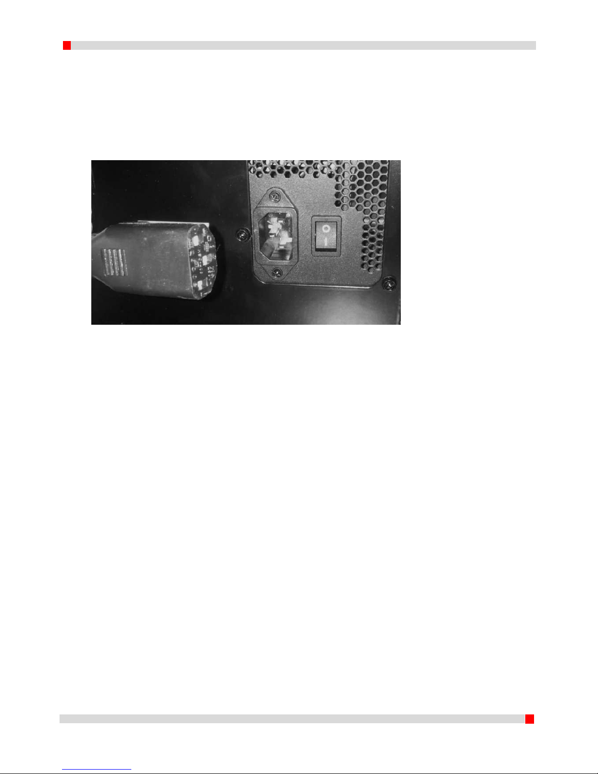
3.3 Connecting power
To connect the printer, use the supplied power cable. With the power switch in the OFF (O) position,
connect the power cable on the machine side and then connect it to the mains by connecting the
cable to the mains using a grounded wall plug. The printer is enabled when the power switch is
switched from OFF (O) to ON (I). The led display and light switch will become illuminated and the
firmware becomes initialized.
Figure 3. AC connection with supplied power cable and on/off switch
Page 9

8
EN 160518
4 Use of the device
This chapter covers the menu structure step by step. The control knob by the display works as both a
rotary and push button. Using the knob it is possible to scroll through the menu. This chapter starts
with detailed information on the info screen, followed by the menu structure available before
printing and the menu structure during printing thereafter.
4.1 Info screen
The printer is turned ON by switching the power switch on the back of the printer from OFF (O) to
ON(I). The LED display and the light switch become illuminated and the firmware is initialized. After a
short welcome screen with the DDDROP logo, the following screen is displayed.
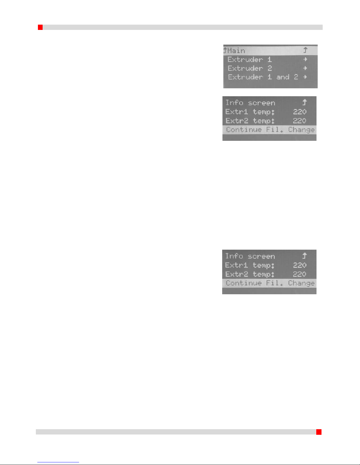
The meaning of the values is as follows:
1a. Extruder set temperature (Extruder 1);
1b. Actual extruder temperature (Extruder 1);
2a. Extruder set temperature (Extruder 2, dddrop leader twin only);
2b. Actual extruder temperature (Extruder 2, dddrop leader twin only);
3. Heated bed set temperature;
4. Actual heated bed temperature;
5. Feedrate, 100 % is de standard print speed;
6. Progress bar with time indication of elapsed time including percentage;
7. Extruder position on print bed;
8. Status communication field;
9. Actual extruder fan speed;
Page 10
9
EN 160518
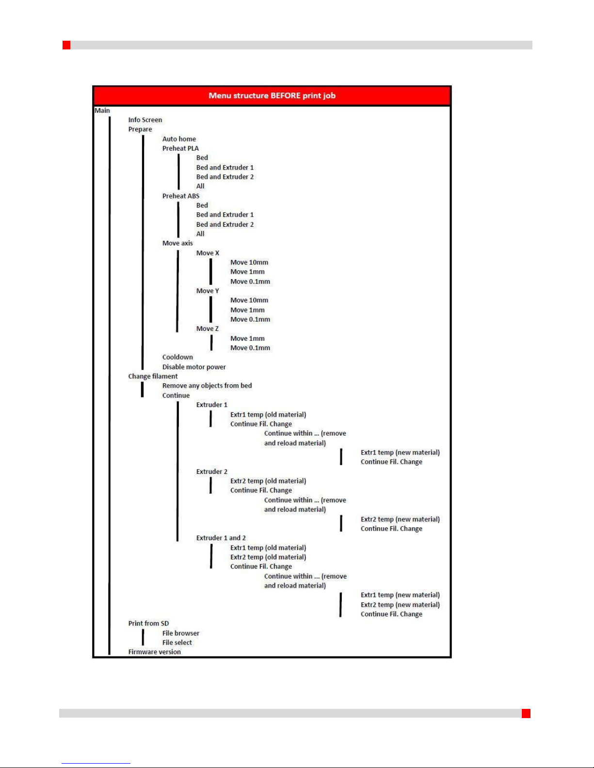
4.2 Menu structure BEFORE printing
Menu structure BEFORE a print job is started on a dddrop leader twin (in case of dddrop leader ignore all “Extruder 2” statements)
Page 11
10
EN 160518
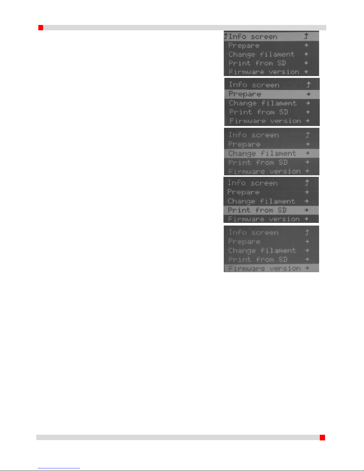
4.3 Main menu BEFORE print job
When the info screen is displayed, a press of the
button will show the main menu.
Info screen; the info screen has been explained in
4.1. Using the knob to select and click on this
function, the display returns to the info screen.
Prepare; this function contains settings that can
be made before a print job is started. The
detailed functions in prepare are explained in
4.3.1. During a print job, this menu item is
replaced by the Advanced menu (4.5.1).
Change filament; Using this function, filament can
be changed both before and during a print job. It
is however recommended to change the filament
before a print job is started. More information on
this is given in 4.3.2.
Print from SD; All g-codes (“machining codes”)
generated by Slic3r are shown in this file browser
function. More info is given in 4.3.3.
Firmware version; the firmware version on the
machine can be shown using this function. More
info is given in 4.3.4.
Page 12

11
EN 160518
4.3.1 Prepare menu
When the prepare function is chosen using the
selector knob, the following display is shown.
Main; the main menu is explained in 4.3, by
choosing this function one returns to the main
menu.
Auto home; using this function, the extruder(s)
move to a predetermined position (X0Y0Z0). For
safety reasons this is in the back left of the
machine. The moving bed moves up using this
command!
Preheat PLA/ABS; using this function, both the
extruder and the heated bed can be pre-heated as a
preparation before a print is started.
E.g.: Pre-heating for printing with PLA: Preheat PLA
=> Bed and extruder 1
Move axis; Auto home needs to be performed first.
Using this function, the position of X, Y, Z can be
altered manually. Besides this, material can be fed
through the extruder. First the operator has to
choose which shaft has to move or which extruder
has to move filament. Next the step size is selected:
10mm, 1mm or 0.1mm (Note: Step size 10mm is
only possible for movements of the X and Y
directions). Using the control knob a preferred
distance can be selected. A push of the button will
return to the previous menu.
Cooldown; using this function both the extruders
and the heated bed can be cooled down. When a
print is stopped during a print job, the cooldown
function is not enabled and the controls will
maintain the last known set temperatures. When a
print is completed, the cooldown function is
automatically enabled.
Disable Motor Power; this function disables the
hold function of the stepper motors.
Page 13

12
EN 160518
4.3.2 Change filament (BEFORE a print job)
Main; the main menu is explained in 4.3, by choosing
this function one returns to the main menu.
Continue; the user is warned to make sure all objects
are removed from the heated bed before continuing
with the procedure in order to prevent damage to the
extruder heads. Only click Continue if sure it is safe to do
so.
Extruder selection; next in the sequence is the selection
of the extruder of which the filament needs to be
changed by selecting Extruder 1, Extruder 2 or Extruder 1
and .
Current material temperature; before the current
material can be removed, the selected extruder has to
be heated to the material print temperature. Starting
value is 150C and needs to be increased using the jog
dial. When left at 150C the filament change process will
be terminated. After setting the current material print
temperature select Continue Fil. Change.
Sequentially the extruder will warm up to the selected
temperature. (Heating…). When this temperature is
reached (Heating done) the extruder will move towards
the filament change position.
When the status changes to Continue within...
(countdown timer), the old material can be removed and
the new material can be loaded. The material needs to
be loaded all the way into the nozzle. Confirm the
change by a click of the control knob.
New material temperature; Next the operator is
promted to set the new material print temperature.
Starting value is 150C and needs to be increased using
the jog dial. When left at 150C the filament change
process will be terminated. After setting the current
material print temperature select Continue Fil. Change.
The extruder continues to move to the position above
the container and extrudes an initial quantity of new
material in the container wiping the nozzle clean,
denoted by Extruding…in the status bar.
The filament change is complete and the status changes
to DDDROP Ready.
Page 14

13
EN 160518
4.3.3 Print from SD
Main; the main menu is explained in 4.3, by
choosing this function one returns to the main
menu.
All g-code files on the SD can be found using the
browsing function ‘Print from SD´. By using the
control knob rotary function a file can be
selected and the push function is given to start
the print job (Note that you have the same
materials supplied to the printer as the ones you
have used generating the g-code!)
The latest generated g-code automatically shows
on top.
4.3.4 Firmware version
Main; the main menu is explained in 4.3, by
choosing this function one returns to the main
menu.
This function shows the installed firmware
version.
Page 15
14
EN 160518
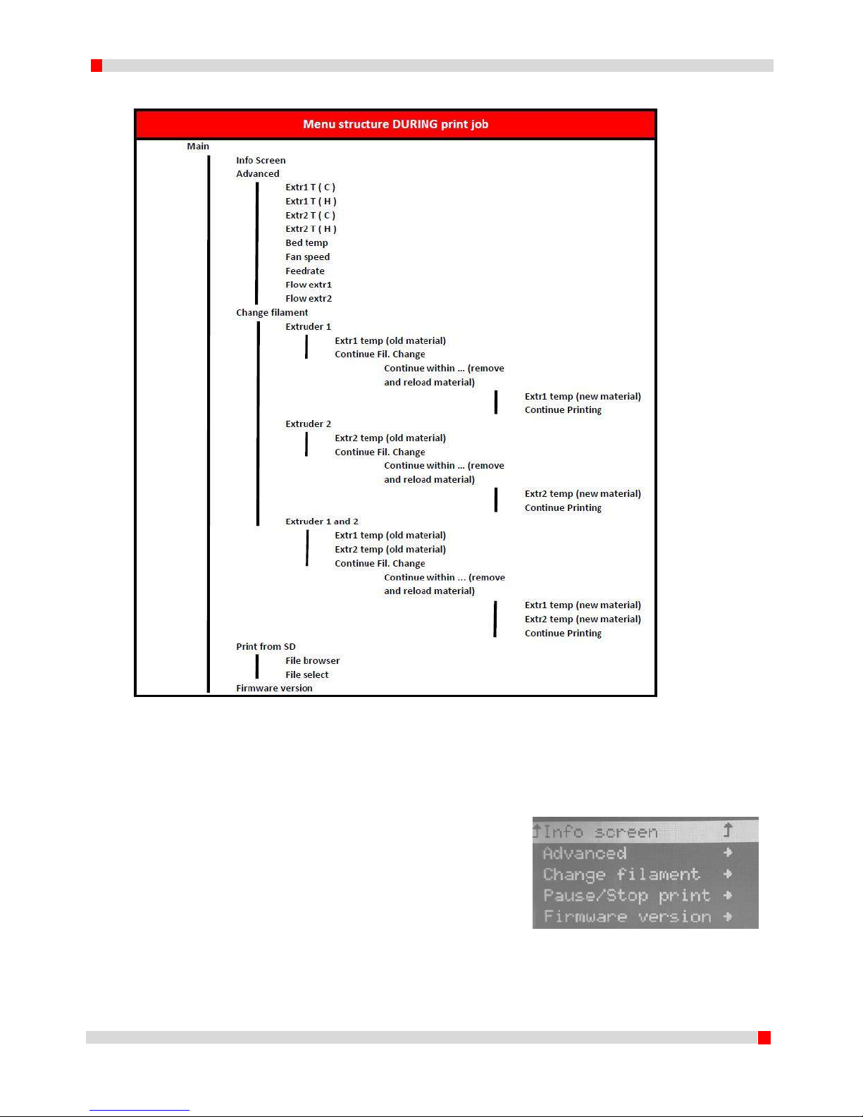
4.4 Menu structure DURING a print job
Menu structuurboom tijdens het printen voor dddrop leader twin (bij ddrop leader vervalt Extruder 2 temp en Flow 2)
4.5 Main menu DURING a print job
Info screen; the main menu is explained in 4.3, by
choosing this function one returns to the main
menu.
Advanced; with this function the print settings can
be altered on the go. More info is given in 4.5.1.
Change filament; Using this function, filament can
be changed both during a print job. It is however
recommended to change the filament before a
print job is started. More information on this is
given in 4.5.2.
Pause/Stop print; A print job can be paused
(unpaused) or stopped with this function .
Page 16

15
EN 160518
Firmware version; the firmware version on the
machine can be shown using this function. More
info is given in 4.3.4.
4.5.1 Advanced menu
Extr 1/2 T(C) or T(H); this function adjusts the extruder 1
or 2 nozzle temperature (degrees Celsius). T(H) is the
print temperature and T(C) the cooldown temperature
during nozzle inactivity.
Bed temp; this function adjusts the heated bed
temperature (degrees Celsius).
Fan speed; this function adjusts the fan speed (product
cooling). (%)
Feedrate; this function adjusts the total print speed
(feedrate). (%)
Flow 1/2; this function adjusts the extruder 1, 2 or both
material flow settings. (%)
Page 17
16
EN 160518
4.5.2 Change filament (DURING a print job)
Main; the main menu is explained in 4.3, by choosing
this function one returns to the main menu.
Extruder selection; next in the sequence is the selection
of the extruder of which the filament needs to be
changed by selecting Extruder 1, Extruder 2 or Extruder 1
and .
Current material temperature; before the current
material can be removed, the selected extruder has to
be heated to the material print temperature. Starting
value is 150C and needs to be increased using the jog
dial. When left at 150C the filament change process will
be terminated. After setting the current material print
temperature select Continue Fil. Change.
Sequentially the extruder will warm up to the selected
temperature. (Heating…). When this temperature is
reached (Heating done) the extruder will move towards
the filament change position.
When the status changes to Continue within...
(countdown timer), the old material can be removed and
the new material can be loaded. The material needs to
be loaded all the way into the nozzle. Confirm the
change by a click of the control knob.
New material temperature; Next the operator is
promted to set the new material print temperature.
Starting value is 150C and needs to be increased using
the jog dial. When left at 150C the filament change
process will be terminated. After setting the current
material print temperature select Continue Fil. Change.
The extruder continues to move to the position above
the container and extrudes an initial quantity of new
material in the container wiping the nozzle clean,
denoted by Extruding…in the status bar.
The filament change is complete and the status changes
to Printing….
Page 18

17
EN 160518
5 Slic3r
In order to print a 3D model, the dddrop printer requires model information in order to create a
printed model from 3D file. Slic3r is a program that converts a 3D model into this information, in a
format that the dddrop printer can read. Slic3r cuts the model in horizontal layers and generates
coordinates. These coordinates and settings together form the G-code. The installation and a quick
walk-through of Slic3r are given in this chapter. For more information, please visit the slicer website:
http://slic3r.org/.
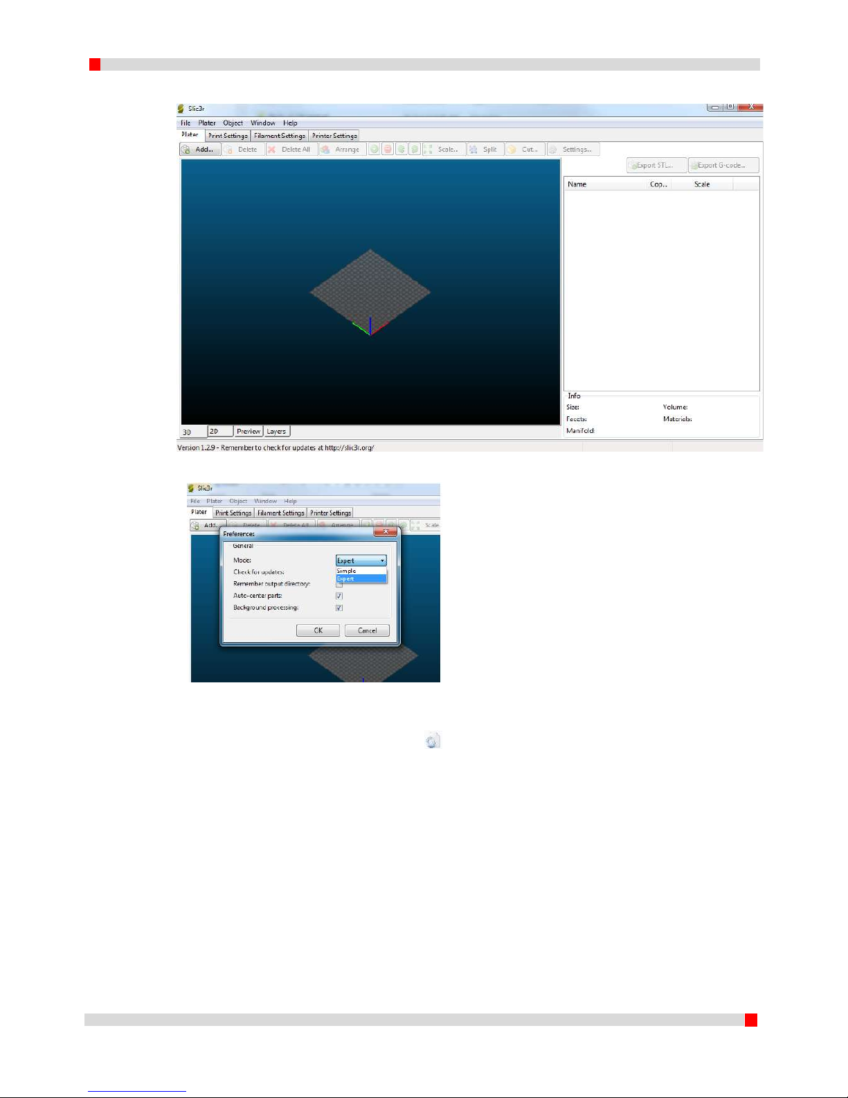
5.1 Slic3r Install
Slic3r is ready to use in 5 minutes.
1. Move the folder “Slic3r” (on the SD-card in the printer) on the desktop;
2. Open the folder and click on Slic3r.exe ( );
3. For first use, a screen pops up ‘Configuration Wizard’. ‘Cancel’ this screen, the configuration
is already ready for implementation in an .ini file that is made available by dddrop.
Figure 4. Slic3r configuration wizard
4. The screen ad shown in figure 5 appears. It is important to switch slic3r to Expert mode.
Select ‘File’ -> ‘Preferences’. The preferences screen appears (figure 6). Select ‘Expert mode’
Page 19
18
EN 160518
and click ‘OK’; restart Slic3r when prompted.
Figure 5. Slic3r tab ‘Plater’
Figure 6 Preferences 'Expert mode'
5. Go to ‘File’ -> ‘Load Config Bundle...’ and open the .ini file that is available in the copied
folder. The file is named ‘dddrop_X_X.ini’ ( ) (X denoting version); the user is prompted
that XX presets are successfully imported. Click ‘OK’.
6. Slic3r is installed and has the presets for the dddrop printer on board.
Page 20
19
EN 160518
5.2 Exploring Slic3r
Slic3r is supplied with an .ini file for the dddrop printer. The config file contains presets which makes
creating your own settings practically unnecessary. For more information please check
http://slic3r.org/.
5.2.1 Plater
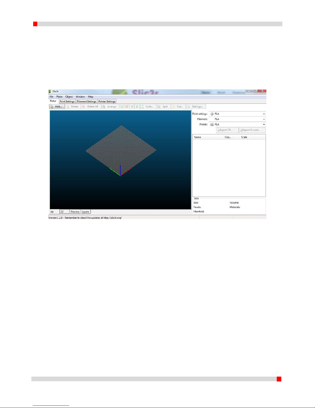
The first tab in Slic3r is named ‘Plater’. Here models are loaded, arranged and G-codes can be
generated using presets.
Figure 7. Tab 'Plater'
The model can be loaded using the ‘Add’ button or just be simply dragged onto the grid. Standard
view is 3D, but one can also choose for 2D (Top view), Preview (showing printing pattern) and layers
view (showing every layer in 2D detail).
Page 21

20
EN 160518
Figure 8. STL file loaded
The model will always be positioned in the middle of the grid. On the right-hand side a list of loaded
models is given. The buttons on top give the possibility to change the layout as follows:
‘Add’ – Ad a model to the grid;
‘Delete/Delete All’ – Remove a highlighted model or all models from the grid;
‘Arrange’- Slic3r determines an optimal model arrangement;
‘More/Less’ – Change the number of copies of a selected model;
‘45°/Rotate’ - Rotate about Z;
‘Scale’ – Scale the model up or down;
‘Split’ – Divide the model in multiple parts which can later be assembled;
‘Cut’ – Cut the model in Z (useful with high products);
‘Settings’ – Model specific settings;
Besides this there are 3 preset choices from the dropdown menus for Print settings, Filament
settings and Printer Settings. These are available after loading the supplied Config Bundle (.ini file).
‘Export G-code’ – Make a G-code from the current items on the grid;
‘Export STL’ - Make a STL of the grid. (Useful for future reference).
Page 22
21
EN 160518
5.2.2 Print Settings
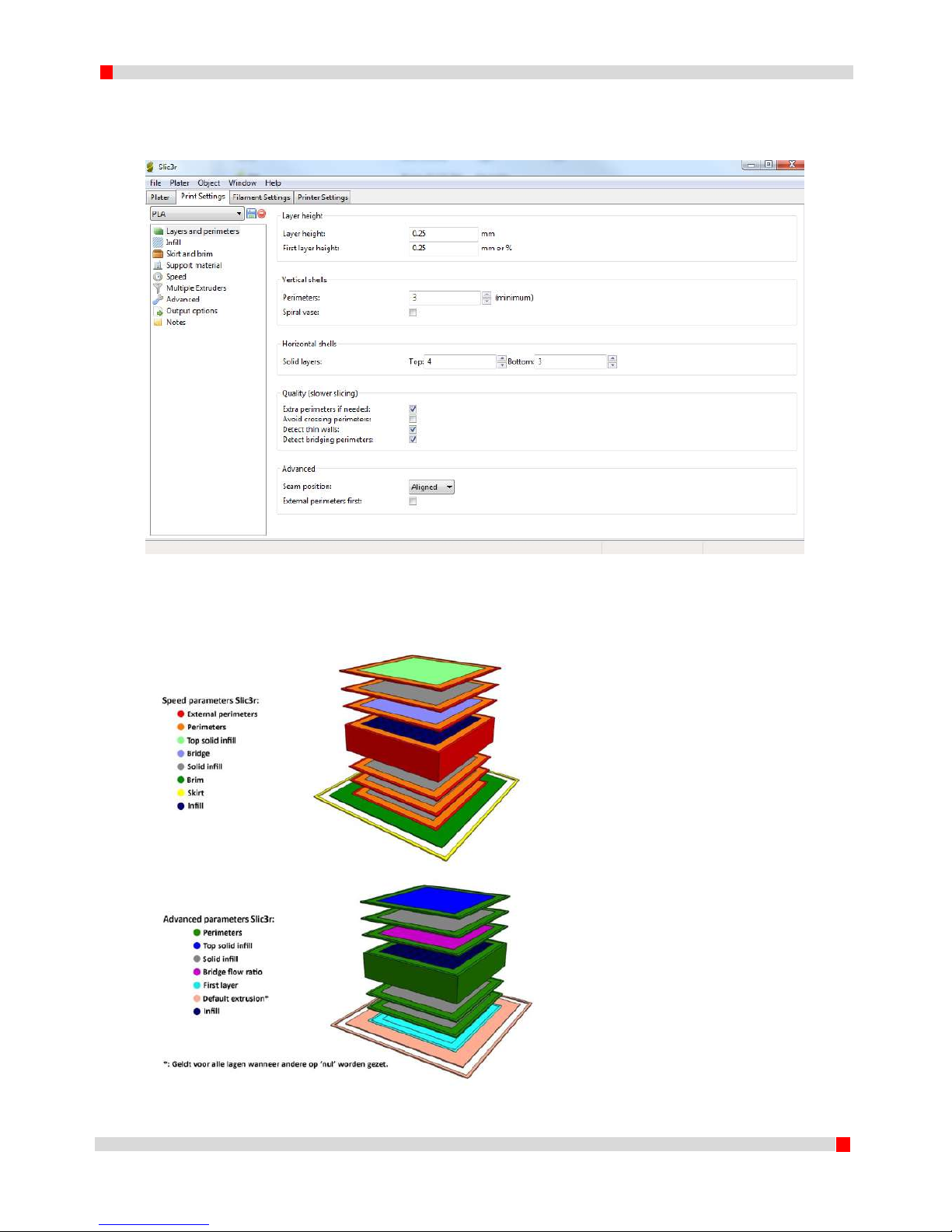
The ‘Print Settings’ tab makes it possible to change values of the part to be printed. All sub menus
are given on the left-hand side.
Figure 9. Tab 'Print Settings'
Most parameters are self-explanatory when the mouse printer is placed over the parameter. A
graphical representation of parameters is given in figure 10.
Figure 10. Indication Slic3r parameters.
Page 23
22
EN 160518
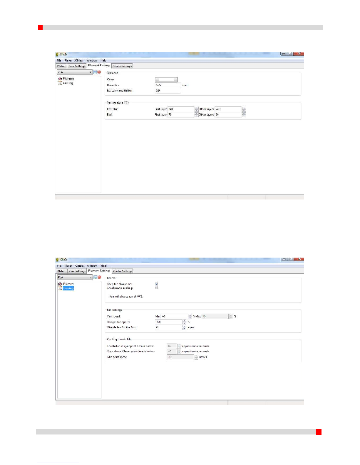
5.2.3 Filament Settings
The filament settings tab contains the material parameters.
Figure 11. Tab 'Filament Settings', submenu ‘Filament’
Slicer calculates the required extruder volume flow by the layer thickness, nozzle diameter and
filament diameter. It is important to do this accurately. An option is added to optimize the calculated
flow using ‘Extrusion multiplier’. First layer temperatures can also be customized.
The other sub menu covers the material cooling parameters.
Figure 12. Tab 'Filament Settings', submenu ‘Cooling’
Page 24
23
EN 160518
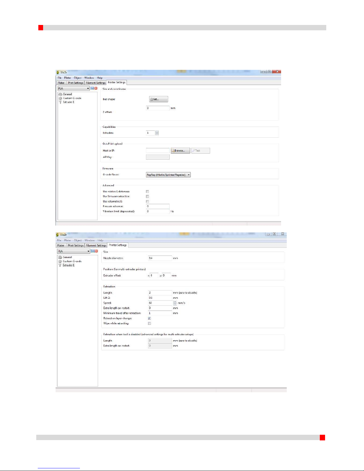
5.2.4 Printer Settings
The tab ‘Printer Settings’ contains printer specific data as bed shape, G-code language and start- and
encodes that have to be added to the G-code containing tasks to be performed before and after
printing the model. In the ‘extruder’ submenu, extruder specific values can be set.
Figuur 13. Tab 'Printer Settings'
Figure 14. Tab 'Printer Settings', submenu 'Extruder'
Page 25
24
EN 160518
5.3 Generating a G-code
It is strongly advised not to alter any of the standard values supplied with your printer in order to be
able to revert to the standard settings at any time.
Next the steps are given which are required to generate a G-code and save this code to the SD card.
1. Start Slic3r with pre-loaded config bundle. (click Slic3r.exe ( ));
2. Click Add, browse for the model to print in STL (of any other supported format) and click
Open. The file is automatically loaded in the center of the grid. When repositioning is
needed, use the buttons Arrange/rotate etc. or position by dragging.
Using right-click on the model, rotation around X and Y is also possible. This may be helpful
when the reference-axis of the design system is different than the system in the printer (Z
vertical);
3. Choose the preferred preset settings for Print settings, Filament settings and Printer
Settings. Use the dropdown menus in the top-right area of the ‘Plater’ tab. Use the table
below in order to make sure the right choice is made, for example:
For a single extruder print in PLA you choose PLA, PLA and PLA.
For a dual extruder print in PLA with PVA support material you choose PLA_Support_Twin,
PLA_Support_Twin, PVA_Twin PLA_PVA_Twin
4. Click Export G-code… select the SD-card and click Save.
5. Wait for the G-code to be exported (status bar bottom left) and take the SD-card from the
SD reader.
Extruder
1 2 Print settings
Filament settings (Leader)
Filament settings (Leader Twin)
Printer settings
Leader
ABS
[-]
ABS
ABS
[-]
ABS
PLA
[-]
PLA
PLA
[-]
PLA
Leader Twin
ABS
ABS
ABS_Twin
ABS_Twin
ABS_Twin
ABS_ABS_Twin
ABS
HIPS
ABS_Support_Twin
ABS_Support_Twin
HIPS_Twin
ABS_HIPS_Twin
PLA
PLA
PLA_Twin
PLA_Twin
PLA_Twin
PLA_PLA_Twin
PLA
PVA
PLA_Support_Twin
PLA_Support_Twin
PVA_Twin
PLA_PVA_Twin
Page 26

25
EN 160518
6 First print
This chapter covers the procedure required to start a print job.
WARNING
The machine is to be used in well ventilated areas only. Fumes that can occur during the printing
process are material dependent and, especially in case of insufficient ventilation, have to be
extracted.
WARNING
The printer is to be used with a closed cover only. The dddrop printer contains hot surfaces and
the moving parts can lead to injuries. Never reach into the printer when in use.
Always use the control know on the front of the printer or the on-off switch on the back of the
printer to control the print job.
Allow to cool for at least 10 minutes before opening the cover and reaching into the printer.
When opening and closing the cover there is a chance of pinching. Operate the cover using both
hands. Make sure the cover hinge is in lock position when opened and that the cover is in
positioning hooks when closed.
6.1 Preparation of material
NOTE: For changing filament BEFORE a print, see 4.3.2. For changing filament DURING a print see
4.5.2. The general preparation is given below.
1. Place filament (1.75mm) on the back side of the printer on the filament reel brackets. Check
that the filament is correctly wound on the reel and not in a loop which may block the
material supply resulting in a failed print.
2. Feed the filament through the filament guide to the quick connector and metal curved tube.
3. Press the lever of the spring-loaded idler wheel free of the driven wheel (of the required
extruder in case of LEADER TWIN) and feed the filament through the cooler all the way into
the nozzle. The front fan assembly can be moved out of the way for better visibility.
Feed until the extruder tip is reached and release the spring-loaded lever, allowing the idle
wheel to drive the filament into the driven wheel. Place the curved tube trough the lever
into the bearing.
4. Check the material and material choice of the generated file.
WARNING
Failure to remove ALL material of a previous build from the heated bed or a badly adjusted heated
bed can cause a collision and damage machine components.
6.2 Preparing heated bed
1. Clean the heated bed from residue of other prints.
2. Empty the container (See 7.2) and clean the brush (See 7.3).
3. Clean the heated bed with dddrop heat bed cleaner and paper.
4. Check correct heated bed adjustment.
5. Turn the printer ON by switching the switch on the back of the printer to the ‘I’ position and
wait for the printer to be initialized.
6. Select the preheat function in the ‘prepare’ menu for the filament of choice in 6.1. Note the
material of choice and extruder(s) choice. Only the extruder(s) that is (are) to be used should
be preheated. It is preferred to at least preheat the heated bed since this takes most time.
Page 27

26
EN 160518
6.3 Preparation of G-code
1. Follow the steps as described in 5.3 Slic3r/Generating a G-code. Take the material of choice
into account as has been supplied to the machine in 6.1
2. Export the generated G-code to the SD card and place it in the SD slot in the printer.
Close the cover.
WARNING
The machine contains hot and moving parts. It is strongly advised to only print with cover closed.
The machine can be stopped AT ANY TIME in case of an emergency by switching the power OFF or
disconnecting the power cord.
6.4 Start Print
1. Check if the container is empty and the brush and heated bed have been cleaned.
2. Check if the cover is correctly closed.
3. Select in the main menu PRINT FROM SD, select the generated print code and push the
button to confirm. The print is automatically started.
6.5 Taking out the printed model
1. Before opening the cover: Check if the printer is ready. The status bar should display print
finished and the total print time is given. The extruder is in its XY home position and the set
temperatures are in cooldown mode.
2. Before opening the cover: Check if the printer is cooled down. The actual temperatures of
nozzles and heated bed are given in the info screen.
3. Open the cover with both hands and check that the hinge is in lock position.
4. Take out the printed model. When it seems to be very stuck, the heated bed is probably still
too hot to take out the product. Allow the bed to cool; the product will automatically
become free. Be careful when using spatula or other tools to remove the product. Use
protective clothing (e.g. Gloves, safety glasses etc.)!
5. Empty the container.
6. Turn OFF the printer by switching the power switch to the O position.
Page 28

27
EN 160518
7 Maintenance
The dddrop printer is calibrated in order to make a quick start possible. If it however requires
recalibration or maintenance, an overview is given of the steps involved.
Clean the printer externally with a damp cloth. The internals can be cleaned carefully with a vacuum
cleaner.
WARNING
Failure to incorrectly, inaccurately or incompletely follow the calibration procedure will reduce
print quality.
WARNING
Linear guides and the acme threaded rod are greased. Make sure not to contact the grease as it
may work irritating and will stain cloths.
WARNING
Only use the supplied power cable when connecting your printer to the mains. Use a wall socket
with earth pins. Make sure that during maintenance the power supply is switched OFF and the
power cable is disconnected.
Make sure that before connecting the power cable to the mains the power switch is switched to
the OFF position (O).
The machine contains hot and moving parts. It is strongly advised to only print with cover closed.
The machine can be stopped AT ANY TIME in case of an emergency by switching the power OFF or
disconnecting the power cord.
Page 29

28
EN 160518
7.1 Adjusting heated bed
Goal: the heated bed is to be parallel with the path of the extruder and the distance between the
heated bed and the extruder is equal to 0.1mm;
1. Turn the 4 adjustment knobs below the heated bed all the way in (clockwise). This will
lower the heated bed, avoiding collisions between nozzle and heated bed in the steps
that follow. (Figure 18, right side).
2. Make sure the printer is in ‘home’ position by selecting ‘prepare’ -> ‘auto home’.
3. Switch off the printer by switching the power switch to the O position and disconnect
the power cable from the mains.
Figure 16. Overview of adjustment knob positions
Figure 17. Overview of adjustment knob positions
Page 30

29
EN 160518
4. Position the printer head manually above adjustment knob 1 (POSITION1, BACK LEFT).
Slide a gage or piece of paper (+/- 0.1mm) between the glass and nozzle.
Turn the adjustment knob 1 (POSITION1, BACK LEFT) out (counterclockwise; figure 18
left, the heated bed moves up on position 1). Continue until the gage or piece of paper is
on the edge of pinching. Stop and remove the gage or piece of paper.
Figure 18. Adjustment knobs moving the bed up (left) and moving the bed down (right)
5. Position the printer head manually above adjustment knob 2 (POSITION2, BACK RIGHT).
Slide a gage or piece of paper (+/- 0.1mm) between the glass and nozzle.
Turn the adjustment knob 2 (POSITION2, BACK RIGHT) out (counterclockwise; figure 18
left, the heated bed moves up on position 2). Continue until the gage or piece of paper is
on the edge of pinching. Stop and remove the gage of piece of paper.
6. Position the printer head manually above adjustment knob 3 (POSITION3, FRONT
RIGHT). Slide a gage or piece of paper (+/- 0.1mm) between the glass and nozzle.
Turn the adjustment knob 3 (POSITION3, FRONT RIGHT) out (counterclockwise; figure 18
left, the heated bed moves up on position 3). Continue until the gage or piece of paper is
on the edge of pinching. Stop and remove the gage of piece of paper.
7. Position the printer head manually above adjustment knob 1 (POSITION4, FRONT LEFT).
Slide a gage or piece of paper (+/- 0.1mm) between the glass and nozzle.
Turn the adjustment knob 1 (POSITION4, FRONT LEFT) out (counterclockwise; figure 18
left, the heated bed moves up on position 4). Continue until the gage or piece of paper is
on the edge of pinching. Stop and remove the gage of piece of paper.
8. Continue with steps 4-7 of this procedure until the heated bed is parallel with the path
of the extruder.
Page 31

30
EN 160518
7.2 Empty the container
The dddrop LEADER and LEADER TWIN are equipped with a container on the front of the build
volume. This container catches material that needs to be extruded in order to initiate extruder flow.
With the LEADER TWIN this has to be done also at ‘tool change’ operations (switch between
extruders). The container is magnetically mounted to the brush bracket. The container also has two
cut-outs to create room for the fastener items of the brush, also functioning as a vertical block for
the container.
1. Check that the printer is not busy but stationary (no print job running). Check that the
printer is cooled down.
2. Open the cover and check that the hinge is in locking position.
3. Take the container in one hand and the bracket in the other. A light pull towards the
operator separates the container from the bracket.
4. Empty the container.
5. Place the empty container back on the bracket. Ensure contact of the magnets with the
metal and position the cut-outs over the fasteners.
6. Close the cover.
7.3 Cleaning the brush
The dddrop LEADER and LEADER TWIN are equipped with a brush on the front of the build volume.
This brush cleans the nozzle from material that needs to be extruded in order to initiate extruder
flow. With the LEADER TWIN this has to be done also at ‘tool change’ operations (switch between
extruders). A clean brush is of interest in order to get the best print results.
1. Check that the printer is not busy but stationary (no print job running). Check that the
printer is cooled down.
2. Open the cover and check that the hinge is in locking position.
3. Remove any material residue from the brush.
4. Close the cover.
7.4 Adjusting bed to nozzle distance (major adjustments only!)
This setting is normally achieved by adjusting the heated bed adjustment knobs. If this however does
not create sufficient room (too much or too little tension in the heated bed springs) the possibility
exists to adjust the optical sensor several millimeters in Z direction. This is not necessary in normal
use!
1. Put the extruder in ‘home’ position by selecting ‘prepare’ -˃ ‘auto home’;
2. Switch the printer off by switching the power switch to the O position and disconnect
the power cable from the mains.
3. Turn the 4 adjustment knobs below the heated bed all the way in (clockwise). This will
lower the heated bed, avoiding collisions between nozzle and heated bed in the steps
that follow. (Figure 18, right side).
4. Determine whether more tension (heated bed lower, closer to the frame) or less
tension is needed (heated bed higher, further from the frame). Loosen the two bolts on
the back of the frame holding the Z sensor in place. Move the sensor up or down (as
required) in the slot. Tighten the bolts
5. Continue with 7.1, adjusting the heated bed until the surface is parallel with the path of
the extruder.
Page 32

31
EN 160518
8 Safety and Conformity
8.1 Electromagnetic compatibility (EMC)
This product may cause radio interference which may require the user to take necessary
precautions. The dddrop leader may in some cases loose functionality due to ESD. This functionality
can be restored by switching the machine off and back on.
WARNING
Always switch off and unplug the machine during maintenance or adjustments.
8.2 Electrical safety
The dddrop leader operates on voltages less than 24 volt (Extra-low-voltage) internally. The power
supply used however falls in the Low Voltage directive and is CE marked.
For further information on electrical safety please refer to the data sheets of the used power supply.
WARNING
Always switch off and unplug the machine during maintenance or adjustments
8.3 Mechanical safety
The dddrop leader contains moving parts. Engine torque is however limited in order to minimize the
chance of serious injury. It is highly recommended to only reach into the printer when it is switched
off and when it is cooled down.
WARNING
Always allow the printer to cool for at least 30 minutes before any maintenance or adjustments.
8.4 Risk of burn
With nozzle temperatures up to 300 °C and heated bed temperatures up to 150 °C, the risk of burn
exists. The hot parts are covered as much as possible and have been marked with WARNING
symbols. It is highly recommended to only reach into the printer when it is switched off and when it
is cooled down.
WARNING
Only use the printer in a well ventilated area.
8.5 Health
The dddrop leader is designed to print with PLA and ABS filaments. The use of other materials is not
recommended though technically possible. During print jobs fumes may find their way into the area
where the printer is set up. When printing ABS for example, small concentrations of styrene vapor
may cause headaches, fatigue, dizziness, depression, concentration problems and a feeling of
intoxication.
Proper ventilation is necessary and a long term exposure should be omitted. It is recommended to
use a fume extractor. It is obligated to make use of fume extraction in offices, classrooms etcetera.
Printing of pure PLA is considered to be safe, however ventilation is advised as fumes may also arise
from (color-) additives.
8.6 General note on safety
The dddrop leader is not a toy. It is not intended to be used by persons (including children) with
reduced physical or mental capabilities, users who lack the knowledge and experience, unless under
Page 33
32
EN 160518
the supervision by or have had instructions to use the machine, from a person who is responsible for
their safety. Children should be only let in the room with the printer when under constant
supervision.
The aforementioned information is believed to be correct, but is not exhaustive and should
therefore only be used as a tool for safe use. The conditions used for assembling, transportation,
storage, use and disposal of the products are beyond our control and possibly beyond our
knowledge. For these and other reasons, we assume no responsibility and expressly disclaim liability
for loss, injury damage or expense that may result in any way from maintenance, handling, storage,
use or disposal of the product.
The information in this document was obtained from sources that are reliable in our opinion. The
information is however provided without any warranty to be complete or correct.
Page 34
33
EN 160518
 Loading...