

DCT Syrus Installation And Configuration Manual
D i g i t a l C o m m u n i c a t i o n T e c h n o l o g i e s
Syrus
Installation and Configuration Manual
V1 - December 2013
08
Fall
www.digitalcomtech.com

Contents
INTRODUCTION ............................................................................................................................................... 4
COMPATIBILITY .............................................................................................................................................. 4
SPECIFICATIONS ............................................................................................................................................. 5
LEDS ................................................................................................................................................................... 7
SYS .................................................................................................................................................................................................. 7
GPS ................................................................................................................................................................................................. 7
NET ................................................................................................................................................................................................. 7
INPUTS AND OUTPUTS .................................................................................................................................. 8
CARE AND CAUTION ....................................................................................................................................... 9
OPERATING TEMPERATURE ...........................................................................................................................................................9
HOW TO REMOVE SIM CARD..........................................................................................................................................................9
HOW TO REMOVE THE INTERNAL BATTERY ...............................................................................................................................9
SET UP THE CORRECT PIN FOR THE SIM CARD. ........................................................................................................................9
DO NOT LEAVE THESE WIRES UNPROTECTED .........................................................................................................................9
INSTALLATION .............................................................................................................................................. 10
GETTING STARTED ....................................................................................................................................... 12
Support Site Getting Started Section ........................................................................................................................... 12
Setting the unit's ID ............................................................................................................................................................. 12
Setting the APN and PIN.................................................................................................................................................... 12
Creating a Destination Point (DP) ................................................................................................................................ 13
Creating a Destination Address (DA) .......................................................................................................................... 14
Creating a time-period criterion ................................................................................................................................... 14
Tying a signal to an event ................................................................................................................................................. 15
EVENT MACHINE ........................................................................................................................................... 19
TRIGGERS.......................................................................................................................................................................................... 19
ACTIONS ............................................................................................................................................................................................ 20
EVENTS ............................................................................................................................................................................................. 20
SIGNALS............................................................................................................................................................................................. 21
Examples ................................................................................................................................................................................... 21
DETAILED COMMAND EXPLANATION ..................................................................................................... 22
UNIT'S ID ......................................................................................................................................................... 22
IMEI AS ID ....................................................................................................................................................... 22
ENABLING THE UNIT ON GSM AND GPRS ............................................................................................... 23
DESTINATIONS (DPS AND DAS) ................................................................................................................ 25
SYRUS COMMANDS ....................................................................................................................................... 27
DA - DESTINATION ADDRESS ..................................................................................................................................................... 27
Qualifiers: Q, S, R. .................................................................................................................................................................. 27
Examples:.................................................................................................................................................................................. 27
ED - EVENT DEFINITION .............................................................................................................................................................. 28
Qualifiers: Q, S, R. .................................................................................................................................................................. 28
EV - EVENT MESSAGE ................................................................................................................................................................... 29
rev1 – Dec 2013 www.digitalcomtech.com 2

Qualifiers: R. ............................................................................................................................................................................ 29
Example: ................................................................................................................................................................................... 29
Extended EV Tags formats: .............................................................................................................................................. 30
Example: ................................................................................................................................................................................... 30
GC - COUNTERS, TIMERS, DISTANCERS .................................................................................................................................... 31
Qualifiers: Q, S, R. .................................................................................................................................................................. 31
Examples:.................................................................................................................................................................................. 32
GS - SPEED LIMIT ........................................................................................................................................................................... 33
Qualifiers: Q, S, R. .................................................................................................................................................................. 33
Examples:.................................................................................................................................................................................. 33
ID - IDENTIFICATION ..................................................................................................................................................................... 34
PV - POSITION-VELOCITY ............................................................................................................................................................. 35
Qualifiers: Q, R. ....................................................................................................................................................................... 35
RF - RADIO FREQUENCY MODULE CONFIGURATION ............................................................................................................ 36
Qualifiers: Q, S, R. .................................................................................................................................................................. 36
Examples:.................................................................................................................................................................................. 36
RT - RESET MESSAGE .................................................................................................................................................................... 37
Qualifiers: S, R......................................................................................................................................................................... 37
SI - SIM CARD ID ........................................................................................................................................................................... 38
Qualifiers: Q, R. ....................................................................................................................................................................... 38
Examples:.................................................................................................................................................................................. 38
SS - SIGNAL STATUS ...................................................................................................................................................................... 39
Qualifiers: Q, S, R. .................................................................................................................................................................. 39
Examples:.................................................................................................................................................................................. 39
ST - STATUS ..................................................................................................................................................................................... 40
Qualifiers: Q, R. ....................................................................................................................................................................... 40
TD - TIME AND DISTANCE ........................................................................................................................................................... 41
Qualifiers: Q, S, R. .................................................................................................................................................................. 41
Examples:.................................................................................................................................................................................. 41
VR - VERSION NUMBER ................................................................................................................................................................ 42
Qualifiers: Q, R. ....................................................................................................................................................................... 42
XADP - DESTINATION POINTS ................................................................................................................................................... 43
Qualifiers: Q, S, R. .................................................................................................................................................................. 43
Examples:.................................................................................................................................................................................. 44
XAEF - EXTENDED-EV MESSAGE FORMATS ........................................................................................................................... 45
Qualifiers: Q, S, R. .................................................................................................................................................................. 45
Example: ................................................................................................................................................................................... 45
XAID - IMEI AS ID ........................................................................................................................................................................ 46
Qualifiers: Q, S, R. .................................................................................................................................................................. 46
XAIM - IMEI CONSULT ................................................................................................................................................................ 46
Qualifiers: Q, R. ....................................................................................................................................................................... 46
XANS - NETWORK STATUS ......................................................................................................................................................... 47
Qualifiers: Q, R. ....................................................................................................................................................................... 47
ERROR LIST .................................................................................................................................................... 50
SIGNAL LIST .................................................................................................................................................... 51
SCRIPT EXAMPLE .......................................................................................................................................... 52
rev1 – Dec 2013 www.digitalcomtech.com 3

Introduction
This manual is intended for Syrus firmware 2 only
The following is an introduction manual for the DCT Syrus GPS tracking device, its main
purpose is to provide a quick reference for the installation and configuration of the device.
Compatibility
The Syrus firmware 2 is only compatible with the most recent Syrus hardware. Likewise,
the most recent hardware is not backwards compatible with the firmware 1 family.
The benefits of the most recent hardware and the new firmware 2, are the many
accessories and functionalities only available to the firmware 2, such as:
ECU Monitor accessory.
I/Os Expander accessory.
Time Windows.
Sim Card ID.
GPS Back and Forward Logs.
Register status.
UDP Network.
Virtual Hour Meter.
Commands associated to the ECU Monitor.
New signals:
o GPS antenna connection status.
o Output short-circuits.
o Idle signal.
o And others...
rev1 – Dec 2013 www.digitalcomtech.com 4

Specifications
Power
DC Voltage: 8V - 32 V
Current consumption:
o With Internal battery at null charge (IDLE)
o Long term average: 50 mA @ 12V.
o Long term average while on power saving mode: 6mA @ 12V.
Reverse voltage polarity protection.
High transient voltage (as seen on automotive applications) protection.
Thermal shutdown and current limit protection.
Inputs/Ignition
3 Auxiliary Inputs + 1 Ignition Input. Max 30V.
Impedance: 50 K-ohms (Pull-Up)
1 Analog to Digital Input. 0V - 10V. This input has a protection against voltages greater
than 10V.
Outputs
2 Open Drain Outputs.
Continuous current capacity: 1.8A
Maximum instantaneous current (< 1 sec): 10A
Maximum switching voltage: 30V
Over temperature shutdown at 165 C.
Over current shutdown. The output restarts automatically after the over current state
finishes, this can take up to 5 seconds. The G07 signal transitions to True when the over
current state is detected.
ESD protection.
Environment
Charging temperature: 0 C to +45 C
Operating temperature: -20 C to +70 C
Storage temperature: -30 C to +85 C
Humidity: up to 95% non-condensing
rev1 – Dec 2013 www.digitalcomtech.com 5
GPS Solution
MTK MT3329
Frequency
L1, 1575.42MHz
Sensitivity
Acquisition -148dBm, cold start
Reacquisition -160dBm
Tracking -165dBm
Channels
66
TTFF
Hot start: 1 second typical
Warm start: 33 seconds typical
Cold start: 35 seconds typical
Altitude
Maximum 18,000m (60,000 feet)
Velocity
Maximum 515m/s (1000 knots)
Acceleration
Maximum 4G
Update Rate
1Hz (default), maximum 10Hz
DGPS
RTCM protocol / SBAS (default) [WAAS, EGNOS, MSAS, GAGAN]
AGPS
Support
Data transmission
GPRS Class 12 & Class 10 Max. 86 kbps (DL and UL) Coding schemes.
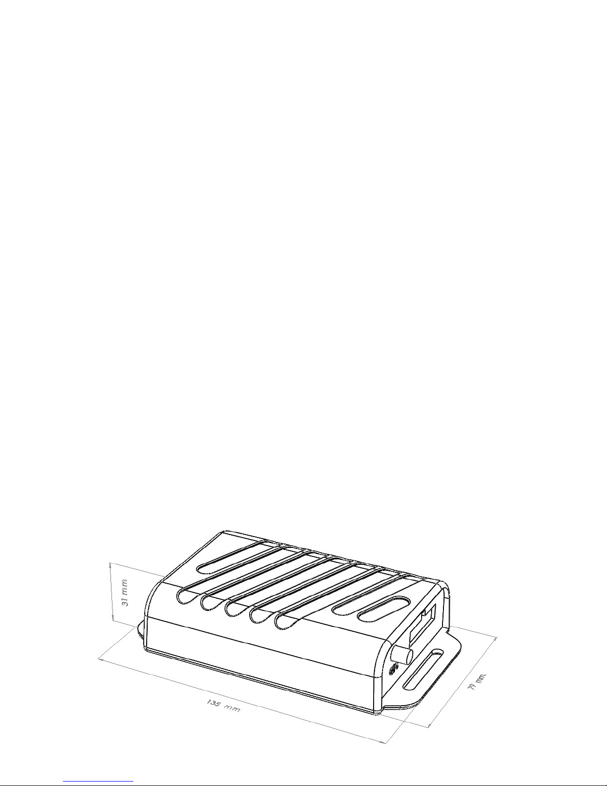
Dimensions
CS 1-4
LxWxH = 135 mm x 79 mm x 31 mm
GPS Module
GPRS Module
rev1 – Dec 2013 www.digitalcomtech.com 6

LEDs
SYS
RED LED is not a power indicator; it is a system fault or system abnormal status indicator. Under
normal operation this LED is OFF, it will also flash once when the unit has successfully restarted
and initialized the Syrus application. To verify if the unit is ON, check the state of the GPS and NET
LEDs, which will always show some kind of activity.
- 2 seconds ON – 1 second OFF – (SYS Error) – general system error, lack of SIM or other
hardware related issue.
- Flashes twice rapidly (Airplane Mode) – indicates RF Module is Off, and no communication
via Syrus commands is available.
- Short 0.5 sec flash every 5 seconds (Power Saving Mode) – indicates the unit is sleeping or in
Power Saving Mode.
- On/Off repeatedly every 0.5 seconds (Jamming Detected) – communication jamming was
detected (this could be from an external jammer)
GPS
When both the Red and Yellow LEDs flash in unison, it indicates a GPS Error.
External GPS Antenna in short circuit or internal hardware fault.
YELLOW LED is a GPS Signal indicator.
3 states that indicate GPS Signal Quality (We refer to the adquisicion of GPS Coordinates, latitude and
longitude, as the GPS Fix – fixing its position).
- No GPS Fix – the LED does not flash at all and is always off.
- Low GPS Quality – Show flash every 1 second – indicates low GPS quality
- High GPS Quality – Shows 2 rapid flashes every 1 second
NET
Network Error: indicates a GSM Registration Error. Possible causes:
- No SIM Card inserted, PIN error, or network rejects the SIM card registration
4 States:
On 0.5 seconds / Off 0.5 seconds – Not registered to either GSM or GPRS
On 0.5 seconds / Off 3 seconds – Registered to GSM network, but not GPRS network
Rapid flash twice – attached to the GPRS Network
Solid On – Voice call in progress
rev1 – Dec 2013 www.digitalcomtech.com 7
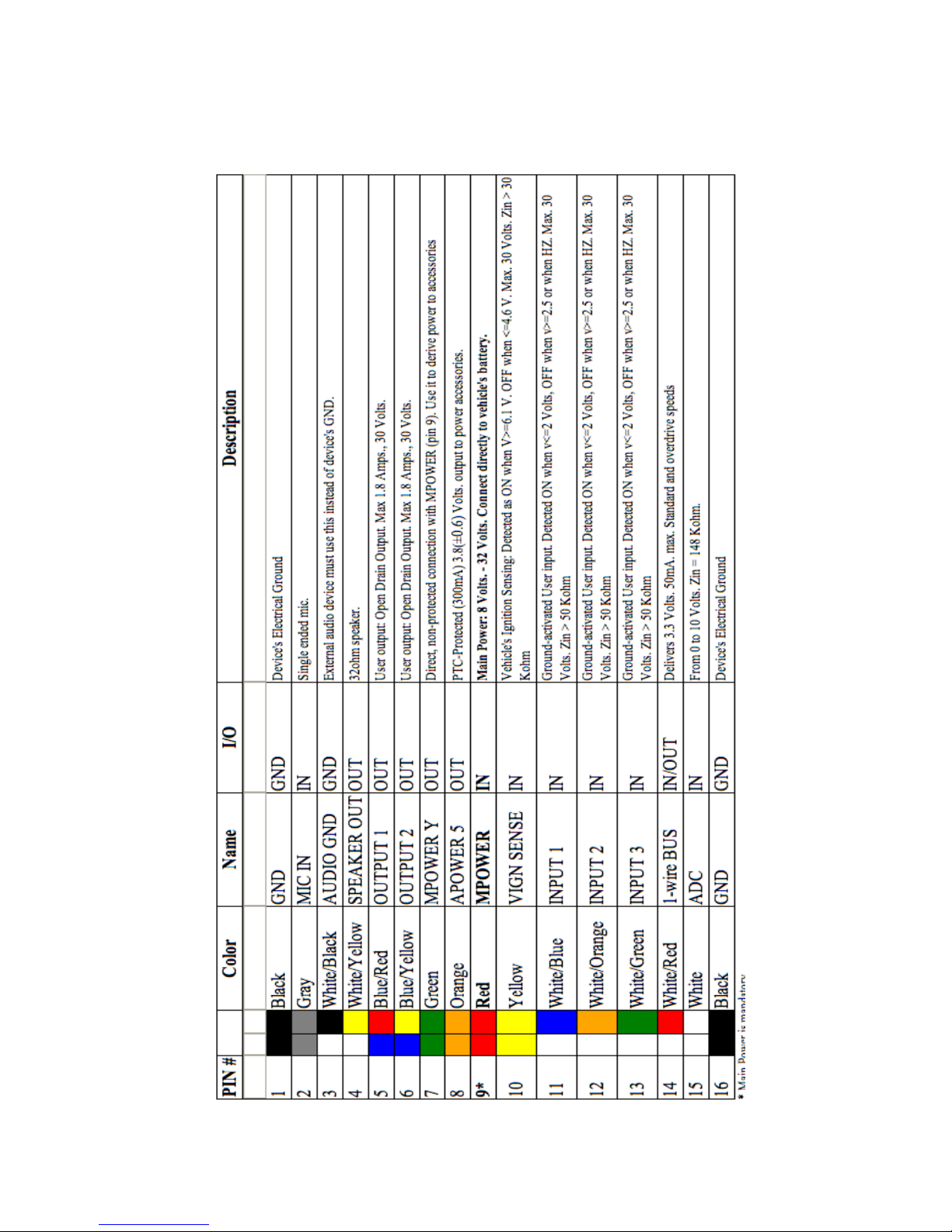
Inputs and Outputs
rev1 – Dec 2013 www.digitalcomtech.com 8

Care and Caution
Operating Temperature
Due to the limitations on the operation of the Lithium polymer battery, the temperature while charging the battery
must be 0ºC to 45ºC, and the regular operating temperature must be -20ºC to 70ºC. For more information about the
Lithium polymer batteries, visit:
http://en.wikipedia.org/wiki/Lithium-ion_polymer_battery orhttp://www.batteryuniversity.com/parttwo-34.htm
How to remove SIM Card
Always send an >SRT< command before removing the SIM card, due to the risk of possible damage to the SIM
card. Follow these steps in order to prevent these issues:
- Send a Reset (>SRT< command) via Serial port.
- Remove SIM card after sending the >SRT< command. That means you have around 10 seconds to
remove the SIM card.
How to remove the internal battery
Always send a >SRT< command before removing the battery if the external power supply is not connected, due to
the risk of possible data loss or data corruption in the device memory. Follow these steps in order to prevent these
issues:
- Send a Reset (>SRT< command) via Serial port.
- Remove the battery after sending the >SRT< command. That means you have around 10 seconds to
remove the battery.
If the external power supply is connected, the battery can be replaced without sending the >SRT< command.
Set up the correct PIN for the SIM card.
The SIM card may be blocked if the PIN parameter is configured using the >SRFI< command with a wrong SIM
card PIN.
Do Not Leave These Wires Unprotected
All the wire end tips must be kept insulated when not in use to prevent damage and undesired behavior on the unit.
This is especially important for the following wires:
o Pin 7 - Green
o Pin 8 - Orange
o Pin 14 - White/Red
For more details of each wire, please consult the Inputs/Outputs section.
rev1 – Dec 2013 www.digitalcomtech.com 9

Installation
The Syrus
environmental conditions are met:
o No exposure to water.
o No direct exposure to sun light.
o Away from excessive heat sources like the motor or the exhaust's path.
o Away from excessive cold sources like a truck's refrigerator or AC system.
o Not attached to a highly vibrating structure.
o The Syrus has an internal GSM antenna that will assure GPRS communication
o The Syrus has an internal GPS antenna, and a connector for an optional external
The unit's location/position can be such that it remains hidden. The LEDs indicators do
not have to be visible but it is recommended some access to them for
failure/diagnostics situations. The same recommendation holds for physical access to
the unit's serial port.
Power Supply
The unit's power cables should be directly connected to the vehicle's battery (12V or
24V). The unit supports an operating voltage range from 8V to 32V.
When the unit is not being used in a vehicle (e.g. lab testing) it must be powered by a
12V DC adapter that supplies a minimum current of 800mA.
Warning: The internal lithium polymer battery has an integrated automatic cut off
circuit to protect against over-charge, over-current and over-discharge. After long
disconnection periods, the battery may activate its over discharge protection circuit.
The unit is shipped with an unplugged battery connector to help prevent this state.
Plug this connector in before connecting the main power and wait for activity
indication on the green LED. It is not recommended to unplug the battery, except for
seldom-long storage periods. Refer to Care & Caution Section to see how to remove
the Battery or the SIM card.
Even though it is possible for the unit to work with no internal battery, it is
recommended to always use the battery; this is to prevent any data loss or memory
corruption that can be caused due to momentary external power loss.
TM
can be installed in any location of any type of vehicle as long as some
under normal vehicular conditions. The unit must not be installed inside a metal
structure that could act as a Faraday cage, which could lower the signal strength.
GPS antenna. When using the internal antenna, the units must be located so that
it has minimal metal obstructions to the sky view and with the upper part facing
up. It is recommended to use the external GPS antenna in most cases.
rev1 – Dec 2013 www.digitalcomtech.com 10
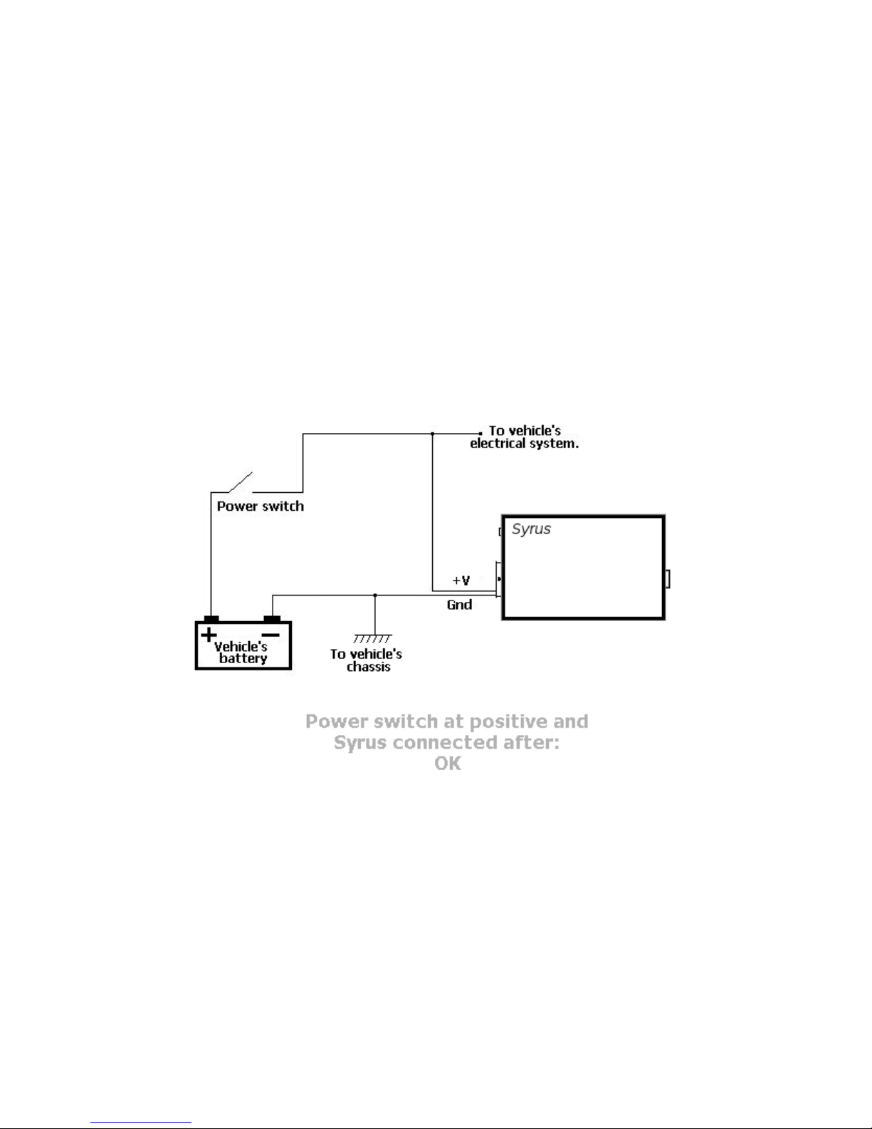
Vehicles with a main power switch
When the vehicle has a main power switch to cut/restore the battery voltage, some
recommendations have to be followed:
o If the switch disconnects the positive voltage of the vehicle's battery,
the Syrus can be connected before or after the switch. When connected before it
will keep on receiving the vehicle's power whenever the switch is off. If it is
connected after the switch, the unit will run with its optional back up battery
whenever the switch is turned off.
See the following figures for a better understanding of connecting the unit when the
vehicle uses a main power switch:
rev1 – Dec 2013 www.digitalcomtech.com 11

Getting Started
Support Site Getting Started Section
On the DCT support site (support.digitalcomtech.com) upon registering you have the
option to visit the getting started page. We recommend you go here first and refer to the
following for examples on how to further configure the device and get started
programming. Also we recommend using Syrus Desk software and test all these commands
so you can see first-hand how the device responds.
Setting the unit's ID
The default Syrus behavior is to use the unit's IMEI as ID. It is recommended to use this
setting as the IMEI is unique for each unit. However it is possible to use a user defined ID in
order for the unit to be identified on the AVL server. The default value for the unit's ID is
0000. This field may be any string of 10 characters maximum.
For this example let’s call our unit EXAMPLE:
>SIDEXAMPLE<
To enable the unit to use the user defined ID, use:
>SXAID0<
To disable the use of user defined ID and instead use the IMEI of the device as the ID, use:
>SXAID1<
Setting the APN and PIN
After configuring an ID, the next step is enabling the unit on the GSM/GPRS network. For
this an APN provided by the cellular carrier is required and depending on the SIM card
configuration a PIN value could also be required. For this example we will use
APN internet.carrier-name.com and PIN 1234.
Setting the SIM card's PIN:
>SRFI1234<
If your SIM card does not requires a PIN you can omit this step.
Setting the APN:
>SRFAinternet.carrier-name.com<
rev1 – Dec 2013 www.digitalcomtech.com 12

At this point the unit will try to register on GSM and on GPRS (you can see this status live
on SyrusDesk).
Although PIN and APN parameters take effect immediately the unit may take up some time
on registering to the network if previous erroneous information was used. You can wait for
the unit to register or you can speed up the process by resetting the communications
module with the>SXAGP1< command.
Using the XANS command it is possible to query the current GSM and GPRS registration
status. Please refer to the LEDs section and to the XANS command, for an more information
on the unit's current registration status.
Creating a Destination Point (DP)
Now that we have the unit working on the GSM/GPRS network the unit is ready to send and
receive communications from IP servers and phone numbers. For our example we need to
create a Destination Point (DP) which holds our remote server IP number or address and
the serving port that it is using for listening to TCP connections or UDP datagrams.
Refer to the section below for building your own TCP/UDP listener
For this example we will use a server located on the address avl.server.com , which
listens for TCP connections on the port 2145. Since it is a TCP server we must choose an
index from 00 to 03. In this example the index 00 will be used for no particular reason:
>SXADP0000avl.server.com;2145<
An IP address could also be specified. Supposing we wanted to use the IP number
192.168.0.1 we would have to send:
>SXADP0000192.168.0.1;2145<
Having set the DP, the unit will automatically start opening a TCP connection with the
server (as long as GPRS is ready) even if it has no messages to send to it. This is a
programmed feature of the unit that makes it reopen the TCP connection whenever the
network is available after being down or whenever the connection gets closed.
Use the XANS command to consult the state of the current DP:
>QXANS<
The unit might reply like this:
>RXANS1,internet.carriername.com,1234,,;1,1,null,1,22,1,1,18.18.9.8,1;socket://avl.serve
r.com:2145,0, -1,,1,,,,0,0,0,,,,0,,,,25\;0,0,0,0,,,17;28,3,101,0,0,,5,42,
socket://avl.server.com:2145;<
rev1 – Dec 2013 www.digitalcomtech.com 13

Indicating that the connection to the DP has not been established yet. If this state persists,
some considerations have to be taken:
The AVL software server is not running or it is running but it is not listening for TCP
connections.
The listening port and/or address is wrong.
The server is behind a firewall/router/NAT that prevents the TCP listener from receiving
the incoming connections.
The server is accepting the connection but it is closing it immediately, or a few seconds
later.
The Syrus is behind a cellular carrier's NAT which has the selected port blocked.
The selected APN has no Internet access. Or in case of a private network, the APN has no
access to the network where the AVL server is running.
There are network related problems that prevent the unit from communicating, even if it is
GPRS attached.
When the unit has connected to the server, the XANS reply could be something like:
>RXANS1,internet.carriername.com,1234,,;1,1,null,1,22,1,1,18.18.9.8,1;socket://avl.serve
r.com:2145,3, -1,,1,,,,0,0,0,,,,0,,,,25\;0,0,0,0,,,17;28,3,101,0,0,,5,42,
socket://avl.server.com:2145;<
Please refer to the XANS command for more information on the values returned by
this message.
Creating a Destination Address (DA)
As mentioned on the Destinations (DPs and DAs) section a Destination Address (DA) must be
created so that an event's routing option can be completed. In our example we only have to
create a DA with a single Destination Point which is the one we just created. We have no
restrictions for the DA range (0-9) so we chose DA 4 for no special reason:
>SDA4;P00<
Indicating that Destination Address 4 is the grouping of the single Destination Point 00.
Creating a time-period criterion
For this example we want the unit to send a report based on a time-only criterion which
will make the unit send a reporting message every x elapsed minutes. There are several
ways of doing this but one of the most common is to configure a Time And Distance (TD)
signal with no Maximum Time Between Reports and no Distance Threshold parameters so
rev1 – Dec 2013 www.digitalcomtech.com 14

it triggers a TD signal on a time-only basis set by the Minimum Time Between Reports
parameter. Please refer to the TD message for more information.
Let's use a reporting period of 5 minutes (300 seconds). For no special reason let's choose
TD signal 8 to do the job:
>STD80300<
This will make the unit activate signal TD8 every 5 minutes so we can create an event
triggered by this signal which is going to generate the periodic report. Note that in order to
keep this example simple, we are using a basic time only report, but this approach is not
advised on a real world scenario where a vehicle remains at rest most of the time and
where having a time-only criterion will generate several unnecessary reports. It is
recommended to use the three parameters of the Time And Distance definition to achieve a
more intelligent report.
Tying a signal to an event
With the signal TD8 generating a pulse every 5 minutes the only thing left to do is defining
an event that triggers with this condition. At this point we need to ask ourselves what event
code to choose and what kind of message send to the AVL server. The answer lies on the
AVL server configuration: The event code has to have any meaning for the AVL software
and the type of message depends on the kind of information we will like to get from the
unit's report.
As event code we chose for no special reason, code 37:
>SED37NV4;TD8+<
Notice we are using DA 4. This will make the report generated by event 37 to be sent to the
single DP 00 which is our AVL server. For more information refer to the ED message.
rev1 – Dec 2013 www.digitalcomtech.com 15

Examples:
Periodic report:
To define event 05 to send an EV Event Message every 3 minutes, use the TD message to
configure a Time & Distance signal to trigger every 3 minutes:
>STD70180<
Define the event with signal TD7 as trigger:
>SED05NV0;TD7+<
Note that DA0 (Destination Address 0 ) must be defined so that the Event Message can be
routed to any IP address(es) and/or SMS receiver(s). If the message were not to be routed,
the Event Definition message should be:
>SED05SV0;TD7+<
The only purpose of this event is to drive the E05 signal true or false according to the
event's trigger (TD7+) in order to trigger any other event(s) that include E05 as part of its
trigger definition.
Adding an Input report
Now we will like to create an Input report to the AVL server using the event code 05
whenever the Input 3 goes high. This is a simple event that depends on a single signal
transition, signal IP3:
>SED05NV4;IP3+<
Now our unit is generating a 5 minutes periodic report and also a special report whenever
the Input 3 transitions to high (or true). An input transitions to high whenever it is
connected to GND.
Panic button:
Send an Event Message when an input gets active:
>SED31NV0;IP3+<
This definition will make the unit send an EV Event Message with code 31 every time the
input 3 becomes true.
rev1 – Dec 2013 www.digitalcomtech.com 16
 Loading...