

DCT e-track User Manual


TM
e-track
Digital Communications Technologies
User’s Manual (FW 1.00)
May 11, 2009

.
Copyright
This manual is copyrighted. All type of reproduction of its content must be authorized by Digital
Communications TechnologiesTM.
Document information
Version: 1.04
Type: Release.
Date of release: 11-05-09
History:
Version Comments
1.00 04-06-08 First release
-.
1.01 15-08-08
Major changes for 1.00 release.
1.02 20-11-08
Corrected values for B signals.
Corrected info. on Diagnostic Message.
Corrected info. on Reporting Mode
Corrected examples on Event Definition.
Corrected examples on Incoming Voice call handling
Added info. for the P00 and P01 signals.
Deleted error 41 from the TAIP errors list.
Added illustration of the e-track’s box contents.
Other minor corrections.
1.03 4-12-08
Deleted errors 32,33,34,38,47,53-58,86 from the TAIP errors list.
Corrected info. on Sleep Timer’s Comm. Timeout.
Corrected info. on Battery Status.
Corrected info. on Heading Deltas.
Deleted info. about extended EV messages.
Deleted info. about over the air firmware upgrades.
Corrected various examples that used signals not supported by e-track.
Added signals F06 and F09 to the signals’ table.
The magnetic proximity sensor was renamed to the magnetic proximity switch.
Updated info. on the Quick Start Guide.
Other minor corrections.
1.04 11-05-09
Added info. for the Built-in Motion Detector.
Changed info. on e-trackTMLEDs reference.
Changed info. on Local Lock.
Changed info. on Heading Deltas.
Changed info. on Turn unit off - Auto-turn off (Sleep Timer).
Changed info. on Reset Message.
Changed info. on Keep Alive.
Changed info. on Counters, Timers, Distancers.
Changed info. on Status.
Changed info. on F09 and F14 signals.
Changed Limited Warranty info.
Removed info. on Altitude Accuracy which will be implemented in a future release.

Firmware version
This manual applies to firmware version 1.00 of e-trackTMdevice. You can consult the unit’s firmware version with
the >QVR< TAIP command.
2

Regulatory Compliance
FCC
This product operates with Wavecom’s Q24PL transmitter.
FCC Parts 22H and 24E are granted to the Wavecom Q24PL under FCC identifier O9EQ24PL001.
The antenna gain, including cable loss, must not exceed 3 dBi at 1900 MHz / 1.4 dBi at 850
MHz for mobile operating configurations and 7 dBi at 1900 MHz / 1.4 dBi at 850 MHz for fixed
mounted operations, as defined in 2.1091 and 1.1307 of the rules for satisfying RF exposure compliance.
In addition, the antenna used for this device must be installed to provide a separation distance of
at least 20 cm from all persons.

LIMITED WARRANTY
Digital Communications Technologies warrants the original purchaser that for a period of twelve(12)
months from the date of purchase, the product shall be free of defects in materials and workmanship under normal use. During the warranty period, Digital Communications Technologies shall,
at its option, repair or replace any defective product upon return of the product to its facilities, at
no charge for labor and materials. Any replacement and/or repaired parts are warranted for the
remainder of the original warranty or ninety (90) days, whichever is longer. The original owner
must promptly notify Digital Communications Technologies in writing that there is defect in material or workman-ship, such written notice to be received in all events prior to expiration of the
warranty period.
International Warranty
The warranty for international customers is the same as for any customer within the United States,
with the exception that Digital Communications Technologies shall not be responsible for any customs fees, taxes, or VAT that may be due.
Warranty Procedure
To obtain service under this warranty, please return the item(s) in question to the point of purchase. All authorized distributors and dealers have a warranty program. Anyone returning goods
to Digital Communications Technologies must first obtain an authorization number.Digital Communications Technologies will not accept any shipment whatsoever for which prior authorization
has not been obtained.
Conditions to Void Warranty
This warranty applies only to defects in parts and workmanship relating to normal use. It does
not cover:
• Damage incurred in shipping or handling
• Damage caused by disaster such as fire, flood, wind, earthquake or lightning
• Damage due to causes beyond the control of Digital Communications Technologies such as
excessive voltage, mechanical shock or water damage
• Damage caused by unauthorized attachment, alterations, modifications or foreign objects
• Damage caused by peripherals unless such peripherals were supplied by Digital Communica-
tions Technologies
• Defects caused by failure to provide a suitable installation environment for the products
• Damage caused by use of the products for purposes other than those for which it was designed
• Damage from improper maintenance
• Damage arising out of any other abuse, mishandling or improper application of the products
Digital Communications Technologiess liability for failure to repair the product under this warranty after a reasonable number of attempts will be limited to a replacement of the product, as the
exclusive remedy for breach of warranty. Under no circumstances shall Digital Communications

Technologies be liable for any special, incidental, or consequential damages based upon breach of
warranty, breach of contract, negligence, strict liability, or any other legal theory. Such damages
include, but are not limited to, loss of profits, loss of the product or any associated equipment, cost
of capital, cost of substitute or replacement equipment, facilities or services, down time, purchasers
time, the claims of third parties, including customers, and injury to property.
Disclaimer of Warranties
This warranty contains the entire warranty and shall be in lieu of any and all other warranties,
whether expressed or implied (including all implied warranties of merchantability or fitness for a
particular purpose) And of all other obligations or liabilities on the part of Digital Communications Technologies. Digital Communications Technologies neither assumes nor authorizes any other
person purporting to act on its behalf to modify or to change this warranty, nor to assume for it
any other warranty or liability concerning this product. This disclaimer of warranties and limited
warranty are governed by the laws of the State of Florida, USA.
WARNING
Digital Communications Technologies recommends that the entire system be completely tested on
a regular basis. However, despite frequent testing, and due to, but not limited to, criminal tampering or electrical disruption, it is possible for this product to fail to perform as expected.
Out of Warranty Repairs
Digital Communications Technologies will at its option repair or replace out-of-warranty products
which are returned to its factory according to the following conditions. Anyone returning goods
to Digital Communications Technologies must first obtain an authorization number. Digital Communications Technologies will not accept any shipment whatsoever for which prior authorization
has not been obtained. Products which Digital Communications Technologies determines to be
repairable will be repaired and returned. A set fee which Digital Communications Technologies
has predetermined and which may be revised from time to time, will be charged for each unit
repaired. Products which Digital Communications Technologies determines not to be repairable
will be replaced by the nearest equivalent product available at that time. The current market price
of the replacement product will be charged for each replacement unit.
5

Contents
0.1 Scope . . . . . . . . . . . . . . . . . . . . . . . . . . . 13
0.2 Organization . . . . . . . . . . . . . . . . . . . . . . . 13
0.3 Technical Assistance . . . . . . . . . . . . . . . . . . . 13
1 About e-track
TM
1.1 Features . . . . . . . . . . . . . . . . . . . . . . . . . . 16
1.1.1 Built-in Battery . . . . . . . . . . . . . . . . . 17
1.1.2 Built-in Cellular and GPS antennas . . . . . . 18
1.1.3 USB connection (mini-USB port) . . . . . . . . 18
1.1.4 Voice support (GSM) . . . . . . . . . . . . . . 18
1.1.5 SMS support (GSM) . . . . . . . . . . . . . . . 20
1.1.6 TCP and UDP support (GPRS) . . . . . . . . 20
1.1.7 Over the air control/consult (GSM/GPRS) . . 20
1.1.8 Communication buffer . . . . . . . . . . . . . . 20
1.1.9 DNS lookup . . . . . . . . . . . . . . . . . . . . 20
1.1.10 Turn-by-turn report . . . . . . . . . . . . . . . 20
1.1.11 IMEI as ID . . . . . . . . . . . . . . . . . . . . 20
1.1.12 Status LEDS . . . . . . . . . . . . . . . . . . . 21
15
1.1.13 Buzzer . . . . . . . . . . . . . . . . . . . . . . . 23
1.1.14 Button . . . . . . . . . . . . . . . . . . . . . . . 23
1.1.15 Magnetic proximity switch . . . . . . . . . . . 23
1.1.16 Internal SIM card slot . . . . . . . . . . . . . . 23
1.1.17 Event Reporting . . . . . . . . . . . . . . . . . 24
1.1.18 Built-in Motion Detector . . . . . . . . . . . . 24
1.2 Contents of package . . . . . . . . . . . . . . . . . . . 26
1.3 Specifications . . . . . . . . . . . . . . . . . . . . . . . 27

Contents
1.3.1 Dimensions . . . . . . . . . . . . . . . . . . . . 27
1.3.2 Environment . . . . . . . . . . . . . . . . . . . 27
1.3.3 Power . . . . . . . . . . . . . . . . . . . . . . . 27
1.3.4 Audio . . . . . . . . . . . . . . . . . . . . . . . 28
1.3.5 GSM/GPRS module . . . . . . . . . . . . . . . 28
1.3.6 GPS module . . . . . . . . . . . . . . . . . . . 29
1.4 Installation . . . . . . . . . . . . . . . . . . . . . . . . 29
1.4.1 Power Supply . . . . . . . . . . . . . . . . . . . 31
2 Operation 32
2.1 Powering the unit . . . . . . . . . . . . . . . . . . . . . 32
2.2 Turning the unit ON/OFF . . . . . . . . . . . . . . . . 34
2.3 Communicating with the unit . . . . . . . . . . . . . . 34
2.3.1 Installing the driver . . . . . . . . . . . . . . . 35
2.3.2 Communicating . . . . . . . . . . . . . . . . . . 35
2.4 Audible alerts . . . . . . . . . . . . . . . . . . . . . . . 37
2.5 Button . . . . . . . . . . . . . . . . . . . . . . . . . . . 37
2.6 Checking GPS quality . . . . . . . . . . . . . . . . . . 38
2.7 Checking Network Status . . . . . . . . . . . . . . . . 38
2.8 Reporting . . . . . . . . . . . . . . . . . . . . . . . . . 39
2.9 Reports’ buffering . . . . . . . . . . . . . . . . . . . . 39
2.10 Over The Air [Advanced] . . . . . . . . . . . . . . . . 40
2.10.1 Via IP hosts (GPRS) . . . . . . . . . . . . . . 41
2.10.2 Via SMS (GSM) . . . . . . . . . . . . . . . . . 44
2.10.3 Voice (GSM) . . . . . . . . . . . . . . . . . . . 44
2.11 TAIP console [Advanced] . . . . . . . . . . . . . . . . 45
2.11.1 TAIP Message Format . . . . . . . . . . . . . . 45
2.11.2 Reporting messages . . . . . . . . . . . . . . . 47
2.11.3 Interacting . . . . . . . . . . . . . . . . . . . . 47
2.12 Remote host software [Advanced] . . . . . . . . . . . . 47
2.12.1 Working with TCP . . . . . . . . . . . . . . . . 47
7

Contents
2.12.2 Working with UDP . . . . . . . . . . . . . . . . 48
2.12.3 Working with SMS . . . . . . . . . . . . . . . . 49
2.13 Reports’ messages [Advanced] . . . . . . . . . . . . . . 50
2.13.1 Events’ Reporting Messages [Advanced] . . . . 50
2.13.2 Responses to TAIP Commands Messages . . . 51
2.14 Firmware Upgrade [Advanced] . . . . . . . . . . . . . 51
2.14.1 Upgrading locally . . . . . . . . . . . . . . . . . 51
3 Assisted Configuration 52
3.1 Installing . . . . . . . . . . . . . . . . . . . . . . . . . 52
3.2 Communicating e-trackTMand the e-track Configura-
tion Assistant . . . . . . . . . . . . . . . . . . . . . . 53
3.3 Description . . . . . . . . . . . . . . . . . . . . . . . . 54
3.3.1 Control Panel . . . . . . . . . . . . . . . . . . . 55
3.3.2 Configuration Tree and Active Area . . . . . . 56
3.4 Configuring the unit . . . . . . . . . . . . . . . . . . . 56
3.4.1 Reading a device . . . . . . . . . . . . . . . . . 57
4 Manual Configuration [Advanced] 58
4.1 *Unit’s ID . . . . . . . . . . . . . . . . . . . . . . . . . 60
4.2 *Enabling the unit on GSM and GPRS . . . . . . . . 60
4.2.1 SIM Card’s PIN for GSM registration . . . . . 60
4.2.2 Access Point Name (APN) for GPRS set up . . 61
4.3 *Destinations (DPs and DAs) . . . . . . . . . . . . . . 63
4.3.1 Destination Points (DPs) . . . . . . . . . . . . 64
4.3.2 Destination Addresses (DAs) . . . . . . . . . . 64
4.4 Reporting . . . . . . . . . . . . . . . . . . . . . . . . . 65
4.5 *Event Machine . . . . . . . . . . . . . . . . . . . . . . 66
4.5.1 Triggers . . . . . . . . . . . . . . . . . . . . . . 67
4.5.2 Actions . . . . . . . . . . . . . . . . . . . . . . 69
4.5.3 Events . . . . . . . . . . . . . . . . . . . . . . . 71
4.5.4 Signals . . . . . . . . . . . . . . . . . . . . . . . 73
8

Contents
4.5.5 Examples . . . . . . . . . . . . . . . . . . . . . 76
4.6 Using Circular Regions (geo-fences, check points) . . . 77
4.7 Using Regions (geo-fences) . . . . . . . . . . . . . . . . 77
4.8 Setting Speed Limits . . . . . . . . . . . . . . . . . . . 78
4.9 The Time And Distance criteria . . . . . . . . . . . . 79
4.10 Using Time Windows . . . . . . . . . . . . . . . . . . 81
4.11 Using Counters . . . . . . . . . . . . . . . . . . . . . . 81
4.12 Manipulating signals . . . . . . . . . . . . . . . . . . . 86
4.12.1 User signals . . . . . . . . . . . . . . . . . . . . 86
4.13 Using Heading Deltas (turn-by-turn report) . . . . . . 86
4.14 Voice calls . . . . . . . . . . . . . . . . . . . . . . . . . 88
4.15 Battery monitoring . . . . . . . . . . . . . . . . . . . . 89
4.16 Using a TCP/UDP keep-alive . . . . . . . . . . . . . . 89
4.17 IMEI as ID . . . . . . . . . . . . . . . . . . . . . . . . 89
4.18 Auto power-on . . . . . . . . . . . . . . . . . . . . . . 90
4.19 Restoring factory values . . . . . . . . . . . . . . . . . 90
4.20 Resetting the unit . . . . . . . . . . . . . . . . . . . . 90
4.21 Using Scripts . . . . . . . . . . . . . . . . . . . . . . . 90
4.21.1 Creating an script from scratch . . . . . . . . . 92
4.21.2 Using TAIP Downloader . . . . . . . . . . . . 92
4.21.3 Reading Scripts . . . . . . . . . . . . . . . . . . 93
4.21.4 Writing Scripts . . . . . . . . . . . . . . . . . . 93
4.21.5 Scripts Over The Air . . . . . . . . . . . . . . . 94
4.22 Scenarios and examples (scripts) . . . . . . . . . . . . 94
4.22.1 Getting Started . . . . . . . . . . . . . . . . . . 94
4.22.2 Adding SMS reporting . . . . . . . . . . . . . . 100
4.22.3 Adding SMS interaction . . . . . . . . . . . . . 103
4.22.4 Adding voice interaction . . . . . . . . . . . . . 104
4.22.5 Speed violation (with warning) report . . . . . 105
4.22.6 START/STOP monitoring . . . . . . . . . . . 109
4.22.7 Improving the periodic report . . . . . . . . . . 113
9

Contents
4.22.8 Reconnection event for TCP . . . . . . . . . . 116
4.22.9 Main-power-loss alarm . . . . . . . . . . . . . . 119
4.22.10 Turn off and on by Motion Detector . . . . . . 120
4.23 Unit’s TAIP reference . . . . . . . . . . . . . . . . . . 121
4.23.1 (CP) Compact Position . . . . . . . . . . . . . 122
4.23.2 (DA) Destination Address . . . . . . . . . . . . 123
4.23.3 (ED) Event Definition . . . . . . . . . . . . . . 125
4.23.4 (ER) Error Message . . . . . . . . . . . . . . . 128
4.23.5 (ET) Event Report, time only message . . . . . 129
4.23.6 (EV) Event Message . . . . . . . . . . . . . . . 130
4.23.7 (GC) Counters, Timers, Distancers . . . . . . . 131
4.23.8 (GS) Speed Limit . . . . . . . . . . . . . . . . . 134
4.23.9 (GT) Time Window . . . . . . . . . . . . . . . 135
4.23.10 (GR) Regions . . . . . . . . . . . . . . . . . . . 136
4.23.11 (ID) Identification . . . . . . . . . . . . . . . . 143
4.23.12 (PV) Position-velocity . . . . . . . . . . . . . . 144
4.23.13 (RF) Radio Frequency module configuration . 145
4.23.14 (RM) Reporting Mode . . . . . . . . . . . . . . 146
4.23.15 (RP) Registration Parameters (Cellular Network)147
4.23.16 (RT) Reset message . . . . . . . . . . . . . . . 150
4.23.17 (SS) Signal Status . . . . . . . . . . . . . . . . 151
4.23.18 (ST) Status . . . . . . . . . . . . . . . . . . . . 152
4.23.19 (TM) Time and Date . . . . . . . . . . . . . . 154
4.23.20 (TD) Time and Distance signals configuration . 155
4.23.21 (VR) Version number . . . . . . . . . . . . . . 157
4.23.22 (XAAP) Auto Power-ON, periodic . . . . . . . 158
4.23.23 (XABO) Buzzer OFF . . . . . . . . . . . . . . 159
4.23.24 (XABS) Battery Status . . . . . . . . . . . . . 160
4.23.25 (XACT) Communication Test . . . . . . . . . . 161
4.23.26 (XADM) Diagnostic Message . . . . . . . . . . 162
4.23.27 (XADP) Destination Points . . . . . . . . . . . 164
10

Contents
4.23.28 (XAGB) Back-up Battery levels . . . . . . . . 166
4.23.29 (XAGH) Heading deltas . . . . . . . . . . . . . 167
4.23.30 (XAGP) GPRS Pause . . . . . . . . . . . . . . 168
4.23.31 (XAGR) Circular Regions . . . . . . . . . . . . 169
4.23.32 (XAID) IMEI as ID . . . . . . . . . . . . . . . 170
4.23.33 (XAIM) IMEI consult . . . . . . . . . . . . . . 171
4.23.34 (XAIP) IP address . . . . . . . . . . . . . . . 172
4.23.35 (XAIR) Create Circular region “here” . . . . . 173
4.23.36 (XAKA) Keep Alive . . . . . . . . . . . . . . . 174
4.23.37 (XALL) Local Lock . . . . . . . . . . . . . . . 175
4.23.38 (XALO) LEDs auto-off . . . . . . . . . . . . . 176
4.23.39 (XANB) Network Band mode . . . . . . . . . . 177
4.23.40 (XANS) Network Status (GPRS) . . . . . . . . 178
4.23.41 (XAPM) Turn unit off - Auto-turn off (Sleep
timer) . . . . . . . . . . . . . . . . . . . . . . . 179
4.23.42 (XAPN) Destination Point Name . . . . . . . . 180
4.23.43 (XARN) User-defined Names . . . . . . . . . . 181
4.23.44 (XASF) Store & Forward Buffer . . . . . . . . 182
4.23.45 (XATD) Current Destination Point . . . . . . . 183
4.23.46 (XATM) User-defined Text Messages . . . . . . 184
4.23.47 (XATP) Auto Power-ON, on a Date/Time . . 185
4.23.48 (XATS) TAIP console Sniffer . . . . . . . . . . 186
4.23.49 (XAUN) UDP Network . . . . . . . . . . . . . 187
4.23.50 (XAUO) UDP Origin Port . . . . . . . . . . . 189
4.23.51 (XAUP) UDP Server Port . . . . . . . . . . . . 190
4.23.52 (XAVC) Voice Call Start . . . . . . . . . . . . 191
4.23.53 (XAVE) Voice Call End . . . . . . . . . . . . . 192
4.23.54 (XAVI) Voice Call Identification switch . . . . 193
4.23.55 (XAVM) Microphone gain . . . . . . . . . . . . 194
4.23.56 (XAVR) Incoming Voice call handling . . . . . 195
4.23.57 (XAVS) Speaker volume . . . . . . . . . . . . . 196
11

Contents
4.23.58 (XAZZ) Buzzer alerts . . . . . . . . . . . . . . 197
4.23.59 Errors list . . . . . . . . . . . . . . . . . . . . . 198
5 Appendix A - Quick Start Guide 200
6 Appendix B - Getting Started Script [Advanced] 202
7 Appendix C - Signals’ Table [Advanced] 203
8 Appendix D - Quick TAIP reference [Advanced] 206
8.1 Setting e-trackTMID . . . . . . . . . . . . . . . . . . . 206
8.2 Setting the APN . . . . . . . . . . . . . . . . . . . . . 206
8.3 Configuring the SIM card PIN . . . . . . . . . . . . . 206
8.4 Restarting the unit . . . . . . . . . . . . . . . . . . . . 206
8.5 Restoring to factory defaults . . . . . . . . . . . . . . 207
8.6 Reseting the GPRS connection . . . . . . . . . . . . . 207
8.7 Configuring a host address/type . . . . . . . . . . . . 207
8.8 Configuring a telephone number for SMS and Voice
interaction . . . . . . . . . . . . . . . . . . . . . . . . . 208
8.9 Querying hosts/ports and telephones . . . . . . . . . . 208
8.10 Grouping Tracking Servers on DAs . . . . . . . . . . . 208
8.11 Defining a periodic timer . . . . . . . . . . . . . . . . 208
8.11.1 Using a time counter . . . . . . . . . . . . . . . 208
8.11.2 Using a Time And Distance counter . . . . . . 209
8.12 Creating an event . . . . . . . . . . . . . . . . . . . . . 209
8.13 Creating a turn-by-turn (heading change) report . . . 209
8.14 Creating a kilometer counter . . . . . . . . . . . . . . 209
8.15 Querying the Internal back-up battery level . . . . . . 210
8.16 Driving the unit to OFF mode . . . . . . . . . . . . . 210
8.17 Querying the firmware version . . . . . . . . . . . . . . 210
12

Preface
0.1 Scope
This document is the e-trackTM’s User’s Guide. On this document you
will find information on what is e-trackTM, its features, specifications,
installation instructions and explanation on the unit’s configuration
and operation.
This document is available at:
www.digitalcomtech.com
Refer to this site or to your Digital Communications TechnologiesTMcontact
for the latest version of this document.
This manual is intended to be used by anyone interacting with the
unit and having some basic technical knowledge.
After reading this document the reader will be capable to install,
configure and operate the unit on a tracking environment.
0.2 Organization
This document is organized in the following way:
0.3 Technical Assistance
You can contact Digital Communications TechnologiesTMfor technical
support at:
support@digitalcomtech.com
• The About chapter gives a functional and physical description
of the unit.
• The Operation chapter gives information on how to interact
with the unit.
• The Assisted Configuration chapter gives information for the
end-user on how to configure and set up the unit.
• The Manual Configuration has advanced information intented
for developers and managers of Location Systems.

0.3. TECHNICAL ASSISTANCE
Or by calling
1 305 7183336
9AM to 5PM Eastern US time.
14

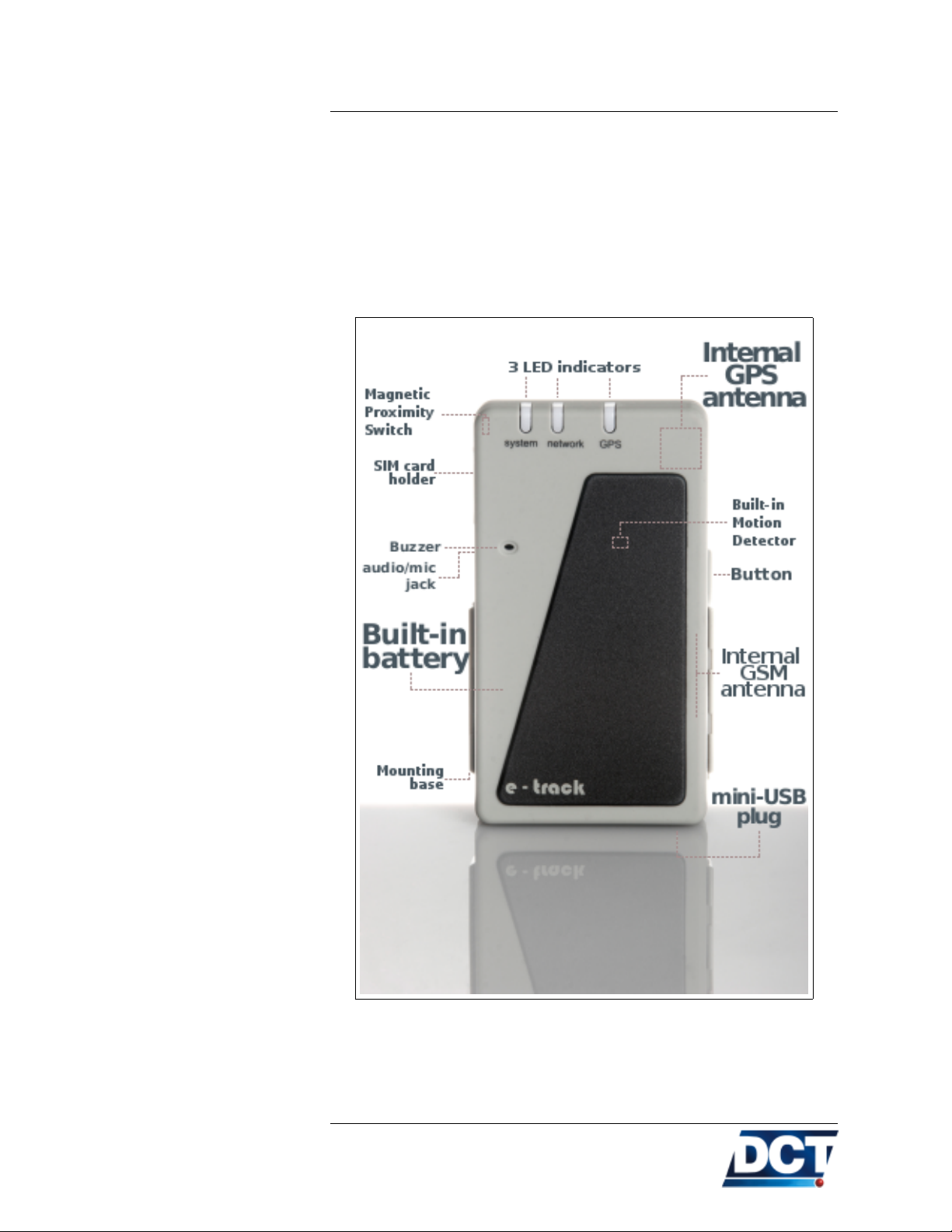
1 About e-track
TM
e-trackTMis a portable battery-powered GPS-tracking device designed
to interact remotely with Automated Location systems (Tracking
Servers) or with end-users by using the GSM/GPRS cellular net-
work as communication media. e-trackTMmay be installed or carried
on a vehicle whose geographical position and/or state is desired to
be remotely monitored. It can also be attached to cargo material to
secure assets. A person carrying this device can also be located by a
Personnel Logistic System.
The geographical position is taken from the unit’s built-in GPS receiver which gives information on geo-position, velocity, heading,
time-date, acceleration, altitude. Communication to and from the
device is achieved with its built-in GSM/GPRS communication processor. This enables the unit to be reached via TCP and/or UDP
(GPRS) and/or via SMS queries or Voice calls (GSM). In a similar
manner, the unit automatically communicates with an Automated
Tracking System via TCP/UDP and/or SMSs or it can also communicate with mobile numbers via SMS and/or voice calls.
e-trackTMhas a general purpose button which can be used for several
functions depending on one-click or two-click usages. These functions
may be defined by an user’s configuration. A built-in magnetic switch
is activated when a magnet is near the device. This switch can be
used as an alarm trigger when removing the device from a location
or it also enables e-trackTMto be used as a box-open detector when
attaching the device to a box which normally will remain closed. The
type of reports and actions triggered by this switch as well as the
one-click, two-click button presses actions are very flexible and may
be controlled by the user.
The unit has three LED indicators which give information on GPS
state, GSM/GPRS state and on general status. It has a buzzer for
built-in audible alerts and user-defined alerts.
A built-in battery allows the unit to work at full power for 12 to
15 hours depending on the reporting criteria and on network conditions. The unit can also work on alarm mode which allows the unit
to run on battery for 30 days. On alarm mode the unit can be programmed to switch to full power and report based on a time/date
1.1 Features
1.1. FEATURES
or on a time interval. It can also be kicked-out of alarm mode by a
change in the magnetic proximity switch state.
First-time configuration is performed throughout USB communication. The USB cable is also used as the main power source for battery
charging.
A brief description of the unit’s features is presented next.
16

1.1.1 Built-in Battery
1.1. FEATURES
e-trackTM’s built-in Li-On battery allows the unit to work on permanentpower or battery-power scenarios. The battery can be charged with
a computer via USB connection. By using accessories it can also be
charged from a wall outlet or from a vehicle’s battery. The time-tocharge depends on the type of charger. A 1400mA power supply will
charge the battery in 1 hour and 30 minutes. The duration of the
battery depends on many factors like:
• Frequency of the unit’s reporting.
• Network conditions: Poor network signal demands more power
from the unit.
• Battery condition: At full charge, mid-charge, etc.
Having the back-up battery at full charge on good network conditions
the measured durations are:
• 14 hours at full rate GPRS transmission: Having the unit re-
porting to an IP-type destination on a 1 minute basis. Depending on reporting criteria and on network conditions the battery
lasts between 12 and 16 hours.
• 30 days OFF (alarm mode) with the possibility of setting the
unit to automatically turn ON and report on a date/time, button press, magnetic switch sense or motion detection. The unit
may be configured to remain OFF and periodically turn ON,
report and go OFF again. The duration of the battery will
depend then on the period of report:
With an ON time of 2 minutes:
Period (OFF time) Duration
Reporting every 30 minutes 7.2 days
Reporting every hour 11.4 days
Reporting every 2 hours 16.42 days
Reporting every 6 hours 23.46 days
Reporting every 12 hours 26.32 days
With an ON time of 5 minutes:
Period (OFF time) Duration
Reporting every 30 minutes 3.65 days
Reporting every hour 6.14 days
Reporting every 2 hours 9.94 days
Reporting every 6 hours 17.74 days
Reporting every 12 hours 22.25 days
With an ON time of 10 minutes:
17

Warning:
1.1. FEATURES
Period (OFF time) Duration
Reporting every 30 minutes 2.2 days
Reporting every hour 3.65 days
Reporting every 2 hours 6.14 days
Reporting every 6 hours 12.69 days
Reporting every 12 hours 17.74 days
.
The ON time is configurable and it is very important not only
for battery duration as it is also the time-window the unit has
to calculate its GPS position and transmit an event. This value
can be lowered as long as good GPS and GPRS conditions are
present, otherwise the generated report may not contain valid
GPS data and/or it could never be transmitted on real-time. See
the Extending Battery duration section on the Operation chapter for information on how to use this value in the most efficient
manner.
The battery state may be consulted at any time with the XABS message, see the TAIP reference for more information. Also, an audible
alert indicates a low-battery condition1.
1.1.2 Built-in Cellular and GPS antennas
Having both antennas already inside the unit makes e-trackTMto be
easily installed and changed from one location to another making it
a real portable tracker. The only cable that may need to be attached
to the device is its main power source (USB cable).
1.1.3 USB connection (mini-USB port)
A mini-USB connector is used to configure the unit. It is also the
unit’s main power source used to charge the battery or to use e-
trackTMon permanent-power configurations such as a permanent ve-
hicle installation. The e-trackTM’s Windows Driver allows communication to the unit to be done via a Virtual Serial COM Port.
1.1.4 Voice support (GSM)
An audio jack for non-balanced hands-free audio system is provided
to initiate and receive phone calls with the unit.
1
Audible alerts can be turned OFF
18
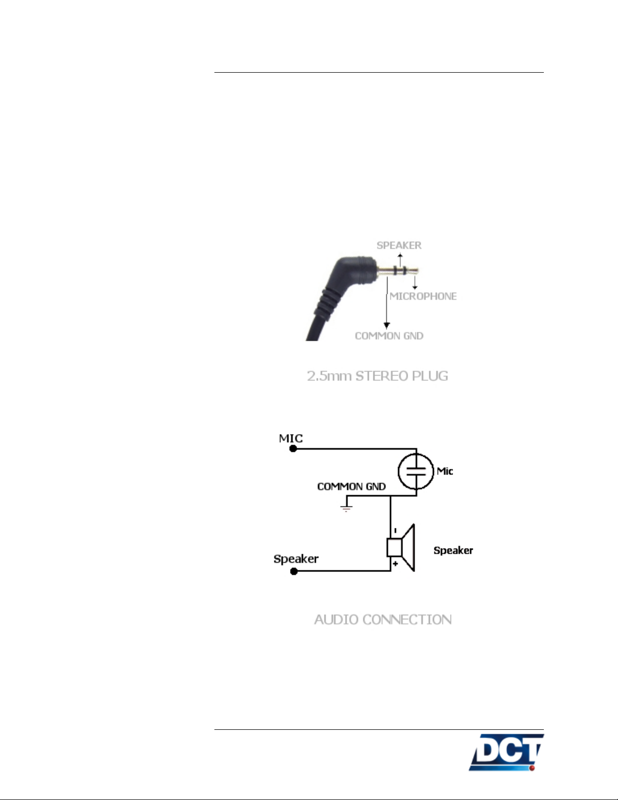
Audio jack
1.1. FEATURES
The audio connector is designed to connect a non-balanced hands-free
audio system.
See the Specifications section for information on the type of speaker
and microphone that can be used.
The connector is designed to use a 2.5mm stereo plug with the following configuration:
A non-balanced speaker-microphone connection must be as follows:
Most popular cellular phones’ hands-free that use a 2.5mm stereo plug
are compatible with this design.
19

1.1. FEATURES
1.1.5 SMS support (GSM)
When the unit is registered on the GSM network in can send and
receive SMSs. This feature is used to send user-defined event’s text
to phone numbers, TAIP reports to SMPP servers and to receive
commands or queries to interact with the unit over-the-air. See the
Operation and Configuration chapters.
1.1.6 TCP and UDP support (GPRS)
The unit may send its reports via GPRS to IP hosts using TCP
and/or UDP transport protocols. The unit may work with Destina-
tions on TCP and with Destinations on UDP at the same time. As
an special feature, UDP may be used with a confirmation mechanism
to achieve reliability at minimum cost.
1.1.7 Over the air control/consult (GSM/GPRS)
The unit can be controlled/consulted remotely via GPRS (TCP or
UDP) and/or via GSM by means of SMS messages.
1.1.8 Communication buffer
e-trackTM’s will start saving events’ reports whenever one or more
Destinations get unreachable. The buffer’s capacity is 1137 events.
This capacity leads to a approximately 4 days of data recording when
using a 5-minute, time-only report configuration.
1.1.9 DNS lookup
IP-type Destinations can be defined with a numeric IP address or
with a host name. e-trackTM’s will use the carrier’s DNS servers to
resolve names. This feature is very useful when the IP-host(s) resides
on an IP-changing environment.
1.1.10 Turn-by-turn report
By tracking the device’s GPS-heading change, a turn-by-turn report
can be achieved. This leads to detailed tracking of a device’s route
and also to a reduction of unnecessary reports on long straight roads
and highways. This serves as an alternative to time-only and timeor-distance reports.
1.1.11 IMEI as ID
This feature allows the unit to tag every reported message with the
unit’s IMEI. This eases the management of unit’s as the ID number
does not require to be programmed and it is a unique number that
20

1.1.12 Status LEDS
Note:
1.1. FEATURES
can’t be reused or shared with another unit. Also, this number can
not be deleted or changed.
Three LED indicators provide information on GSM/GPRS Network
status, GPS data-quality and on General unit’s Status. Each LED
normally indicates unit’s status except when in Auto-OFF mode: After one minute of a button press, magnetic switch change, or charger
connection/disconnection event all LEDs go OFF and system LED
starts blinking very shortly every 5 seconds. This is an energy saving
state where LED indicators do not reflect status of the unit. To make
all three LEDs show unit’s status again press the button once.
A single-button press on the Auto-OFF state will only make the
unit enable LED indicators so that state of the unit can be known.
Hence, a button-pressed event is not generated by this button
press. Only button presses done out of LEDS-Auto-OFF state
are considered a button-press event.
system (Red)
This feature is controlled by a configuration command that can be set
to instruct the unit to never use LEDs-Auto-OFF mode. The default
state is to use LEDs-Auto-OFF mode.
This is a general status indicator:
• SOLID: Indicates that the unit is powered by the USB cable
and the battery is fully charged.
• BLINK (when connected to the USB cable: 1sec-ON, 0,1sec-
OFF): Indicates that the battery is being charged.
• BLINK (when connected to the USB cable: 1sec-ON then two
0,1sec-OFF pulses.): Indicates that the battery charging process is initializing. Unit should not remain in this state for more
than 20 seconds.
• BLINK (when not connected to the USB cable: 0.3sec-ON,
4sec-OFF): Indicates that the battery has less than 25% of its
charge capacity.
• BLINK (when not connected to the USB cable: two 0.3sec-ON
pulses then 4sec-OFF): Indicates that the battery has between
25% and 50% of its charge capacity.
21

1.1. FEATURES
• BLINK (when not connected to the USB cable: three 0.3sec-
ON pulses then 4sec-OFF): Indicates that the battery has between 50% and 75% of its charge capacity.
• BLINK (when not connected to the USB cable: four 0.3sec-ON
pulses then 4sec-OFF): Indicates that the battery has between
75% and 100% of its charge capacity.
• BLINK (short short blink every 5 seconds): The unit is ON
and it is in LEDs-Auto-OFF mode. In this mode the other
LEDs do not reflect any status, they are OFF saving energy.
Press the button once to see LEDs’ state. See the introduction
above.
• OFF If all three indicators are OFF the unit is OFF. If any
other led is ON or blinking, this indicates a diagnostics state.
• BLINK (fast): This is an user-defined indication. It is used
by the user to reflect any state configured on a configuration
script. For example, e-track Configuration Assistant software
configures the unit so that system led blinks fast when a geofence alarm is set.
network (Green)
GPS (Yellow)
It is a GSM/GPRS/TCP indicator.
As long as the system LED is not completely OFF, or in short-blink
mode (LEDs-Auto-OFF mode) this LED indicates:
• SOLID: The unit is registered on GSM, GPRS and all TCP
sockets are open.
• BLINK (fast): The unit is registered on GSM and GPRS but
a TCP socket is not open.
• BLINK (slow): e-trackTMis registered on GSM but a GPRS
session has not been established.
• OFF: e-trackTMis not registered on the cellular network.
GPS data quality can be deduced from this indicator.
As long as the system LED is not completely OFF, or in short-blink
mode (LEDs-Auto-OFF mode) this LED indicates:
• ON: GPS is doing fixes and PDOP is low2. This indicates a
2
The default PDOP threshold is 5. See the XADO command.
22

1.1.13 Buzzer
1.1. FEATURES
good GPS condition (sky view is enough) and the GPS data is
recent and accurate.
• BLINK(1sec-ON, 0,1sec-OFF): Doing position fixes but PDOP
is to high. GPS data is recent and available but it may not be
accurate.
• OFF: Not doing position fixes. Less than 3 satellites in view.
GPS data is not recent or it is unavailable.
See the Checking GPS quality section on the Operation chapter for
more information.
See an interactive explanation at:
http://digitalcomtech.com/ledguidefrmt.html
e-trackTMhas audible pre-set and user-set alerts. Pre-set alerts give
information on low-battery condition, button press confirmation, system (re)start, incoming voice call. User-set alerts are combined with
the unit’s Event Machine to add interaction with the person o vehicle
being tracked. All type of audible alerts may be turned off with a
main buzzer-off command.
1.1.14 Button
A multi-purpose button is provided to turn on/off the unit, activate
a geo-fence alarm3, pick up or generate a voice call, generate reports,
etc. It can be used as a trigger for any action set on the Event
Machine.
1.1.15 Magnetic proximity switch
By using an external magnet, this internal magnetic field detector can
be used to detect when the unit is removed from a special location or
when a container’s door or box is opened.
1.1.16 Internal SIM card slot
The SIM card holder is located inside the unit and it is accessible
from a dedicated compartment hold by a single screw. e-track
works with 1.8V. and 3V. SIM cards.
3
This requires an special configuration which can be made with the Assisted
Configuration
TM
23

1.1.17 Event Reporting
1.1. FEATURES
e-trackTMhas the ability to interpret complex user-defined reporting
criteria to track normal, as well as exceptional situations. This is
called Event Report and it is mainly done via the Event Machine
included in the unit’s firmware.
This allows to create scenarios that include the boolean combination
of the following variables:
• 30 Polygon-defined geographical regions (50 points each).
• 70 Circular geographical regions.
• 10 Speed limits.
• 10 Time windows (dates’ intervals).
• one-click and two-click button press situations.
• Magnetic proximity switch.
• 20 Counters for traveled distance, time and event counting.
• 5 Heading change deltas (turn by turn report).
• 3 Battery level thresholds.
• 10 User signals to create complex reports.
• The fixed signals:
– Main power detection.
– GPS Fix state.
– GPS-PDOP too high detection.
– GSM roaming state.
– GSM registration state.
– GPRS registration state.
– GPRS attach state.
– TCP connections’ state indicators.
– Software reset indicator.
– Voice call state indicators.
– Low-battery signal.
1.1.18 Built-in Motion Detector
e-trackTMhas a Built-in Motion Detector. This Motion Detector is
used for the detection of movement by means of a omnidirectional
24

1.1. FEATURES
micro vibration sensor. This allows the user to create configuration
scripts that help e-trackTMsave energy and extend the battery duration and also helps to reduce the bandwidth usage as it can be
configured to stop reporting when no movement is detected.
25
1.2 Contents of package
1.2. CONTENTS OF PACKAGE
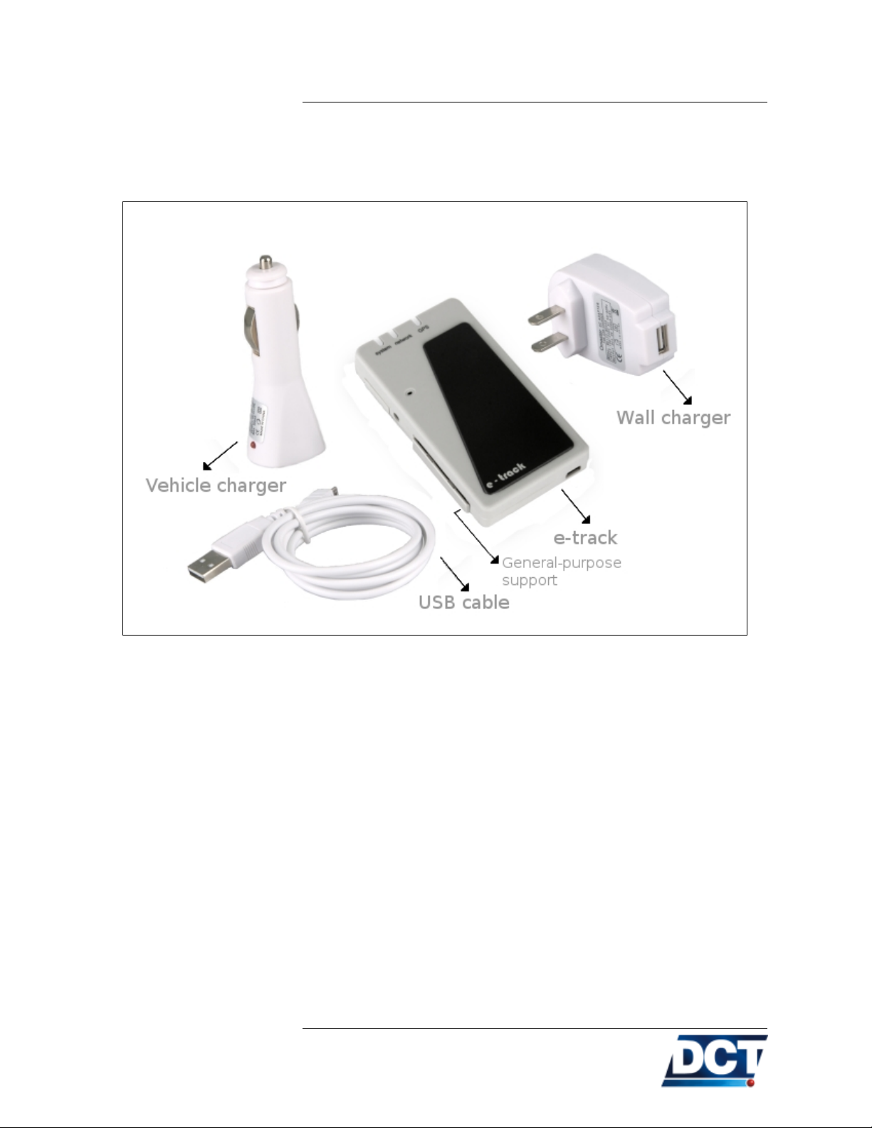
Inside e-trackTM’s box you will find the following content:
• An e-trackTM.
• USB to mini-USB cable. This cables is used to communicate
with the unit and also to charge the unit’s battery.
• A 120V to USB power converter. Use this to power up the unit
from a wall outlet working at 120V.
• A 12/24V to USB vehicle-lighter converter. Use this to power
up the unit with a vehicle lighter outlet working at 12 or 24
volts.
• A general-purpose support with suction cups provided for glass-
fixing.
26
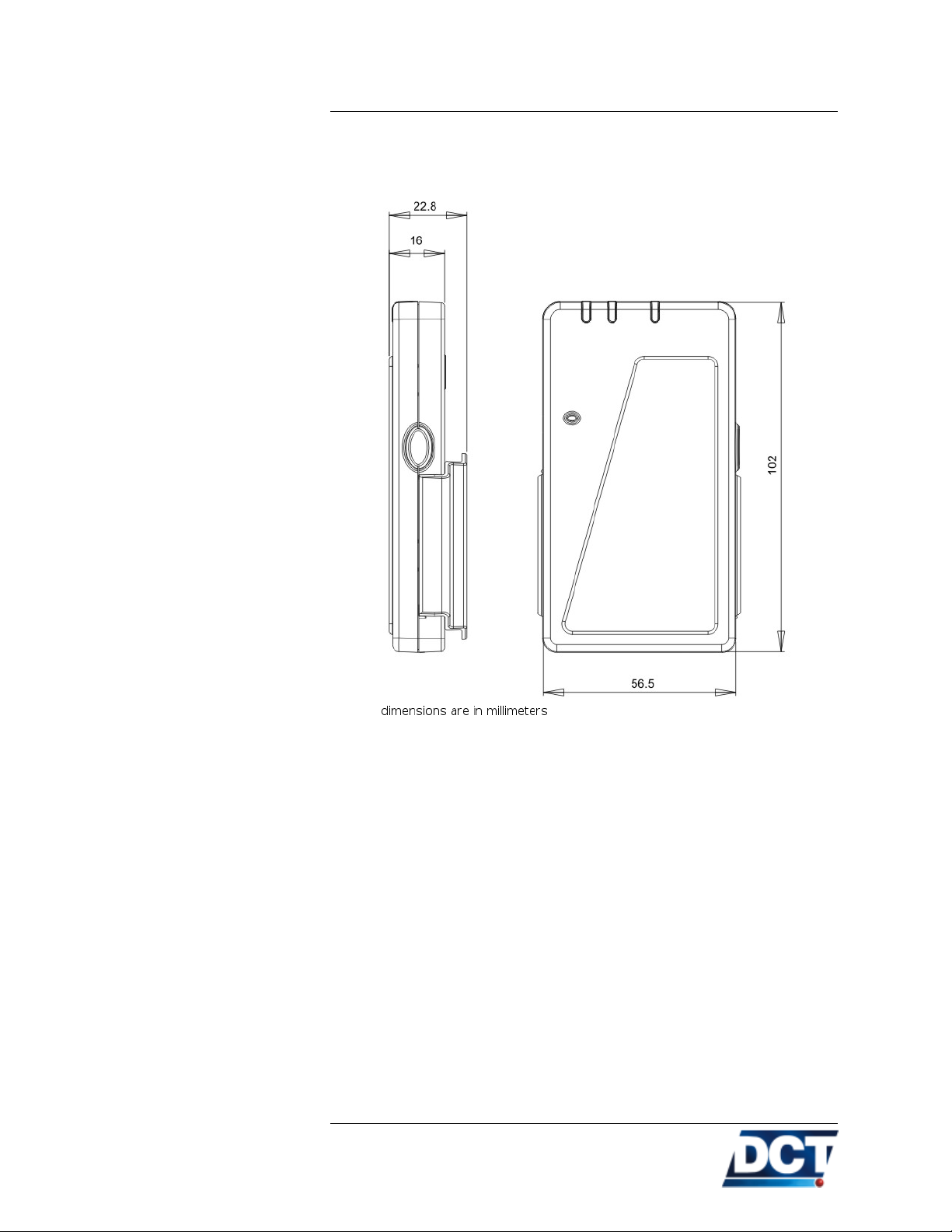
1.3 Specifications
1.3.1 Dimensions
1.3. SPECIFICATIONS
1.3.2 Environment
1.3.3 Power
• Operating: −20◦C to +55◦C
• Storage: −30◦C to +85◦C
• Humidity: Up to 95% non-condensing.
• DC Voltage: 4.8V - 5.25V
• Current consumption:
– Depending on the battery charge: 100mA to 1400mA. The
power supply must provide a minimum of 500mA to guarantee full battery charging. A 1400mA power supply is
recommended for faster battery charging.
27

1.3. SPECIFICATIONS
1.3.4 Audio
1.3.5 GSM/GPRS module
• Supports non-balanced mic-speaker connection.
• 2.5mm Stereo audio jack.
• The external speaker impedance must be: 32ohms.
• External microphone: Electret type.
• Frequencies: 850/1900/900/1800 Mhz.
• Full duplex communication.
• Automatic start up.
• SIM Card: 1.8 Volts and 3 Volts.
• SIM Card PIN: Programmed by user one time, automatically in-
troduced onward. PIN saved on Non-Volatile memory.
• Receiver parameters:
– GSM850 Reference Sensitivity = -104 dBm Static and TUHigh.
– E-GSM900 Reference Sensitivity = -104 dBm Static and
TUHigh.
– DCS1800 Reference Sensitivity = -102 dBm Static and
TUHigh.
– PCS1900 Reference Sensitivity = -102 dBm Static and TUHigh.
– Selectivity @ 200 kHz : > +9 dBc
– Selectivity @ 400 kHz : > +41 dBc
– Linear dynamic range: 63 dB
– Co-channel rejection : >= 9 dBc
• Transmitter parameters:
– Maximum output power (EGSM and GSM850): 33 dBm
+/- 2dB at ambient temperature
– Maximum output power (GSM1800 and PCS1900): 30
dBm +/- 2dB at ambient temperature
– Minimum output power (EGSM and GSM850): 5 dBm
+/- 5dB at ambient temperature
– Minimum output power (GSM1800 and PCS1900): 0 dBm
+/- 5dB at ambient temperature
28
 Loading...