

DCT Antares SB User Manual

Antares SB
Digital Communications Technologies
TM
GSM User’s Manual (FW 5.30)
September 9, 2009

.
Copyright
This manual is copyrighted. All type of reproduction of its content must be authorized by Digital
Communications TechnologiesTM.
Document information
Version: 1.00
Type: Release.
Date of release: 08-09-09
History:

Version Comments
5.30-1.00
08-09-09
First release for Antares FW 5.30.
Added info. on Garmin Devices Support.
Added info. on ORBCOMM Satellite Modems Support.
Added info. on OBD Support.
Added info. on SMS Alias.
Added info. on SMS Gateway.
Added info. on Virtual Odometer.
Added info. on Authentication Mechanism.
Added info. on Event Machine.
Added info. on Event Definition.
Added info. on Event Message.
Added info. on Reset message.
Added info. on TAIP Console.
Added info. on Regions Report.
Added info. on Store & Forward Thresholds.
Added info. on MDT Mode.
Added info. on Driving Metrics.
Added info. on Reporting Mode.
Added info. on Diagnostic Message.
Added info. on Silent Actions.
Changed info. on GPS Module Specifications.
Changed info. on Status.
Changed info. on Extended-EV Message Formats.
Changed info. on IMEI as ID.
Changed info. on UDP Origin Port.
Changed info. on UDP Server Port.
Changed info. on Counters, Timers, Distancers.
Changed info. on Registration Parameters.
Changed info. on Firmware Upgrade (Over the air).
Changed info. on Local Lock.
Changed info. on Create Circular Region “Here”.
Changed info. on Destinations’ set.
Changed info. on TAIP Console Sniffer.
Changed info. on Keep Alive.
Changed info. on Voice Call End.
Changed info. on Destinations’ Set.
Changed info. on Altitude.
Changed Limited Warranty info.
Corrected example on Using Acceleration Signals.
Special Note
This manual applies to the GSM version of the Antares SBTM.
Firmware version
This manual applies to firmware version 5.30 of the GSM version of the Antares SBTM. You can consult the unit’s
firmware version with the >QVR< TAIP command.
2

Regulatory Compliance
FCC
This product operates with Wavecoms Q24PL transmitter.
FCC Parts 22H and 24E are granted to the Wavecom Q24PL under FCC identifier O9EQ24PL001.
The antenna gain, including cable loss, must not exceed 3 dBi at 1900 MHz / 1.4 dBi at 850
MHz for mobile operating configurations and 7 dBi at 1900 MHz / 1.4 dBi at 850 MHz for fixed
mounted operations, as defined in 2.1091 and 1.1307 of the rules for satisfying RF exposure compliance.
In addition, the antenna used for this device must be installed to provide a separation distance of
at least 20 cm from all persons.

GARMIN AUTHORIZED PARTNER
Digital Communications Technologies LLC is a Garmin authorized partner. Founded in 1989,
Garmin is a pioneer in Global Positioning System (GPS) devices and the worldwide leader in the
design, manufacture and sale of GPS equipment. The company has built and sold millions of GPS
products that serve the automotive, aviation, marine, consumer, wireless, OEM, and general recreation markets. For more information visit http://www8.garmin.com/solutions/pnd/partners.jsp

LIMITED WARRANTY
Digital Communications Technologies warrants the original purchaser that for a period of twelve
(12) months from the date of purchase, the product shall be free of defects in materials and workmanship under normal use. During the warranty period, Digital Communications Technologies
shall, at its option, repair or replace any defective product upon return of the product to its facilities, at no charge for labor and materials. Any replacement and/or repaired parts are warranted
for the remainder of the original warranty or ninety (90) days, whichever is longer. The original
owner must promptly notify Digital Communications Technologies in writing that there is defect
in material or workman-ship. Such written notice must be received in all events prior to expiration
of the warranty period.
International Warranty
The warranty for international customers is the same as for any customer within the United States,
with the exception that Digital Communications Technologies shall not be responsible for any customs fees, taxes, or VAT that may be due.
Warranty Procedure
To obtain service under this warranty, please return the item(s) in question to the point of purchase. All authorized distributors and dealers have a warranty program. Anyone returning goods
to Digital Communications Technologies must first obtain an authorization number. Digital Communications Technologies will not accept any shipment whatsoever for which prior authorization
has not been obtained.
Conditions to Void Warranty
This warranty applies only to defects in parts and workmanship relating to normal use. It does
not cover:
• Damage incurred in shipping or handling
• Damage caused by disaster such as fire, flood, wind, earthquake or lightning
• Damage due to causes beyond the control of Digital Communications Technologies such as
excessive voltage, mechanical shock or water damage
• Damage caused by unauthorized attachment, alterations, modifications or foreign objects
• Damage caused by peripherals unless such peripherals were supplied by Digital Communica-
tions Technologies
• Defects caused by failure to provide a suitable installation environment for the products
• Damage caused by use of the products for purposes other than those for which it was designed
• Damage from improper maintenance
• Damage arising out of any other abuse, mishandling or improper application of the products
Digital Communications Technologiess liability for failure to repair the product under this warranty after a reasonable number of attempts will be limited to a replacement of the product, as the
exclusive remedy for breach of warranty. Under no circumstances shall Digital Communications

Technologies be liable for any special, incidental, or consequential damages based upon breach of
warranty, breach of contract, negligence, strict liability, or any other legal theory. Such damages
include, but are not limited to, loss of profits, loss of the product or any associated equipment, cost
of capital, cost of substitute or replacement equipment, facilities or services, down time, purchasers
time, the claims of third parties, including customers, and injury to property.
Disclaimer of Warranties
This warranty contains the entire warranty and shall be in lieu of any and all other warranties,
whether expressed or implied (including all implied warranties of merchantability or fitness for a
particular purpose) And of all other obligations or liabilities on the part of Digital Communications Technologies. Digital Communications Technologies neither assumes nor authorizes any other
person purporting to act on its behalf to modify or to change this warranty, nor to assume for it
any other warranty or liability concerning this product. This disclaimer of warranties and limited
warranty are governed by the laws of the State of Florida, USA.
WARNING
Digital Communications Technologies recommends that the entire system be completely tested on
a regular basis. However, despite frequent testing, and due to, but not limited to, criminal tampering or electrical disruption, it is possible for this product to fail to perform as expected.
Out of Warranty Repairs
Digital Communications Technologies will at its option repair or replace out-of-warranty products
which are returned to its factory according to the following conditions. Anyone returning goods
to Digital Communications Technologies must first obtain an authorization number. Digital Communications Technologies will not accept any shipment whatsoever for which prior authorization
has not been obtained. Products which Digital Communications Technologies determines to be
repairable will be repaired and returned. A set fee which Digital Communications Technologies
has predetermined and which may be revised from time to time, will be charged for each unit
repaired. Products which Digital Communications Technologies determines not to be repairable
will be replaced by the nearest equivalent product available at that time. The current market price
of the replacement product will be charged for each replacement unit.
6

Contents
0.1 Scope . . . . . . . . . . . . . . . . . . . . . . . . . . . 19
0.2 Organization . . . . . . . . . . . . . . . . . . . . . . . 19
0.3 Technical Assistance . . . . . . . . . . . . . . . . . . . 20
1 About the Antares SB
TM
1.1 Features . . . . . . . . . . . . . . . . . . . . . . . . . . 21
1.1.1 Analog to Digital Converter . . . . . . . . . . . 21
1.1.2 Discrete Inputs and Outputs . . . . . . . . . . 21
1.1.3 Optional Back-up Battery . . . . . . . . . . . . 22
1.1.4 Voice support . . . . . . . . . . . . . . . . . . . 22
1.1.5 SMS support . . . . . . . . . . . . . . . . . . . 22
1.1.6 TCP and UDP support . . . . . . . . . . . . . 22
1.1.7 Over the air control/consult . . . . . . . . . . . 22
1.1.8 Over the air upgrade . . . . . . . . . . . . . . . 22
1.1.9 Versatile RS-232 communication . . . . . . . . 23
1.1.10 Communication buffer . . . . . . . . . . . . . . 23
1.1.11 Automatic outputs’ control . . . . . . . . . . . 23
1.1.12 DNS lookup . . . . . . . . . . . . . . . . . . . . 23
21
1.1.13 Turn-by-turn report . . . . . . . . . . . . . . . 23
1.1.14 Driving metrics . . . . . . . . . . . . . . . . . . 23
1.1.15 GPS Back Log and Acceleration . . . . . . . . 24
1.1.16 IMEI as ID . . . . . . . . . . . . . . . . . . . . 24
1.1.17 Cell ID reporting . . . . . . . . . . . . . . . . . 24
1.1.18 Molex-type connectors . . . . . . . . . . . . . . 24
1.1.19 SMA Reverse polarity GPS antenna connector 24
1.1.20 Event Reporting . . . . . . . . . . . . . . . . . 24

Contents
1.2 Contents of package . . . . . . . . . . . . . . . . . . . 26
1.3 Front side description . . . . . . . . . . . . . . . . . . 27
1.3.1 RS-232 port . . . . . . . . . . . . . . . . . . . . 27
1.3.2 SIM card slot . . . . . . . . . . . . . . . . . . . 28
1.3.3 LEDs . . . . . . . . . . . . . . . . . . . . . . . 28
1.3.4 AUDIO jack . . . . . . . . . . . . . . . . . . . 29
1.4 Back side description . . . . . . . . . . . . . . . . . . . 30
1.4.1 GSM Antenna connector . . . . . . . . . . . . . 30
1.4.2 GPS Antenna connector . . . . . . . . . . . . . 30
1.4.3 I/O molex-type connector . . . . . . . . . . . . 30
1.4.4 Power/ignition molex-type connector . . . . . . 31
1.5 Specifications . . . . . . . . . . . . . . . . . . . . . . . 33
1.5.1 Dimensions . . . . . . . . . . . . . . . . . . . . 33
1.5.2 Environment . . . . . . . . . . . . . . . . . . . 33
1.5.3 Power . . . . . . . . . . . . . . . . . . . . . . . 33
1.5.4 Inputs/Ignition . . . . . . . . . . . . . . . . . . 34
1.5.5 Outputs . . . . . . . . . . . . . . . . . . . . . . 34
1.5.6 Analog To Digital Converter . . . . . . . . . . 34
1.5.7 Audio . . . . . . . . . . . . . . . . . . . . . . . 34
1.5.8 GSM/GPRS module . . . . . . . . . . . . . . . 35
1.5.9 GPS module . . . . . . . . . . . . . . . . . . . 36
1.5.10 GSM antenna connector . . . . . . . . . . . . . 37
1.5.11 GPS antenna connector . . . . . . . . . . . . . 38
2 Installation 39
2.1 Power Supply . . . . . . . . . . . . . . . . . . . . . . . 39
2.1.1 Vehicles with a main power switch . . . . . . . 39
2.2 Inputs detection . . . . . . . . . . . . . . . . . . . . . 43
2.3 Ignition detection . . . . . . . . . . . . . . . . . . . . . 43
2.4 Outputs . . . . . . . . . . . . . . . . . . . . . . . . . . 44
2.5 Connection diagrams . . . . . . . . . . . . . . . . . . . 46
8

Contents
3 Operation 48
3.1 Serial Port . . . . . . . . . . . . . . . . . . . . . . . . . 49
3.2 LEDs . . . . . . . . . . . . . . . . . . . . . . . . . . . 49
3.2.1 Power (Red) . . . . . . . . . . . . . . . . . . . 50
3.2.2 Signal (Orange) . . . . . . . . . . . . . . . . . . 50
3.2.3 Fix (Yellow) . . . . . . . . . . . . . . . . . . . . 51
3.2.4 On line (Green) . . . . . . . . . . . . . . . . . . 51
3.3 Inputs/Ignition . . . . . . . . . . . . . . . . . . . . . . 52
3.4 Outputs . . . . . . . . . . . . . . . . . . . . . . . . . . 53
3.5 Analog to Digital Converter . . . . . . . . . . . . . . . 54
3.6 Back-up Battery . . . . . . . . . . . . . . . . . . . . . 55
3.7 Sleep Mode . . . . . . . . . . . . . . . . . . . . . . . . 57
3.8 Over The Air . . . . . . . . . . . . . . . . . . . . . . . 57
3.8.1 Via IP hosts (GPRS) . . . . . . . . . . . . . . 57
3.8.2 Via SMS (GSM) . . . . . . . . . . . . . . . . . 60
3.8.3 Voice (GSM) . . . . . . . . . . . . . . . . . . . 61
3.9 TAIP console . . . . . . . . . . . . . . . . . . . . . . . 61
3.9.1 TAIP Message Format . . . . . . . . . . . . . . 61
3.9.2 Reporting messages . . . . . . . . . . . . . . . 64
3.9.3 Interacting . . . . . . . . . . . . . . . . . . . . 64
3.10 Remote host software . . . . . . . . . . . . . . . . . . 64
3.10.1 Working with TCP . . . . . . . . . . . . . . . . 65
3.10.2 Working with UDP . . . . . . . . . . . . . . . . 66
3.10.3 Working with SMS . . . . . . . . . . . . . . . . 67
3.11 Reports’ messages . . . . . . . . . . . . . . . . . . . . 68
3.11.1 Events’ Reporting Messages . . . . . . . . . . . 68
3.11.2 Responses to TAIP Commands Messages . . . 69
3.12 Reports’ buffer . . . . . . . . . . . . . . . . . . . . . . 70
3.13 GPS Back Log . . . . . . . . . . . . . . . . . . . . . . 71
3.14 Virtual Odometer . . . . . . . . . . . . . . . . . . . . . 71
3.15 Authentication Mechanism . . . . . . . . . . . . . . . 71
9

Contents
3.16 SMS Alias . . . . . . . . . . . . . . . . . . . . . . . . . 72
3.17 SMS Messages Gateway . . . . . . . . . . . . . . . . . 72
3.18 Garmin Devices Suppport . . . . . . . . . . . . . . . . 72
3.18.1 Setting up Antares SB
TM
. . . . . . . . . . . . 72
3.18.2 Data Flow Example . . . . . . . . . . . . . . . 74
3.18.3 Setting Up The Server . . . . . . . . . . . . . . 79
3.19 ORBCOMM Satellite Modems Support . . . . . . . . 79
3.19.1 Setting up Antares SBTMfor ORBCOMM Satel-
lite Modems . . . . . . . . . . . . . . . . . . . . 79
3.19.2 Operation . . . . . . . . . . . . . . . . . . . . . 80
3.19.3 Example . . . . . . . . . . . . . . . . . . . . . . 80
3.20 OBD Support . . . . . . . . . . . . . . . . . . . . . . . 82
3.21 Firmware Upgrade . . . . . . . . . . . . . . . . . . . . 83
3.21.1 Over The Air . . . . . . . . . . . . . . . . . . . 83
3.21.2 Upgrading locally . . . . . . . . . . . . . . . . . 85
3.22 TAIP DownloaderTMTool (Write/Read scripts) . . . . 85
3.22.1 Communicating locally with the Antares SB
TM
86
3.22.2 STEP 1. Selecting a COM port . . . . . . . . 86
3.22.3 STEP 2. Test Communication . . . . . . . . . 86
3.22.4 Write a Configuration Script . . . . . . . . . . 87
3.22.5 Read a Configuration Script . . . . . . . . . . . 88
3.22.6 Over The Air . . . . . . . . . . . . . . . . . . . 88
4 Configuration 89
4.1 *Unit’s ID . . . . . . . . . . . . . . . . . . . . . . . . . 90
4.2 *Enabling the unit on GSM and GPRS . . . . . . . . 90
4.2.1 SIM Card’s PIN for GSM registration . . . . . 91
4.2.2 Access Point Name (APN) for GPRS set up . . 92
4.3 *Destinations (DPs and DAs) . . . . . . . . . . . . . . 93
4.3.1 Destination Points (DPs) . . . . . . . . . . . . 93
4.3.2 Destination Addresses (DAs) . . . . . . . . . . 94
10

Contents
4.4 Reporting . . . . . . . . . . . . . . . . . . . . . . . . . 95
4.5 *Event Machine . . . . . . . . . . . . . . . . . . . . . . 96
4.5.1 Triggers . . . . . . . . . . . . . . . . . . . . . . 96
4.5.2 Actions . . . . . . . . . . . . . . . . . . . . . . 98
4.5.3 Events . . . . . . . . . . . . . . . . . . . . . . . 101
4.5.4 Signals . . . . . . . . . . . . . . . . . . . . . . . 102
4.5.5 Examples . . . . . . . . . . . . . . . . . . . . . 107
4.6 Using Polygonal Regions . . . . . . . . . . . . . . . . . 107
4.7 Using Circular Regions (geo-fences) . . . . . . . . . . . 108
4.8 Using Region ID Reports . . . . . . . . . . . . . . . . 109
4.9 Setting Speed Limits . . . . . . . . . . . . . . . . . . . 109
4.10 The Time And Distance criteria . . . . . . . . . . . . 110
4.11 Using Time Windows . . . . . . . . . . . . . . . . . . 111
4.12 Using Counters . . . . . . . . . . . . . . . . . . . . . . 111
4.13 Manipulating signals . . . . . . . . . . . . . . . . . . . 116
4.14 User signals . . . . . . . . . . . . . . . . . . . . . . . . 116
4.15 Using Heading Deltas (turn-by-turn report) . . . . . . 116
4.16 Driving Metrics (Acceleration, Max. Speed, etc) . . . 117
4.17 Using Acceleration signals . . . . . . . . . . . . . . . . 119
4.18 Voice calls . . . . . . . . . . . . . . . . . . . . . . . . . 120
4.19 Battery monitoring . . . . . . . . . . . . . . . . . . . . 120
4.20 Serial port devices . . . . . . . . . . . . . . . . . . . . 121
4.21 Analog to Digital Converter monitoring . . . . . . . . 123
4.22 Using a TCP/UDP keep-alive . . . . . . . . . . . . . . 123
4.23 IMEI as ID . . . . . . . . . . . . . . . . . . . . . . . . 123
4.24 Cell ID reporting . . . . . . . . . . . . . . . . . . . . . 124
4.25 Sleep mode . . . . . . . . . . . . . . . . . . . . . . . . 125
4.26 Restoring the unit . . . . . . . . . . . . . . . . . . . . 125
4.27 Resetting the unit . . . . . . . . . . . . . . . . . . . . 125
4.28 Using Scripts . . . . . . . . . . . . . . . . . . . . . . . 126
4.28.1 Creating an script from scratch . . . . . . . . . 127
11

Contents
4.28.2 Reading Scripts . . . . . . . . . . . . . . . . . . 127
4.28.3 Writing Scripts . . . . . . . . . . . . . . . . . . 128
4.28.4 Scripts Over The Air . . . . . . . . . . . . . . . 128
5 Scenarios and examples 130
5.1 Getting Started . . . . . . . . . . . . . . . . . . . . . . 130
5.1.1 Setting the unit’s ID . . . . . . . . . . . . . . . 130
5.1.2 Setting the APN and PIN . . . . . . . . . . . . 130
5.1.3 Creating a Destination Point (DP) . . . . . . . 131
5.1.4 Creating a Destination Address (DA) . . . . . 132
5.1.5 Creating a time-period criterion . . . . . . . . 132
5.1.6 Tiding a signal to an event . . . . . . . . . . . 133
5.1.7 Checking the host software/server . . . . . . . 133
5.1.8 Adding an Input report . . . . . . . . . . . . . 134
5.1.9 Script . . . . . . . . . . . . . . . . . . . . . . . 134
5.2 Adding SMS reporting . . . . . . . . . . . . . . . . . . 135
5.2.1 Create the SMS Destination Point . . . . . . . 135
5.2.2 Create a new Destination Address . . . . . . . 135
5.2.3 Change the Input report event definition . . . . 136
5.2.4 Create a SMS custom message . . . . . . . . . 136
5.2.5 Check the reported message . . . . . . . . . . . 136
5.2.6 Script . . . . . . . . . . . . . . . . . . . . . . . 137
5.3 Adding SMS interaction . . . . . . . . . . . . . . . . . 138
5.3.1 Query the unit with a SMS . . . . . . . . . . . 138
5.3.2 Set an output with a SMS . . . . . . . . . . . . 138
5.4 Adding voice interaction . . . . . . . . . . . . . . . . . 139
5.4.1 Make the unit accept a phone call . . . . . . . 139
5.4.2 Have the unit initiate a voice call . . . . . . . . 139
5.5 Ignition detection . . . . . . . . . . . . . . . . . . . . . 140
5.5.1 Script . . . . . . . . . . . . . . . . . . . . . . . 140
5.6 Speed violation (with warning) report . . . . . . . . . 141
12

Contents
5.6.1 Setting the speed limit . . . . . . . . . . . . . . 142
5.6.2 Start a counter . . . . . . . . . . . . . . . . . . 142
5.6.3 Creating the violation report . . . . . . . . . . 142
5.6.4 Something is missing... . . . . . . . . . . . . . . 142
5.6.5 Driving the LED . . . . . . . . . . . . . . . . . 142
5.6.6 Script . . . . . . . . . . . . . . . . . . . . . . . 143
5.7 START/STOP monitoring . . . . . . . . . . . . . . . . 144
5.7.1 Setting a low speed limit . . . . . . . . . . . . 145
5.7.2 Start a counter . . . . . . . . . . . . . . . . . . 145
5.7.3 Create the STOP report . . . . . . . . . . . . . 145
5.7.4 Create the START report . . . . . . . . . . . . 146
5.7.5 Something’s missing... . . . . . . . . . . . . . . 146
5.7.6 Script . . . . . . . . . . . . . . . . . . . . . . . 146
5.8 Safe engine turn off . . . . . . . . . . . . . . . . . . . . 148
5.8.1 Create the speed limit . . . . . . . . . . . . . . 149
5.8.2 Creating a timer . . . . . . . . . . . . . . . . . 149
5.8.3 Cutting the ignition . . . . . . . . . . . . . . . 149
5.8.4 Stopping the counter . . . . . . . . . . . . . . . 149
5.8.5 Restore the user signal . . . . . . . . . . . . . . 149
5.8.6 Script . . . . . . . . . . . . . . . . . . . . . . . 150
5.8.7 Operation . . . . . . . . . . . . . . . . . . . . . 152
5.9 Improving the periodic report . . . . . . . . . . . . . . 153
5.9.1 Script . . . . . . . . . . . . . . . . . . . . . . . 154
5.10 Reconnection event for TCP . . . . . . . . . . . . . . . 157
5.10.1 Script . . . . . . . . . . . . . . . . . . . . . . . 157
5.11 Main-power-loss alarm . . . . . . . . . . . . . . . . . . 160
5.11.1 Script . . . . . . . . . . . . . . . . . . . . . . . 160
5.12 Using the sleep mode . . . . . . . . . . . . . . . . . . . 160
5.13 Configuring/reading a distance counter . . . . . . . . . 161
5.14 Generating an extended-EV report . . . . . . . . . . . 161
13

Contents
6 Unit’s TAIP reference 163
6.1 (AL) Altitude . . . . . . . . . . . . . . . . . . . . . . . 164
6.2 (CP) Compact Position . . . . . . . . . . . . . . . . . 165
6.3 (DA) Destination Address . . . . . . . . . . . . . . . . 166
6.3.1 Examples . . . . . . . . . . . . . . . . . . . . . 167
6.4 (DP) Destination Point . . . . . . . . . . . . . . . . . 168
6.5 (ED) Event Definition . . . . . . . . . . . . . . . . . . 170
6.5.1 Examples . . . . . . . . . . . . . . . . . . . . . 172
6.6 (ER) Error Report . . . . . . . . . . . . . . . . . . . . 174
6.6.1 Example . . . . . . . . . . . . . . . . . . . . . . 174
6.7 (ET) Event Report, time only message . . . . . . . . . 175
6.8 (EV) Event Message . . . . . . . . . . . . . . . . . . . 176
6.9 (GC) Counters, Timers, Distancers . . . . . . . . . . . 179
6.9.1 Counters’ commands . . . . . . . . . . . . . . . 180
6.9.2 Examples . . . . . . . . . . . . . . . . . . . . . 180
6.10 (GF) GPIOs’ function (I/O) . . . . . . . . . . . . . . . 182
6.11 (GS) Speed Limit . . . . . . . . . . . . . . . . . . . . . 183
6.12 (GT) Time Window . . . . . . . . . . . . . . . . . . . 184
6.13 (GR) Regions . . . . . . . . . . . . . . . . . . . . . . . 185
6.13.1 Special cases . . . . . . . . . . . . . . . . . . . 186
6.13.2 Regions’ creation examples . . . . . . . . . . . 186
6.14 (ID) Identification . . . . . . . . . . . . . . . . . . . . 191
6.15 (MS) Memory Session . . . . . . . . . . . . . . . . . . 192
6.16 (MT) MDT Mode . . . . . . . . . . . . . . . . . . . . 193
6.17 (PV) Position-velocity . . . . . . . . . . . . . . . . . . 194
6.18 (RF) Radio Frequency module configuration . . . . . . 195
6.19 (RM) Reporting Mode . . . . . . . . . . . . . . . . . . 196
6.20 (RP) Registration Parameters (Cellular Network) . . . 197
6.21 (RT) Reset message . . . . . . . . . . . . . . . . . . . 199
6.22 (SS) Signal Status . . . . . . . . . . . . . . . . . . . . 200
6.22.1 Examples . . . . . . . . . . . . . . . . . . . . . 200
14

Contents
6.23 (ST) Status . . . . . . . . . . . . . . . . . . . . . . . . 202
6.24 (TM) Time and Date . . . . . . . . . . . . . . . . . . . 203
6.25 (TD) Time and Distance signals configuration . . . . . 204
6.26 (TX) Text Message . . . . . . . . . . . . . . . . . . . . 206
6.26.1 Escape sequences . . . . . . . . . . . . . . . . . 206
6.26.2 Garmin Mode Messages . . . . . . . . . . . . . 206
6.27 (VR) Version number . . . . . . . . . . . . . . . . . . 211
6.28 (XAAC) Analog to Digital converter . . . . . . . . . . 212
6.29 (XAAU) Challenge Text . . . . . . . . . . . . . . . . . 213
6.30 (XABS) Battery Status . . . . . . . . . . . . . . . . . 214
6.31 (XACE) Cell Environment . . . . . . . . . . . . . . . . 215
6.32 (XACR) Counter Report . . . . . . . . . . . . . . . . . 216
6.32.1 Reported Message . . . . . . . . . . . . . . . . 216
6.33 (XACT) Communication Test . . . . . . . . . . . . . . 217
6.34 (XADM) Diagnostic Message . . . . . . . . . . . . . . 218
6.35 (XADP) Destination Points . . . . . . . . . . . . . . . 221
6.35.1 IP-type destinations . . . . . . . . . . . . . . . 221
6.35.2 Telephone destinations . . . . . . . . . . . . . . 221
6.36 (XAEF) Extended-EV message Formats . . . . . . . . 223
6.37 (XAFU) Firmware Upgrade (Over the air) . . . . . . . 225
6.38 (XAGA) ADC levels . . . . . . . . . . . . . . . . . . . 226
6.39 (XAGB) Back-up Battery levels . . . . . . . . . . . . . 227
6.40 (XAGF) Store & Forward Thresholds . . . . . . . . . 228
6.41 (XAGH) Heading deltas . . . . . . . . . . . . . . . . . 229
6.42 (XAGM) Garmin Mode . . . . . . . . . . . . . . . . . 230
6.42.1 (XAGMI) Consult Garmin Device General Infor-
mation . . . . . . . . . . . . . . . . . . . . . . . 231
6.42.2 (XAGMKI) Garmin Mode Driver ID . . . . . . . 231
6.42.3 (XAGMKSA) Garmin Mode Add Driver Status . 232
6.42.4 (XAGMKSD) Garmin Mode Delete Driver Status 233
6.42.5 (XAGMKS) Garmin Mode Change Driver Status 233
15

Contents
6.42.6 (XAGMR) Garmin Mode Add or Delete Canned
Replies . . . . . . . . . . . . . . . . . . . . . . 234
6.42.7 (XAGMRS) Garmin Mode Canned Reply Text
Message . . . . . . . . . . . . . . . . . . . . . 234
6.42.8 (XAGMS) Garmin Mode Stop Message . . . . . 235
6.42.9 (XAGMCS) Garmin Mode Change Stop Message
Status . . . . . . . . . . . . . . . . . . . . . . . 237
6.42.10 (XAGMTS) Garmin Mode Text Send . . . . . . . 238
6.42.11 (XAGMT) Garmin Mode Message Status . . . . 239
6.42.12 (XAGMTA) Garmin Mode Set Canned Message . 240
6.42.13 (XAGMTD) Garmin Mode Delete Canned Message240
6.42.14 (XAGMX) Delete Fleet Management Protocol Re-
lated Data . . . . . . . . . . . . . . . . . . . . . 241
6.43 (XAGN) Acceleration Limits . . . . . . . . . . . . . . 242
6.44 (XAGP) GPRS Pause . . . . . . . . . . . . . . . . . . 243
6.45 (XAGR) Circular Regions . . . . . . . . . . . . . . . . 244
6.46 (XAID) IMEI as ID . . . . . . . . . . . . . . . . . . . 245
6.47 (XAIM) IMEI consult . . . . . . . . . . . . . . . . . . 246
6.48 (XAIO) Input, Outputs consult . . . . . . . . . . . . 247
6.49 (XAIP) IP address . . . . . . . . . . . . . . . . . . . . 248
6.50 (XAIR) Create Circular Region “here” . . . . . . . . 249
6.51 (XAIT) Driving Metrics . . . . . . . . . . . . . . . . . 250
6.52 (XAKA) Keep Alive . . . . . . . . . . . . . . . . . . . 251
6.53 (XAKL) GPS Back Log . . . . . . . . . . . . . . . . . 252
6.54 (XALL) Local Lock . . . . . . . . . . . . . . . . . . . 253
6.55 (XAMD) MD5 Check . . . . . . . . . . . . . . . . . . 254
6.56 (XANB) Network Band mode . . . . . . . . . . . . . . 255
6.57 (XANS) Network Status (GPRS) . . . . . . . . . . . . 256
6.58 (XAOE) Engine’s RPM thresholds. . . . . . . . . . . . 257
6.59 (XAOF) Fuel Level percentage values. . . . . . . . . . 258
6.60 (XAOG) Remaining Fuel Gallons thresholds. . . . . . 259
6.61 (XAOR) Fuel Rate thresholds . . . . . . . . . . . . . . 260
16

Contents
6.62 (XAOS) OBD Status Consult . . . . . . . . . . . . . . 261
6.63 (XAOT) Throttle Position thresholds. . . . . . . . . . 263
6.64 (XAPM) Power Management . . . . . . . . . . . . . . 264
6.64.1 Examples . . . . . . . . . . . . . . . . . . . . . 266
6.65 (XAPW) Set Password . . . . . . . . . . . . . . . . . . 267
6.66 (XARD) Reset diagnostics . . . . . . . . . . . . . . . . 268
6.67 (XARE) Regions Report . . . . . . . . . . . . . . . . . 269
6.68 (XASD) Destinations’ Set . . . . . . . . . . . . . . . . 270
6.69 (XASF) Store & Forward Buffer . . . . . . . . . . . . 271
6.70 (XASG) SMS Messages Gateway . . . . . . . . . . . . 272
6.71 (XASI) IMSI Consult . . . . . . . . . . . . . . . . . . 273
6.72 (XATA) SMS Alias . . . . . . . . . . . . . . . . . . . . 274
6.73 (XATD) Current Destination Point . . . . . . . . . . . 275
6.74 (XATM) User-defined Text Messages . . . . . . . . . . 276
6.75 (XATS) TAIP Console Sniffer . . . . . . . . . . . . . . 277
6.75.1 Example . . . . . . . . . . . . . . . . . . . . . . 277
6.76 (XAUN) UDP Network . . . . . . . . . . . . . . . . . 278
6.77 (XAUO) UDP Origin Port . . . . . . . . . . . . . . . . 279
6.78 (XAUP) UDP Server Port . . . . . . . . . . . . . . . . 280
6.79 (XAVC) Voice Call Start . . . . . . . . . . . . . . . . . 281
6.80 (XAVE) Voice Call End . . . . . . . . . . . . . . . . . 282
6.81 (XAVI) Voice Call Identification switch . . . . . . . . 283
6.82 (XAVM) Microphone gain . . . . . . . . . . . . . . . . 284
6.83 (XAVO) Virtual Odometer . . . . . . . . . . . . . . . 285
6.84 (XAVS) Speaker volume . . . . . . . . . . . . . . . . . 286
6.85 Errors list . . . . . . . . . . . . . . . . . . . . . . . . . 287
7 Appendix A - Quick Start Guide 291
8 Appendix B - Getting Started Script 294
9 Appendix C - Signals’ Table 295
17

Contents
10 Appendix D - Quick TAIP reference 299
10.1 Setting the Antares SBTMID . . . . . . . . . . . . . . . 299
10.2 Setting the APN . . . . . . . . . . . . . . . . . . . . . 299
10.3 Configuring the SIM card PIN . . . . . . . . . . . . . 299
10.4 Restarting the unit . . . . . . . . . . . . . . . . . . . . 299
10.5 Restoring to factory defaults . . . . . . . . . . . . . . 299
10.6 Reseting the GPRS connection . . . . . . . . . . . . . 300
10.7 Configuring a host address/type . . . . . . . . . . . . 300
10.8 Configuring a telephone number for SMS and Voice
interaction . . . . . . . . . . . . . . . . . . . . . . . . . 300
10.9 Querying hosts/ports and telephones . . . . . . . . . . 300
10.10Grouping AVL servers on DAs . . . . . . . . . . . . . 301
10.11Defining a periodic timer . . . . . . . . . . . . . . . . 301
10.11.1 Using a time counter . . . . . . . . . . . . . . . 301
10.11.2 Using a Time And Distance counter . . . . . . 301
10.12Creating an event . . . . . . . . . . . . . . . . . . . . . 301
10.13Creating a turn-by-turn (heading change) report . . . 301
10.14Creating a kilometer counter . . . . . . . . . . . . . . 302
10.15Setting an output . . . . . . . . . . . . . . . . . . . . . 302
10.16Querying the state of an input . . . . . . . . . . . . . 302
10.17Querying the state of the vehicle-ignition input . . . . 302
10.18Querying the Analog to digital converter . . . . . . . . 302
10.19Querying the Internal back-up battery level . . . . . . 303
10.20Driving the unit to sleep power mode . . . . . . . . . . 303
10.21Querying the firmware version . . . . . . . . . . . . . . 303
10.22Activating PAD mode on serial port . . . . . . . . . . 303
18

Preface
0.1 Scope
This document is the Antares SBTMUser’s Guide. On this document
you will find information on what is the Antares SBTM, its features,
specifications, installation instructions and explanation on the unit’s
configuration and operation.
This document is available at:
http://www.digitalcomtech.com
Refer to this site or to your Digital Communications TechnologiesTMcontact
for the latest version of this document.
Most of the technical information related to the Antares SBTMdevice
is expected to be written on this manual. However, there are some
external documents called Application Notes which contains some
specific development, that falls beyond the scope of this document.
0.2 Organization
This manual is intended to be used by anyone interacting with the
unit and having some basic technical knowledge.
After reading this document the reader will be capable to install,
configure and operate the unit on the day-to-day vehicle tracking
job.
This document is organized in the following way:
• The About chapter gives a functional and physical description
of the unit.
• The Installation chapter has guides and recommendations on
the physical and electrical conditions for the installation of the
unit.
• The Operation chapter gives information on how to interact
with the unit.
• The Configuration chapter instructs on how to configure the
unit.

0.3. TECHNICAL ASSISTANCE
0.3 Technical Assistance
You can contact Digital Communications TechnologiesTMfor technical
support at:
support@digitalcomtech.com
Or by calling
1 305 7183336
9AM to 5PM Eastern US time.
• The TAIP reference chapter is a compendium of all the configu-
ration and query commands, therefore it is the big complement
of the Operation and Configuration chapters.
• The Quick Start Guide is a very condensed summary to get you
started with the unit.
20

1 About the Antares SB
The Antares SBTMis a vehicle tracking and controlling device designed
to interact remotely with Automated Vehicle Location (AVL) systems
or end-users by using the GSM/GPRS cellular network as communication media. The Antares unit is installed on a vehicle whose
geographical position and/or state is desired to be remotely monitored/controlled.
The geographical position is taken from the unit’s built-in GPS receiver which gives information such as position, velocity, heading,
time-date, acceleration, altitude. The vehicle’s state may be monitored and/or controlled by using the unit’s discrete inputs-outputs,
analog-to-digital converter, audio support and its RS-232 serial port.
The last one useful to communicate with expanding accessories such
as PDAs or MDTs1.
TM
1.1 Features
A list with the unit’s features is presented next. A brief descriptions
is given, for detailed information see the given sections/chapters.
1.1.1 Analog to Digital Converter
An input voltage ranging between 0 and 32V may be measured with
the ADC. For information on the ADC refer to the Analog to Digital
Converter section on the Operation chapter.
1.1.2 Discrete Inputs and Outputs
The unit has 4 discrete inputs, 4 discrete outputs and an ignition
sensor.
Electrical information is found on the About and Operation chapters.
1
Mobile Data Terminal.

1.1. FEATURES
1.1.3 Optional Back-up Battery
The Antares SBTMmay include2a built-in back-up battery to be
used when the vehicle’s battery is unavailable. Refer to the Operation
chapter for more information.
1.1.4 Voice support
An audio jack for non-balanced hands-free audio systems allows the
unit to initiate and receive phone calls (Hands-free audio system is
not included). Refer to the Operation and Configuration chapters.
1.1.5 SMS support
When the unit is registered on the GSM network in can send and
receive SMSs. This feature is used to send user-defined event’s text
to phone numbers, TAIP reports to SMPP servers and to receive
commands or queries to interact with the unit over-the-air. See the
Operation and Configuration chapters.
1.1.6 TCP and UDP support
The unit may send its reports via GPRS to IP hosts using TCP
and/or UDP transport protocols. As an improvement from previous
versions, all IP-type Destinations can be used either on TCP or UDP
and the unit may work with Destinations on TCP and with Destina-
tions on UDP at the same time. This means that a global parameter
(XASP) defining the transport protocol for all DPs no longer exists.
Note:
The DP and XADP TAIP messages have been modified to support
this new feature.
1.1.7 Over the air control/consult
The unit can be controlled/consulted remotely via GPRS (TCP or
UDP) and/or via GSM by means of SMS messages.
1.1.8 Over the air upgrade
The unit’s firmware may be upgraded3via GPRS communication
with a single instruction.
2
Ask for built-in battery when buying the unit.
3
Not all units have this feature enabled. TAIP error 69 or 90 is returned when
using the firmware upgrade command (XAFU)
22

1.1. FEATURES
1.1.9 Versatile RS-232 communication
The unit’s serial port can be used to configure/controll the unit and
it may also be used to transffer any byte-like messages to and from
remote Destinations. One application for this is attaching an MDT
device. Other example includes attaching a satellital modem to be
used when no GSM/GPRS signal is detected by the Antares SBTM.
1.1.10 Communication buffer
Antares SBTMwill start saving event’s reports and incoming serial
port data whenever one or more Destinations are unreachable.
1.1.11 Automatic outputs’ control
The outputs can be driven by commands or they may be driven automatically by the unit whenever a pre-configured situation occurs.
1.1.12 DNS lookup
IP-type Destinations can be defined with a numeric IP address or
with a host name. Antares SBTMwill use the carrier’s DNS servers to
resolve names. This feature is very useful when the IP-host(s) resides
on an IP-changing environment.
4
1.1.13 Turn-by-turn report
By tracking the vehicle’s heading change, a turn-by-turn report can
be achieved. This leads to detailed tracking of a vehicle’s route and
also to a reduction of unnecessary reports on long straight roads and
highways.
1.1.14 Driving metrics
The vehicle’s instant acceleration can be obtained at any time, and
also, the maximum acceleration and maximum speed values with their
respective GPS location can be saved and reported, so that ’good’
and ’bad’ drivers can be more easily detected. The maximum negative acceleration value gives information on the maximum break-force
applied, the maximum positive acceleration gives information on gas
pedal usage and the maximum speed aids in controlling safety and
controlling vehicle’s stress.
4
Mobile Data Terminal: Vehicle’s device that ables an interaction between a
vehicle’s crew and an AVL facility.
23

1.1. FEATURES
1.1.15 GPS Back Log and Acceleration
Positive and negative accelerations can be monitored to generate reports on large gas pedal usage and breaking/crashing conditions. Also
a GPS Back Log that stores all data received from the internal GPS
module at a 1-second rate can be retrieved at any time, for example when a large negative acceleration (possible crash) is detected.
With this log, the last minute of the vehicle’s location/speed can be
examined second by second.
1.1.16 IMEI as ID
This feature allows the unit to tag every reported message with the
unit’s IMEI. This eases the management of unit’s as the ID number
does not require to be programmed and it is a unique number that
can’t be reused or shared with another unit. Also, this number can
not be deleted or changed.
1.1.17 Cell ID reporting
Antares SBTMcan add the Cellular Network Cell ID information on
every reported message. This enables a Tracking System to locate
the unit when GPS is not available. Antares SBTMwill report the
Cell ID, LAC, MCC, MNC and RSSI of the cell it is registered with.
This information can be used by systems that know the location of
Cells to approximate a location of an unit with no GPS.
1.1.18 Molex-type connectors
Inputs, outputs, ADC input voltage, ignition sense and power are all
provided on molex-type male connectors which allow for molex-type
female receptacles. This quality industry-proved type of connectors
is very suitable for vehicles’ environments.
1.1.19 SMA Reverse polarity GPS antenna connector
The antennas can not be erroneously interchanged because of the
reverse-polarity condition of the GPS antenna connector.
1.1.20 Event Reporting
Antares SBTMhas the ability to interpret complex user-defined report-
ing criteria to track normal, as well as exceptional situations. This
is called Event Report and it is mainly done via the Event Machine
included in the unit’s firmware.
This allows to create scenarios that include the boolean combination
of the following variables:
24

1.1. FEATURES
• 30 Polygon-defined geographical regions (50 points each).
• 100 circular geographical regions.
• 10 Speed limits.
• 5 Positive/negative acceleration limits.
• 10 Time windows (dates’ intervals).
• 4 Discrete inputs
• 4 Discrete outputs
• 20 Counters for traveled distance, time and event counting.
• 5 Heading change deltas (turn by turn report).
• 5 Analog to Digital Converter thresholds.
• 5 Back-up battery level thresholds.
• 10 User signals to create complex reports.
• Fixed signals:
– Vehicle Ignition.
– Main power detection.
– 12volts/24volts detector for main power.
– GPS Fix state.
– GSM roaming state.
– GSM registration state.
– GPRS registration state.
– GPRS attach state.
– GPS Antenna short circuit state.
– TCP connections’ state indicators.
– Software reset indicator.
– Voice call state indicators.
– Woke Up Signal
25
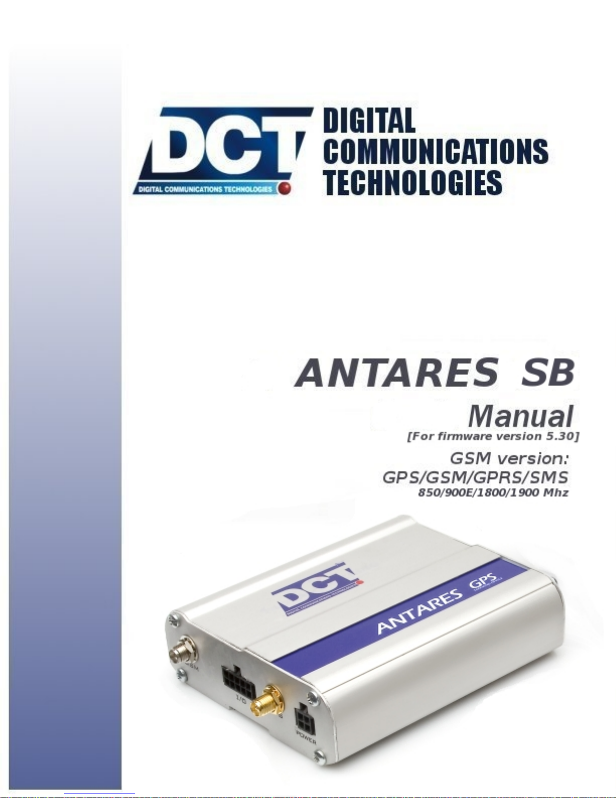
1.2 Contents of package
1.2. CONTENTS OF PACKAGE
Inside the Antares SBTMbox you will find the following content:
• An Antares SBTM.
• A GSM Quad-Band antenna ready to work with any GSM car-
rier regardless of its operation frequency.
• An active GPS antenna with magnetic support and reverse-
polarity connector.
• The I/O harness: 10 color-coded cables 1 meter (3.28 feet) long
attached to a female molex-type receptacle on the unit’s side
and open ends on the other.
• The Power harness: 3 color-coded cables 1 meter (3.28 feet)
long attached to a female molex-type receptacle on the unit’s
side and open ends on the other.
26
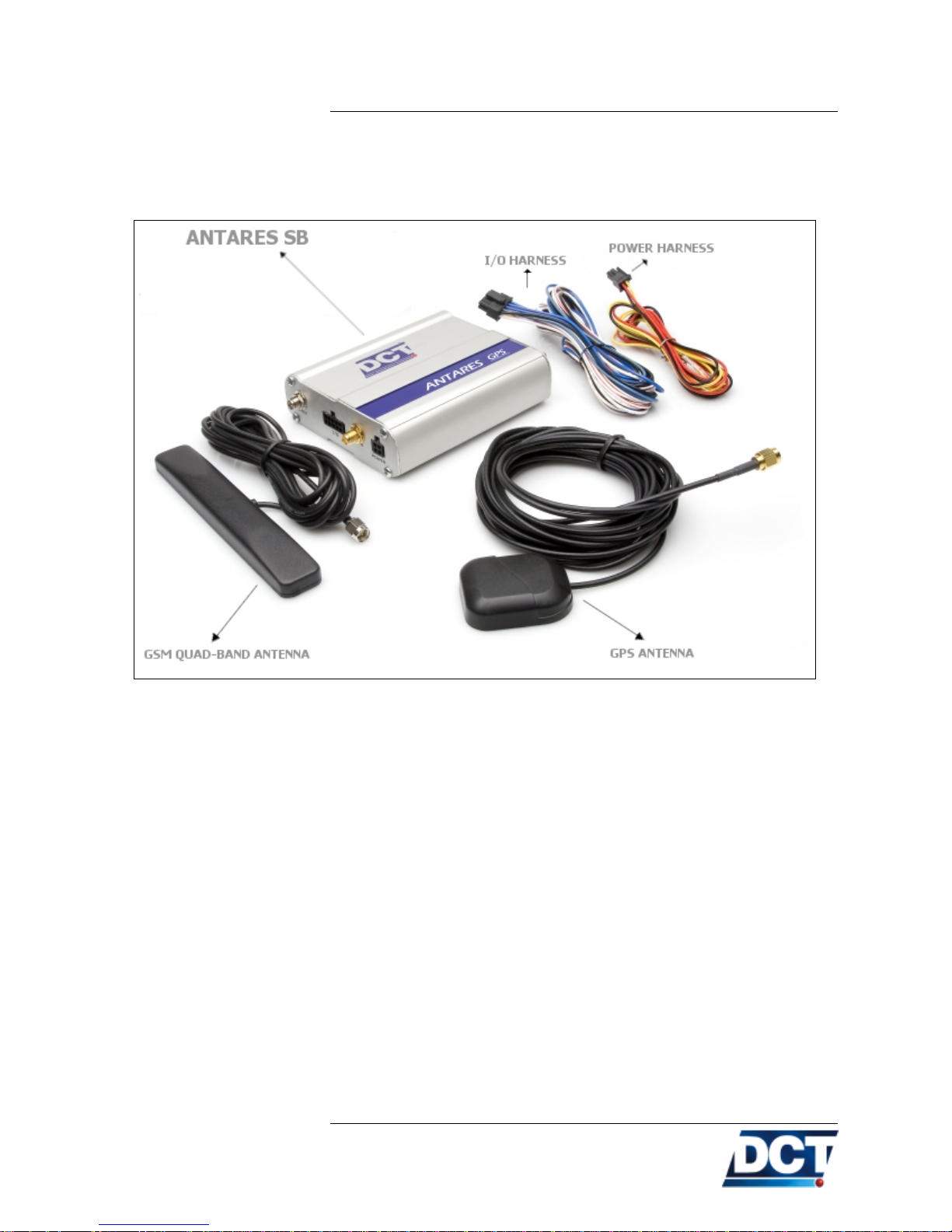
1.3. FRONT SIDE DESCRIPTION
1.3 Front side description
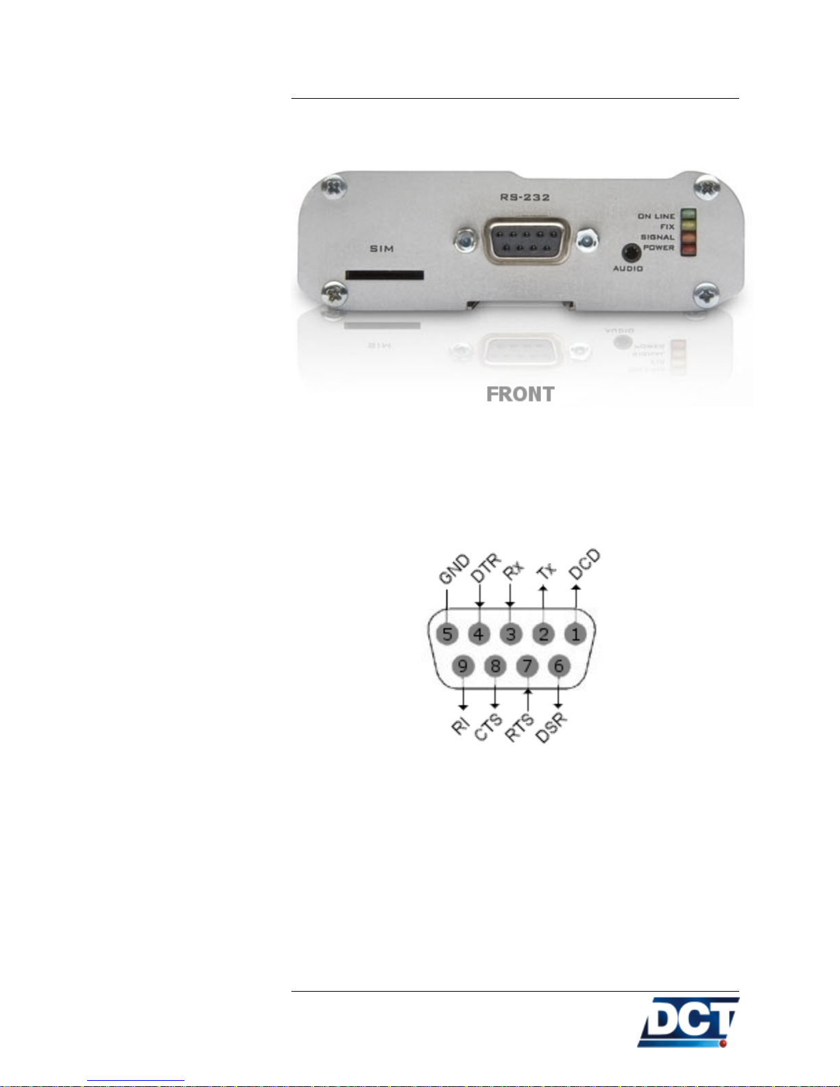
1.3.1 RS-232 port
DB9 female connector with all of the RS-232 signals available for serial communication.
The DB9 signals’ pin-out is:
Use this port to configure or query the unit and to connect accessories
like PDA-like devices or MDTs.
The Antares SBTM’s works as an RS-232 DCE device.
See the Serial Port section in the Operation chapter for more in-
formation.
27

1.3.2 SIM card slot
1.3. FRONT SIDE DESCRIPTION
Use this slot to insert the GSM SIM card. Insert the SIM card as
described on the next figure. Use a thin object like a coin to get the
SIM card fully inserted until it clicks.
1.3.3 LEDs
The SIM gets locked when it clicks. A click is only possible with the
correct orientation.
To remove the SIM card push it with a thin object until it clicks.
Four leds are provided:
• ON LINE: Green.
• FIX: Yellow.
• SIGNAL: Orange.
• POWER: Red.
See the LEDs section on the Operation chapter for more information.
28
 Loading...