

Page 1

[SU-27]
DCS
Eagle Dynamics
i
DCS: Su-27 Flanker
Flight Manu al
Page 2
DCS
[SU-27]
ii
DCS: Su-27 for DCS World
The Su-27, NATO codename Flanker, is one of the pillars of modern-day Russian combat aviation.
Built to counter the American F-15 Eagle, the Flanker is a twin-engine, supersonic, highly
manoeuvrable air superiority fighter. The Flanker is equally capable of engaging targets well beyond
visual range as it is in a dogfight given its amazing slow speed and high angle attack manoeuvrability.
Using its radar and stealthy infrared search and track system, the Flanker can employ a wide array of
radar and infrared guided missiles. The Flanker also includes a helmet-mounted sight that allows you
to simply look at a target to lock it up! In addition to its powerful air-to-air capabilities, the Flanker
can also be armed with bombs and unguided rockets to fulfil a secondary ground attack role.
Su-27 for DCS World focuses on ease of use without complicated cockpit interaction, significantly
reducing the learning curve. As such, Su-27 for DCS World features keyboard and joystick cockpit
commands with a focus on the most mission critical of cockpit systems.
General discussion forum: http://forums.eagle.ru
Page 3
[SU-27]
DCS
Eagle Dynamics
iii
Table of Contents
INTRODUCTION ........................................................................................................... VI
SU-27 HISTORY ............................................................................................................. 2
ADVANCED FRONTLINE FIGHTER PROGRAMME .......................................................................... 2
FROM T-10 TO T-10S.......................................................................................................... 9
TESTING........................................................................................................................... 12
41 RECORDS OF THE SU-27 ................................................................................................. 15
IN SERVICE ....................................................................................................................... 16
GENERAL DESIGN ........................................................................................................ 19
DESIGN ............................................................................................................................ 20
SYSTEMS AND AVIONICS ..................................................................................................... 22
COCKPIT .......................................................................................................................... 23
GAME AVIONICS MODE .............................................................................................. 26
NAVIGATION MODE ........................................................................................................... 28
AIR TO AIR MODE ............................................................................................................. 29
COCKPIT INSTRUMENTS .............................................................................................. 31
Airspeed and Mach Indicator ................................................................................................................... 32
Pressure Altimeter ................................................................................................................................... 32
Radar Altimeter ........................................................................................................................................ 33
Mechanical Devices Indicator .................................................................................................................. 33
AoA Indicator and Accelerometer ............................................................................................................ 34
Attitude Direction Indicator ..................................................................................................................... 34
Horizontal Situation Indicator .................................................................................................................. 35
Vertical Velocity Indicator ........................................................................................................................ 36
Aircraft Clock ............................................................................................................................................ 36
Tachometer .............................................................................................................................................. 37
Fuel Quantity Indicator ............................................................................................................................ 37
Interstage Turbine Temperature Indicators ............................................................................................. 38
Head Down Display (HDD)........................................................................................................................ 38
Radar Warning System ............................................................................................................................. 39
PPD-SP Panel ............................................................................................................................................ 42
Direct control switch ................................................................................................................................ 42
Trimming Mechanism .............................................................................................................................. 43
Automatic Control System (ACS) .............................................................................................................. 44
Page 4
DCS
[SU-27]
iv
SU-27 HUD AND HDD OPERATIONAL MODES ....................................................................... 47
Basic HUD symbols .................................................................................................................................... 47
Navigation Modes ..................................................................................................................................... 49
Beyond Visual Range Combat Modes ....................................................................................................... 50
Digital Datalink .......................................................................................................................................... 57
Work in Complicated Countermeasures Conditions ................................................................................. 58
Vertical Scanning - Close Combat Mode ................................................................................................... 60
BORE - Close Combat Mode ...................................................................................................................... 61
HELMET - Close Combat Mode ................................................................................................................. 61
Fi0 – Longitudinal Aiming Close Combat Mode......................................................................................... 62
Gun Employment ...................................................................................................................................... 63
Air-to-Ground Mode ................................................................................................................................. 65
Reticle ....................................................................................................................................................... 66
ELECTRONIC COUNTERMEASURES ......................................................................................... 68
Electronic Countermeasures (ECM) Stations of Su-27 .............................................................................. 68
SU-27 WEAPONS ......................................................................................................... 71
AIR-TO-AIR MISSILES ......................................................................................................... 71
SU-27 MISSILES ................................................................................................................ 73
R-27 (AA-10) Medium Range Missiles ....................................................................................................... 73
R-73 (AA-11) Short Range Missile ............................................................................................................. 76
AIR-TO SURFACE WEAPONS ................................................................................................ 80
Free-fall Bombs ......................................................................................................................................... 80
Unguided Aerial Rockets ........................................................................................................................... 84
RADIO COMMUNICATIONS AND MESSAGES ............................................................... 90
RADIO COMMANDS ........................................................................................................... 90
RADIO MESSAGES ............................................................................................................. 97
VOICE MESSAGES AND WARNINGS ..................................................................................... 100
THEORETICAL TRAINING ........................................................................................... 103
INDICATED AIR SPEED AND TRUE AIRSPEED .......................................................................... 103
VELOCITY VECTOR ........................................................................................................... 103
ANGLE-OF-ATTACK (AOA) INDICATOR ................................................................................. 103
TURN RATE AND RADIUS OF TURN ...................................................................................... 104
TURN RATE .................................................................................................................... 106
SUSTAINED AND INSTANTANEOUS TURNS ............................................................................. 107
Page 5
[SU-27]
DCS
Eagle Dynamics
v
ENERGY CONTROL ........................................................................................................... 108
SU-27 IMPLEMENTATION .......................................................................................... 109
FLIGHT CONTROL SYSTEM (FCS) ........................................................................................ 110
Longitudinal Channel ..............................................................................................................................110
Lateral Channel .......................................................................................................................................112
Directional Channel .................................................................................................................................115
NOZZLE CONTROL SYSTEM ................................................................................................ 117
SU-27 CHECK LISTS .................................................................................................... 119
Engine Ground Start ................................................................................................................................119
Engine Shutdown ....................................................................................................................................119
In Flight Engine Restart ...........................................................................................................................119
WEAPONS DELIVERY ........................................................................................................ 121
Beyond Visual Range Combat .................................................................................................................121
Close Air Combat .....................................................................................................................................124
Air-to-Ground Weapons ..........................................................................................................................129
SUPPLEMENTS .......................................................................................................... 132
ACRONYM LIST................................................................................................................ 132
Page 6
DCS
[SU-27]
vi
INTRODUCTION
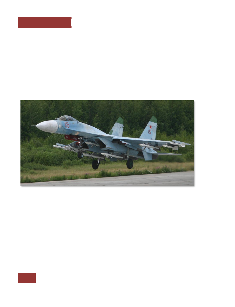
The Su-27, NATO codename Flanker, is one of the pillars of modern-day Russian combat aviation.
Built to counter the American F-15 Eagle, the Flanker is a twin-engine, supersonic, highly
manoeuvrable air superiority fighter. The Flanker is equally capable of engaging targets well beyond
visual range as it is in a dogfight given its amazing slow speed and high angle attack manoeuvrability.
Using its radar and stealthy infrared search and track system, the Flanker can employ a wide array of
radar and infrared guided missiles. The Flanker also includes a helmet-mounted sight that allows you
to simply look at a target to lock it up! In addition to its powerful air-to-air capabilities, the Flanker
can also be armed with bombs and unguided rockets to fulfil a secondary ground attack role.
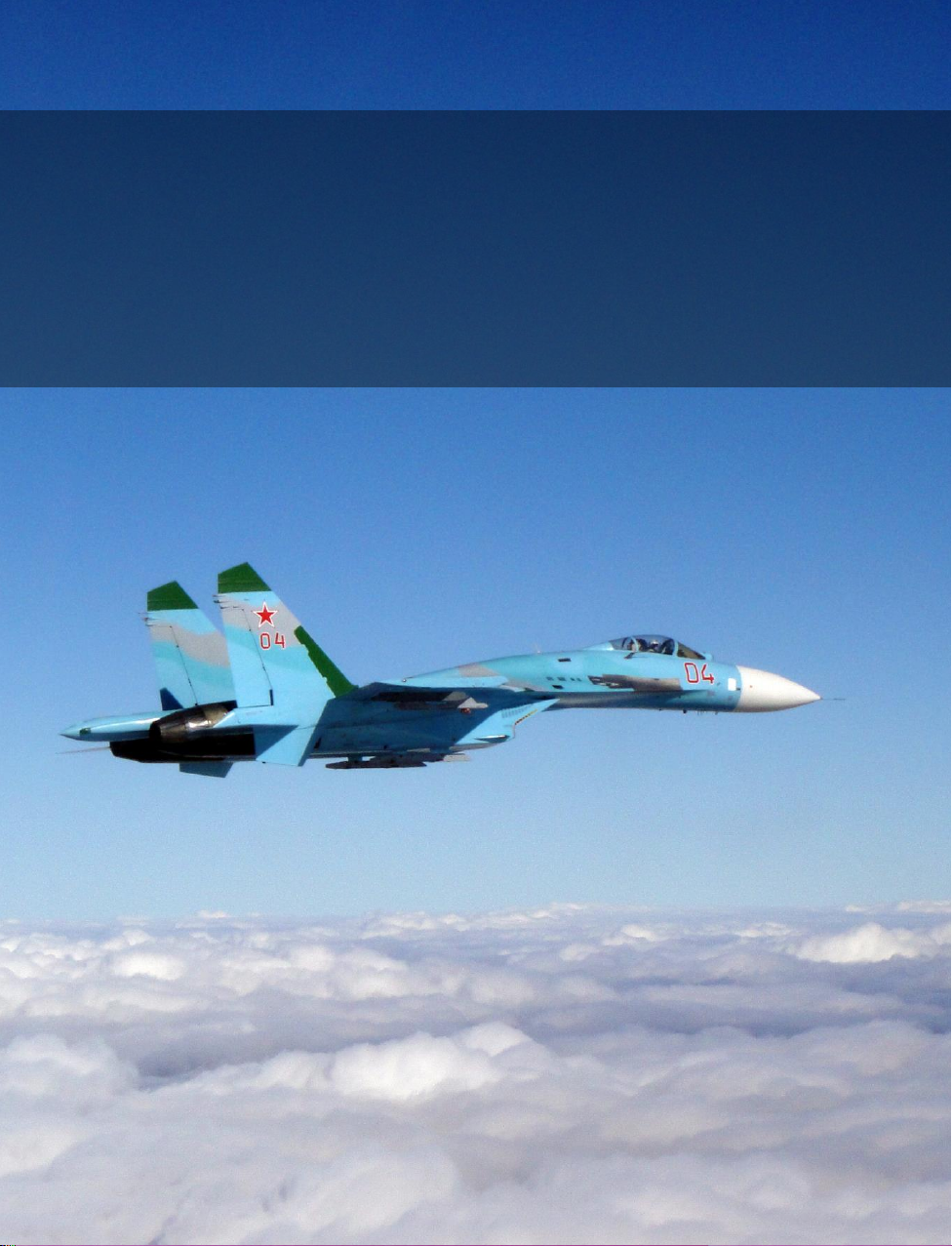
Figure 1: Su-27
Page 7
[SU-27]
DCS
Eagle Dynamics
1
Page 8
DCS
[SU-27]
2
SU-27 HISTORY
SU-27 HISTORY
The Su-27, a Russian fourth-generation single-seat supersonic fighter, is recognised all over the
globe as one of the best combat aircraft of the 20th century. Due to its perfect flight performances
and operational characteristics, the fighter is rightfully popular with pilots and technicians. Top
piloting capabilities of the Su-27 fighter demonstrated during multiple air shows around the world did
not leave anyone indifferent. The Su-27 is in the top lines of the aviation record tables of the
International Aircraft Federation. To the date, the Su-27 is a record-holder of 27 world class flight
achievements. The Su-27 is the forefather of a combat aircraft family of various functionality,
including the Su-27UB trainer, Su-33 ship-borne fighter, Su-30 twin-seat multirole fighter family, Su34 tactical bomber and deep modernized fighter Su-35.
To achieve such impressive results, the developers of the fighter had to follow the long and difficult
way. The creation of the fighter in its modern appearance with its current performances to guard the
Russian aerospace as well as that of the Su-27 buyers would not have been possible without
strenuous efforts made by many engineers, designers, scientists, researchers, pilots and military test
experts. The most significant input in the Su-27 development was made by teams of the Sukhoi
Design Bureau and Komsomolsk-on-Amur Aircraft Manufacturing Plant, developers of its powerplant,
radar and guided missile system from the Lyulka-Saturn Company, Tikhomirov Instrumentation
Research Institute and Vympel State-owned Design Bureau respectively. In addition to the above
organisations, the Su-27 fighter was being developed by many other scientific and research
institutions, including the TsAGI, CIAM, GosNIIAS, CNII, a range of other design bureaux and
research institutes that designed and manufactured various systems for the Su-27 fighter. This article
is dedicated to some aspects of the Su-27 development history which began 30 years ago.
Advanced Frontline Fighter Programme
A team of developers from the Kulon Machine-Building Plant headed by Pavel Osipovich Sukhoi
initiated in 1969 the development of an advanced new-generation fighter for the Soviet Air Force and
Air Defence Forces' aviation. By the mid-seventies, a general concept of the new fighter was
formulated in co-operation with a number of science and research institutions. This concept provided
for a high-manoeuvrability long-range fighter with a powerful weapons system and a perfect
sighting/navigation system that would allow the pilot to participate efficiently in both long-range
missile exchange and dogfight. The basic performances of the new fighter were to be of top class
globally while a number of characteristics was to exceed those of its American F-15 counterpart the
American leadership was reasonably vesting its high hopes in. The design bureau was planning to
introduce a number of major innovations and solutions into the design of the new fighter designated
T-10.
In 1970, the Sukhoi design bureau developed the first version of the fighter airframe incorporating
key features of the integrated aerodynamic configuration. The aircraft was to have a lifting body
featuring a smooth coupling of the wing and fuselage, two turbojet engines located in isolated bellymounted engine nacelles and two vertical stabilisers. Such an integrated design allowed a significant
improvement of the fighter's aerodynamics and provided for a more spacious interior to
accommodate fuel tanks and various equipment. For the fighter to achieve intended flight
performances within a wide range of altitudes and speeds, the new fighter's wing had ogyval shape
Page 9
[SU-27]
DCS
Eagle Dynamics
3
and a leading edge extension. According to the developers, the leading edge extension was supposed
to ensure required high-lift characteristics during the aerodynamic focus shifting at supersonic speeds
and generate vortice increasing wing, tail unit and control surface efficiency. At the same time,
Sukhoi was engaged in developing a traditional non-integrated version of the same fighter powered
by two adjacent engines, which were located in the fuselage's aft part, and fitted with side-mounted
air intakes and two vertical stabilisers. In 1972, both versions were submitted to the Air Force board
for examination and consideration. The board was to assess proposals submitted by three aircraft
design bureaux (Sukhoi, Mikoyan and Yakovlev) regarding development of an advanced tactical
fighter slated for entering the service with the Soviet Air Force in the early eighties.
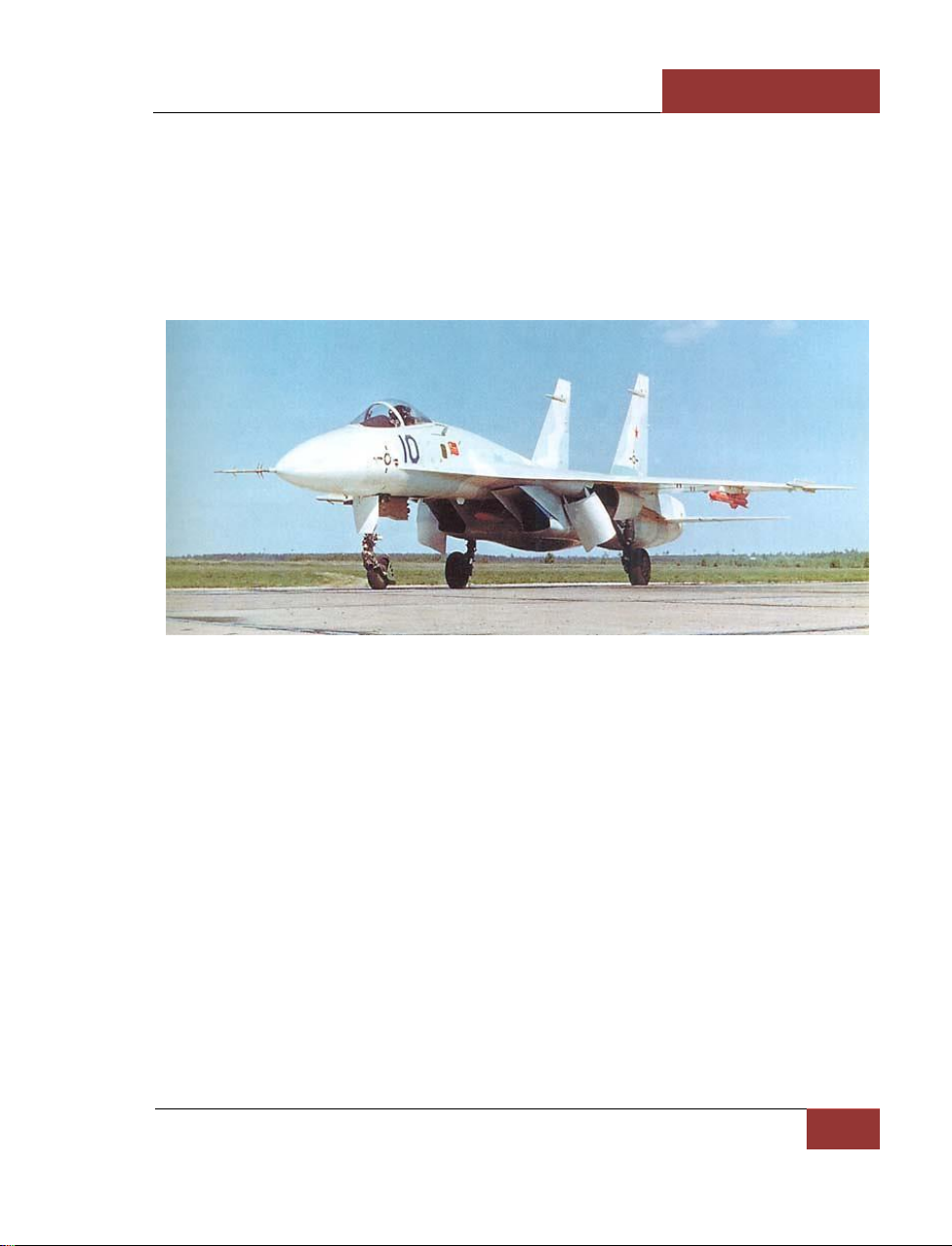
Figure 2: First prototype T-10-1
As a result of thorough evaluation and assessment of all versions submitted for consideration, the
proposals presented by Sukhoi and Mikoyan were approved by the board for further development.
The Su-27 (T-10) programme was to be developed into a heavy multirole advanced tactical fighter,
while the MiG-29 programme was to produce a series-built light advanced tactical fighter. Among the
major combat objectives the both fighters were to meet, there was the dogfight and medium-range
aerial combat capability, interception of aerial targets in the front and rear hemispheres both against
the sky and ground as well as the secondary task of ground target destruction. The Su-27, which had
a better fuel endurance, more weapons load and more sophisticated navigation, self-defence and
communication systems, was intended to operate independently within an air group deep behind the
enemy lines at an operational-tactical range of up to 250-300 km, while a lighter and cheaper MiG-29
would operate only at ranges of up to 100-150 km into the enemy-held territory. The Su-27's
weapons control system was expected to ensure successful countering the F-15 fighter, the most
capable fighter of that time available to the potential opponent, as well as successful engagement
when outnumbered by less capable but numerous fighters (for instance, YF-17, YF-16 and J-6).
Besides, the Su-27 fighter was intended for entering the service with the Soviet Air Defence Forces
after its appropriate reequipping and rearmament.
Page 10
DCS
[SU-27]
4
SU-27 HISTORY
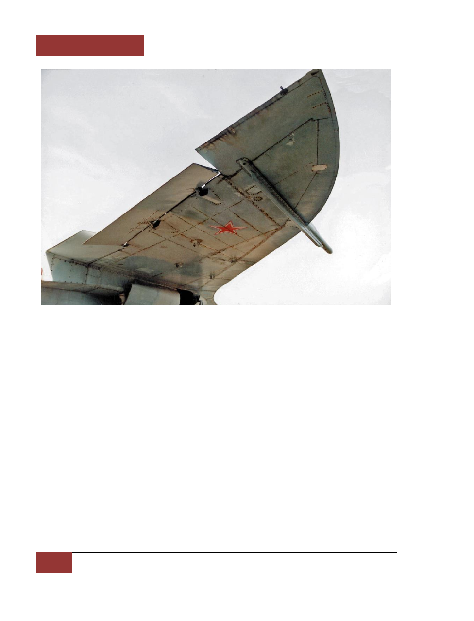
Figure 3: T-10-1 wing
Proceeding from the updated and more specific requirements the client set for the tactical fighter of
the eighties, Sukhoi started in 1972 developing a preliminary design of the T-10 fighter subsequently
followed by the conceptual design stage. During 1970-75, over 15 options of the fighter configuration
were given consideration. Those configurations varied not only in general approaches to the problem
(integrated or classic configuration) but differed in solutions suggested for individual problems
(engine and air intake positioning, landing gear design, type of the control system, etc.). Finally,
preferences were given to the aircraft design with an integrated statically unstable configuration. The
Su-27 was to become the first Soviet unstable fighter with longitudinal in-flight balancing to be
provided by a fly-by-wire control system. Accepting the longitudinal static instability concept (in other
words, "electronic stability") promised a lot of advantages: for the aircraft to balance at a high angle
of attack, the leading edge slat's upward deflection was required with its lift being added to the wing
lift, which allowed significant improvement of the fighter lift with a minor increase in its drag. Due to
the use of the integrated statically unstable configuration, the Su-27 was to acquire outstanding
manoeuvrability allowing the fighter altitude changes unavailable to typical configuration fighters and
an increase in its range of up to 4,000 km without external fuel tanks. There were no other seriesproduced fighter in the world boasting similar performances.
The fighter's aerodynamic configuration featured a regular scheme with the empennage being
situated behind the wings on the load-carrying beams on the outer sides of the separated engine
nacelles. The aircraft had twin tails mounted on the engine nacelles. The plane was to be controlled
by the all-moving horizontal stabiliser whose panels could deflect in different directions, as well as by
Page 11

[SU-27]
DCS
Eagle Dynamics
5
ailerons and rudders. The wing high lift devices included flaps. To enable the powerplant to produce
the optimal performances at any speed and altitude, the air intakes mounted under the centrewing
were made controllable by the horizontal ramp. The fore part of the fuselage housed an integral
radar covered by a radio transparent nosecone as well as the cockpit featuring a canopy that
provided good visibility in all directions.
Figure 4: T-10-3
The Su-27 fighter weaponry which included 30 mm high-rate cannon, K-27 medium-range air-to-air
missiles and K-73 or K-14 short-range missiles was to be standardised with that of the MiG-29 light
tactical fighter. The only difference in armament was the warload carried: while the MiG-29 could
house only six missiles, including two K-27 missiles, the Su-27 was capable of carrying eight,
including four K-27s, as well as the K-27E improved longer-range radar-homing and heat-seeking
missiles.
An integrated weaponry control system of both fighters was substantially standardised and, for the
first time in the history of aviation, included two complementing channels - a radar sighting system
and an optoelectronic sighting system, as well as a helmet-mounted sight. The sighting system
initially designed for the Su-27 fighter had better characteristics. The N001 radar was built by the
Phazotron Research and Development Association under the guidance of Victor Grishin. The OLS-27
optics-based detection and ranging system combining an acquisition/tracking IR locator and a laser
rangefinder was developed by the Moscow-based Geophysics Central Design Bureau headed by Chief
Designer D.Khorol.
The landing gear featured a classical tricycle design with the nose strut having been moved far
forward and the gear well placed under the cockpit. The main gear struts were made forwardretractable into centrewing gear wells with the wheels being turned in the process and the wells'
forward doors serving as air brakes.
The Su-27 fighter powerplant included two powerful and economical AL-31F bypass turbofan engines
producing thrust of 12,500 kg each. They were developed by the Saturn Mechanical Plant headed by
Arkhip Mikhailovich Lyulka and supposed to ensure take-off thrust-to-weight ratio exceeding 1. Low
specific fuel consumption along with about eight tonnes of fuel stored in internal tanks filling most of
the airframe inner space was to ensure required operational range of the fighter.
Page 12

DCS
[SU-27]
6
SU-27 HISTORY
Figure 5: T-10-1 in the Russian Air Force Museum (Monino)
The Su-27 fighter conceptual and detailed design stages were completed in 1975-1976, and after
issuance of required design documentation and drawings, the manufacturing of first prototypes was
initiated at the Kulon plant. Unfortunately, Pavel Sukhoi did not live long enough to see the fighter he died in 1975 to be succeeded by Yevgeny Ivanov. From 1976 on, the Su-27 programme has been
under immedeate guidance of Chief Designer Mikhail Simonov. The first prototype designated T10-1
was completed in early 1977. Due to the lack of the Al-31F turbofan bypass engines, the prototype
was equipped with two AL-21F-3AI engines - a modified version of the series-production AL-21F-3A
engine mounted on other Sukhoi-developed fighters (Su-17, Su-24). After the completion of required
ground checks and run-ups, everything was ready for test flights and on 20 May, 1977 Vladimir
Ilyushin, Sukhoi's chief pilot, took the T10-1 off the ground for its maiden flight. The first prototype
was used to evaluate its key flight performances as well as stability and controllability.
In 1978, the second prototype designated T10-2 was completed though its life was brief. On 7 July,
1978, the fighter suffered a mid-air accident resulting in death of test pilot Yevgeny Solovyov. The
crash was triggered by the plane's oscillation in the longitudinal plane at a supersonic speed, due to
which it suffered an extremely high g-load and disintegrated in midair. The black box recorder
readings showed that the fighter got into an unexplored resonant mode, which caused the mid-air
disintegration of the aircraft. This happened so fast that Yevgeny Solovyov, distinguished test pilot
and Hero of the Soviet Union, had no chance to eject. The after-action review established the actual
reasons for the tragedy and allowed the developer to introduce necessary changes into the fighter's
design. During 1978, preparations for preliminary production of the Su-27 were made at the Gagarin
machine-building plant situated in the Far Eastern city of Komsomolsk-on-Amur. At the same time,
the Sukhoi mechanical plant commenced assembling another two Su-27 prototypes. Unlike the first
two prototypes, those two fighters were to be powered by AL-31F engines. The new powerplant was
500 kg lighter, its thrust was 12 percent higher than that of the predecessor with fuel consumption
being lower. In comparison with the AL-21F-3s, the AL-31F engines had smaller diameter and length
while their nozzles were accommodated with a secondary (bypass) duct control system. On 23
August, 1979, Vladimir Ilyushin took the T10-3 off for its maiden flight. Two months later, the T10-4
joined the flight testing too. At first, both aircraft were used for in-flight engine testing. Then the
Page 13
[SU-27]
DCS
Eagle Dynamics
7
T10-3 was remodeled to be further tested on the Nitka training facility in support of the development
of the Su-27 ship-borne version while the T10-4 was used for the further refining of the weapons
control system.
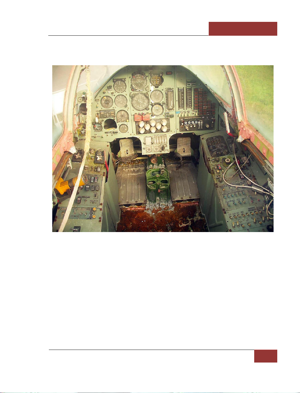
Figure 6: T-10 cockpit
By the early 1980, as many as three prototypes (T10-1, T10-3 and T10-4) had been taking part in
the Su-27 testing programme with first pre-series aircraft expected to join soon. It seemed that
everything was in line with the schedule and the new fighter would have been fielded in a couple of
years. However, there were staunch objections against commencing series production of the aircraft
in the then airframe configuration, made by the Siberian aviation research institute's (SibNIA)
aerodynamic experts and... Chief Designer Mikhail Simonov himself. According to the SibNIA experts
who had done the bulk of aerodynamic research under the Su-27 programme, several mistakes were
made during the fighter development stage. The combination of the accepted wing planform and
leading-edge extension configuration caused premature vortex flow separation: the non-stationary
airflow around the wing would begin as early as at the 8-to-10 angle of attack (AoA), which would
cause deterioration of the airframe's lifting capability, buffeting and decrease in lateral stability. The
tail unit configuration designed for the T10 would fail to provide required effectiveness of the
longitudinal control surfaces, lateral and directional stability devices. The SibNIA-held T-10 wind
Page 14
DCS
[SU-27]
8
SU-27 HISTORY
tunnel tests performed in 1975-76 indicated that there was a slim chance of developing a highly
manoeuvrable fighter without dealing first with the above problems.
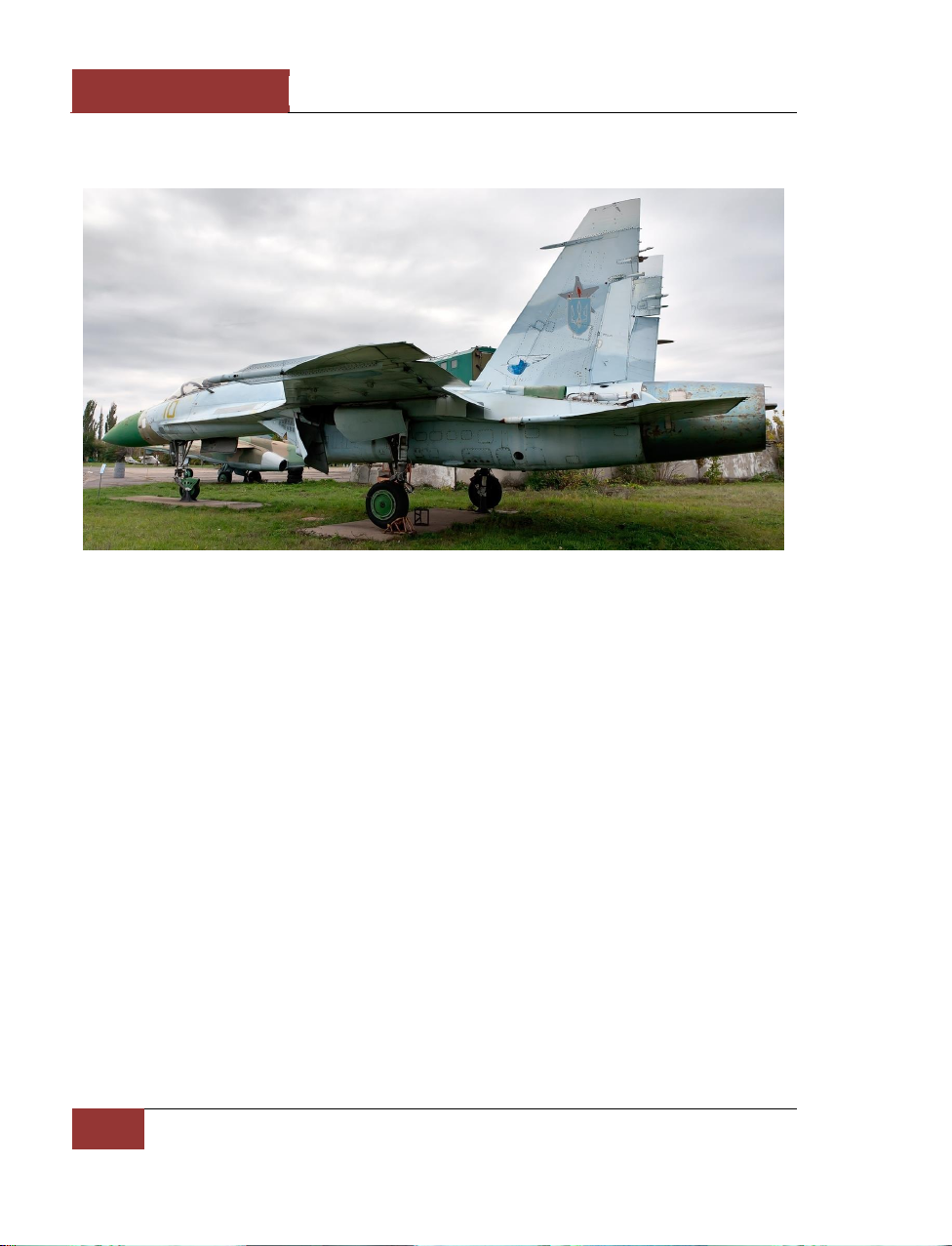
Figure 7: T-10-10 at museum, Lugansk, Ukraine
The necessity of the Su-27 programme's radical reconsideration was looming ahead. Such
fundamental elements of the fighter design as the form and area of the wing, leading-edge extension
configuration, horizontal and vertical control surface arrangement were have to be redesigned.
Mikhail Simonov was a staunch supporter of such an approach but the Aviation Industry Ministry's
brass had a different opinion. Designer Ye.A.Ivanov was not too keen on taking risk by radically
revamping the design. As a result, first Su-27s were tested in their initial configuration. The flight
tests of the T10-1 and T10-3 corroborated to the Siberian aerodynamics experts' doubts. To make up
for the vertical stabiliser effectiveness decrease resulting in a decrease in the fighter's directional
stability at a high AoA, first planes were fitted on the TsAGI advice with top-of-the-wing-mounted
fences. However, the fences reduced the airframe's lifting capacity and negated the advantage of
using the leading edge extension roots.
The T-10 testing also revealed the failure of the fighter's certain characteristics to match those of the
performance specifications. First of all, that was true for the range: the mismatch between the
required and actual ranges exceeded 20 percent. The Designer General reported to the ministry that
there were two main reasons for non-compliance with certain requirements set in the performance
specifications. Firstly, avionics developers failed to meet the weight limits set out in the avionics
performance specifications. The summary avionics excessive weight comprised a few hundred
kilograms, which, naturally, led to the aircraft's overall weight increase, hampered its manoeuvrability
and reduced its range. Secondly, the engine's specific fuel consumption ordered in the performance
specifications had not been achieved by the developer either. Truth be told, the issue was settled
later when the requirements to the engine's specific fuel consumption were found to be a tall order
which could not be met then. In spite of the T-10's considerable deficiencies revealed during the
research and flight tests, Yevgeny Ivanov hoped, nonetheless, for possibility to gradually hone that
Page 15

[SU-27]
DCS
Eagle Dynamics
9
configuration through minor design modifications, fuel capacity increase, etc. Otherwise, Mikhail
Simonov was pushing hard for radical aircraft reworking, since as early as in 1976-77 a team of his
subordinates in cooperation with the SibNIA scientists developed on their own and later tested in the
wind tunnel a new configuration of the airframe devoid of the deficiencies which the previous
configuration had in abundance. Justice should be done to M.P.Simonov (who went to work for the
Aviation Industry Ministry in 1979 to return to Sukhoi as Designer General in 1983) who managed to
persuade the leadership to risk radical change in the configuration of the fighter that had been
already undergoing tests by then. With the passage of time, this decision proved to be right and led
no matter what to building the aircraft that still - almost two decades later - has been regarded as
one of the best warplanes in the world. Having commenced production of the Su-27 in its final
configuration, Sukhoi confirmed its reputation of a world leader of aviation industry in line with its old
tradition of never fielding mediocre aircraft.
From T-10 to T-10S
The fighter's version featuring the new configuration was designated T-10S by the Sukhoi design
bureau with its full-scale design work starting in 1979. Preliminary attempts to deal with the first T-10
version's glitches and meet the performance specifications' requirements, made by the design bureau
and SibNIA (in the SibNIA the work was headed by Stanislav Kashafutdinov, candidate of technical
sciences) resulted in setting the guidelines for modifying the initial configuration. With the developing
of those guidelines, differences in design between the T-10S and T-10 became even more obvious.
In the end, it became clear that the designers would have to develop an utterly different aircraft.
According to Mikhail Simonov, the only things the T-10S inherited from its T-10 predecessor were the
main landing gear's wheels and ejection seat. Only general principles set up for the Su-27 by
P.O.Sukhoi himself, such as the integrated airframe configuration, statically unstable design with the
aft centre of gravity, fly-by-wire control system, mounting the engines in isolated engine nacelles
with belly-mounted air intakes, etc., were retained.
Figure 8: T-10-21 (T-10S) mockup in the air tunnel (SibNIA)
Page 16

DCS
[SU-27]
10
SU-27 HISTORY
The T-10S had a new wing featuring a straight leading edge, an aerodynamic twist and a
reconfigured sharp leading edge extension. Ogyval wing tips lost the ground to traditional permanent
leading edge sweepback angle ones featuring pylons for air-to-air missiles, which resulted, firstly, in
discarding flutter-preventing weights carried by the T-10 and, secondly, in beefing up the number of
missiles from eight to 10. The wing area grew from 59.4 sq.m to 62 sq.m with the wing high-lift
devices being changed drastically. Ailerons and flaps were replaced with unified control devices flaperons, wing leading edges were fitted with slats (the T-10 had no leading edge high-lift devices),
the automatic adaptive deflection mode for the flaperons and leading edge slats was ensured
providing for the fighter's "polar curve envelope" flight concept. The airframe's lifting characteristics
were enhanced through the use of the new wings and leading-edge extensions while maintaining the
negative pitching moment at positive angles of attack and extending significantly the range of
operational angles of attack, which ensured satisfactory lateral stability and prevents buffeting.
Figure 9: T-10 evolution
To reduce drag, the fore part of the airframe was reworked: the airframe cross section in front of and
around the cockpit was decreased, canopy's midsection was reduced while its rearward movement
was enhanced, the airframe's fore part cross section in the area of first fuel tanks was increased.
Besides, airframe and spine fairing couplings were introduced along its whole length, spine fairing's
lateral cross section in the airframe's midsection was reduced, central tail boom arrangement was
altered through addition of a cylindrical tip which was an extension of the rear integral tank. At the
same time, the total internal fuel capacity increased making up 9.4 tonnes. Making the shape of the
engine nacelles more graceful while reducing their weight was achieved through fitting the T-10
aircraft with AL-31F engines featuring top-mounted aircraft and engine accessory gearbox (the T10-3
Page 17
[SU-27]
DCS
Eagle Dynamics
11
and T-10-4 were powered by the AL-31F engines featuring bottom-mounted accessory gearboxes).
While preserving the general arrangement of air intakes, the new aircraft had a new foreign-object
damage (FOD) system introduced for preventing FOD during taxiing, run and take-off through the
use of extendable screens in the air intakes' ducts. Supplementary air inlet ramps were added to the
lower surface of the air intakes.
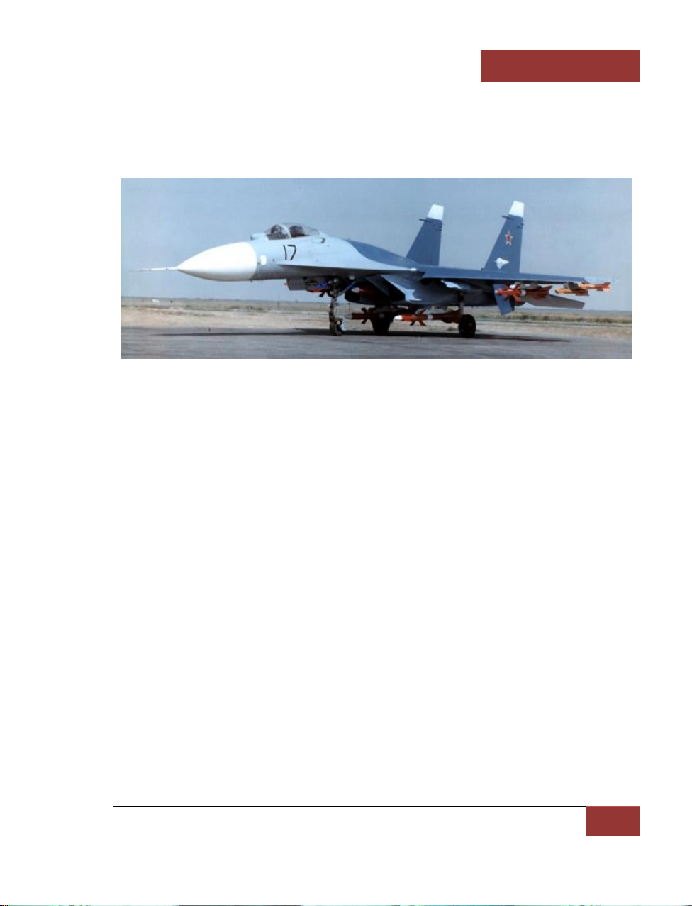
Figure 10: T-10-17 with 10 missiles
To enhance directional and lateral stability through raising efficiency of the corresponding control
surfaces, the empennage underwent substantial redesigning. The two vertical stabilisers were set
wide apart at the reinforced booms on both sides of the engine nacelles with an optimum position for
the stabilisers chosen in the vortex system generated by the leading edge extensions and wing
panels. This resulted in considerable increase in directional stability and controllability of the fighter
at high angles of attack and slipping. Also, the T-10S was fitted with ventral fins increasing its
directional stability and anti-spin performances. Mounting the tails on the tail beams provided an
increase in the tails' and horizontal stabiliser area, as well as to place the stabiliser's actuator fairings
behind the tails. The planeform of the empennage was altered too, while the change in the position
of stabiliser panel rotation semiaxes enhanced their flutter characteristics and allowed the designers
to discard the anti-flutter loads mounted on the T-10. The air brakes - the main landing gear doors
featured by the earlier version and discarded due to horizontal control surface flutter caused by their
extending - were ousted by the large air brake mounted behind the cockpit.
The landing gear was reworked too: main struts were provided with "slant" main pivot, which made it
possible to retract the gear into the wing centre section, thus requiring no folding struts to be
installed. This also allowed to reduce the lifting body's cross section in the area of the landing gear
wells. The nose gear strut was reinforced and moved aft, which enabled better taxiing and decreased
a chance of foreign object damage during taxiing, run and take-off. In general, the fighter's
configuration modification provided the lifting body midsection reduction by 15 percent, which led to
reduction of drag by 18-20 percent in the subsonic and supersonic speed range. This, combined with
an increase in the airframe's lifting characteristics as well as lateral and directional stability and
controllability in all three planes in every flight mode, provided the aircraft with superior
manoeuvrability with special emphasis put on high angles of attack and met the requirements set for
the fighter's range.
Page 18

DCS
[SU-27]
12
SU-27 HISTORY
Testing
In 1980, when the new-version prototype assembly was in full swing at Sukhoi, the pre-production
batch assembly was nearing the end at the series production plant in Komsomolsk-on-Amur. As far as
their design was concerned, they were the deadringers for the T10-1 and T-10-2 prototypes with only
difference being their canted tails resembling those of the T10-3 prototype. Their powerplant still
retained the AL-21F-3AI engines. Despite the fact that the planes had little in common with the
future series-made Su-27, it was decided against cancellation of the pre-production batch. The
decision was made to use them for honing the weapons control system and other equipment as long
as first T-10S were being manufactured and put through initial stages of the testing programme. This
was intended to make up for inevitable dragging behind the schedule due to the need of reequipping
the production lines for manufacturing the new-configuration aircraft. The first aircraft of the preproduction batch designated T10-5 was finished in July 1980 and followed in the same year by the
T10-6 and T10-9 (numbers 7 and 8 were assigned to first T-10Ss). In 1981, the Komsomolsk-based
plant produced another two fighters - the T10-10 and T10-11, thus making five flying prototypes of
the pre-series batch aircraft designated Su-27, Type T10-5 to discern them from future series-built
aircraft. By 1982, there have been produced nine initial-configuration aircraft and one for static tests
including those assembled at the Sukhoi plant.
Sukhoi completed the assembly of the first T-10S prototype designated T10-7 (a.k.a T10S-1) in early
1981 and in April 1981 it made its maiden flight piloted by test pilot V.S. Ilyushin. Also in 1981, the
static version (T10-8, or T10S-0) and the second flying prototype featuring new configuration were
built. From 1981 on, the Su-27 programme has been headed by Alexei Knyshev who has been the
aircraft's Chief Designer ever since. The T10-7 and T10-12 were used to determine main
performances of the new-configuration fighter, its stability and controllability, as well as to evaluate
the new powerplant featuring top-mounted accessory gearboxes. However, both aircraft were not
destined to fly long. On 3 September, 1981, the T-10-7 was lost due to a fuel system malfunction.
Vladimir Ilyushin had to punch out while the fighter with its tanks nearly empty hit the ground in a
fireball. On 23 December, 1981, the T10-12 crashed too due to entering uncontrolled spin while
performing deceleration from the max speed. The fore part of the air frame was destroyed resulting
in the aircraft hitting the ground. The test pilot, Aleksandr Komarov, died in the crash.
It proved to be impossible to determine all reasons for the crash. However, in 1983, Sukhoi's test
pilot Nikolai Sadovnikov found himself in a similar situation while flying one of the first seriesproduced Su-27s - the T10-17. During the low-altitude high-speed level flight, Sadovnikov's fighter
suffered destruction of a leading edge slat and part of the wing panel with the debris damaging
vertical stabilisers. Thanks only to the high skills of the pilot (who was later awarded the title of Hero
of the Soviet Union and set quite a few world records), the sortie did not end up in a crash. Nikolai
Sadovnokov landed the damaged fighter with most of the wing panel missing and a tail clipped, thus
providing the developers with precious information to rake their brains over. It was found out later
that the
reason was a mistake in the calculation of the hinge moment emerging due to the deflection of the
adaptive leading edge flap in certain flight modes. Urgent measures were taken to rework the design,
including the reinforcement of the airframe and wings as well as the development of lesser-area
adaptive leading edge slats.
Page 19
[SU-27]
DCS
Eagle Dynamics
13
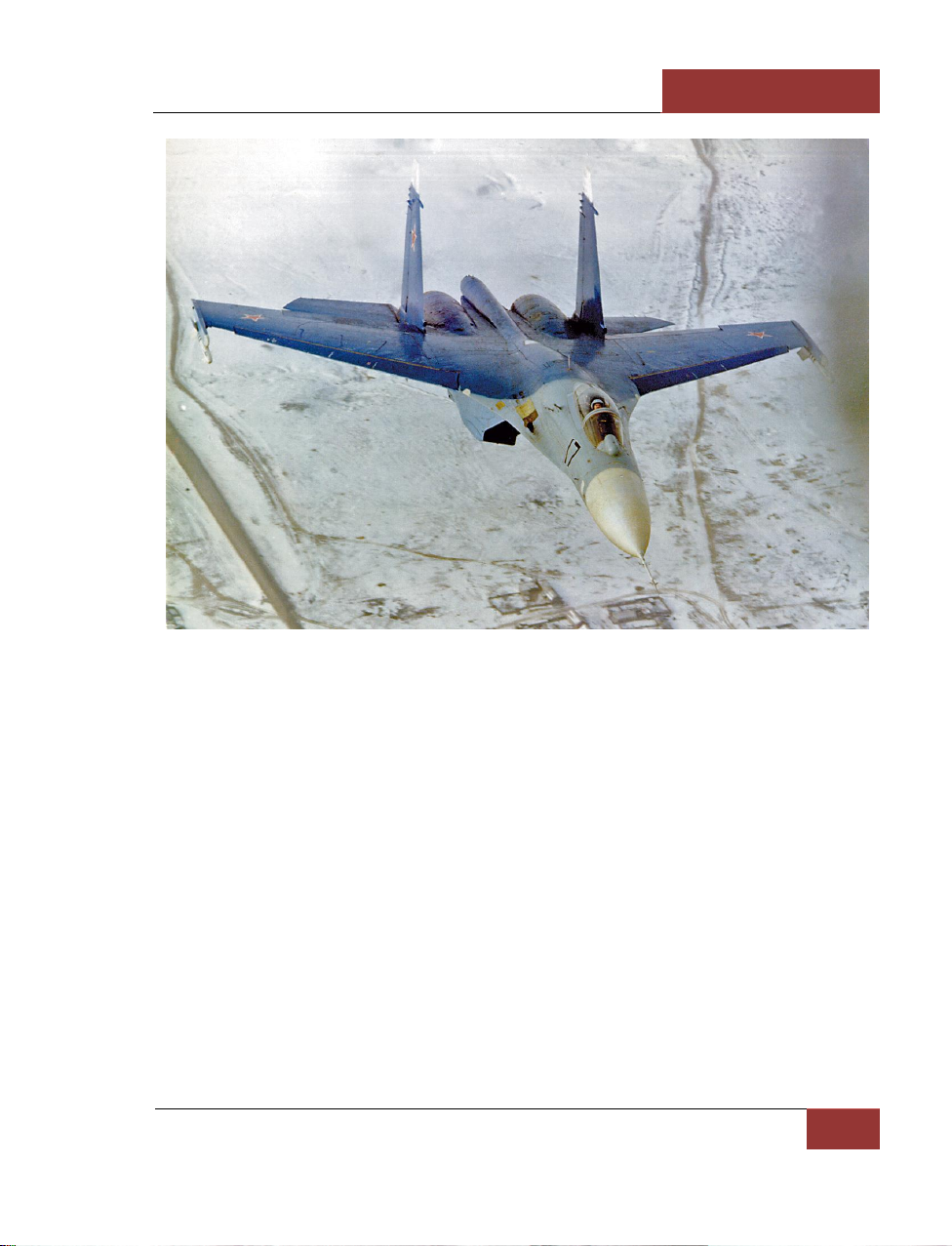
Figure 11: T-10-17 in a test activity
In 1982, the new fighter's testing programme was joined by first new-configuration aircraft
manufactured in Komsomolsk-on-Amur, namely: the T10-15 (later converted into the P-42 recordmaker), T10-16 and above-mentioned T10-17. The fly-out of the first series-built Su-27 took place on
2 June, 1982. The next year, Komsomolsk-based plant delivered another nine fighters, namely, T1018, T10-20, T10-21, T10-22, T10-23, T10-24, T10-25, T10-26 and T10-27, most of which were used
in the Su-27 joint official testing held in parallel with establishing series production of the new aircraft
and its fielding with line units. The work on the T10-5 pre-series batch being in full swing too. The
testing resulted in the substantial reworking of the fighter design. Thus, the fore part of the airframe
and the wings were reinforced with the existing fighters being outfitted with additional external
reinforcing plates and those under construction being given reinforced primary structural members
and skin panels. The shape of the tail tips was altered too with previously-designed tail-mounted
weights being discarded. The hinged part of the canopy was made to move up and rearwards (while
earlier it was rear-sliding) with an additional behind-the-headrest metal casement being incorporated
into it. To house the chaff dispenser, the length and height of the flipper - a rear-fuselage bay
between the centre bean and engine nacelles - were increased. The wingtips were modified to carry
ECM pods instead of air-to-air missile launching rails.
In 1984, first Su-27s were fielded with the Soviet Air Force followed by almost a hundred more
fighters having been produced by the end of the next year as well as by Air Force and Air Defence
Forces' units mass transition to the new fighter. The Su-27 joint official testing was completed in the
Page 20
DCS
[SU-27]
14
SU-27 HISTORY
mid-80s. Its results testified to the fact that a really outstanding aircraft had been made, which was
second to none among the fighters as far as its manoeuvrability, range and combat effectiveness
were concerned. However, certain avionics components required the additional testing held under
special programmes after the joint official testing was over. With the avionics problems resolved, in
1990 the Su-27 was officially adopted in the inventory of the Soviet Air Force and Air Defence Forces
aviation.
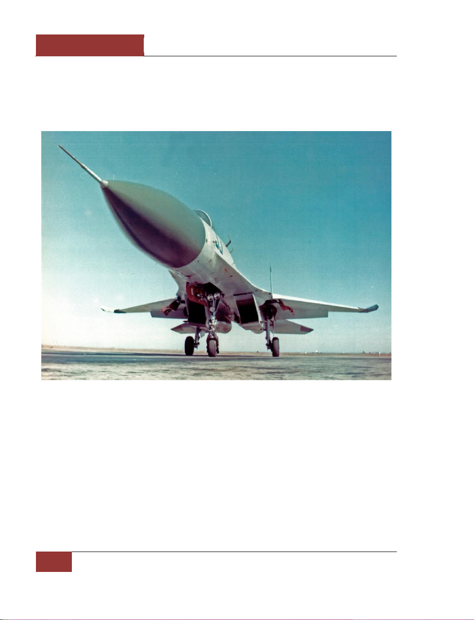
Figure 12: T-10-33
Due to the fact that the Su-27 differed considerably from the rest of Soviet fighters both in
performances and weapons control system, navigation suite and other equipment, its twin-seat
combat trainer version designated Su-27UB had to be designed. It was supposed that retaining the
full avionics and weapons suites inherited from the combat version would enable the twin-seater to
be used as an effective combat aircraft. Moreover, considering the Su-27's range and fuel endurance,
the crew of two was supposed at times to be a better option.
The Sukhoi team had begun designing the Su-27UB (developer's designation T-10U) in the late
seventies even before the testing of first new-configuration aircraft commenced. The developer was
tasked with providing a high degree of unification of the single-seater and twin-seater's avionics
design with the fighter retaining its superior performances. In 1980, the predesign work was
completed. The Su-27UB's aerodynamic configuration mainly matched that of the single-seater. The
primary differences lay in the design of the airframe fore part which incorporated a two-seat tandem
Page 21
[SU-27]
DCS
Eagle Dynamics
15
cockpit, as well as in the design of the tails whose area had to be increased to preserve directional
stability. To provide good visibility from the back seat, the rear part of the cockpit was elevated a
little in relation to the forward part with both cockpit parts having been equipped with a single upand-backwards opening hinged part of the canopy to ensure the ease of operation and ejection
safety. Placing the backseat crew member higher than the pilot required changing the fuselage spine
fairing shape above the forward fuel tank and centrewing with the aircraft acquiring a hunchback
appearance. However, this allowed the plane to retain the design and configuration of the nose
wheel and its well with two lateral avionics bays having been placed under the rear cockpit. This also
prevented the reducing of the fuel capacity and extending the fuselage length. Each tail of the twinseater comprised a single-seater tail panel and a 420 mm spacer that increased the area by 1.55
sq.m.
41 records of the Su-27
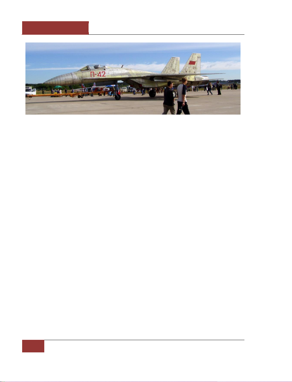
Late in 1986, the press reported new rate of climb records established by the new Soviet jet - P-42.
On 27 October, 1986, pilot V.G.Pugachov climbed to an altitude of 3,000 m in 25.4 seconds while on
15 November he climbed to 6,000, 9,000 and 12,000 m in 37.1, 47.0 and 58.1 sec respectively, thus
exceeding by over 2 sec the decade-long records set by American pilot R.Smith flying the F-15. The
records were set in two classes simultaneously - both in the class of jet aircraft and in that of 12-16 t
service aircraft. The latter raised quite a few brows among experts who realised fast enough that the
P-42 designation was applied to the new fighter - the Su-27. The point is the 20 t fighter could hardly
fit the 16 t aircraft class, and, as was revealed later, the IAF protocols had the P-42's take-off weight
at 14,100 kg, which is as much as two tonnes lighter than an empty Su-27. This was simple enough:
to set records, Sukhoi's leadership took a decision to use one of the first series-built Su-27s - the
T10-15 that by then had completed its testing programme. According to Designer General
M.P.Simonov, the aircraft's unusual designation was used due to the following reason: "it was
designated P-42 to commemorate the turning point of the Stalingrad battle in November 1942. Then,
the Soviet aviation's role in defending that stronghold was crucial." The plane was stripped of the
weapons control system and radar to make it fit the weight constraints. Besides, it had the central tail
boom shortened, tail area reduced, drag chute and fences removed, wing high lift devices keyed,
radar nosecone was replaced with a lighter metal one. Some other measures to reduce weight were
taken too. To perform the record flights, the aircraft had only a limited amount of fuel in the tanks,
that was enough only for take-off, achieving the goals and landing. The designers managed to soup
up the engines with each having its thrust increased by over 1,000 kg/f (the R-32 engines and the
thrust of 13,600 kg/f were included into IAF protocols ). The measures taken allowed the designers
to achieve a unique take-off thrust-to-weight ration totalling nearly 2. Due to this, the P-42 was
capable of accelerating and even crossing the sonic barrier during the vertical climb.
Page 22
DCS
[SU-27]
16
SU-27 HISTORY
Figure 13: P-42 record plane
However, the aircraft's great thrust-to-weight ratio evoked a very peculiar problem: the P-42's brakes
were unable to hold it at the starting position when the engines went in afterburner. So, a rather
ingenious solution was made: the plane was linked up with a towrope and a special lock to a
powerful tractor protected from the exhausts with an armoured plate. The tractor would go to the
runway and keep the aircraft from the premature run by its impressive weight. At a predetermined
moment, the lock would separate the towrope from the plane, the cameras and stopwatches would
be switched on and the P-42 would rush to set new world records. The work on the P-42 record
preparation was headed by leading engineer (later - Chief Designer) R.G.Martirosov. On 10 March,
1987, the P-42 flown by N.F.Sadovnikov exceeded its own 9 and 12 km climb records by another
three seconds - 44.2 sec and 55.5 sec respectively. On the next day, the aircraft was used in the
STOL class. The rate of climb to an altitude of 3, 12 and 15 km was 25.4, 57.4 and 75.7 sec
respectively. On 10 June, 1987, the P-42 flying as a STOL-class aircraft set a record for the level
flight altitude that amounted to 19,335 m. The last of the official records set by V.G.Pugachov while
flying the P-42 was a climb to 15,000 m in 81.7 sec with a weight of 1 tonne. All in all, the aircraft
had established 27 world records during 1986-1988 with world record-holder diplomas having been
issued to V.G.Pugachov, N.F.Sadovnikov, O.G.Tsoy and Ye.I.Frolov.
In Service
The deliveries of Su-27 fighters to the combat units began in 1984. When under development, a
decision was taken that the aircraft of the class would be operational in fighter air regiments of two
types - in Air Force and Air Defence Forces' units. In so doing, the Air Force tactical aviation and ADF
fighter units were supposed to have in service virtually the same aircraft, with the development of
specialised RusAF and ADF versions not envisaged. It is noteworthy that earlier the Russian fighters
had only one 'master' as a rule, with the MiG-21 operated exclusively by Air Force units and the Su-9,
Su-11, Su-15, Tu-128, and MiG-25P by the ADF. The only aircraft, which used to be operated by both
the Air Force and Air Defence, is the MiG-23. And still, there was a special version developed for ADF
units designated MiG-23P, while the ADF's MiG-23M aircraft differed greatly from the version
operated by the Air Force in the settings of the weapons control system and a range of weapons
employed. The same situation preserved in the 1980s when the MiG-29 tactical fighters started
entering the inventory of the Air Force, with ADF units adopting MiG-31 interceptors. Thus, the Su-27
Page 23
[SU-27]
DCS
Eagle Dynamics
17
became the first Russian fighter capable of effectively accomplishing missions both in Air Force
tactical fighter and Air Defence Forces interceptor roles. Such versatility was ensured by high
characteristics of the weapons control system, perfect weaponry, as well as superb performances.
The fighters operational in Air Force regiments were sometimes designated Su-27S, while those in
ADF units - Su-27P. However, on the whole they were virtually same aircraft, with their procurement
financed by different MoD directorates (that is why different designations were used, which, by the
way, failed to take root).
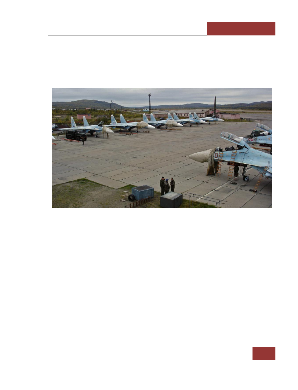
Figure 14: Su-27s in the Kilpyavr airbase (Kola Peninsula)
The ADF fighter regiment stationed in the Far East was the first line unit to adopt the Su-27. The
plant engaged in the aircraft mass production was situated in the same region, which made it
possible to be fast in tackling problems that inevitably arise at the outset of operation of any new
aircraft. Traditionally, Combat Employment and Personnel Retraining Centres (CEPRC) were the first
to fly out new fighters and work out recommendations as to their piloting and combat employment.
They were also responsible for retraining regimental pilots. That is why before the Su-27s became
operational in combat regiments, they had been delivered to the Lipetsk Air Force CEPRC and
Savostleika Air Defence CEPRC. In 1990, the centres operated 15-16 aircraft each. Later, the new
fighters entered service with another training unit - the training regiment of the Krasnodar-based
Higher Joint Flight Technical School.
According to the released information from the Data Exchange Protocol within the framework of the
CFE treaty, in late 1990, there were 367 such aircraft stationed in the European part of the USSR
with 138 fighters in the Air Force inventory and 229 aircraft in service with the Air Defence Forces
fighter regiments. Two Su-27 regiments as part of the Soviet Air Force were stationed abroad - in
Poland, on the Kluchevo-based and Khoina-based airfields; one - in Ukraine, in the city of Mirgorod.
The aircraft of the type were also operated by one of the squadrons of the composite air regiment
based in the Kubinka AFB. In 1991, an aerobatics team, which got a name of Russkiye Vityazi or
Page 24

DCS
[SU-27]
18
SU-27 HISTORY
Russian Knights, was established on the basis of that squadron, and later the Kubinka-based
regiment proper was reorganised into an Aircraft Show Centre named after Air Marshal I. Kozhedub.
The Leningrad, Arkhangelsk, and Tbilisi separate AD air forces operated two Su-27 regiments each
(airfields in the towns of Vainede, Nivenskoye, Killpyavr, Rogachovo, Krymsk, and Gudauta).
According to foreign estimates, in the early 1990s, the USSR operated approximately 600 Su-27s (to
all appearances, beside the Su-27 single-seaters based in the European USSR, that number included
the Su-27UB two-seat combat trainers as well as fighters stationed beyond the Urals).
Figure 15: Su-27P on the ramp
The break-up of the Warsaw Pact followed by dissolution of the Soviet Union led to the redeployment
and deactivation of a number of AF and ADF units including those that operated the Su-27 fighters.
Besides, almost 100 aircraft were left in the former Soviet republics of Ukraine and Belarus. In
summer, 1992, the air regiments of the former USSR left Poland. According to foreign analysts, in
early 1996, the Russian Air Force operated about 130 Su-27s, with approximately 300 aircraft in the
inventory of ADF units. Besides, 24 Su-27Ks came under the ship-borne fighter air regiment of the
Russian Navy in the Northern Fleet (part of the Su-27s were on board the Admiral Kuznetsov heavy
aircraft-carrying cruiser, with the rest stationed on the coastal airfield).
Page 25
[SU-27]
DCS
Eagle Dynamics
19
GENERAL DESIGN
GENERAL DESIGN
Page 26
DCS
[SU-27]
20
GENERAL DESIGN
GENERAL DESIGN
Design
The main feature for the success of the Su-27 design is its aerodynamic configuration, known as
'integrated aerodynamic concept' by its designers. This configuration is one with extremely blended
wing and fuselage. The low-aspect ratio trapezoidal midwing is fitted with large leading-edge root
extensions (LERX) and blending into the fuselage creating a single lifting body.
The aircraft has a near-zero static stability and thus require a fly-by-wire system. The SDU-10 pitchonly fly-by-wire system controls the pitch of the aircraft to ensure stability and controllability for the
pilot, increase aerodynamic performance, limit overload and angle of attack when needed and
decrease the airframe aerodynamic load.
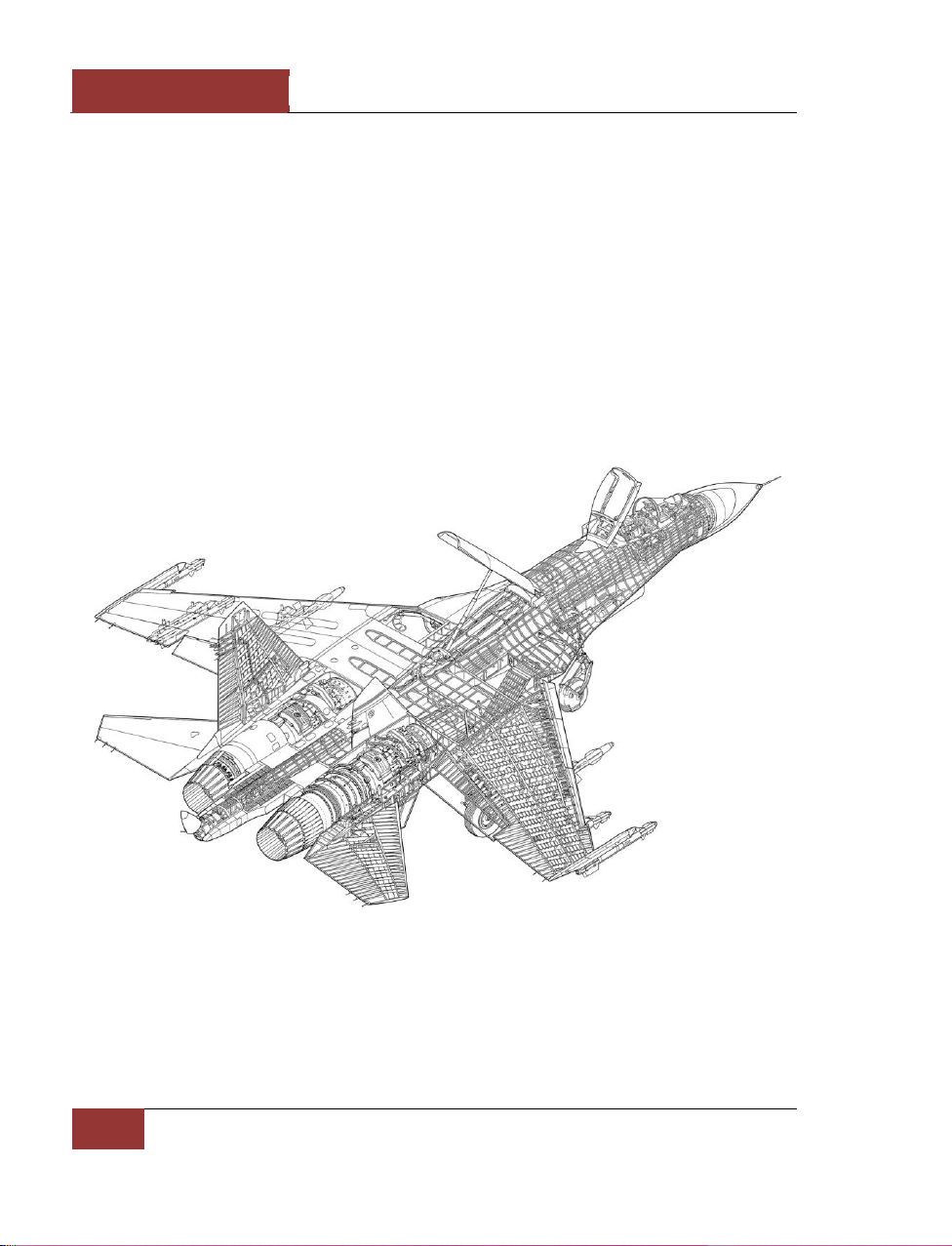
Figure 16: Su-27S cutaway
Two AL-31F afterburning turbofans are placed in seperate, widely spaced engine nacelles that are
mounted under the lifting body. The air intakes are fitted with variable ramps.
The Su-27 has twin vertical fins fitted on the outer sides of the fuselage and twin central fins
underneath. The airbrake is placed in the center of the mid-section of the aircraft behind the cockpit.
Page 27
[SU-27]
DCS
Eagle Dynamics
21
The tricycle landing gear of Su-27 and Su-27UB has a single wheel on each strut. The nose wheel is
fitted with a mudguard to protect against foreign object damage (FOD).
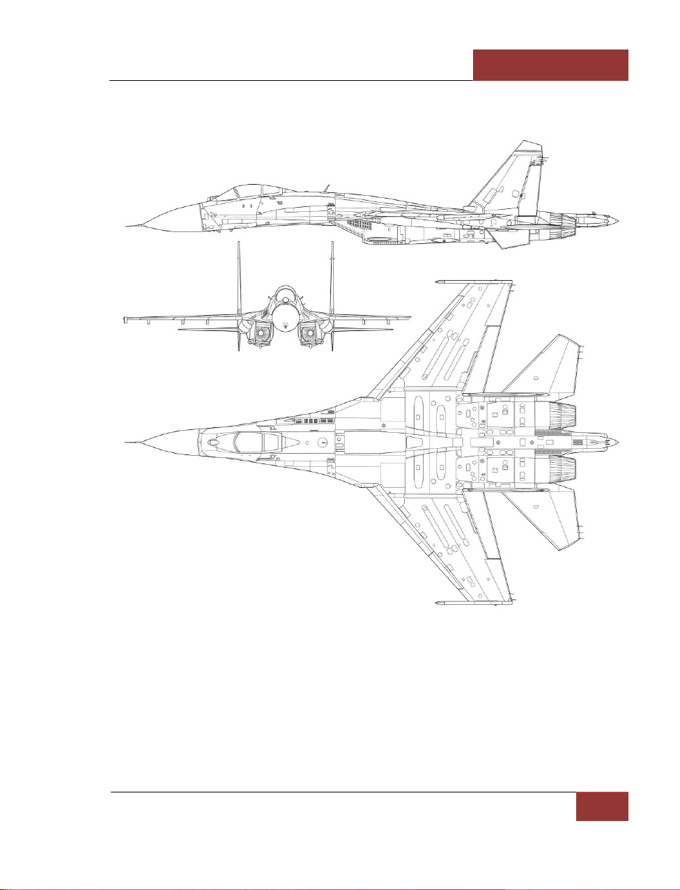
Figure 17: Su-27S
Page 28
DCS
[SU-27]
22
GENERAL DESIGN
Systems and Avionics
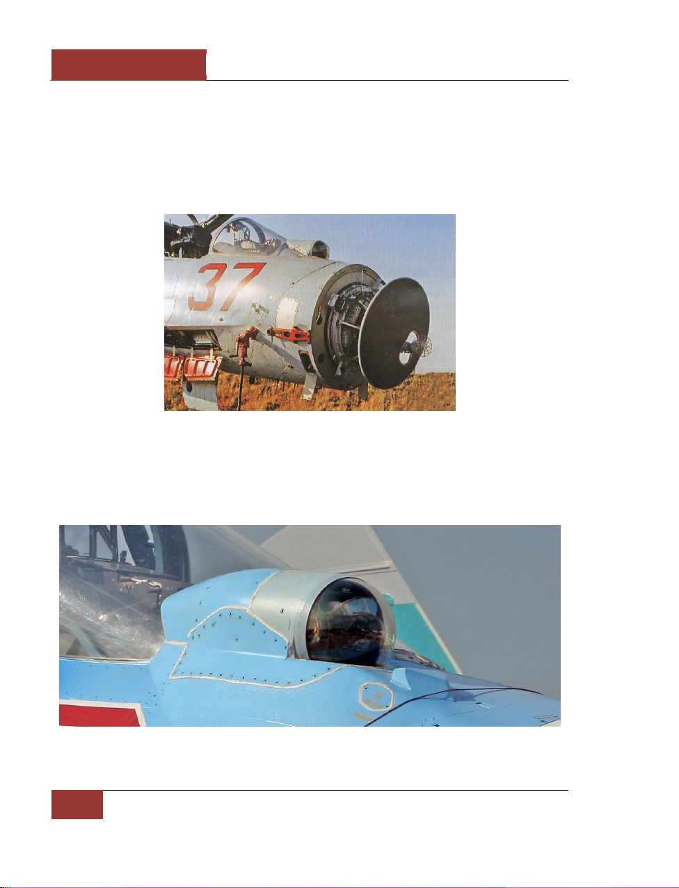
The basic Su-27 is fitted with the SUV-27 fire control system, which incorporates the RLPK-27 radar
sighting system, OEPS-27 electro-optical sighting system, SEI-31 integrated indication system, IFF
interrogator and built-in test system. The fire control system in integrated with the PNK-10 flight
navigation system, radio command link, IFF system, data transmission equipment and EW selfdefence system.
Figure 18: N001 radar
The RLPK-27 system and is controlled by the Ts-100 digital computer and includes the N001 pulseDoppler lookdown-capable radar with a range of 80-100 km in the front hemisphere and 30-40 km in
the rear hemispehere for a fighter-sized target. It can simultaneously track up to ten aerial targets in
track-while-scan mode and provide interception of the top priority target.
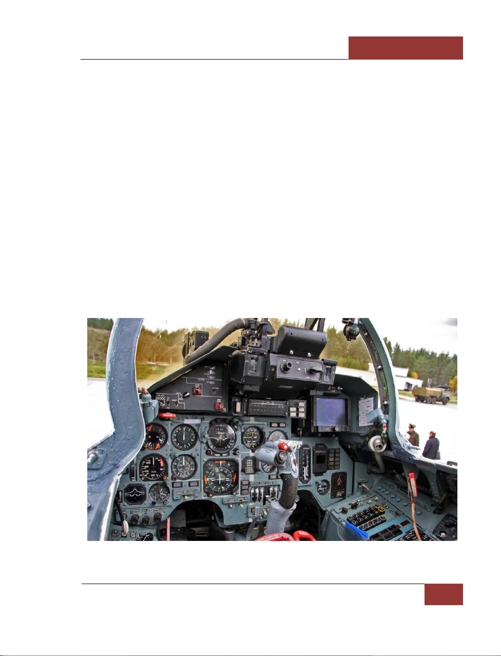
Figure 19: OLS-27 IRST
Page 29
[SU-27]
DCS
Eagle Dynamics
23
The OEPS-27 electro-optical sighting system consist of the OLS-27 infrared/laser search-and-track
system (IRST) and the Shchel-3UM helmet-mounted target designator and is controlled by the Ts100 digital computer. The OLS-27 sensor is placed forward of the cockpit canopy in the centre. The
system acquires and tracks aerial targets by their thermal signatures. The helmet-mounted sight and
the laser range finder of the IRST can also be used to visually acquire and determine coordinates of
air and surface targets.
The SEI-31 integrated indication system provides flight, navigation and sighting data on the ILS-31
head-up display (HUD) and head down display. The EW self-defence systems provides warning to the
crew when illuminated by enemy radar and employs both passive and active countermeasures The
aircraft is equipped with the SPO-15 Beryoza RWR and APP-50 chaff and flare dispenser that is
placed in the tail section between the engine nozels. In addition, the aircraft can carry the Sorbtsiya
active ECM pods on its wingtips.
Cockpit
The cockpit is fitted with the K-36DM Series 2 ejection seat. The seat-back is being inclined at an
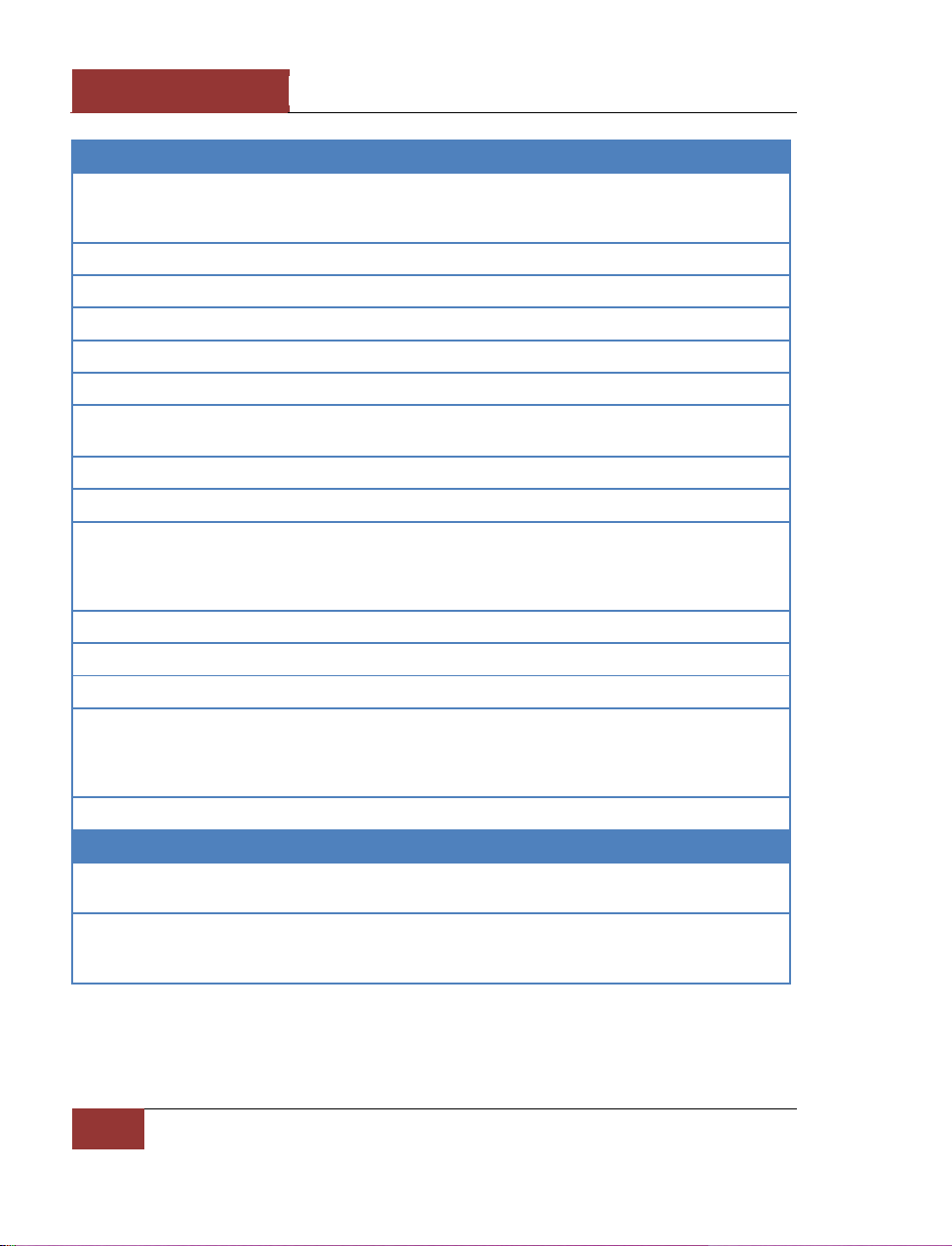
angle of 17 degrees. In the two-seat Su-27UB version, the seats are placed in tandem with the rearseat being elevated to ensure good forward vision. The basic Su-27 cockpit layout consist of
analogue instruments, HUD and head down display to display data from radar and electro-optical
sight (IRST). On both sides of the HUD control panel, there are sensors for the helmet-mounted
target designator system. On the right side below the head down display the RWR indicator is placed.
Figure 20: Su-27P cockpit
Page 30
DCS
[SU-27]
24
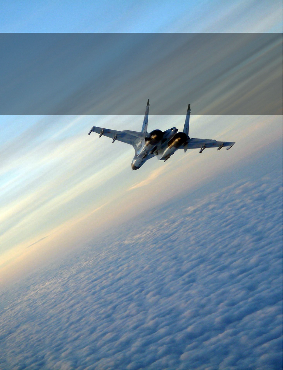
Aircraft performance
Takeoff weight:
- normal (including 2xR-27R + 2xR-73, 5270 kg fuel), kg
- maximum, kg
23,430
30,450
Maximum landing weight, kg
21,000
Landing weight limit, kg
23,000
Maximum internal fuel, kg
9,400
Maximum ordnance, kg
4,430
Service ceiling (without external ordnance and stores), km
18.5
Maximum flight speed at sea level (without external ordnance and stores),
km/h
1,400
Max Mach (without external ordnance and stores)
2.35
G-limit (operational)
9
Maximum flight range (with missiles 2xR-27R, 2xR-73 launched at half
distance):
- at sea level, km
- at height, km
1,340
3,530
Maximum airborne time, hours
4.5
Take-off run at normal takeoff weight, m
450
Landing run at normal landing weight (with braking parachute), m
620
Aircraft dimensions:
- length, m
- wingspan, m
- height, m
21.9
14.7
5.9
Crew
1
Powerplant
Number and type of engines
2 x
AL-31F
Thrust:
- in afterburner, kgf
- at full power, kgf
12,500
7,670
Page 31
[SU-27]
DCS
Eagle Dynamics
25
GAME AVIONICS
MODE
GAME AVIONICS
MODE
Page 32

DCS
[SU-27]
26
GAME AVIONICS MODE
GAME AVIONICS MODE
The Game Avionics Mode provides "arcade-style" avionics that make the game more accessible and
familiar to the casual gamer.
This mode can be selected from the Gameplay Options tab or by setting the Game Presets to Game.
Figure 21: Game Avionics Mode Radar Display
The display, located in the top right corner of the screen is a top down view with your aircraft (green
circle) located at the bottom center of the display. Symbols located above your symbol are located in
front of you, symbols to the right and left are located to the side of you.
The images below illustrate the various features of the Game Avionics Mode. Note that you will see
different symbols depending what mode the aircraft is in: Navigation, Air to Air or Air to Ground.
Game Avionics Mode Radar Display
Page 33
[SU-27]
DCS
Eagle Dynamics
27
However, each mode will have the following data in common:
• Mode. Indicated outside of the top left corner of the display. This can show NAV
(navigation), A2A (air to air) or A2G (air to ground).
Mode keys:
o Navigation: [1]
o Air to Air: [2], [4] or [6]
o Air to Ground: [7]
• Radar Range. Outside the top right of the display is the current range setting of the easy
radar.
Radar range keys:
o Zoom in: [=]
o Zoom out: [-]
• True Airspeed (TAS). Outside the lower left of the display is the true airspeed of your
aircraft.
• Radar Altitude. Outside the lower right of the display is the radar altimeter that indicates
your altitude above the ground or water.
• Current Heading. Inside the display at the center top is your current aircraft magnetic
heading.
Page 34
DCS
[SU-27]
28
GAME AVIONICS MODE
Navigation Mode
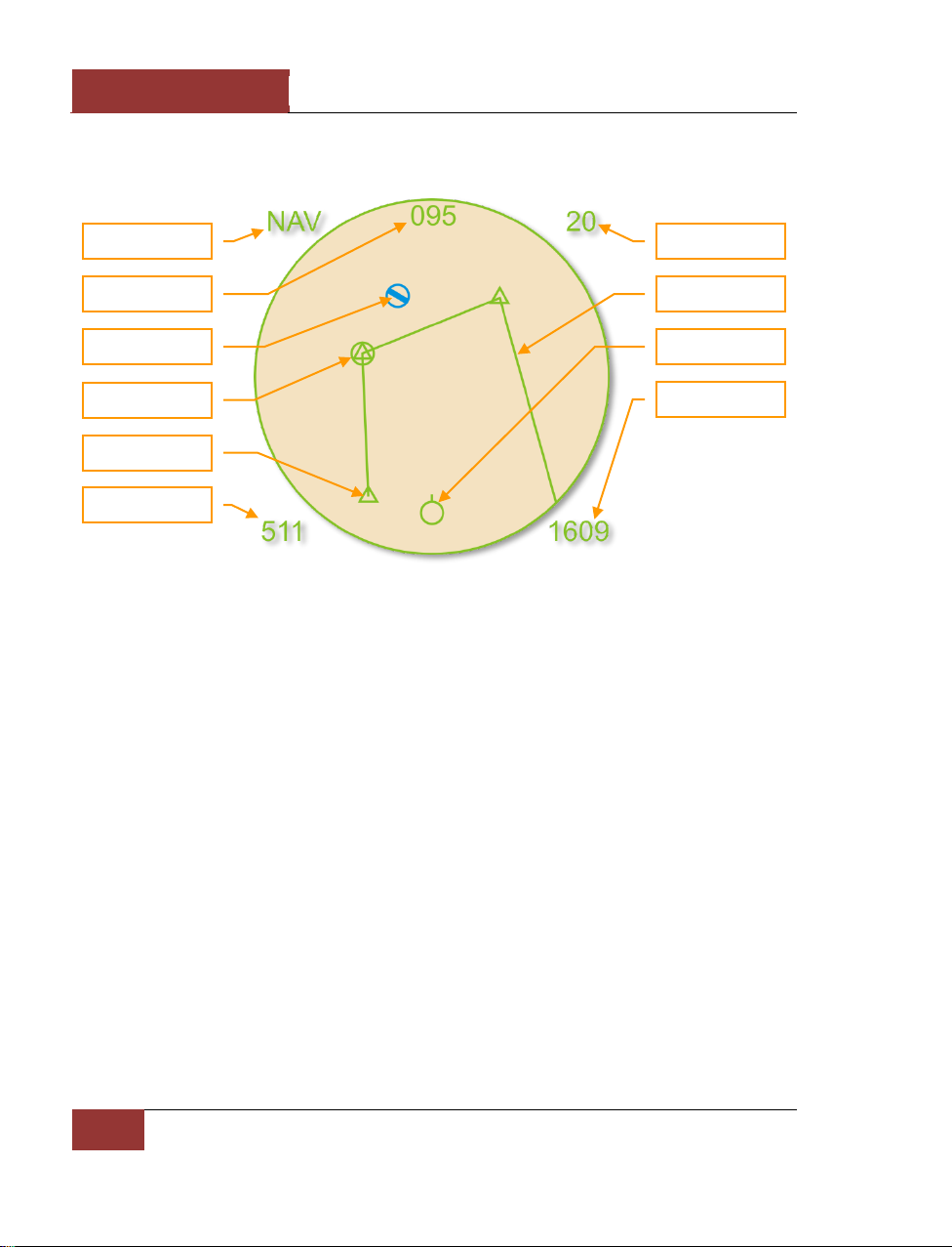
Figure 22: Navigation Mode
Unique symbols of the Navigation mode include:
• (Player symbol). Your aircraft is indicated as a green circle at the bottom of the display.
• (Friendly Airfield symbol). This blue symbol indicates friendly airfields.
• (Current waypoint symbol). This green circle indicates your current waypoint. You can
cycle your waypoint with the [LCtrl - ~] (tilde) key.
• (Waypoint symbol). This green triangle indicates other waypoints in your flight plan.
• (Route line). Green route lines connect the waypoints in your flight plan.
Navigation Mode
Current Heading
Friendly Airfield
Current waypoint
Waypoint
True Airspeed
Radar Range
Route line
Player
Radar Altitude
Page 35
[SU-27]
DCS
Eagle Dynamics
29
Air to Air Mode
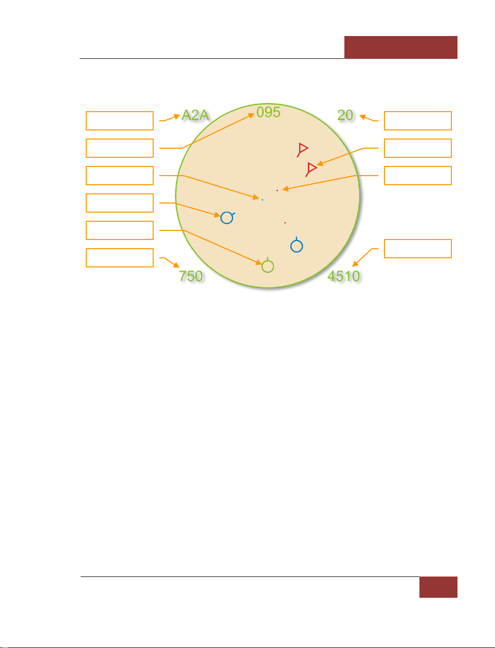
Figure 23: Air to Air Mode
Unique symbols of the Air to Air mode include:
• (Player symbol). Your aircraft is indicated as a green circle at the bottom of the display.
• (Friendly aircraft). All friendly aircraft are indicated as blue circles with lines coming from
them that indicate flight direction.
• (Enemy aircraft). All enemy aircraft are indicated as red circles with lines coming from
them that indicate flight direction.
• (Friendly missile). A friendly missile is indicated as a blue dot.
• (Enemy missile). An enemy missile is indicated as a red dot.
Useful key commands when in Air to Air mode include:
• Auto Lock Center Aircraft: [RAlt - F6]
• Auto Lock Nearest Aircraft: [RAlt - F5]
• Auto Lock On Next Aircraft: [RAlt - F7]
• Auto Lock Previous Aircraft: [RAlt - F8]
Air to Air Mode
Current Heading
Friendly missile
Friendly aircraft
True Airspeed
Radar Range
Enemy aircraft
Player
Radar Altitude
Enemy missile
Page 36
DCS
[SU-27]
30
GAME AVIONICS MODE
COCKPIT
INSTRUMENTS
COCKPIT
INSTRUMENTS
Page 37
[SU-27]
DCS
Eagle Dynamics
31
COCKPIT INSTRUMENTS
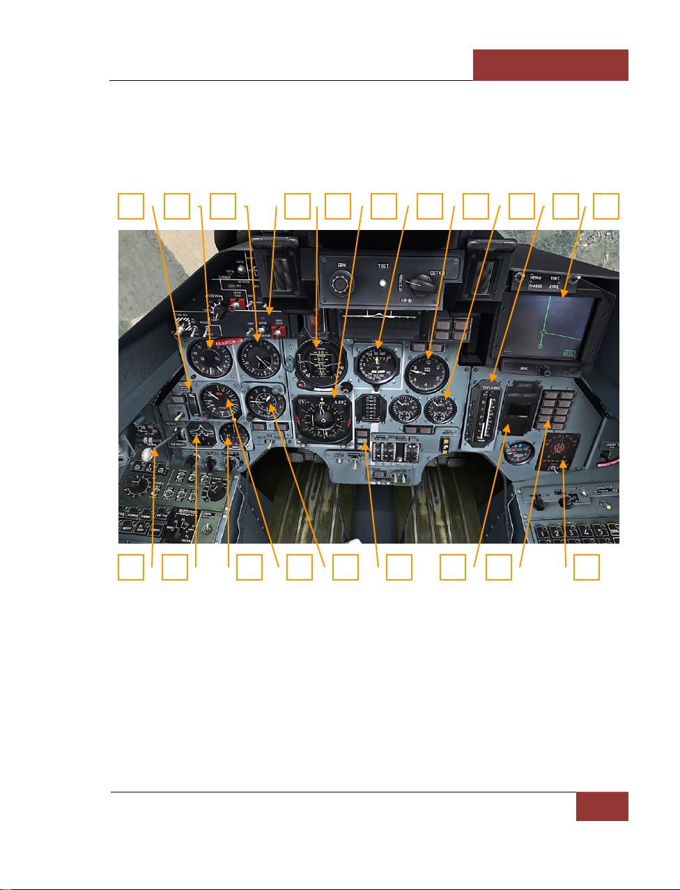
This chapter will instruct you about the Su-27 cockpit instrumentation. For successful piloting, you
must understand the function and position of all cockpit instruments.
Figure 24: Su-27 instrument panel
1. Wing leading edge flap position indicator
2. AOA indicator and Accelerometer
3. Airspeed and Mach indicator
4. Weapons control panel
5. Attitude Direction Indicator (ADI)
6. Horizontal situation indicator (HSI)
7. Vertical Velocity Indicator (VVI)
1 2 3
11
10 9 8 7 6 5 4
12
13
20
19
18
17
16
15
14
Page 38
DCS
[SU-27]
32
COCKPIT INSTRUMENTS
8. Tachometer
9. Interstage turbine temperature indicators
10. Fuel quantity indicator
11. Head Down Display (HDD)
12. Landing gear control valve
13. Mechanical devices indicator
14. Clock
15. Radio altimeter
16. Pressure altimeter
17. Trimming lights neutral position indicator in pitch, roll and yaw channels
18. "Ecran" integrated information system panel
19. Warning lights
20. SPO-15 "Beryoza" radar warning system
Airspeed and Mach Indicator
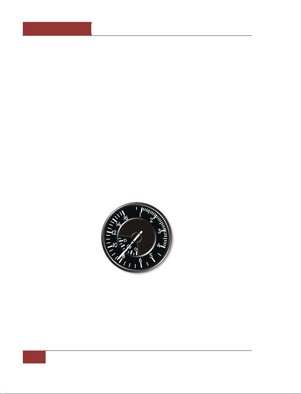
The airspeed and Mach indicator shows the indicated airspeed (IAS). The scale is graduated from 1
to 1,600 km/h. The Mach indicated in the interior of the gauge, scale is graduated from 0.6M to 3М.
Figure 25: Airspeed and Mach indicator
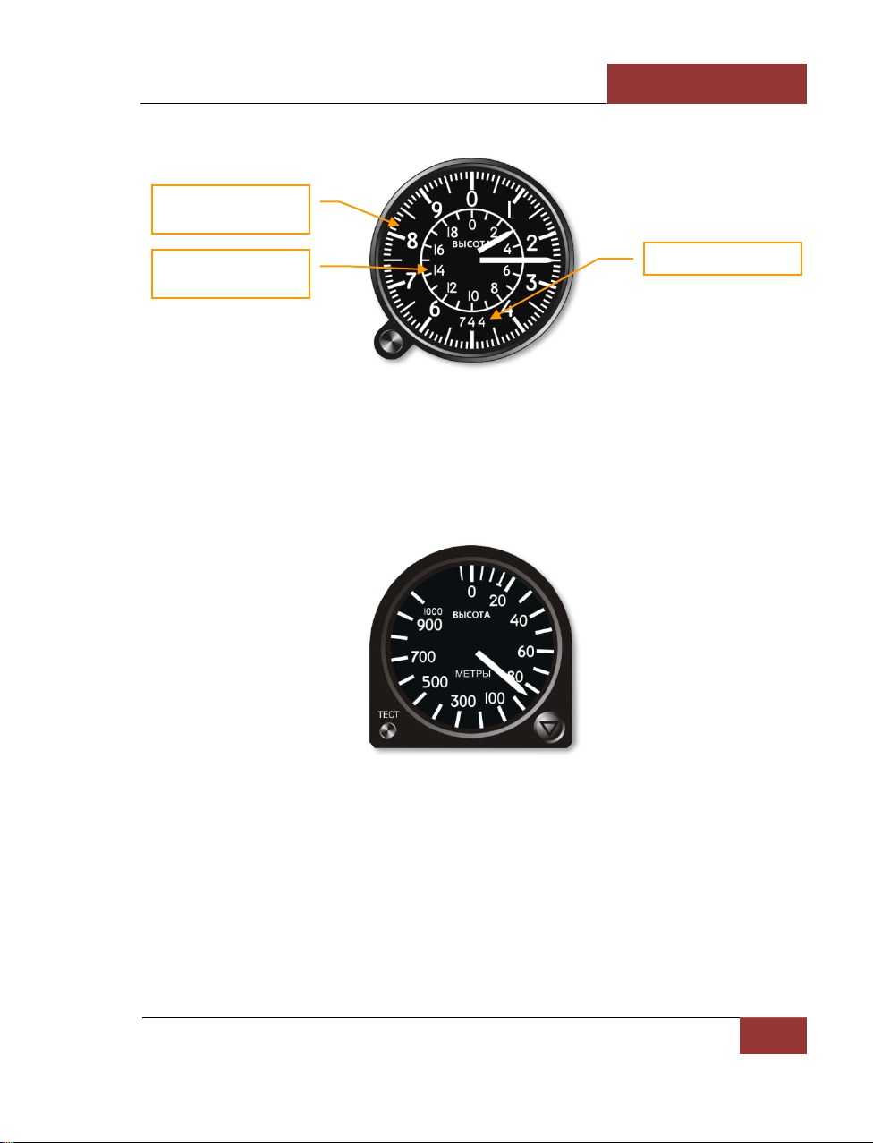
Pressure Altimeter
The barometric air pressure altimeter indicates the aircraft’s altitude above sea level. The Inner
altimeter ring scale is graduated from zero to 20,000 meters in 1,000 meter increments. The outer
altimeter ring scale is graduated from zero to 1,000 meters in increments of 10 meters. The aircraft’s
altitude is the sum of the readings of both scales.
Page 39
[SU-27]
DCS
Eagle Dynamics
33
Figure 26: Pressure altimeter
Radar Altimeter
The radar altimeter shows the aircraft’s altitude above ground, and therefore fluctuates according to
terrain height when flying straight and level. It measures heights from zero to 1,000 meters only.
Accurate readings cease with excessive bank.
Figure 27: Radar altimeter
Mechanical Devices Indicator
The mechanical devices indicator shows the position of the landing gear, flaps, intake FOD shields
and airbrake. If the landing gear is not extended or retracted, a red lamp lights in the center of the
indicator.
Hundreds meters dial
Thousands meters dial
QFE
Page 40
DCS
[SU-27]
34
COCKPIT INSTRUMENTS
Figure 28: Mechanical Devices Indicator
AoA Indicator and Accelerometer
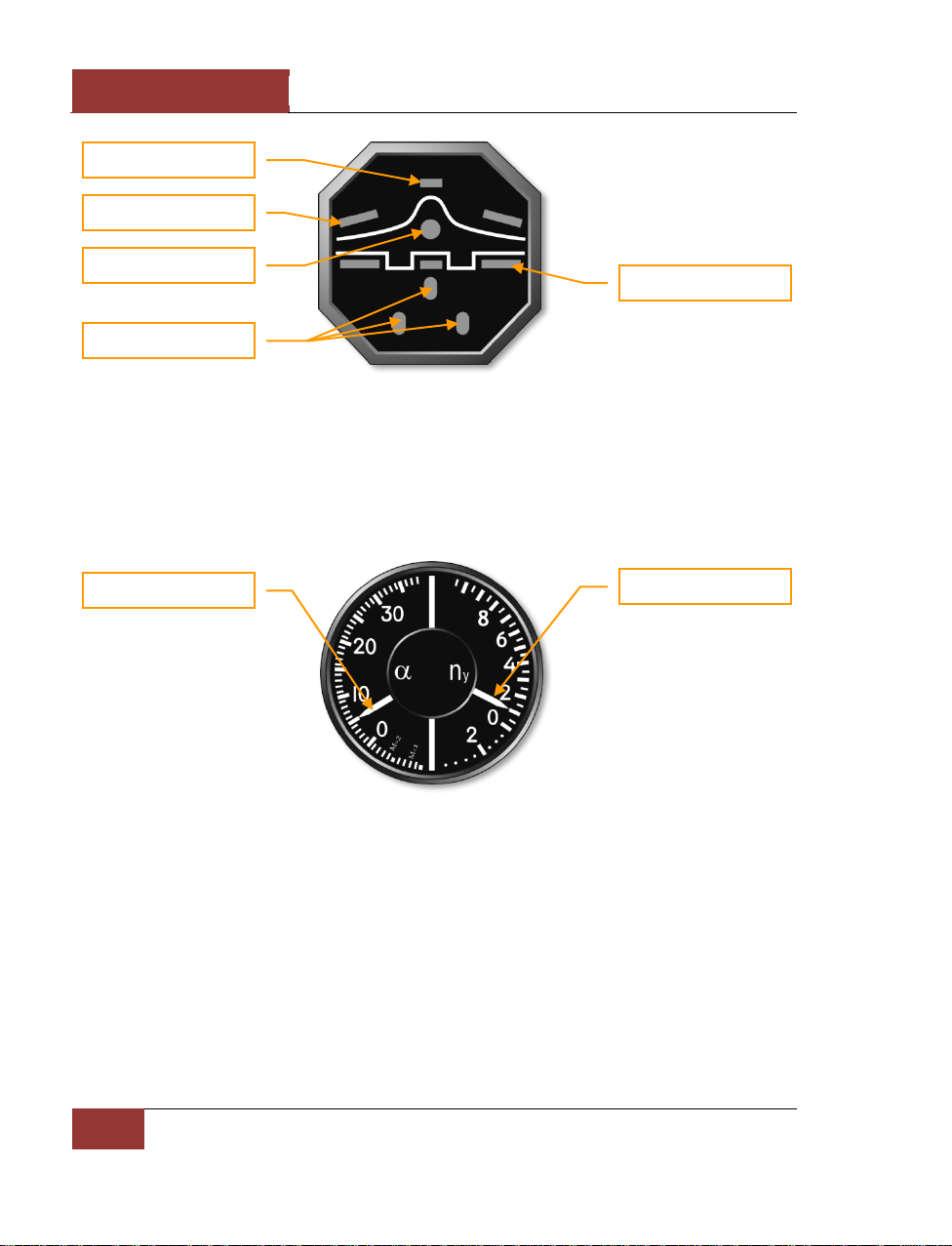
The Angle of Attack (AoA) indicator and accelerometer displays the current angle of attack and Gload. The left portion of the indicator shows the AoA in degrees and the right portion shows Gloading. An index mark shows the maximum G recorded during a flight.
Figure 29: AoA indicator and Accelerometer
Attitude Direction Indicator
The Attitude Direction Indicator (ADI) shows the current angles of pitch and aircraft roll. In the lower
part of the indicator is a yaw slip indicator. Changing the rudder position eliminates slipping, so try to
have the indicator in the central position. On the front portion of the indicator are the required bank
and pitch indicators to reach the next waypoint. When both yellow bars are in the central position,
the aircraft is following the correct route. During landings, the W-shaped glidescope deviation
indicator provides Instrument Landing System (ILS) direction.
Airbrake
Intake FOD shields
Flaps
Landing Gears
Landing Gears Warning
AoA indicator
G-loading indicator
Page 41

[SU-27]
DCS
Eagle Dynamics
35
Figure 30: ADI
Horizontal Situation Indicator
The Horizontal Situation Indicator (HSI) provides a top/down view of the aircraft in relation to the
intended course. The compass rotates so that the current heading is always shown at the top. The
Course Arrow shows the required heading and the Bearing Pointer points to the next waypoint.
Distance to the next waypoint and required heading are shown numerically at the top. The ILS
localizer and glide slope bars are in the center.
Figure 31: HSI
Required heading
Indicator
Pitch scale
Required bank
Required altitude
Required pitch
Aircraft datum
Bank scale
Slip indicator
Heading
Distance to waypoint
Bearing pointer
Required heading
ILS bars
Desired course arrow
Page 42
DCS
[SU-27]
36
COCKPIT INSTRUMENTS
Vertical Velocity Indicator
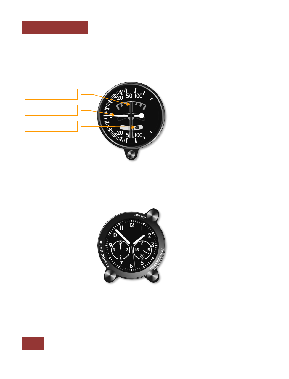
The Vertical Velocity Indicator measures the aircraft’s vertical speed, i.e. rate of climb or sink. The
Slip Indicator backs up the slip Indicator on the ADI. The Bank Indicator shows the rate of bank,
though the rate of bank shown is only approximate.
Figure 32: Vertical velocity indicator
Aircraft Clock
The aircraft clock shows the current time as set in the Mission Editor.
Figure 33: Aircraft clock
Bank indicator
Vertical velocity indicator
Slip indicator
Page 43
[SU-27]
DCS
Eagle Dynamics
37
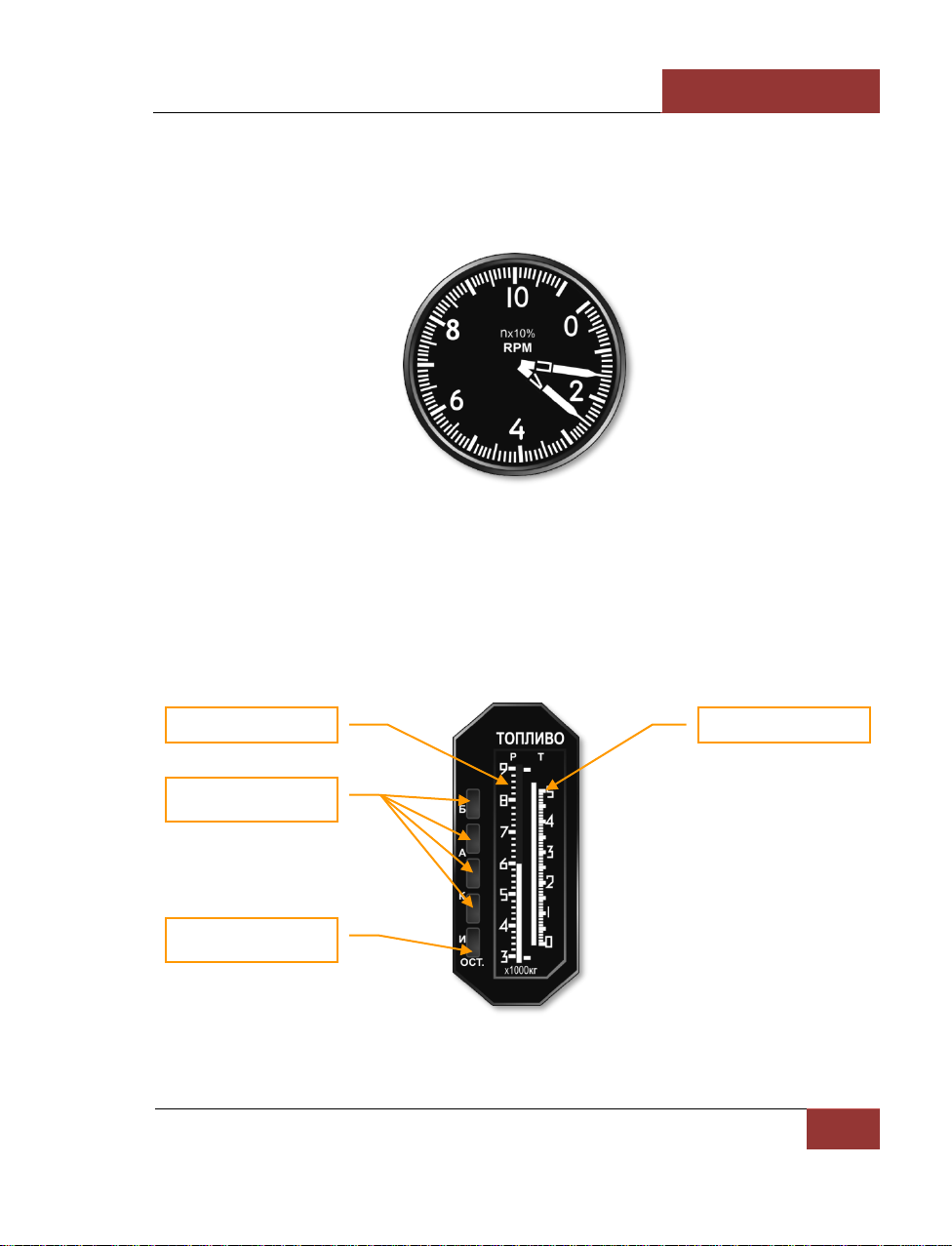
Tachometer
The Tachometer measures the RPM of both engines and is shown as a percent of maximum RPM.
Full afterburner power (reheat) is shown above 100%. When full afterburner is on, green lights show
above the Tachometer.
Figure 34: Tachometer
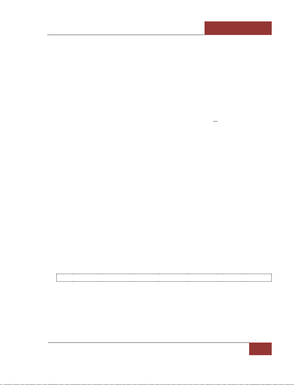
Fuel Quantity Indicator
Fuel quantity (P) shows the fuel remaining in all tanks. Fuel quantity (T) shows the fuel remaining in
the feeder tank.
If external fuel tanks are carried, a warning light indicates that they are about to be empty. Note that
the Su-27 cannot be loaded with external fuel tanks.
Figure 35: Fuel quantity indicator
All tanks fuel quantity
Tank warning
Emergency fuel
Feeder tank fuel quantity
Page 44

DCS
[SU-27]
38
COCKPIT INSTRUMENTS
Interstage Turbine Temperature Indicators
The two Interstage turbine temperature indicators show the temperature of the exhaust gas from the
left and right engine turbines.
Figure 36: Interstage turbine temperature indicators
Head Down Display (HDD)
The Head Down Display (HDD) is positioned in the right upper corner of the instrument panel. It
shows information about the preplanned route, waypoints and runway locations. In combat modes,
the radar and electro-optical system information is shown.
The scale of the HDD can be changed by the pilot.
Figure 37: HDD
Page 45
[SU-27]
DCS
Eagle Dynamics
39
Radar Warning System
Radars that are installed on aircraft, ships and ground vehicles are used for acquisition and weapons
guidance to various types of targets. Most modern aircraft are equipped with radar warning systems
(RWS) that detect the illumination of enemy radar. Although companies and bureaus have their
unique approaches to the designing of such systems, all RWS have common operational principles.
RWS is a passive system, i.e. it does not emit any energy into the environment. It detects radar
emitters and classifies them according to a database of the known radar types. RWS can also
determine the direction to the emitter and its operational mode. For example, the establishing a
single target track file. However, RWS cannot define the distance to the emitting radar.
For better situational awareness, it is recommended to use the RWS mode selection. Mode selection
enables the RWS to identify only radars operating in the target track mode, or radars that are
transmitting command guidance signals for a SARH missile launch or Active Radar Homing (ARH)
missile seeker track.
Note that the RWS does not have Identify Friend-or-Foe (IFF) capabilities.
The RWS can use priority logic to determine a primary threat and a list of secondary threats in
descending order:
1. The threat is either an ARH missile or if the missile command guidance signal is detected
(missile launch);
2. The threat radar is transmitting in Single Target Track (STT) mode (or any other lock
mode);
3. The threat has a priority based on a ‘common type’ of the threat. Here is the list of the
types:
• The threat is airborne radar;
• The threat is a long-range radar;
• The threat is a mid-range radar;
• The threat is a short-range radar;
• The threat is an early warning (EW) system;
• The threat is an AWACS.
4. The threat is at maximum signal strength.
RWS DOES NOT DEFINE THE DISTANCE TO THE EMITTER
SPO-15 Radar Warning System
The RWS indicates radars illuminating the aircraft. Information is presented as symbols of the types
and directions of the radars. Six indicator lights in the lower portion inform the pilot of the types of
radars illuminating the aircraft. The system warns of every radar; both adversarial and friendly.
The SPO-15 model implemented in game is very close to the actual system installed in the Su-27.
Page 46
DCS
[SU-27]
40
COCKPIT INSTRUMENTS
The system provides detection of radar signals at the following angles: Azimuth - +/- 180, and
Elevation Range - +/- 30.
The maximum number of threats on screen: Unlimited.
The threat history display duration time: 8 seconds.
Function modes: All (acquisition) or Lock (the "ОБЗОР/ОТКЛ" switch).
Threats types:
П – airborne radar
З - long-range radar
X - medium-range radar
H - short-range radar
F - early warning radar
C - AWACS
"Relative elevation" lights, "power of emission" gauge lights and "Lock/Launch" lights are only in
regards to the primary threat.
If the time between radar spikes of threat radar is eight or more seconds, the azimuth lights will not
blink.
In the case of an acquisition-type spike, the low frequency audio tone will sound.
If a radar is in lock mode, the "Lock/Launch" indicator will light up, along with a steady, high
frequency audio tone.
If a radar-guided missile launch is detected, the "Lock/Launch" light will flash, along with a high
pitched audio tone.
An ARH missile can be detected by the system after a missile establishes a lock using its own radar
seeker. In this case, the missile will become the primary threat. The cue to recognize an ARH missile
is the rapid increase in signal strength ("power of emission" lamps).
Page 47
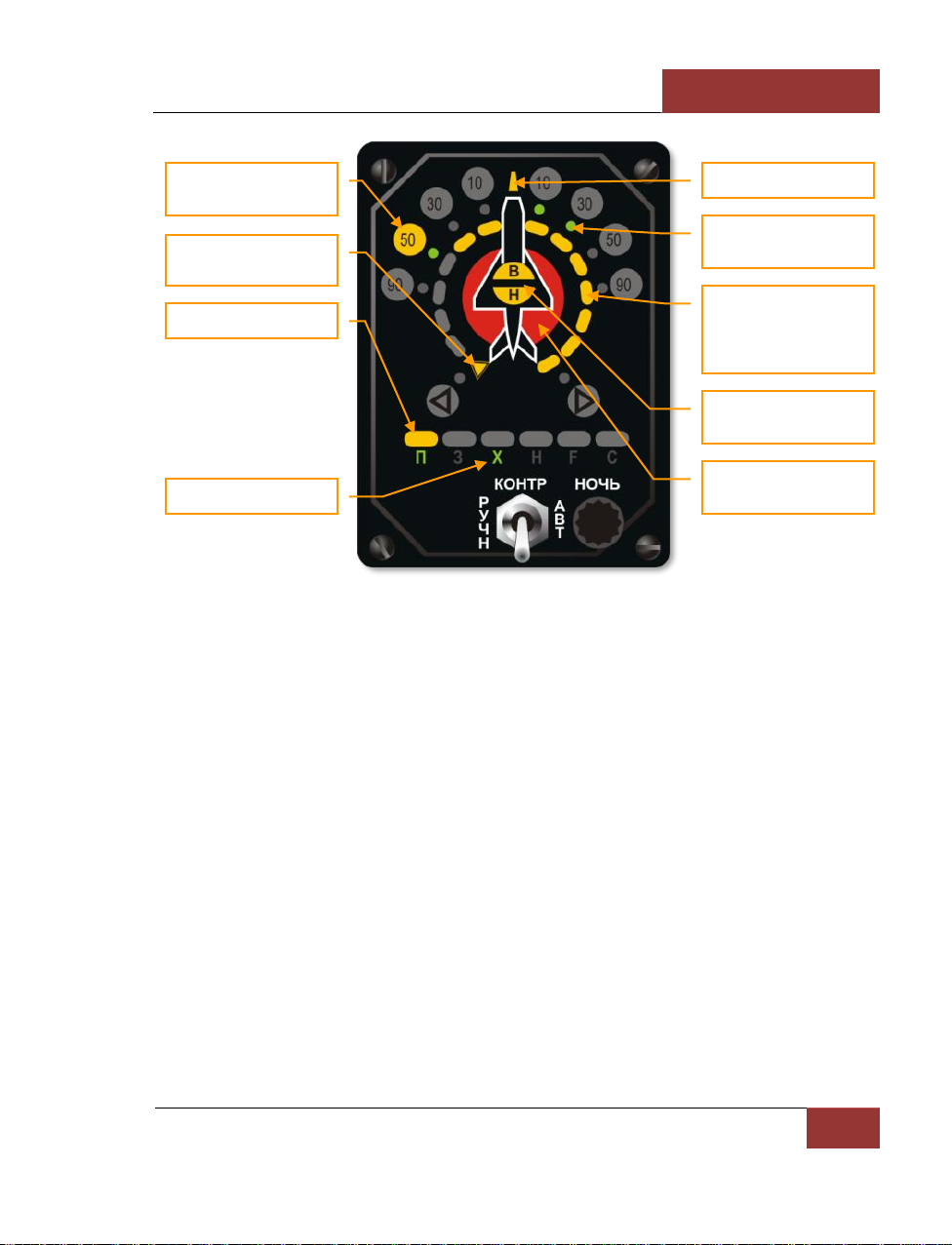
[SU-27]
DCS
Eagle Dynamics
41
Figure 38: "Beryoza" SPO-15LM indicator
The ability to correctly interpret the information indicated on RWS panel is vital in combat.
As an example, let’s take a look at the situation shown in picture above.
As is seen in the picture, two threats are indicated on RWS panel:
1. The primary threat at 50 degrees left (10 o’clock) is indicated in the form of a large yellow
lamp. The lamp above "П" symbol, which means "interceptor", is lit. This type of threat
includes all fighters. The circular scale of signal power ("light strip") consists of yellow
segments that show the relative emission power of the primary threat’s radar. The large
red circle under the aircraft symbol indicates that your aircraft has been locked by the
primary threat radar. The lit, yellow hemispheres marked as "В" and "Н" in the center of
the aircraft silhouette, indicates the threat’s relative altitude to yours. In this situation, the
primary threat is at the same altitude as your own, within 15 degrees in elevation.
Consequently, the display can be interpreted in the following way: your primary threat is a
fighter approaching from 10 o’clock; it is near co-altitude with you; and judging by the
signal strength and lock light, it is ready to launch a missile.
2. The secondary threat is positioned at 10-30 degrees azimuth (1-2 o’clock right), and this is
indicated by the two green lamps. The green "Х" symbol in the threat types line indicates
that your being targeted by a medium-range radar. There is no additional data on
secondary threats.
Direction to the primary
threat
Own aircraft mark on the
"light strip"
Primary threat type
Secondary threat type
Power light
"Light strip" - Relative
emmission power the
primary threat, estimate
range to threat
Relative elevation of the
primary threat
Red flashing lamp launch indication
Direction to the
secondary threat
Page 48
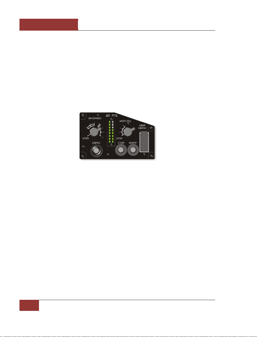
DCS
[SU-27]
42
COCKPIT INSTRUMENTS
In a complex threat environment, it is often difficult to define the threat type and its direction. In
this case, it is recommended to use the RWS mode filter [RShift-R] that removes all emitters
operating in acquisition mode.
The RWR can produce multiple audio alerts. You can adjust their volume by pressing [RAlt-,] –
[RAlt-.] keys.
PPD-SP Panel
On the right side of the cockpit is the PPD-SP control panel. In the of part of the panel is the PI-SP
indicator. This displays the remaining infrared flares and radar reflecting chaff bundles. The left
column indicates remaining chaff. One indicator light corresponds to 16 chaff bundles. The right
column indicates the number of remaining flares. One indicator light corresponds to eight flare
cartridges. Flares are released in pairs.
Figure 39: PPD-SP panel
Direct Control Switch
The DIRECT CONTROL mode is switched on by pressing the [S] key in the event that the fly-by-wire
system fails. Piloting in this mode requires special care; the flight is characterized by:
• Insufficient pitching stability
• Low aerodynamic damping
• Increased longitudinal stick sensitivity
It is in this mode that the “Pougachev’s cobra” aerobatic maneuver can be performed. The mode is
switched off by pressing the [S] key again. The on/off control can be checked by the switch on the
left panel in the cockpit.
Page 49
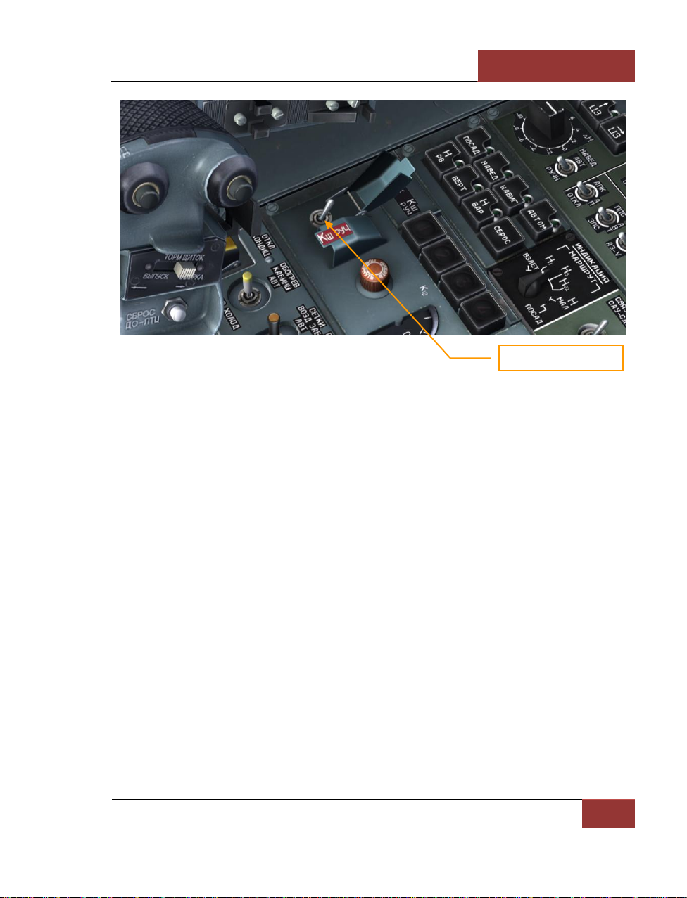
[SU-27]
DCS
Eagle Dynamics
43
Figure 40: Direct control switch
Trim Mechanism
Trimming of the aircraft control stick is performed by pressing the [RCtrl + .] and [RCtrl + ;] keys
in pitch and [RCtrl + ,] and [RCtrl + /] in roll.
To trim the rudder pedals, the [RCtrl + Z] and [RCtrl + X] keys are pressed.
Trim ranges are as follows:
• Pitch: 38% of backward stick travel and 50% of forward stick travel
• Roll: 50% on both sides
• Rudder pedals: 50% on both sides
The neutral position of the trim mechanism is controlled by three annunciators: “ТРИММ. СТ.
НЕЙТР.” (neutral stabilizer trim), “ТРИММ. ЭЛ. НЕЙТР.” (neutral aileron trim), and”ТРИММ. Р.Н.
НЕЙТР.” (neutral rudder trim) in the lower part of the main cockpit panel.
Direct control switch
Page 50
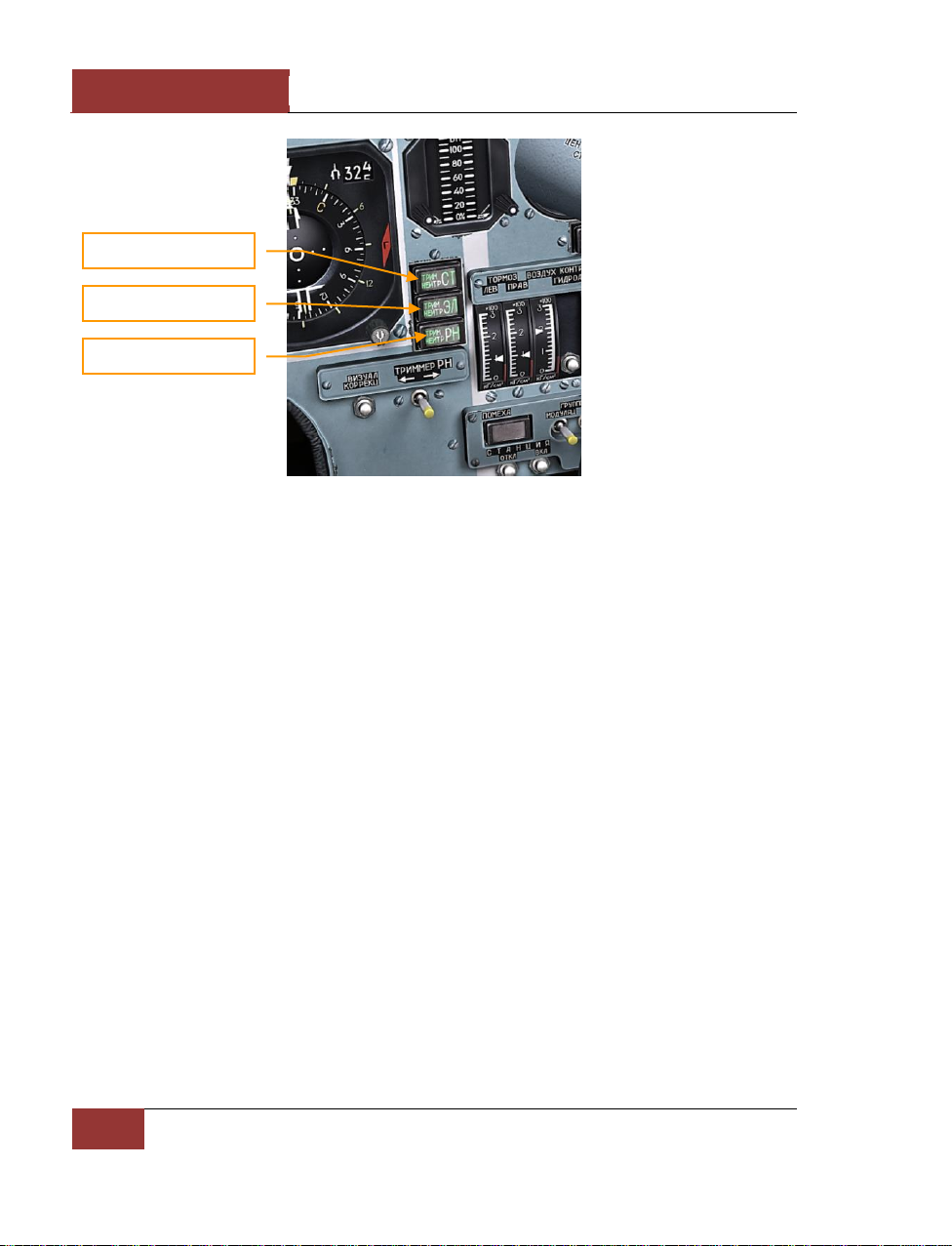
DCS
[SU-27]
44
COCKPIT INSTRUMENTS
Figure 41: Trim annunciators
Setting of the trim mechanism in the neutral position is activated by pressing [LCtrl + T]. This is
justified because there is no feeling of true loads of the controls, according to which real aircraft are
trimmed.
Holding the third joystick button [Joybutton3] is an alternate means to trim the aircraft. Joystick
operation is switched from virtual control stick deflection to trimming. In this mode, the joystick
deflections activate the control stick trimmer in the respective channel.
If a joystick has force feedback, trimming shifts the joystick neutral position, which is similar to how
the real Su-27 is trimmed.
Automatic Control System (ACS)
ACS provides:
• Autostabilization of pitch/bank and barometric altitude
• Automatic leveling of the aircraft in roll and pitch
• Stabilization of absolute altitude in accordance to the radar altimeter at altitudes between
100-1000 m, with automatic ground collision avoidance
• Automatic control of climbing and descending
• Automatic control in the horizontal plane in accordance with data from the navigation
system during enroute navigation mode
• Automatic return to the programmed airfield and landing approach down to the altitude of
50-60 m in accordance with input from the navigation system
Neutral stabilizer trim
Neutral aileron trim
Neutral rudder trim
Page 51
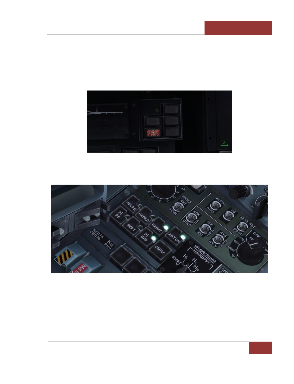
[SU-27]
DCS
Eagle Dynamics
45
Actuators of the fly-by-wire system and trim mechanisms are used as actuators of the automatic
control system (there are no separate ACS actuators).
Before turning on the ACS, the aircraft should trim (except for the "Level up to the Horizon" "Приведение к горизонту" mode). Deflection of the controls of more than 20% during the ACS
operation (or excess of pitch/bank angles of 80 degrees) disables ACS and places it in Manual Control
mode (except for the Level up to the Horizon) as the annunciator on the left part of the main cockpit
panel indicates. In this case, one should reset ACS by the "СБРОС" (RESET) pushbutton [Alt -9].
Figure 42: Manual Control annunciator
The ACS modes are controlled by push-light switches on the left console.
Figure 43: ACS push-light switches
The push-light switch “АВТОМ” (AUTO) will activate when any of the ACS modes (combined with
other push-light switches) is enabled. If this push-light switch is off, it means that the ACS is inactive.
If this push-light switch is the only one on, it means the attitude hold mode of the aircraft is active.
To control the ACS, the following commands are used:
Page 52
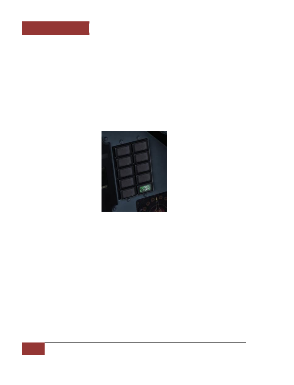
DCS
[SU-27]
46
COCKPIT INSTRUMENTS
[A] – Switches on the route following and barometric altitude stabilization modes. When the ACS is
active, this command pushes the "СБРОС" (RESET) button switching off any current mode including
the "УПРАВЛЯЙ ВРУЧНУЮ" (MANUAL CONTROL) mode and "УВОД НА ВЫСОТУ" (GROUND
COLLISION AVOIDANCE MODE).
[H] – Switches on barometric altitude stabilization mode. This is only possible when the bank angle is
less than 8 degrees and the heading is stabilized.
[LAlt-1] – Switches on the attitude hold mode (push-light switch "АВТОМ" is on) if the bank angle
is less than 8 degrees and the heading is stabilized.
[LAlt -2] – An alternative command to enable barometric altitude stabilization.
[LAlt -3] – Level to the horizon. In this mode, the ACS is not switched off by control stick overriding
and it has no pitch and bank angle limits. If this mode is on, the push-light switch "ПРИВЕД К
ГОРИЗ" (Level up to the horizon) is on in the lower right portion of the front cockpit panel.
Figure 44: "ПРИВЕД К ГОРИЗ" (Level to the horizon) annunciator
[LAlt -4] – An alternative command to enable barometric altitude stabilization. Same as [H].
[LAlt -5] – Switches on the radar altitude stabilization mode at altitudes between 300 to 1000m. At
a radar altitude of less than 50 meters or vertical velocity of more than -15 m/s, the "УВОД НА
ВЫСОТУ" (GROUND COLLISION AVOIDANCE MODE) mode is engaged automatically the bank angle
is zeroized and attain positive pitch using a g-load of up to 4 units.
[LAlt -6] – Switches on the route following modes. Simultaneously, the pitch is stabilized based the
value at mode initiation is used.
[LAlt -9] –Pushing the "СБРОС" (RESET) button switching off any current mode, including the
"УПРАВЛЯЙ ВРУЧНУЮ" (MANUAL CONTROL) mode and "УВОД НА ВЫСОТУ" (GROUND
COLLISION AVOIDANCE MODE). It also resets an ACS failure.
Page 53

[SU-27]
DCS
Eagle Dynamics
47
Su-27 HUD and HDD Operational Modes
Basic HUD symbols
Regardless of the avionics mode, some HUD symbology is unchanged between modes. We will take
a look at the HUD in ROUTE mode.
Figure 45: HUD basic symbols
1. The Required Speed indicator displays the assigned airspeed for the current flight mode.
When in ROUTE mode, the Required Speed will be the assigned airspeed for the currently
selected route leg.
2. Indicated aircraft speed (IAS) is shown to the left of the scale. Above the current IAS, the
required airspeed is indicated. It depends on the flight mode, and in the case of route flight
mode, it shows the required aircraft speed.
3. Under the numerical speed indicators is a triangular index that shows longitudinal
acceleration. To the right – acceleration, to the left – deceleration.
4. In the center of the HUD there is an aircraft datum, indicating aircraft pitch and roll.
5. The navigation mark (large ring) shows the flight direction to follow the preplanned route
and altitude to the next waypoint. When it is in the center of the datum, you are on-route.
1. Required speed
2. IAS
3. Longitudinal
acceleration
4. Aircraft datum
5. Navigation mark
6. Flight mode
7. Required altitude
8. Current altitude
9. Heading
10. Pitch
11. Horizon line
12. Distance to selected
waypoint
Page 54
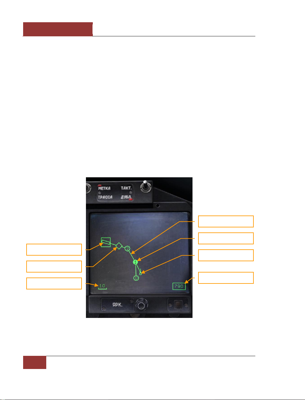
DCS
[SU-27]
48
COCKPIT INSTRUMENTS
6. In the lower left corner, the current flight mode is shown.
7. The Required Altitude value will vary depending on the selected flight mode. In ROUTE
mode, it will indicate the assigned altitude for the currently selected route leg.
8. To the right of the heading scale, the current altitude is indicated. For altitude less than
1,500 meters above ground level, the radio altitude is indicated to within 1 m. At an
altitude over 1,500 meters barometric, the height is shown to within 10 meters. Above the
scale the required altitude is shown. This will depend on the flight mode and in the case of
route flight mode, it shows the preplanned route altitude.
9. The current heading is positioned in the upper portion of the HUD. It shows the aircraft’s
current heading. (example: 11 corresponds to the value of 110 degrees).
10. The pitch ladder, situated in the right of the HUD, displays current pitch angle.
11. The artificial horizon line indicates a virtual horizon that corresponds to 0 degrees of pitch
and is intended to assist the pilot when flying in poor visibility conditions.
12. In the lower center part of the HUD, the distance to the selected waypoint is indicated in
Km.
When in navigation modes, information on the route (route direction, waypoints, and airfields) is
indicated on the HDD.
Figure 46: HDD in navigation mode
Glide slope capture point
Runway
Current waypoint
Route line
Your aircraft mark
Scale in kilometers
True air speed, km/h
Page 55

[SU-27]
DCS
Eagle Dynamics
49
• Waypoints are indicated by circular marks
• Waypoint number is indicated into waypoint mark
• Initial point for glide slope interception is indicated by a diamond
• Runways are indicated by a solid rectangle
• Current waypoint has inverted color
• All waypoints are connected by a route line
In navigation mode, navigation information is displayed on the HUD and HDD. There are three
navigation sub-modes: МРШ (ROUTE), ВЗВ (RETURN), ПОС (LANDING) and mode without
task. Switching between sub-modes is performed by successive presses of the [1] key.
The next route and waypoint will be displayed on HDD.
In ROUTE mode, the route line passes through all planned waypoints. To switch between waypoints
you can use the [LCtrl-~] key. The route line will connect your current position with the selected
waypoint.
In RETURN mode, the route line will lead to the glide slope intercept point.
In LANDING mode, the route line will lead to the desired air base. Airfield selection can be chosen by
cycling the [LCtrl-~] key.
Navigation Modes
When in the ROUTE sub-mode, a circular sighting mark is displayed on HUD; this shows the direction
to reach the current waypoint point. Above the airspeed and altitude indications are indicators for the
preplanned speed and altitude on a given route leg. When the current route point is reached, the
sighting mark will automatically switch to the next waypoint. Planned route and waypoints are
displayed on HDD.
In the RETURN sub-mode, the sighting mark shows the glide slope intercept point. The shortest line
to the glide slope point will be indicated on HDD. Manual switching between airfields is performed by
pressing the [LCtrl-~] key. After reaching the glide slope intercept point, the RETURN sub-mode will
automatically switch to the LANDING sub-mode and the Tower will provide landing instructions.
Page 56
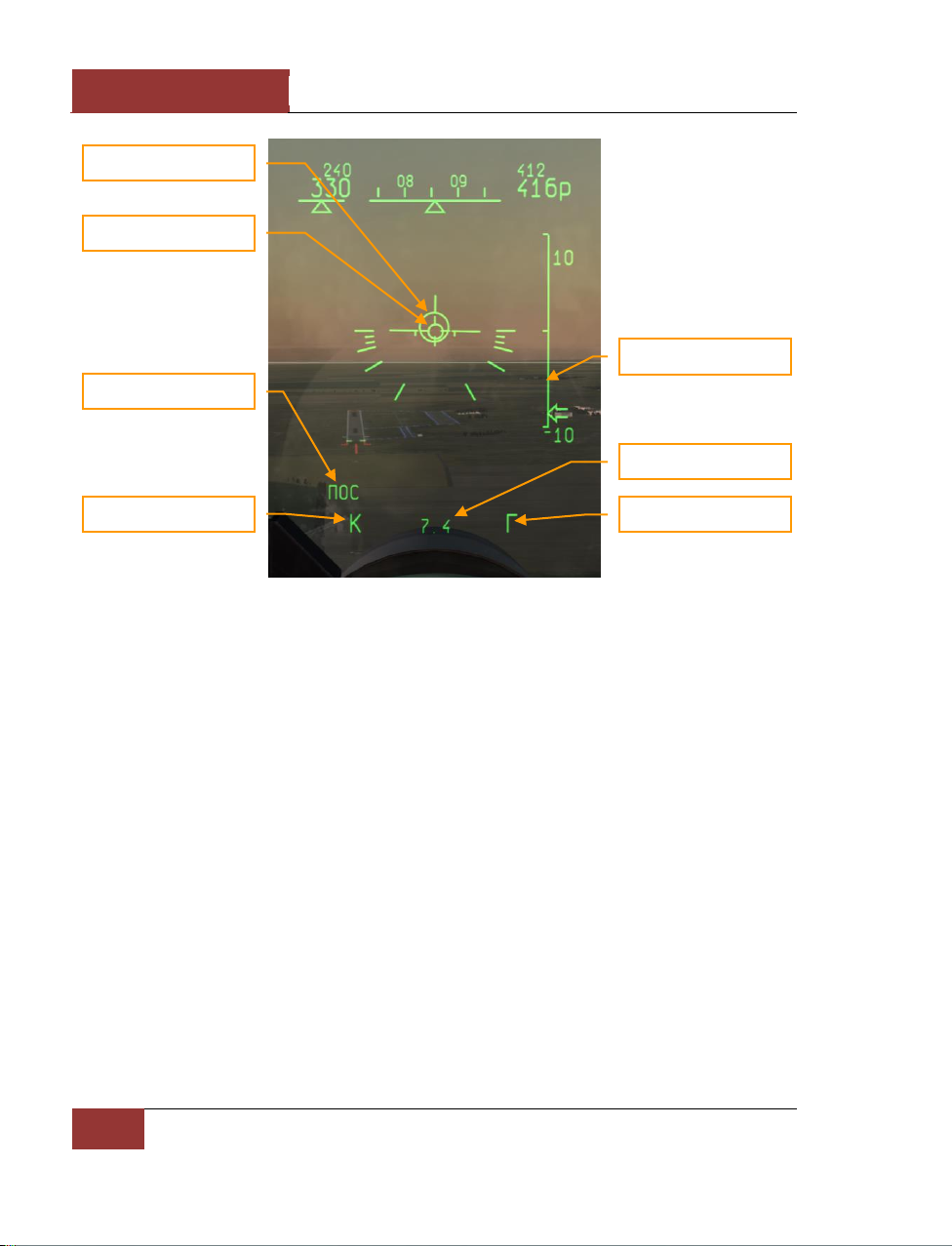
DCS
[SU-27]
50
COCKPIT INSTRUMENTS
Figure 47: ILS landing
In the LANDING sub-mode, the HUD director circle points to the landing airfield. The direction to the
landing airfield is also displayed on the HDD. Different airfields can be cycled with the [LCtrl-~] key.
A vertical velocity scale appears at the right side of the HUD to indicate the aircraft rate of descent.
Beyond Visual Range Combat Modes
There are several beyond visual combat (BVR) combat modes: "ОБЗ" (SCAN) – scan, "СНП" (TWS) –
track-while-scan, and "РНП" (STT) – single target track.
"ОБЗ" (SCAN) MODE
"ОБЗ" (SCAN) mode is first activated by pressing the [2] key. This is the primary BVR search mode.
Up to 24 targets can be detected. It’s also necessary to turn on one of the fire control sensors (radar
or IRST) before targets can be detected and engaged. In BVR mode, the fighter’s radar is normally
used. The radar enables target detection at longer ranges, and also the use of semi-active radar
homing (SARH) missiles.
Information necessary for target search and lock on is displayed on HUD. The range scale can be
controlled with the [+] and [-] keys. The scan pattern can be slewed discretely through three
azimuth positions, center – right – left. The scan pattern can be slewed in elevation using one of two
methods - smoothly by direct elevation slewing, or discretely by the range-angle method. To use the
range-angle method, first you should set the expected range to target in kilometers using the
[RCtrl-+] and [RCtrl--] keys, then set the expected target elevation difference with respect to your
ILS deviation mark
Navigation mark
Localizer beam index
Flight mode
Vertical speed scale
Glide-path localizer index
Distance to the runway
Page 57
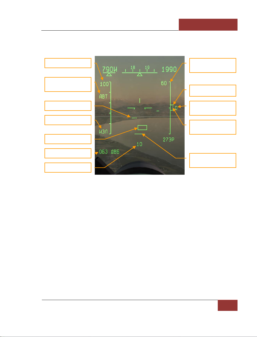
[SU-27]
DCS
Eagle Dynamics
51
aircraft using the [RShift-;] and [RShift-.] jeys, also in kilometers. The expected range you set is
indicated under the azimuth coverage mark at the bottom of the HUD, and the expected elevation
difference is indicated to the right of the elevation coverage mark on the right side of the HUD.
Figure 48: "ОБЗ" (SCAN) mode - BVR
When the fire control sensor detects a target, it is represented by a small, horizontal row of dots on
the HUD. "Friendly" targets responding to the radar’s identification system (IFF) are represented by
a double row.
• Range scale is changed by the [+] and [-] keys.
• The expected target aspect hemisphere is controlled with the [RShift-I] key. АВТ (ILV)
mode can be used if the target aspect is unknown. The expected target aspect determines
the pulse repetition frequency (PRF) to be used by the fighter radar in search mode. High
PRF (HPRF), which provides the longest detection range against approaching forwardhemisphere targets, is indicated by ППС (HI), whereas medium PRF (MPRF) for receding
rear-hemisphere targets is indicated by ЗПС (MED). In АВТ (ILV) mode, high and medium
PRFs are interleaved on alternate bars of the radar scan pattern. This provides all-aspect
target detection at the expense of a 25% reduction in maximum range.
• An air target is indicated on the HUD as a horizontal row of dots. The number of dots
corresponds to the approximate size of the target as measured by its radar cross-section
(RCS). One dot indicates a target RCS of 2 sq. m or less, two dots – from 2 up to 30 sq.
m, 3 dots – from 30 up to 60 sq. m, and four dots - 60 sq. m or more. Tactical fighters
typically have RCS values between 3 and 30 sq. m, dependent upon the type, external
Range scale
Target aspect hemisphere
(PRF)
Target mark
Radar active
Radar cursor
Expected target range
Radar elevation angle
scale
HUD view tick-marks
Relative target altitude
(expected)
Elevation
coverage bar
Azimuth
coverage bar
SCAN mode
Page 58
DCS
[SU-27]
52
COCKPIT INSTRUMENTS
payload, and aspect angle. Most fighters are thus usually displayed on the HUD as a row
of 2 dots. Friendly aircraft have an identification marking in the form of a second row of
dots positioned above the main one.
• The "ИЗЛ" symbol on the left side of the HUD indicates that the radar is turned on and
actively transmitting.
• The radar cursor for target designation is moved by using the [;], [,], [.], [/] keys.
• The expected (manual) range to target (often derived from AWACS and GCI data), as set
by [RCtrl-+] and [RCtrl--] keys and is indicated at the bottom of the HUD under the
azimuth coverage bar. The elevation coverage of the radar scan pattern is calculated from
this parameter.
• The expected relative altitude of the target with respect to your aircraft, as set by the
[RShift-;] and [RShift-.] keys is indicated on the right side of the HUD, next the
elevation coverage bar. This parameter is also used to calculate the scan pattern elevation
coverage.
IF YOUR FIGHTER IS AT AN ALTITUDE OF 5 KM AND AWACS REPORTS A TARGET AT RANGE 80 KM AND ALTITUDE
10 KM, YOU SHOULD TURN YOUR AIRCRAFT TOWARDS THE TARGET, THEN ENTER THE RANGE OF 80 KM AND
RELATIVE ALTITUDE 5 KM INTO THE RADAR. THE RADAR SCAN ZONE WOULD THEN BE CORRECTLY AIMED AT THE
EXPECTED TARGET ELEVATION.
• The elevation angle scale is also at the right side of the HUD. The scale limits are ±60
degrees, indicated by inwards facing tick marks at the top and bottom of the scale. A third
inward tick mark represents the horizon. Outward facing tick marks represent the viewing
angle of the HUD. Next to the fixed elevation scale is a moving elevation coverage bar,
which indicates the limits of the scan pattern in elevation. It cues the pilot to look in the
same direction as the radar scan pattern, using the HUD as a reference. If the elevation
coverage bar is between the HUD tick marks on the elevation scale, then the radar is
searching for targets in the elevation zone visible through the HUD.
• The azimuth coverage bar is displayed at the bottom of the HUD. It has three fixed
positions corresponding to the selected scan pattern azimuth: left – center – right.
Page 59
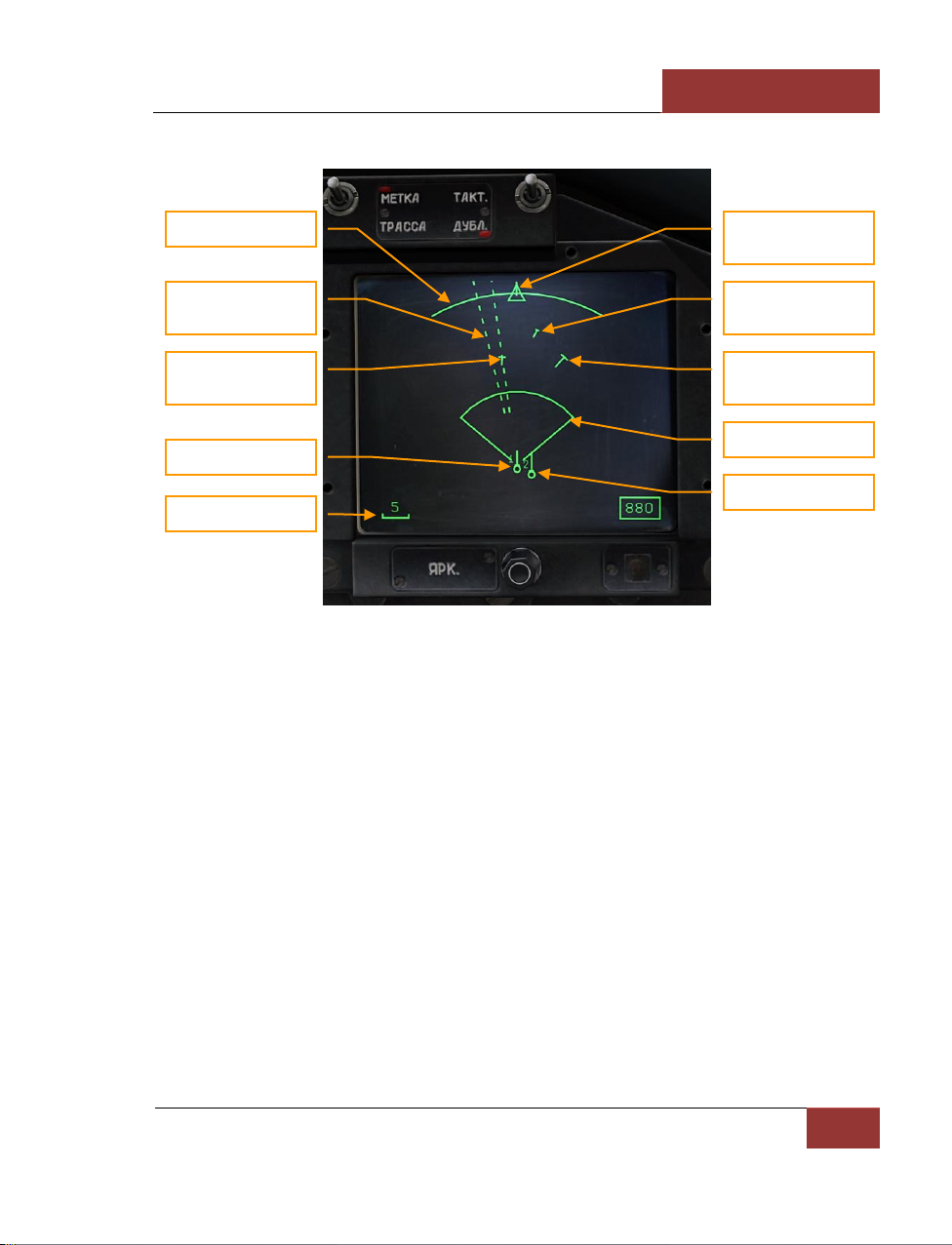
[SU-27]
DCS
Eagle Dynamics
53
The following information is displayed on the HDD in BVR modes:
Figure 49: HDD in BVR modes
• Scan arc (60 degrees) has 3 positions: center, left and right. The scan arc position is
corresponding with the azimuth coverage bar on the HUD.
• A target with jammer and unknown range is displayed with dash line
• Target using jamming but acquired range is displayed with mark and within a dashed line
• A target has a velocity vector and cross stroke. The length of velocity vector depends on
target's speed. Length of cross stroke depends on target's altitude.
• Circles denote friendly aircraft
• Your own symbol is fixed near the bottom, center of the HDD
• The display scale is indicated in the lower left corner
"СНП" (TWS) MODE
Another BVR combat mode is "СНП" (Track-While-Scan or TWS). It is activated from the "ОБЗ"
(SCAN) mode by pressing [RAlt-I]. The radar can correlate tracks for up to 10 targets
simultaneously in "СНП" (TWS). The main distinction from SCAN mode is that the radar retains
target parameters, like elevation and velocity vector, while continuing to search for additional targets.
Scan arc
Target with jammer,
without range
Target with jammer,
acquired range
Own aircraft
Lateral cross-track
error
Target, low speed,
low alrtitude
Target, high speed,
high alrtitude
Selected weapon DLZ
Wingman
Scale in km
Page 60
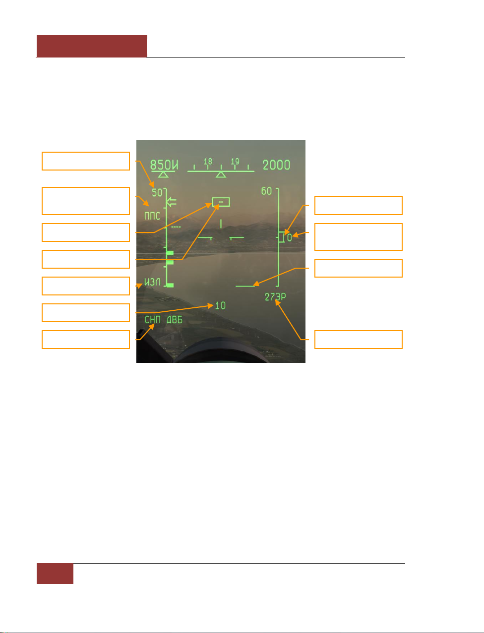
DCS
[SU-27]
54
COCKPIT INSTRUMENTS
The HDD provides a top-down view of the tactical situation including all tracked targets, together
with their direction of travel and position.
TWS mode provides automatic target lock on (transition to STT). This is enabled by moving the
radar cursor over a target. The cursor will "snap" to the target and follow it thereafter. Automatic
lock on occurs at a range equal to 85% of the calculated maximum weapon launch range. The pilot
can force an earlier lock on by pressing the [Enter] key.
Figure 50: "СНП" (TWS) MODE
The HUD symbology in "СНП" (TWS) mode is similar to that of "ОБЗ" (SCAN) mode.
• "СНП ДВБ" (TWS BVR) in the lower left corner of the HUD indicates the current mode.
• The chosen weapon is indicated in the lower right corner of the HUD, beneath the
elevation angle scale. The 27ЭР above indicates R-27ER missiles.
• The range scale at the left side of the HUD features three thick inwards facing tick marks.
Going from the top downwards, these are: Rmax - maximum permitted launch range vs.
non-maneuvering target, Rtr - maximum permitted launch range vs. maneuvering target
("no-escape zone"), and Rmin - minimum permitted launch range.
"СНП" (TWS) mode is only available together with "ППС" (Hi PRF) or "ЗПС" (Med PRF) selected. The
interleaved PRF "ABT" mode is not compatible. This mode therefore requires head-on or pursuit
target aspect to be known in advance.
Range scale
Target aspect hemisphere
(PRF)
Target mark
Radar cursor
Radar active
Expected target range
TWS mode
Azimuth coverage bar
Elevation coverage bar
Relative target altitude
(expected)
Selected weapon
Page 61
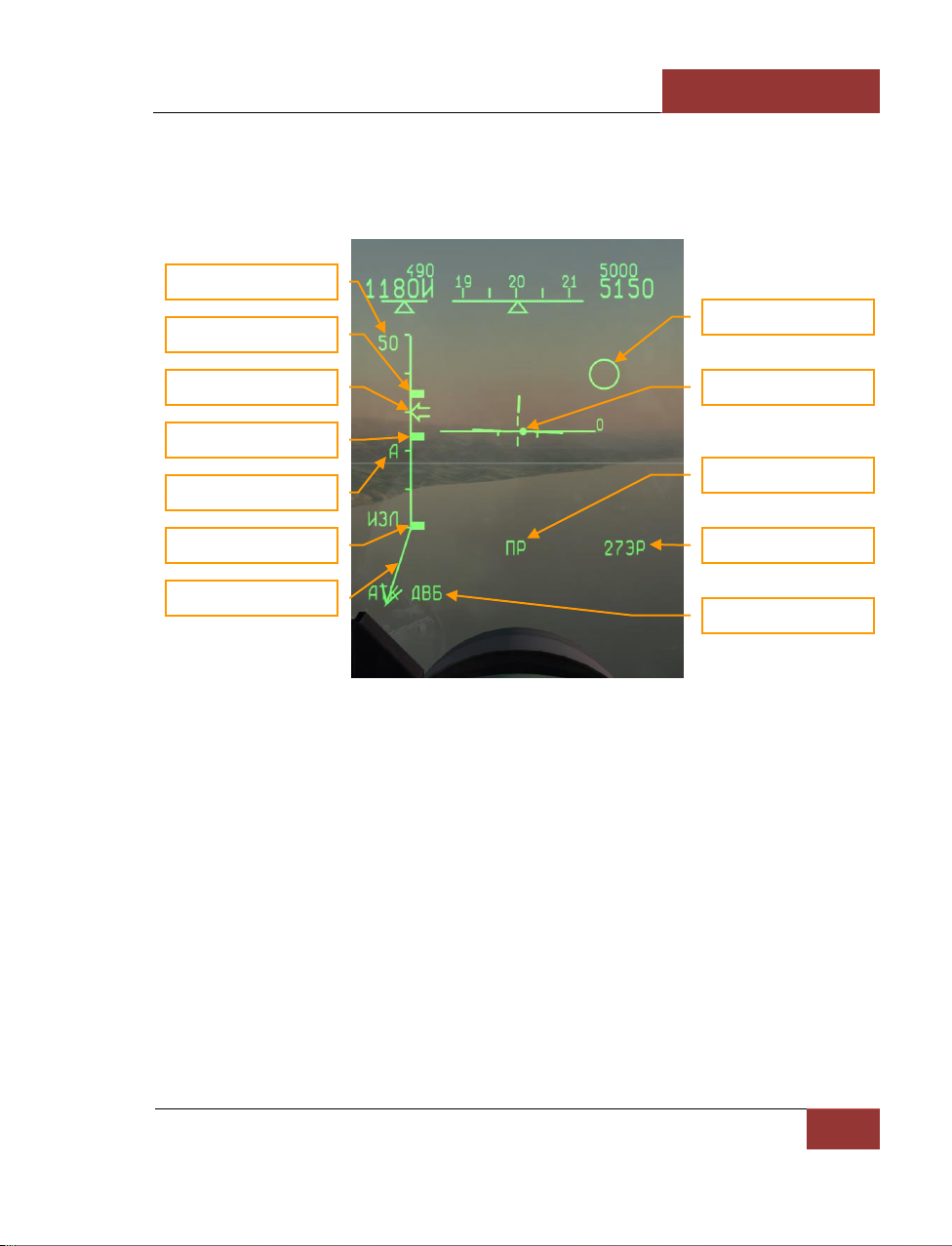
[SU-27]
DCS
Eagle Dynamics
55
"Атака – РНП" (ATTACK – STT) MODE
After locking up the target in either mode, SCAN or TWS, the radar automatically switches to Single
Target Track (STT) mode. It stops tracking all other targets and additional information is indicated at
the HUD in the following form:
Figure 51: "АТК ДВБ" (STT BVR) MODE
• Rmax – maximum permitted launch range vs. non-maneuvering target.
• Rtr - maximum permitted launch range vs. maneuvering target.
• Rmin – minimum permitted launch range.
• The attack symbol indicates an active radar lock. After missile launch, the attack symbol
flashes at a frequency of 2 Hz.
• Aspect angle shows target velocity vector in the plane turned in the HUD vertical plane.
• "АТК ДВБ" (STT BVR) mode is displayed in the HUD left lower corner.
• The arrow indicating current range to target moves along the range scale.
• A round dot indicates the radar antenna position relative to the fighter boresight.
• The target circle is superposed over the target in the HUD.
Range scale
Rmax
Rtr
Rmin
Aspect angle
STT
Current range
Radar antenna position
Target
Launch Authorized
Selected weapon
Radar lock-on
Page 62
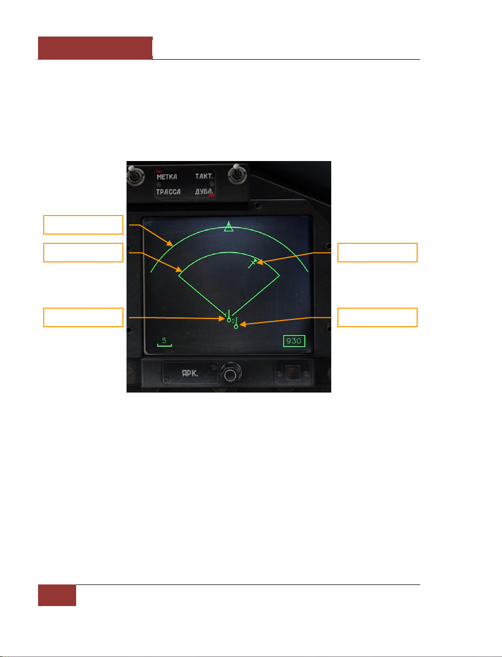
DCS
[SU-27]
56
COCKPIT INSTRUMENTS
• The "ПР" (LA) Launch Authorized symbol appears when the target enters the permitted
range limits and any other launch conditions are satisfied.
In STT mode, all radar energy is concentrated on a single target to provide greater accuracy and
reduce the probability of tracking loss, which may be caused by target countermeasures.
Note that this radiation-intensive mode is interpreted by enemy RWR as a "lock" and preparation for
missile launch. As a result, using it may prompt the target to take evasive action or to start a
counterattack.
Figure 52: HDD "АТАКА – РНП" (ATTACK – STT)
In the STT mode, the radar can lock one target and track it in 120 degree of azimuth.
The STT target mark has a solid triangle above it.
During missile launch, the radar changes to continuous wave illumination. This is unambiguously
interpreted by enemy warning systems as a missile launch and usually prompts some form of
defensive measures.
When semiactive radar homing (SARH) missiles like the R-27R and R-27ER are used, it’s necessary to
illuminate the target until the missile hits.
SCAN – IRST MODE
Use of the Infra-Red Search and Track (IRST) system as the chosen sensor changes the HUD
symbology accordingly.
Own aircraft
Target
Wingman
Tracking arc
Selected weapon DLZ
Page 63
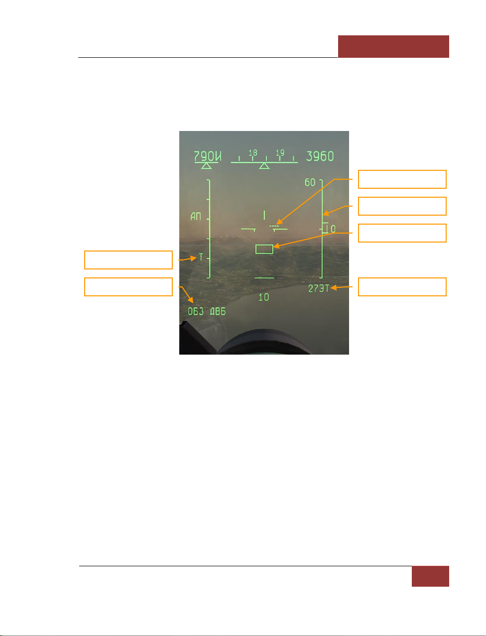
[SU-27]
DCS
Eagle Dynamics
57
When searching with IRST, target information is displayed in the HUD azimuth-elevation coordinates
(as opposed to the azimuth-range coordinates when searching with radar). Azimuth is along
horizontal, elevation angle along the vertical axes respectively.
After the locking the target with the help of the IRST cursor, the display switches to the STT mode
described earlier.
Figure 53: "ОБЗ ДВБ" (SCAN BVR) Mode with IRST as chosen sensor
• The "T" symbol at the left side of the HUD indicates IRST operation.
• The name of the chosen mode is displayed in the left lower corner.
• Target mark is displayed in the azimuth-elevation angle format.
Since the target’s RWR cannot detect the laser rangefinder employed by the IRST, this sensor makes
it possible to conduct a "stealth" attack. For this type of attack, only "heat-seeking" missiles with
seekers that employ infra-red homing (IRH) can be used.
Digital Datalink
The Su-27 carries radio equipment to receive digital target information directly from off-board
sensors (A-50 AWACS aircraft and ground-based EW radars) without using voice communications.
The command post transmits air combat tactical situation to the fighter, and this data is then
displayed in a top-down view on the HDD to improve the pilot’s situational awareness. This tactical
display shows the positions of all aircraft detected by off-board sensors, using the fighter’s own
IRST active
SCAN MODE
Target
Target mark
IRST cursor
Selected weapon
Page 64
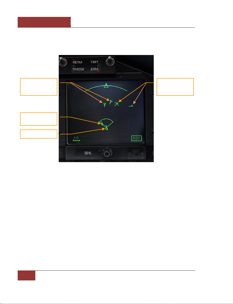
DCS
[SU-27]
58
COCKPIT INSTRUMENTS
position as a reference. The datalink is automatically active when the radar is first turned on ([I]
key), so long as a friendly AWACS aircraft or Early Warning (EW) ground radar station is available in
the mission. The datalink will remain active, and targets will continue to be displayed on the HDD,
even if the radar is thereafter switched off.
Figure 54: HDD with active AWACS datalink
It should be noted that some AWACS-detected targets appearing in the radar azimuth coverage zone
may not be visible to the radar if they are outside the radar elevation scan limits in altitude. The
fighter’s radar should be controlled with the help of the HUD display.
Work in Complicated Countermeasures Conditions
In complicated countermeasures conditions, when the enemy uses passive and/or active radar
jamming, the TWS mode cannot be used. SCAN mode should be used instead. In the conditions of
strong radio-electronic countermeasures the radar cannot determine the range to the target –
instead, a vertical jamming strobe of randomly flashing target marks appears in the HUD along the
jammer’s bearing. Detection of ECM in the radar scan pattern also causes the "АП" (ECM detected)
symbol to appear at the right side of the HUD. Nevertheless, it is possible to obtain a bearing-only
"angle-of-jam" (AOJ) lock on the countermeasures strobe and to launch semi-active radar homing
(SARH) missiles, which in this case will guide in the passive "home-on-jam" (HOJ) mode.
The AOJ lock is effected by using the [;], [,], [.], [/] keys to move the radar cursor over the
countermeasures strobe, and pressing the lock-on [Enter] key. The fighter radar will then point its
antenna in the direction of the noise source and track it. The target range displayed in the HUD with
Friendlies from
AWACS
Targets with open
triangle are reseived
from AWACS
Own aircraft
Targets with triangle
are acquired by own
radar
Page 65

[SU-27]
DCS
Eagle Dynamics
59
an active AOJ lock is not measured by the radar but rather provided by the fighter pilot (e.g.
according to instructions received by radio), with the default value 10 km. If the entered target
range is longer than the range of the chosen missiles for this altitude, then missile launch requires
either that the entered range is manually reduced with [RCtrl--] until the "ПР" symbol appears, or
that launch authorization override is enabled with [LAlt-W].
It should be noted that when using missiles against a jamming target, the lack of range information
can make it difficult to gauge when to shoot - the target may be outside the permitted launch zone.
In addition, missiles flying in the passive mode have a lower probability to hit the target.
At the range of less than 25 km to the jammer, the radar power is sufficient to "burn through" the
jamming and provide accurate target location, including range. The display on the HUD then
becomes the standard SCAN mode showing the distance to the target.
THE MOMENT WHEN THE FIGHTER RADAR CAN RECOGNISE THE REFLECTION OF ITS OWN SIGNAL ABOVE THE
JAMMING NOISE AND RECEIVE THE INFORMATION ON THE TARGET MOVEMENT IS CALLED "BURN-THROUGH".
WHEN THE RADAR STARTS TO PROVIDE FULL DATA ON THE TARGET DESPITE THE PRESENCE OF ECM, THE RADAR
HAS "BURNED-THROUGH" THE INTERFERENCE.
Figure 55: SCAN Mode with jammer strobe
• Blinking vertical countermeasures strobe is located at the jammer azimuth. Upon locking it,
the information on the HUD is similar to the STT mode with fixed mark of the current range
to the target.
ECM jamming detected
Countermeasures strobe
Radar active
Page 66
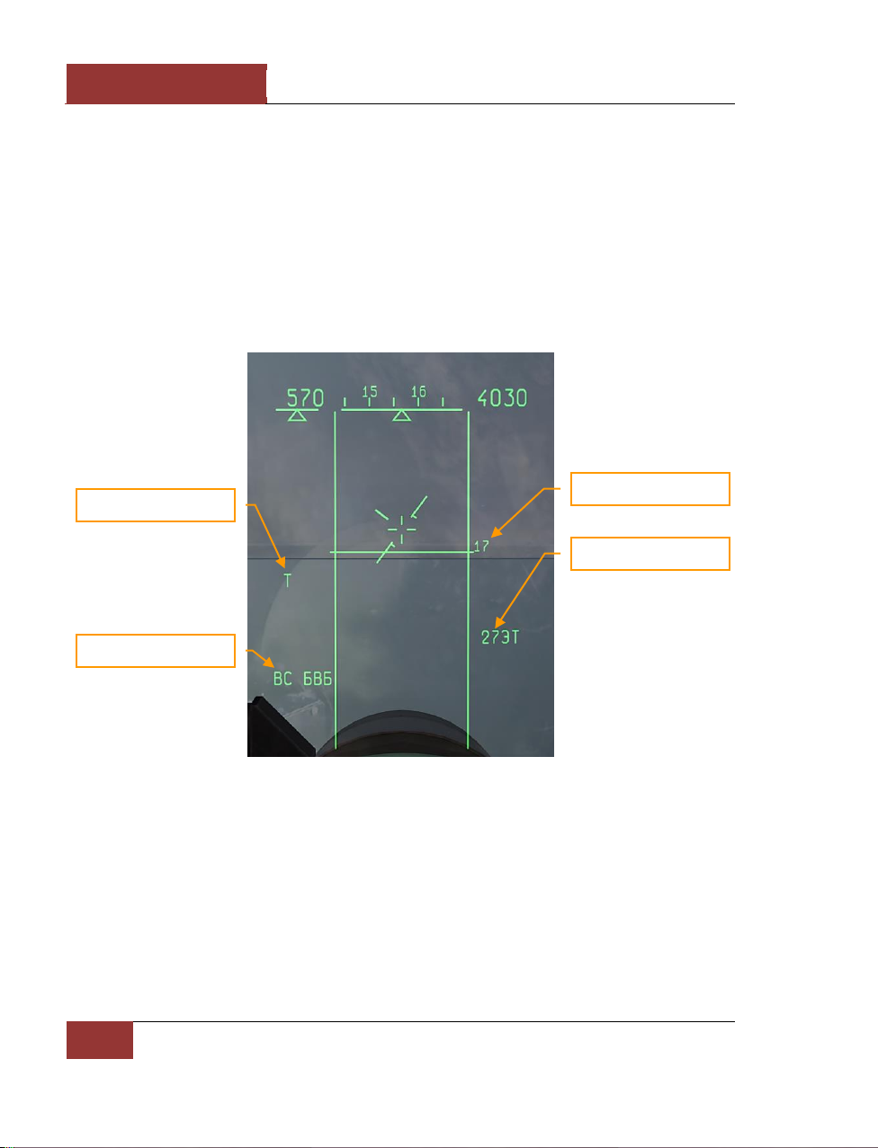
DCS
[SU-27]
60
COCKPIT INSTRUMENTS
• The "АП" active jamming indicator is displayed when electronic countermeasures are
detected in the fighter radar scan zone.
Vertical Scanning - Close Combat Mode
This Vertical Scanning sub-mode [3] is the most frequently used mode in close maneuvering air
combat. In this sub-mode, the radar or IRST scan pattern is a vertical bar that is -10+50 degrees
wide in elevation. The HUD displays two vertical lines denoting the boundaries of the scan zone.
Lock-on is possible when a target is inside the scan zone, which starts at the lower edge of the HUD
and extends above it by about two more HUD lengths. To lock-on a maneuvering fighter, fly to place
the target in the scan zone and press the lock-on [Enter] key. If the [Enter] key is not pressed, the
lock-on will not take place.
Figure 56: VS MODE
Lock-on occurs within 1 – 3 seconds of the target entering the scan zone with [Enter] pressed. After
the target is locked, the display on the HUD changes to the Attack (STT) mode.
Vertical Scan mode selects the IRST sensor by default. The default weapon is the IR missile. In
order to launch missiles with radar instead, the radar is first activated with the [I] key, and then the
desired missile is selected with the [D] key.
IRST active
Vertical scan
Pitch angle
Selected weapon
Page 67
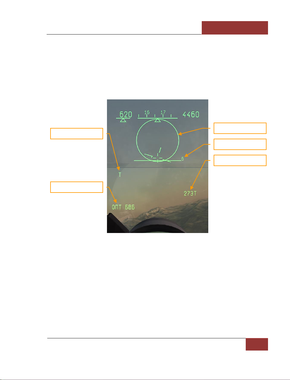
[SU-27]
DCS
Eagle Dynamics
61
BORE - Close Combat Mode
This sub-mode [4] is similar to VS mode, with the distinction that the sighting system does not scan,
but is rather bore sighted in one direction along the aircraft axis in a narrow (about 2.5 degrees)
cone. This zone is displayed on the HUD in the form of circle with the angular size of 2.5 degrees.
Target lock-on is accomplished by moving the circle over the target, either by maneuvering the
fighter or with the help of target designator control keys [;], [,], [.], [/], and pressing the lock-on
[Enter] key. After locking the target, the display on the HUD will change to Attack (STT) mode.
This mode provides good aiming precision and a slightly longer lock range than the VS mode.
Figure 57: BORE Mode
BORE mode selects the IRST sensor by default. The default weapon is the IR missile missile. In
order to launch missiles with radar instead, the radar is first activated with the [I] key, then the
desired missile is selected with the [D] key.
HELMET - Close Combat Mode
This unique mode is useful for maneuvering combat, and selected with the [5] key. The pilot can
aim weapons at the target simply by turning his head to look at it, with the help of the Schel-3UM
helmet-mounted sight (HMS). The sighting ring on the screen emulates the HMS sighting system
viewfinder located in front of the pilot right eye. The pilot can superpose the viewfinder over the
target by panning the view. The viewfinder is not a HUD symbol remains in the center of the screen
even when the view is panned off the HUD. This mode is used in close combat to get an advantage
IRST active
Lock-on zone
Pitch angle
Selected weapon
BORE mode
Page 68
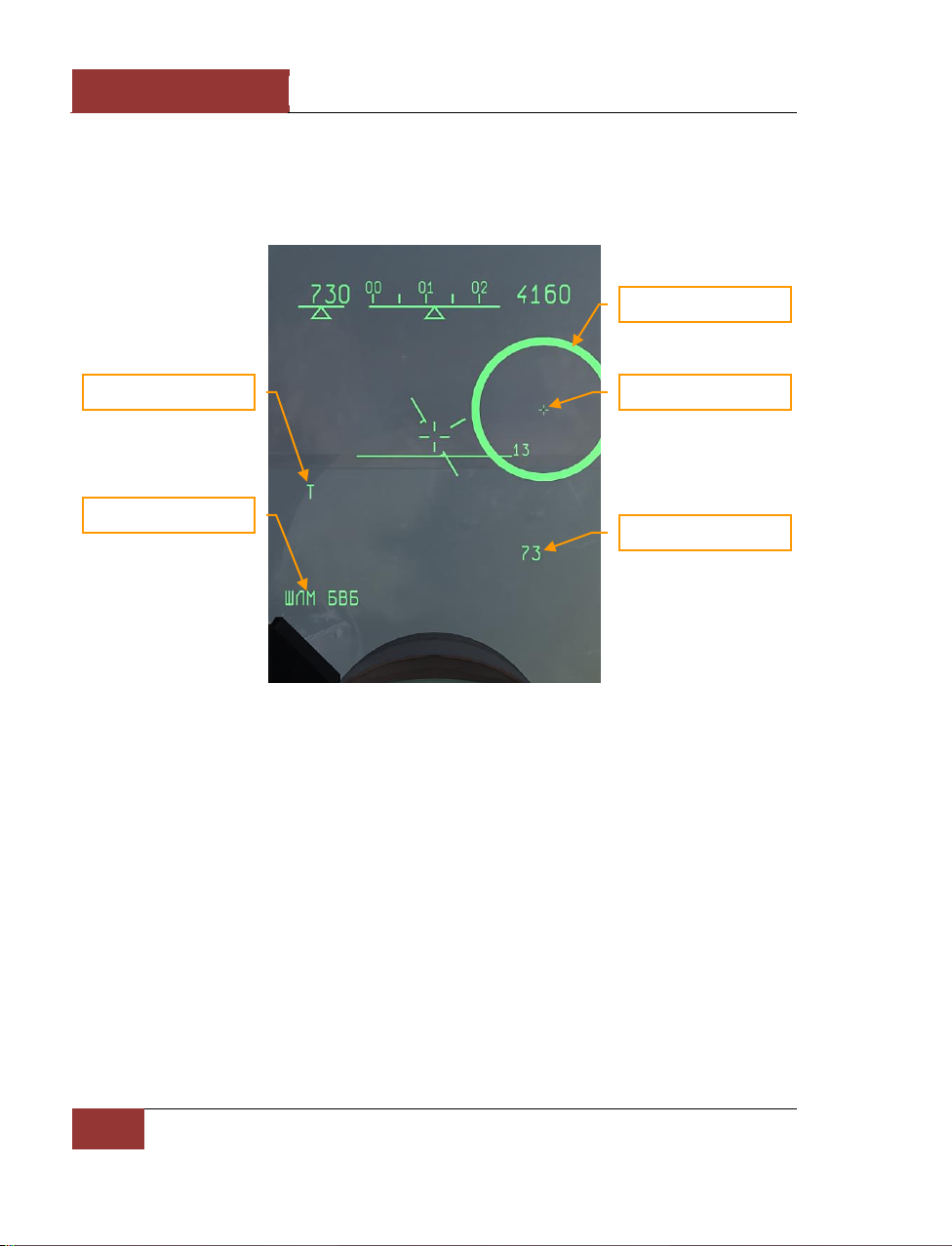
DCS
[SU-27]
62
COCKPIT INSTRUMENTS
in guided missile launch as HMS permits lock-on and missile launch from high off-bore sight angles,
without turning the whole fighter to point at the target. After locking the target by superposing the
sighting ring and pushing the [Enter] key, if all the launch criteria are satisfied, the ring starts
flashing at a frequency of 2 Hz, signaling "ПР" (launch authorized). If the target moves out of the
missile seeker’s angular gimbal limits, an "X" symbol will appear above the ring.
Figure 58: HELMET mode
The HUD display switches to Attack (STT) mode after locking the target.
It’s efficient to use the HMS mode together with the "padlock" view. First padlock the target with the
[NUM DEL] key, then select the HMS mode with the [5] key. The HMS ring will then be placed over
the target and it and be locked by pressing [Enter].
Fi0 – Longitudinal Aiming
Close Combat Mode
Fi0 (Fi-Zero) is a backup mode in case of failure of the fighter weapons control system (WCS) radar
and IRST sensors. This mode is selected with the [6] key, but can be used only with infra-red
homing (IRH) missiles which have seekers capable of acquiring the target independently of the
fighter’s sensors. In this mode the missile’s own seeker, which has a 2-degree conical field of view
looking forward along the missile axis, is used to lock the target. It’s necessary to maneuver the
fighter to place the aiming cross-hair over the target. The LA symbol appears immediately when the
IRST active
HELMET mode
HMS aiming ring
Target
Selected weapon
Page 69
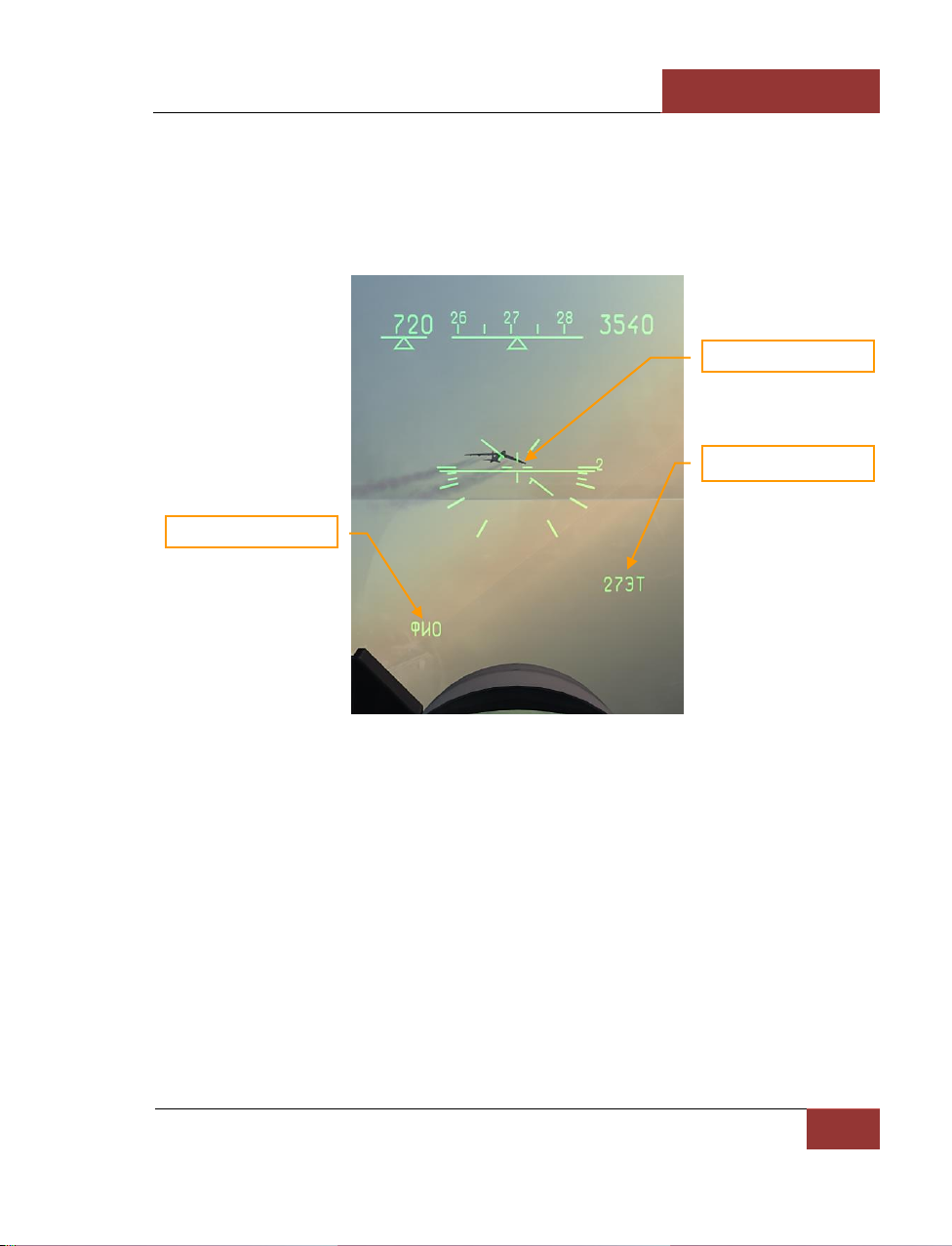
[SU-27]
DCS
Eagle Dynamics
63
missile seeker has locked the target, regardless of target range. The pilot should judge the target
range visually to ensure the missile will have enough energy to complete the intercept, especially in
the case of receding pursuit targets.
The use of infra-red homing (IRH) missiles in the Fi0 mode will not trigger the target’s RWR, and as
such can be used to affect a passive "stealth" attack. The target can detect the missile launch only
visually.
Figure 59: Fi0 (Longitudinal) MODE
Gun Employment
The aircraft cannon can be used in air-to-air combat mode. To do so, first select the cannon by
pressing the [C] key. Press the [Enter] key to lock the target with the active sensor when target is
visible in the HUD. If a sensor lock is present, the WCS will automatically enter the Lead Computed
Optical Sight (LCOS) mode.
Fi0 mode
Selected weapon
Aiming crosshairs
Page 70
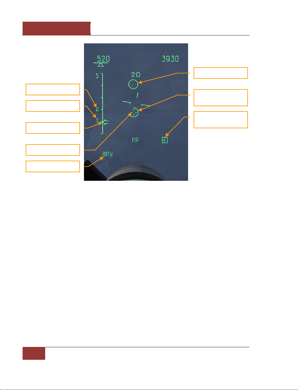
DCS
[SU-27]
64
COCKPIT INSTRUMENTS
Figure 60: Lead Computed Opitcal Sight (LCOS) mode
• The aiming crosshair appears when the target range is less than 1200 meters.
• The gun employment range scale indicates target range from 0 to 1200 meters.
• Target range is also displayed on the vertical range scale on the left side of the HUD. The
scale is set for 5 km.
• The remaining ammunition quantity displays the remaining ammunition in quarters, from 4
to 1.
For effective fire, place the aiming crosshair over the target marker and open fire by pressing the
[Space] key.
If the targeting sensors are malfunctioning or disabled, the Gun Funnel mode can be used for aimed
cannon fire.
Target lock (attack cue)
IRST active
Target range
Aiming crosshair
Target marker
Gun employment range
scale
Remaining ammunition
quantity in quarters
Combat mode (GUN)
Page 71
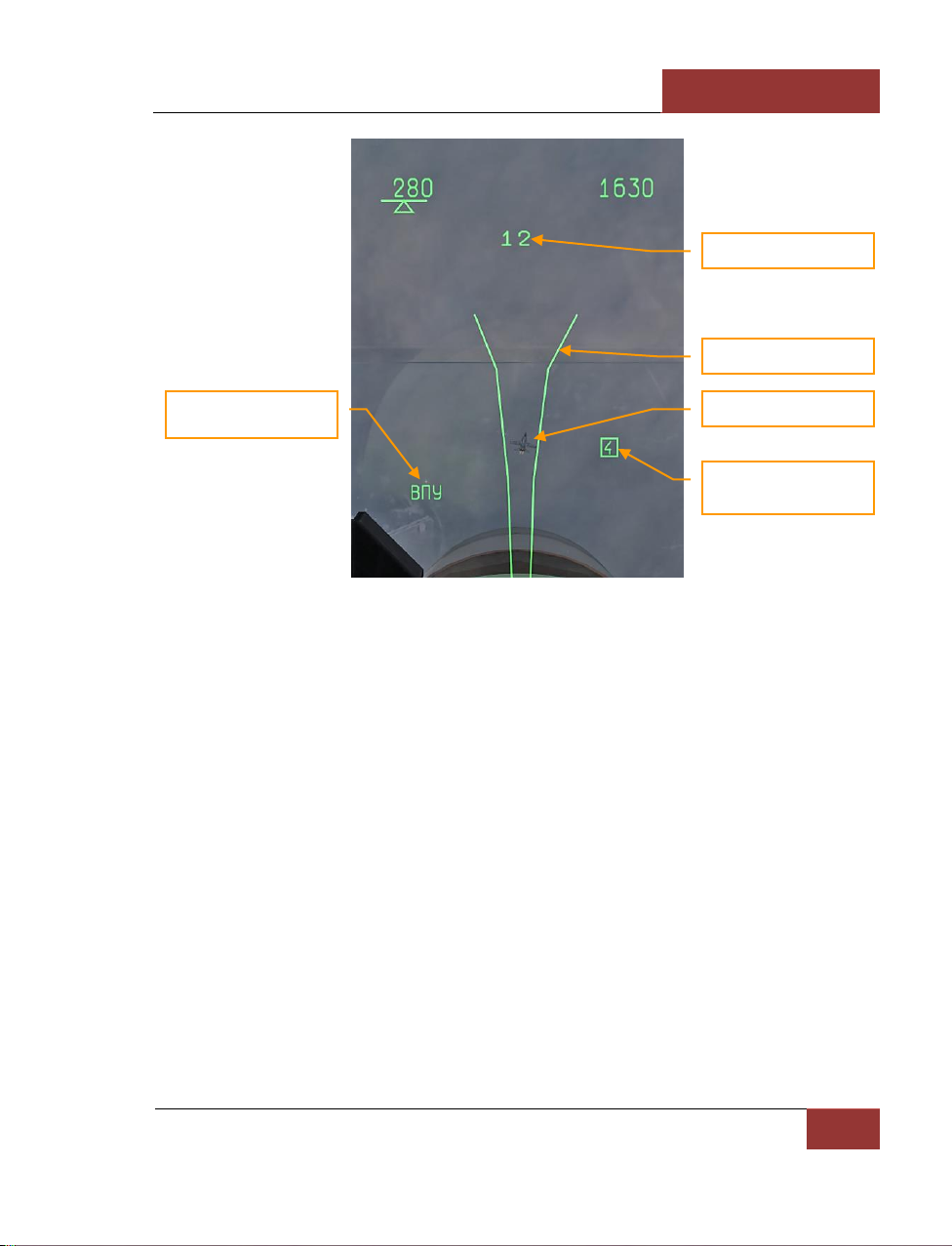
[SU-27]
DCS
Eagle Dynamics
65
Figure 61: Gun Funnel mode
In Gun Funnel mode, a graphic funnel is displayed on the HUD to indicate the calculated flight path
of cannon rounds. The distance between the sides of the funnel is based on the Target Size setting.
Target Size is an approximated value of the target’s wingspan. The Target Size value can be adjusted
using the [RAlt--], [RAlt-+] keys. The default Target Size value is 20 meters.
For effective fire using the funnel, maneuver the aircraft to place the funnel over the target so that
the target’s wingtips contact the sides of the funnel. If the Target Size is set accurately to correspond
to the target’s wingspan, you will have a good firing solution. Fire accuracy is greatest if the target’s
plain of motion is matched, e.g. if the target is turning with 30-degrees of bank, you should match
the turn with equal bank from behind the target. The gun funnel can only be employed from the rear
hemisphere.
Air-to-Ground Mode
The Su-27 can carry a limited variety of air-to-ground weapons. This includes unguided "iron" bombs
and rockets (RKT).
The GROUND mode [7] is used with these weapons. Air-to-ground aiming symbols are displayed in
the HUD. The mode name ОПТ ЗЕМЛЯ (VISUAL GROUND) appears in the lower left corner of the
HUD, and below it, the chosen weapon. The aiming principles are generally similar for all weapons –
it’s necessary to superpose the aiming pipper over the target, and drop or launch weapons when the
LA symbol indicates that the firing criteria have been met.
GUN mode
Target
Target size
Remaining ammunition
quantity in quarters
Gun Funnel
Page 72
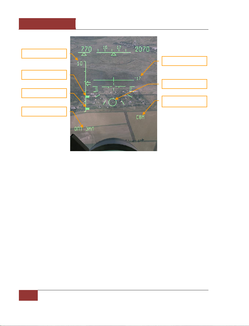
DCS
[SU-27]
66
COCKPIT INSTRUMENTS
Figure 62: VISUAL GROUND mode
• The display scale is provided in the upper left.
• Rmax and Rmin tick-marks are displayed on the range scale.
• Chosen "ОПТ ЗЕМЛЯ" (VISUAL GROUND) mode is displayed in the lower left corner of the
HUD.
• Dive (pitch) angle is displayed at the center-right of the HUD.
• Moving aiming pipper indicates the computed point of weapon impact.
Hi-drag weapons such as retarded bombs and cluster sub-munitions dispensed from containers have
a low drop trajectory which may cause the aiming pipper to remain below the lower limit of the HUD
even in a diving attack. In this case it’s better to use the continuously computed release point
(CCRP) bombing mode. This mode is described in detail in the "Weapon usage" section.
Reticle
The fixed reticle is not a combat mode, but rather a calibrated image that can be displayed on the
HUD by pressing the [8] key. The fighter WCS remains in the same mode as before [8] was
pressed, but the HUD indications are replaced by the fixed reticle.
The reticle is also a backup instrument for aiming in case of WCS failure or damage.
Range scale
Rmax
Rmin
GROUND mode
Dive angle
Aiming pipper
Selected weapon
Page 73
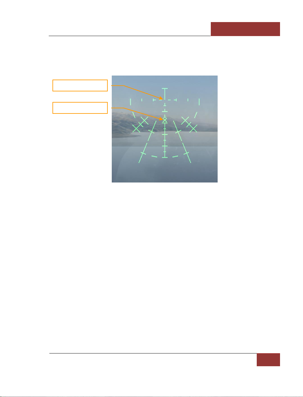
[SU-27]
DCS
Eagle Dynamics
67
The reticle displayed on the HUD is an analog to a simple collimator sight. Lead aiming and
computing is accomplished with the help of the reticle markings or "by eye".
The reticle central crosshair is aligned with the gun axis. Missile seekers aimed in Fi0 mode are
aligned somewhat lower below the central crosshair, at the position of the "X" aiming mark.
Figure 63: Reticle
Central crosshairs
Missile seeker
Page 74

DCS
[SU-27]
68
COCKPIT INSTRUMENTS
Electronic Countermeasures
Electronic warfare (EW) is a deep and complex topic that covers a long history of opposing and
rapidly evolving sensors, tactics, weapons and other equipment from numerous countries. In this
section, we consider only a few active radar jamming electronic countermeasures (ECM) - or as it has
been more recently called, "electronic attack" (EA) - systems that are designed to protect the aircraft
on which they are installed.
Electronic Countermeasures (ECM) Stations of Su-27
The Flanker's SPS-171 "Sorbtsiya" active ECM station is an analogue of the American AN/ALQ-135
station employed by the F-15C. The system is carried in two wingtip pods that replace a pair of R-73
missile pylons, thus decreasing the maximum missile carriage of the Su-27 by 2. In normal usage,
one pod acts as a receiver and the other as a transmitter, so that enemy radar signals can be
continuously analyzed, manipulated and retransmitted with distortions, even if the threat radar
frequency or bearing are changed. It employs steerable-beam antennas to organize jamming by
sector and frequency band, and has several advanced operating modes, significantly decreasing the
tracking and lock range of hostile radars.
Figure 64: SPS-171 Sorbtsiya pad
When the player-flown aircraft is equipped with such an ECM system (internally, or carried on a
weapon station as a pod), it can be toggled on and off during a mission by pressing the [E] key. The
lamp on the right panel will flash during activation of the ECM system (about 15 sec) and steady light
when the system is fully active.
Page 75

[SU-27]
DCS
Eagle Dynamics
69
Figure 65: ECM lamp
The active jammer will then work to reduce the tracking range of enemy radars and degrade the
performance of incoming radar-guided missiles. The player's use of such active ECM may come at a
price, however. The ECM may interfere with the player's own radar-guided missiles during or after
launch, hostile radars experiencing reduced tracking range may nevertheless enjoy increased
detection range, and hostile missiles may see active ECM as a beacon, and pursue it in a secondary
"Home On Jam" (HOJ) mode. For the best defense against missiles, active ECM is best combined
together with passive jamming (chaff) and perpendicular ("beaming") maneuvers at low altitude.
ECM lamp
Page 76

DCS
[SU-27]
70
SU-27 WEAPONS
SU-27 WEAPONS
Page 77
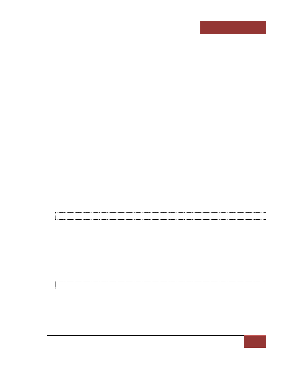
[SU-27]
DCS
Eagle Dynamics
71
SU-27 WEAPONS
The Su-27 is armed with a single 30 mm Gryazev-Shipunov GSh-30-1 cannon in the starboard
wingroot, and has up to 10 hardpoints for missiles, bombs and rockets. Its standard air-to-air combat
armament is a mixture of R-27 (AA-10 'Alamo') and R-73 (AA-11 Archer) missiles. The Su-27S can
also be armed with bombs and unguided rockets to fulfil a secondary ground attack role.
Air-To-Air Missiles
All modern fighters, and most attack aircraft, are equipped with air-to-air missiles (AAM). Though
possessing significant advantages over cannons, they have many operational limitations. For the
successful launch of any missile, one has to strictly follow defined sequences. There are unique, prelaunch steps for each type of a missile.
AAMs are a collection of integrated components that consist of the seeker, the warhead, and the
motor. Motor burn can only last for a limited amount of time. This usually ranges from 2 to 15
seconds, depending on the missile type.
At launch, the missile accelerates to its maximum flight speed. After the motor is depleted, the
missile consumes the energy acquired in the acceleration. The higher the initial airspeed at the
moment of the missile launch, the greater the airspeed of the missile and the longer its launch range
will be. An increase in launch aircraft speed corresponds to a longer missile range.
The missile launch range, or missile employment zone (MEZ), is greatly influenced by the aircraft’s
altitude at the moment of missile launch. This is due to the much denser air at lower altitude. If the
flight altitude is increased by 20,000 feet, the maximum launch range is about doubled.
TO INCREASE A MISSILE’S MAXIMUM LAUNCH RANGE, YOU SHOULD LAUNCH FROM HIGH ALTITUDES AND SPEED
Target aspect angle can also greatly influences a missile’s MEZ. The launch range increases when you
and the target are flying towards each other. This is termed a high aspect engagement. When you
attempt to attack a target from behind, the target is flying away from you and greatly reduces a
missile’s MEZ. This is termed a low aspect engagement. To increase the range of your attacks,
attempt high aspect intercepts.
Missiles fly according to the same physical laws as aircraft. When maneuvering, the missile consumes
energy when it pulls G. A maneuvering target can make the missile make significant course
corrections and thereby consume the missile’s energy. This can lead to the missile being incapable of
continuing the intercept.
AT LONG RANGES. SLOW MANEUVERING TARGETS ARE MORE EASILY HIT.
Air-to-air missiles are intended to destroy aircraft. They are divided into several classes, according to
their range and guidance principles. According to the range:
• Short range missiles. Less than 15 km. (R-73, R-60, AIM-9 and others)
Page 78

DCS
[SU-27]
72
SU-27 WEAPONS
• Medium range missiles. From 15 km up to 75 km. (R-27, R-77, AIM-7, AIM-120, and
others)
• Long range missiles. Over 75 km. (R-33, AIM-54, and others)
These missiles use a variety of guidance systems:
• Passive infrared. Infrared target seeker (R-60, R-73, R-27Т, AIM-9, R550)
• Passive radar. Radar emitter targeting, is usually combined with semi-active or active
targeting. It is a targeting mode modern missiles such as AIM-7M, AIM-120, and R-27R can
use. This is sometimes referred to as Home On Jam (HOJ) mode.
• Semi-Active Radar Homing (SARH). Such seekers home in on the reflected radar energy
from the launch aircraft’s continuous wave radar. (R-27R/ER, AIM-7, R-33)
• Active Radar Homing (ARH). Active systems have their own radar seekers built into the
missile. (R-77, AIM-120, AIM-54)
Medium and long range missiles are often fitted with an inertial navigation systems (INS) and a
command-guidance transmitter/receiver (data link). This enables such systems to be launched
towards a target’s position that is further than the supporting radar can lock and illuminate.
Passive radar and infrared homing systems do not radiate an active signal. Instead, they guide to
the target by locking on to the target’s radar or infrared emissions. These are "fire-and-forget"
missiles, i.e. they are fully automated after launch.
Semi-active missiles home in on the reflected radar energy of a target. For such missiles, it is
necessary that the supporting aircraft retain radar lock until the missile hits the target. This can
often lead to "jousting" of SARH armed aircraft.
Active missiles at long ranges have the same features as semi-active systems; i. e. the launch aircraft
must track the target and provide guidance to the missile. Once the missile is within 10 to 20 km of
the target, the onboard radar seeker activates and continues the intercept without need of support
from the launch aircraft’s radar. Such systems have only recently been introduced into service.
AAMs fly according to the same aerodynamics laws as aircraft. They are affected by the same
gravitational and drag force that affect aircraft. For a missile to fly, it must also generate lift forces.
Due to the small size of AAM wings though, lift is generally generated by speed rather than wing
form.
After launch, the missile is accelerated by its motor. This is generally a solid propellant motor that
operates from 2 to 15 seconds. During this period, the missile accelerates up to Mach 2 -3 and then
continues flight based on the stored kinetic energy to overcome drag and gravity. As airspeed
decreases, it becomes increasingly difficult for the missile to maneuver due to the decreased
efficiency of its control surfaces. When the missile’s speed falls below 1,000 – 800 km/h, it becomes
almost uncontrollable and will continue to fly ballisticly until it hits the ground or self destructs.
Maximum missile launch range is not a constant value; it depends on a number of variables:
launcher's flight altitude, air speed and target aspect. To attain a missile’s maximum launch range, it
is best to launch at high altitude, at high airspeed, in a high aspect intercept. Note that launch range
does not necessarily equate to missile flight range. For example, in a high aspect encounter where
the missile is launched at 50 km, the missile will only travel about 30-35 km. This is because the
Page 79

[SU-27]
DCS
Eagle Dynamics
73
target is flying towards the missile. Near ground level where the air density is very high, the launch
range is more than halved.
When attacking an enemy from the rear, the launch range significantly decreases because the missile
has to catch up with a target that is flying away. Rear hemisphere, low aspect, launch ranges are
usually two to three times less than high aspect launch ranges. For example, these are the launch
ranges of the R-27ER at different aspects and altitudes:
• Maximum forward hemisphere launch range at the altitude of 10 000 m. – 66 km.
• Maximum forward hemisphere launch range at the altitude of 1000 m. – 28 km.
• Maximum rear hemisphere launch range at the altitude of 1000 m. – 10 km.
Maximum launch range is calculated with the assumption that the target will not take any maneuvers
after missile launch. If the target begins to maneuver, the missile will also need to maneuver and
quickly lose energy. This is why it is more practical to use a different gauge of maximum range –
maximum launch range that takes into account target maneuverability (Rpi in western terminology).
The weapon control system constantly calculates the maximum launch range to a non-maneuvering
target, as well as the Rpi. Rpi is at a much shorter range than the maximum launch range but
ensures a much higher probability of kill. In game, these ranges are indicated on the HUD and
HDD/VSD.
Su-27 Missiles
R-27 (AA-10) Medium Range Missiles
The R-27 medium range missile family is intended for the interception and destruction of all types of
aircraft, helicopters, unmanned aerial vehicles (UAV) and cruise missiles. The missiles can be
employed in medium and long range air combat independently or as part of a group of aircraft at day
or night. The R-27 is effective in all meteorological conditions and is very capable against low flying
and maneuvering targets.
The R-27 is manufactured in several variants that differ according to their seekers – semi-active radar
or infrared – and two types of propulsion systems – standard and extended. The variants with the
semi-active radar homing seeker are termed the R-27R and the R-27ER. Variants with the infrared
seeker are termed the R-27T and R-27ET. Both the R-27ER and R-27ET have the extended, longerburning motors.
The primary material of the missile body is a titanium alloy, and the engine body is made mostly of
steel.
The same rail and ejector launchers are used for both size variants of the R-27, the standard and
extended range. The APU-470 rail launcher is intended for missiles loaded under the wings and the
AKU-470 catapult device is used for missiles loaded underneath the fuselage or wings.
In addition to the seekers, the missile control system also includes an inertial navigation system with
radio correction. The all-aspect R-27 attacks the target at its any initial position within a 50 degree
gimbal limit for the semi-active radar seeker and 55 degrees for infrared. Maximum aircraft G loading
at the launch can be up to five units. The R-27 can intercept targets flying at speeds up to 3500
Page 80
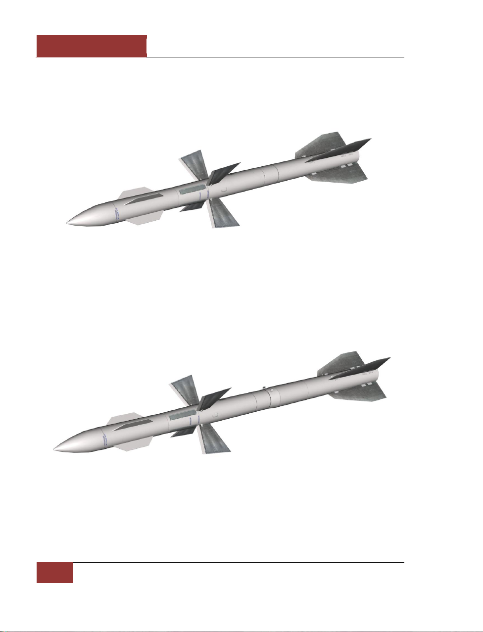
DCS
[SU-27]
74
SU-27 WEAPONS
km/h and altitudes from 20 m to 27 km. Maximum target and launch aircraft altitude difference can
be up to 10 km. Maximum target G is eight. The combined launch of R-27 missiles with different
seeker variants increases the resistance to target counter measures. The R-27 family of missiles was
developed by the Vympel design bureau and went into operational service between 1987 and 1990.
Today, all versions of the MiG-29 and Su-27 fighters are equipped with these missiles.
Figure 66: R-27R missile
R-27R. "Product 470R" (AA-10А Alamo) is a radar-guided, medium-range "air-to-air" missile that
went into operational service in 1987. The missile has inertial navigation guidance system with radio
correction. For terminal guidance, the R-27R has a semi-active radar seeker. The maximum launch
range is 30-35 km. The maximum target speed is 3600 km/h, the maximum target G is eight, and the
initial weight of the R-27R is 253 kg. It has a length of 4 m, a maximum body diameter of 0.23 m,
and a wing span of 0.77 m. The cruciform control surfaces span 0.97 m and the expanding rod
warhead weighs 39 kg.
Figure 67: R-27ER missile
R-27ER. "Product 470ER" (AA-10C Alamo) is a radar-guided, medium-range missile that is a
modification of the R-27R with a larger motor. The missile has inertial navigation guidance system
with radio correction. For terminal guidance, the R-27ER has a semi-active radar seeker. The
maximum, effective launch range is 66 km. The maximum target altitude is 27 km. The R-27ER’s
initial weight is 350 kg; the length is 4.78 m; the maximum body diameter is 0.26 m; and the wing
Page 81
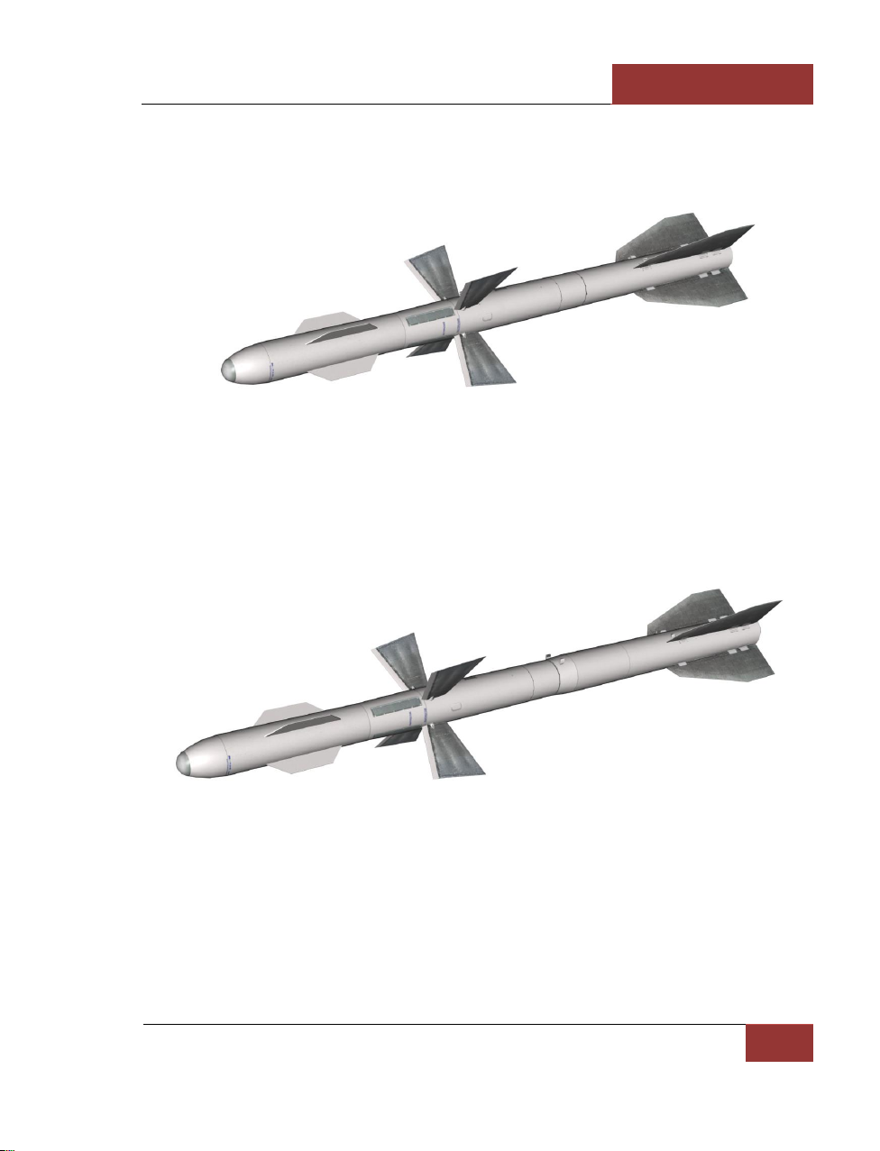
[SU-27]
DCS
Eagle Dynamics
75
span is 0.8 m. The control surfaces span 0.97 m. The expanding-rod warhead weighs 39 kg. The Su27 and its variants can be equipped with this missile.
Figure 68: R-27T missile
R-27T. "Product 470Т" (AA-10B Alamo) is a medium range "air-to-air" missile and became operational
in 1983. This version of the R-27 uses an infrared seeker. The R-27T must have infrared seeker lock
on the target before launch. The maximum, effective launch range is 30 km and can engage targets
up to 24 km in altitude. The launching weight is 254 kg; missile length is 3.7 m; and maximum body
diameter is 0.23 m. The wing span is 0.8 m. The expanding-rod warhead weighs 39 kg. Su-27, MiG29 and their variants can be equipped with this missile.
Figure 69: R-27ET missile
R-27ET. "Product 470ET" (AA-10D Alamo) is a medium range "air-to-air" missile and became
operational in 1990. This version of the R-27 uses an infrared seeker. The R-27T must have infrared
seeker lock on the target before launch. Like the R-27ER, the R-27ET also has a larger motor that
provides it greater range. The maximum launch range is 60 km (on the condition of the target lock
on with the infrared seeker). The maximum target altitude is 27 km. The R-27ET’s weight is 343 kg.
The missile’s length is 4.5 m. The maximum body diameter is 0.26 m. The wing span is 0.8 m. The
expanding-rod warhead weighs 39 kg. The Su-27 and its variants can be equipped with this missile.
Page 82
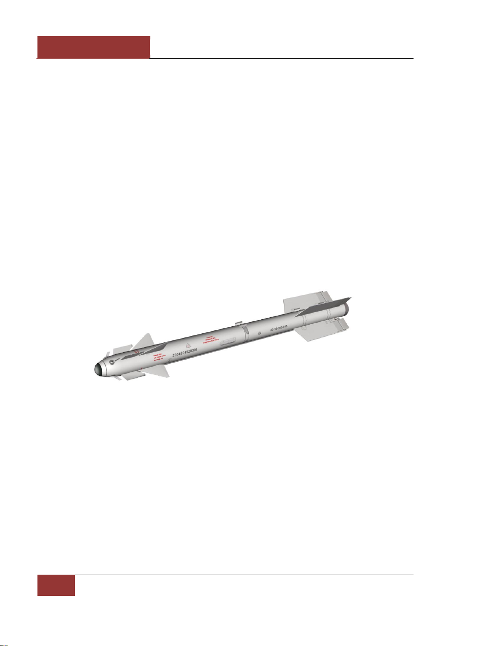
DCS
[SU-27]
76
SU-27 WEAPONS
R-73 (AA-11) Short Range Missile
Following poor combat results in Vietnam at the end of the 1960s, the United States began
developing its fourth generation fighters, the F-14 and F-15. Like the F-16 and F/A-18 light fighters,
these aircraft were intended gain air superiority; this would include close range air combat. At the
beginning of the 1970s in the USSR, a sort of "symmetrical answer" to the western countries resulted
in the design of new front line fighters, later called the Su-27 and MiG-29.
Estimated requirements for a new missile to arm the new generation of Soviet fighters, showed that
even a specially enhanced version of the R-60M (its development was coming to an end in those
years) would not fully satisfy the new requirements. According to the analysis, missiles of the new
generation were to be highly maneuverable and have all-aspect engagement capabilities.
At first, these requirements were distributed between two different design bureaus. Reviewing the
results and preliminary developmental work performed in the framework of the avanproject, a
resolution dated July 26, 1974 defined the requirements of the future Su-27 and MiG-29, entrusted
"Molniya" design bureau with development of a highly-maneuverable, small, close air combat missile
- the K-73. The missile was first envisioned as an enhanced P-60, but taking into account the high
maneuverability requirements, it was allowed to increase its weight to be between the R-60 and R-
13.
Figure 70: R-73 missile
The same day, another resolution entrusted "Vympel" design bureau with development of an allaspect short-range missile. This K-14 was a further development of K-13 family and included an
infrared seeker and superb aerodynamic performance.
The "Super-maneuverability" requirements defined the necessity of K-73 operations at extremely high
angles-of-attack (about 40°). At such angles, the efficiency of traditional A-A missile control surfaces
are completely lost. A transition to gas-dynamics control units in such conditions was inevitable. Wing
surfaces changes was also considered inefficient with regard to a relatively short launching range.
Given the assumption of the first K-73 variant’s small size and weight, an all-aspect seeker was not
envisioned. Nevertheless, at Kiev "Arsenal" design bureau, which earlier worked with the Moscow
"Geophisica" design bureau, developed a rather compact seeker "Mayak" (OGS MK-80) with a new
seeker. The new seeker provided target acquisition up to 60°, which was 12 times greater that the
corresponding seeker for the R-60. Later, the K-73 gimbal limits were increased to 75° with a
Page 83
[SU-27]
DCS
Eagle Dynamics
77
maximum angle speed of up to 60 degrees per second. "Mayak" seeker also included new, efficient
anti-countermeasures (flares) implemented. In addition to an increased sensitivity range for the
photo-detector array, a pulse-time signal modulation was applied, and a digital signal processing unit
with several independent channels was introduced. To increase engagement efficiency, the steering
point logic was adjusted to aim for a point forward of the targets engine nozzles. This allowed the
warhead to damage more critical parts of the aircraft system, such as the pilot.
Despite the formal absence of an all-aspect engagement requirement, K-73 developers pursued the
"Mayak" seeker because it was evident that sooner or later this requirement would be demanded.
Providing these capabilities required that the K-73 size and weight increase.
The initial, wingless design had limited maneuverability. High angle of attack is generally required
when dog fighting, and this is generally not favorable for such a design. For a time, the designers
considered a missile variant without aerodynamic control surfaces but instead use six, large sixcantilevers.
However, the use of gas-only control units limited the flight time by motor operation time. This
significantly decreased tactical employment flexibility. When reviewed at a headed by G.Dementiev, it
was decided to adopt a aerodynamic design similar to that of the K-60. However, unlike the
prototype, they had to provide bank stabilization when the missile was equipped with an autopilot
with traditional gyroscopes. Use of kinematically connected ailerons rather than rollerons was not
accompanied by a missile weight increase. This was because earlier variants had surfaces actuators
elements for gas-dynamic control units operation in the tail section. For control routines, the
autopilot used information from the angles-of-attack and sideslip sensors that are positioned in front
of destabilizes. Like the P-60, this also ensured air flow straightening before the aerodynamic control
surfaces.
A set of sensors, destablators and control surfaces form the characteristic "pine cone" on the first
missile section. Aerodynamic control surfaces, along with a pair of aerodynamic connectors, are used
by the steering motors in the forward part of the second section. This is located behind the autopilot
and active radio proximity fuse. The third section is occupied by a solid propellant gas generator. The
produced actuating fluid is sent to the actuators of aerodynamic controls and through the gas
pipeline coming through the fairing. This in turn actuates the ailerons and exhaust vanes positioned
in the missile’s tail section. The fourth section contains an expanding-rod warhead; inside the
warhead is a safety-and-fusing device. The warhead blast radius is about 3.5 m. The fifth section is a
single-mode solid propellant motor. In the missile’s tail section are the actuators of the ailerons and
gas-dynamic vanes.
Except for the steel engine body, most of the airframe is made of aluminum alloys. The sections are
joined by bayonet joints, except for the end sections that are connected by flange joints. The fully
assembled missile is delivered in a hermetically sealed in a wooden packing crate. The missile is
suspended from the aircraft by the P-72 or P-72D launchers (APU-73-1 or APU-73-1D).
As a result of the joining of two "air-to-air" missile design teams, the K-73 development was
completed at "Vympel" design bureau. The missile went into operational service as the R-73 by
Resolution June 22, 1984. The maximum launch range of the R-73 is 30 km in the forward
hemisphere and high altitude. On the whole, missile’s performance characteristics exceeded the initial
goals, but at the same time the missile’s weight was 1.5 the initial design specification.
The R-73 was exported abroad as the K-73E variant; the first deliveries were made to East Germany
in 1988. The missile was named АА-11 Archer in western terminology. The R-73, when combined
with helmet mounted cueing device "Shel-3UM", enables a pilot to achieve air superiority in close air
Page 84

DCS
[SU-27]
78
SU-27 WEAPONS
combat. This was confirmed during initial joint trainings of the former Warsaw Pact countries (in
particular, East Germany) with NATO pilots who flew some of the best western fighters.
In the 1990s, "Vympel", in the course of international exhibitions, displayed various enhancements of
the of R-73, In particular, photos of attack aircraft using a backwards launching version that could
attack threats approaching from the rear hemisphere were shown.
The launch range of the R-73 is between 0.3 and 20 km and engage targets as high as 20 km. The
initial weight is 105 kg. The missile length is 2.9 m. and the maximum body diameter is 0.17 m. The
wing span is 0.51 m. The control surfaces span .0.38 m. Maximum speed of the target is 2500 km/h.
The warhead weight is 7.4 kg. The maximum target G is 12 units. MiG-29, Su-27 and their variants
are equipped with this missile system.
The table below compares the characteristics of R-27 missiles family.
Parameters
R-27R/T
R-27ER/ET
The year it entered service
1987
1990
Aircraft/number carried
MiG-29/4; MiG-29SMT/4; Su-27/4; Su-35 /4; Su-34/4; Su-33/6
Weapon control system
SUV S-29; SUV S-29M; SUV S-27; SUV S-27M
Aerodynamic design
Canard with destabilizers
Weight, kg
253
354
Warhead weight, kg
39
Warhead type
Rod-type
Body diameter, m
0,23
0,23/0,26
Length, m
3,96
4,56
Control surface span, m
0,77
0,8
T/W ratio, Kgs/Kg
62
94
Motor type
single-mode
double-mode
Seeker gimbal limits
±50° for radar TSD;
±55° for IR TSD
Guidance system type
Inertial guidance with radio correction; self-guidance with semiactive TSD with lock-on after launch; infrared TSD cooled by
nitrogen
Guidance method
Proportional guidance
Target maximum speed,
km/h
3500
Target maximum range, km
0,03 - 25
0,03 - 27
Page 85
[SU-27]
DCS
Eagle Dynamics
79
Maximum launch range in
forward/rear hemisphere,
km
45/18
70/30
Minimum launch range in
rear hemisphere, km
0,5
Maximum target G, units
8
Page 86

DCS
[SU-27]
80
SU-27 WEAPONS
Air-To Surface Weapons
Air-to-Surface weapons can be divided into two categories: guided and unguided. Guided air-tosurface weapons include both powered air-to-surface missiles (AGMs and ASMs) and guided bombs
(GBUs). Unguided weapons include free-fall ("dumb" or "iron") bombs and unguided aerial rockets.
Originally Su-27 can use only unguided bombs and rockets.
Free-fall bombs are basic weapons of strike aviation that have been widely used in all the large-scale
armed conflicts of the last 80 years. Due to their low cost and availability, they can often be costeffective even when compared to more accurate (and expensive) modern guided munitions.
Free-fall bombs are not highly accurate. They follow a ballistic trajectory after release without any
ability to maneuver. To improve aiming accuracy, the bombing aircraft should be flying a straight-line
trajectory at the moment of release. Even small amounts of pitch and bank error can degrade the
aiming accuracy, as can the wind. Free-fall bombs can't be used against pinpoint targets (i.e. when
high aiming accuracy is required) or "surgical strikes" in which "collateral damage" around the vicinity
of the target cannot be tolerated.
EVEN INCORRECT AIRCRAFT YAW AT THE MOMENT OF RELEASE CAN DEGRADE THE HIT ACCURACY OF FREE-FALL
BOMBS.
The horizontal distance that a free-falling bomb will travel before hitting the ground depends
primarily on two factors: aircraft speed and altitude at the moment of release. If the aircraft speed
and altitude are increased, the bomb trajectory will be extended, but this also degrades hit accuracy.
The size and destructive power of a conventional free-fall bomb is expressed in terms of its weight,
and is usually somewhere between 50 to 1500 kg. Unlike general-purpose bombs, which have a
single warhead, cluster bombs contain a large number of explosive sub-munitions that spread their
destructive power out over a larger area after release.
THE RANGE OF FREE-FALL BOMBS DEPENDS ON THE AIRCRAFT SPEED AND ALTITUDE AT THE MOMENT OF
RELEASE.
Unguided folding-fin aerial rockets are widely employed against lightly armored enemy vehicles and
personnel. A rocket's hit accuracy depends heavily on the conditions at the moment of launch. A
small aircraft aiming error at the moment of launch can lead to a significant rocket deviation from the
target. Wind can also degrade the hit accuracy. Rockets are usually used in volleys, en masse. Using
a large number of rockets can spread destructive power over a significant area, and help ensure
hitting the intended target.
UNGUIDED ROCKETS ARE LAUNCHED IN SALVOS TO ENSURE HITTING THE TARGET.
Free-fall Bombs
Su-27 has some limited ground attack capability, being able to carry free-fall bombs and unguided
rockets in place of air-to-air missiles.
Free-fall bombs lack any guidance or control system. They follow a ballistic trajectory that is affected
by the releasing aircraft's speed and dive angle.
Page 87
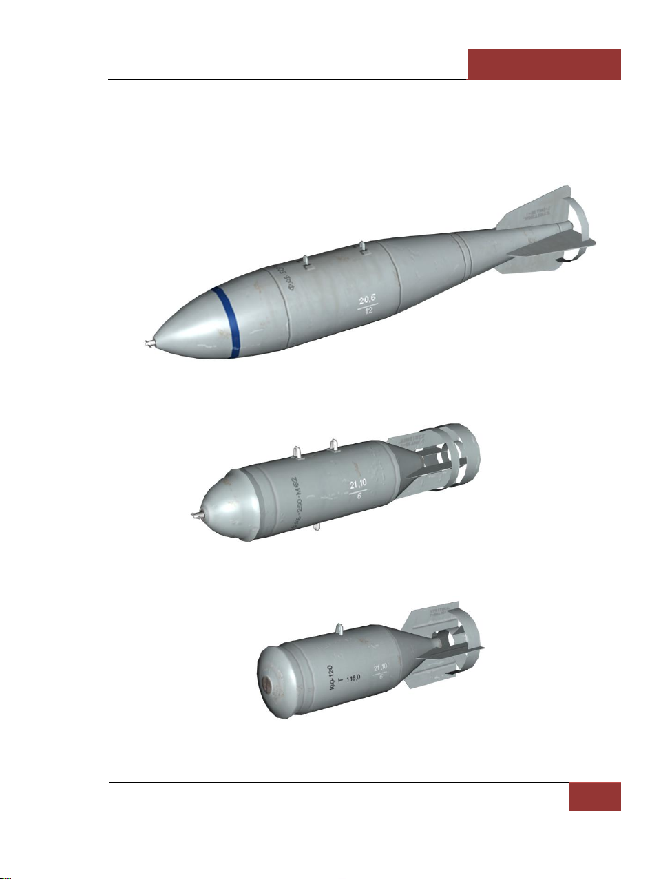
[SU-27]
DCS
Eagle Dynamics
81
FAB-100, FAB-250, FAB-500, FAB-1500 - General Purpose Bombs
This is a family of high-explosive bombs of varying caliber. The number in the designation refers to
the bomb's approximate weight (in kilograms). These bombs are effective against ground objects,
equipment, defensive installations, bridges and fortifications. The airspeed at the moment of bomb
release may be 500 – 1000 km/h.
Figure 71: FAB-500 High-Explosive Bomb
Figure 72: FAB-250 High-Explosive Bomb
Figure 73: FAB-100 High-Explosive Bomb
Page 88
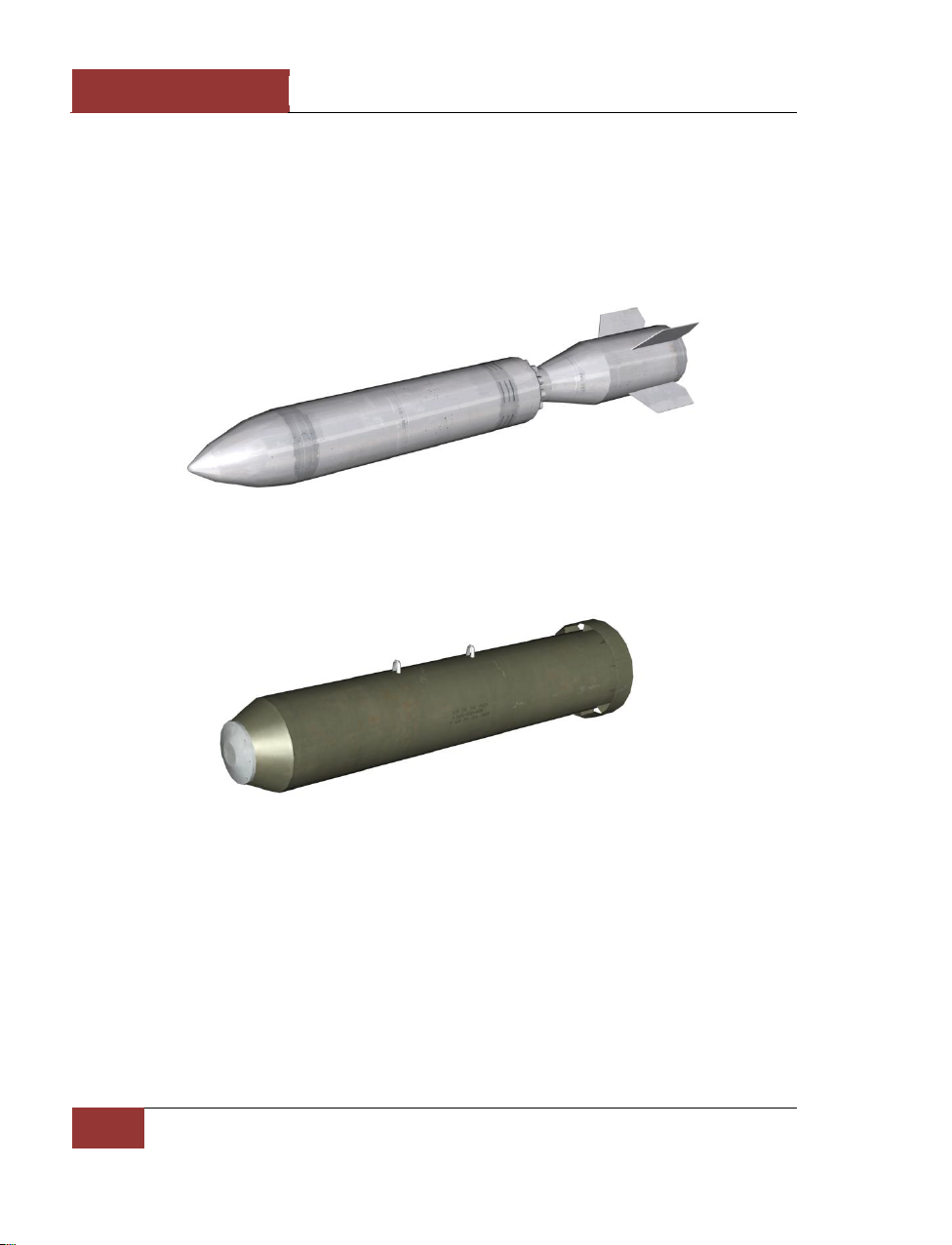
DCS
[SU-27]
82
SU-27 WEAPONS
BetAB-500ShP Concrete Piercing Bomb
This special bomb is effective against hardened shelters and concrete runways. It has a parachute
and solid propellant rocket motor. First the parachute retards the bomb, giving the aircraft time to
egress, and orients the bomb vertically over the target. Then the rocket motor ignites, accelerating
the warhead to a speed sufficient to pierce concrete. The bomb has a stronger casing than ordinary
high explosive bombs that allows it to be buried into the concrete before detonation. This bomb is
best dropped from an altitude of 150 – 1000 meters and airspeed 550 to 1100 km/h.
Figure 74: BetAB-500ShP Concrete Piercing Bomb
SAB-100 Illumination Bomb
Figure 75: SAB-100 Illumination Bomb
This 100 kg-caliber flare-bomb is used to illuminate a target area after dark. The dispensing container
is released from an altitude of 1000 – 3000 m, after which illuminating flares are ejected in sequence.
Each flare element is equipped with a parachute to decrease the rate of fall. The illumination time
lasts 1 – 5 minutes.
RBK-250, RBK-500 Cluster Bomb
RBK cluster bombs are thin-walled canisters that contain multiple antipersonnel or antitank mine, or
fragmentation, antitank or incendiary bomblet sub-munitions. The cluster bomb has about the same
dimensions as a general purpose high explosive bomb with caliber 100 – 500 kg and are designated
Page 89
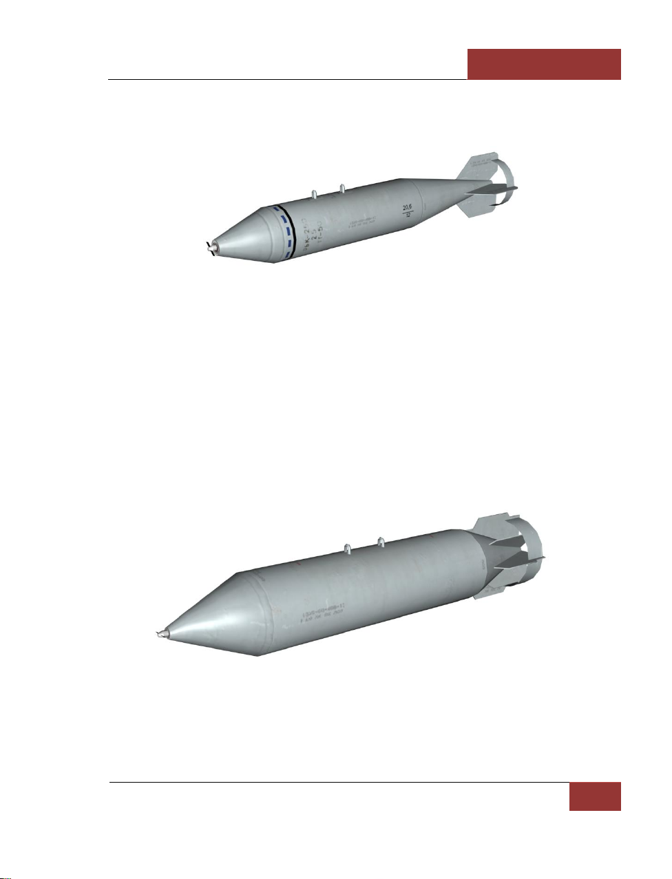
[SU-27]
DCS
Eagle Dynamics
83
according to caliber and ammunition type (e.g. RBK-250 AO-1 for a 250 kg antipersonnel bomb). The
different RBK types are also distinguished from each other by the method of dispersing submunitions.
Figure 76: RBK-250 Cluster Bomb
The nose of the canister contains a black gunpowder dispersal charge triggered by a time-delay
screw fuse. The time-delay fuse starts spinning after bomb release and the cluster bomblets are then
ejected in mid-air. The expanding gases split the canister casing in two, scattering the independent
bomblets. The area over which sub-munitions are distributed is called the bomb's footprint.
Depending on the bomb's fall angle at the moment of sub-munitions dispersal, the footprint may be
circular or elliptical, and its dimensions determined by the canister speed and altitude. The canister
may also feature internal mechanisms to increase the footprint area of bomblet dispersal by ejecting
them with a greater speed or time interval.
There are several types of RBK cluster bomb.
The RBK-250 AO-1 is equipped with 150 fragmentation bomblets. Canister length is 2120 mm,
diameter 325 mm, weight 273 kg, including 150 kg of sub-munitions. The maximum footprint area is
4,800 m2.
Figure 77: RBK-500 Cluster Bomb
The RBK-500 AO-2.5RTM bomb is equipped with 108 AO-2.5RTM bomblets. Canister length is 2500
mm, diameter 450 mm, weight 504 kg, including 270 kg of sub-munitions. A single AO-2.5RTM submunition (bomblet) weighs 2.5 kg, with 150 mm length and 90 mm diameter. RBK-500 AO-2.5RTM
Page 90
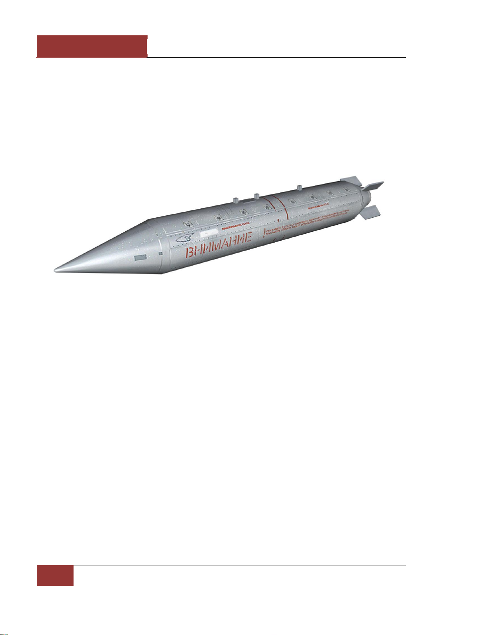
DCS
[SU-27]
84
SU-27 WEAPONS
cluster bombs are dropped from an airspeed of 500 to 2300 km/h and altitudes between 300 m to 10
km.
KMGU-2 Submunition Dispenser
The KMGU-2 ("General Container for Small-Sized sub-munitions") is designed to dispense small
caliber bomblets and air deployed mines. The sub-munitions are placed in the dispenser in cartridges
(BKF – "container blocks for frontal aviation"). The KMGU-2 consists of a cylindrical body with front
and rear cowlings and contains 8 BKF cartridges filled with bomblets or mines, carried in specialized
slots. The dispenser doors are pneumatically actuated to dispense the sub-munitions.
Figure 78: KMGU-2 Sub-munitions Dispenser
The KMGU-2 electrical system ensures a regular time interval of 0.005, 0.2, 1.0 or 1.5 seconds
between each cartridge release. BKF cartridges carried by Su-25 aircraft are usually equipped with 12
AO-2.5RT fragmentation bombs of 2.5 kg caliber, 12 PTM-1 1.6 kg antitank mines, or 156 PFM-1C 80
g high explosive mines. KMGU-2 dispensers are suspended singly on universal BDZ-U beam bomb
racks. Cartridges are released from altitudes of 50-150 m and airspeeds of 500–900 km/h.
Authorization for release is provided by cockpit indications.
Unguided Aerial Rockets
Despite the existence of precision guided weapons, unguided rockets continue to see widespread use
as air-to-ground weapons, combining effectiveness, reliability and ease of use with low cost. The
unguided rocket has relatively simple design, consisting of a fuse, warhead, body, rocket motor and
stabilizing fins. Unguided rockets are usually carried in special containers or launch tubes. The rocket
motor usually burns for 0.7 to 1.1 s after launch, accelerating the rocket to speeds of 2100 – 2800
km/h. After motor burnout, the rocket flies a ballistic trajectory like an artillery shell. To ensure
directional stability, the rocket stabilizing fins, located at the tail, unfold from their stowed position.
Some rockets are further stabilized by gyroscopic rotation around the longitudinal axis. An aircraft
can be equipped with unguided rockets of different calibers (from 57 mm to 370 mm) and/or
warheads, depending on the mission. The fuse can be contact- or proximity-detonated to achieve the
desired dispersal of blast fragments.
Hit accuracy is dependent on the rocket's flight range, which in turn varies according to rocket type
and caliber. Error accumulates with longer ranges, since the rockets fly without any trajectory
Page 91

[SU-27]
DCS
Eagle Dynamics
85
guidance. The permissible launch zone for each type of unguided rocket is defined between its
maximum range, and the minimum safe blast distance. The minimum safe distance depends on the
warhead type and weight, and protects the firing aircraft from exploding fragments. Rockets are
usually fired at airspeeds of 600 – 1000 km/h with a dive angle of 100 – 300. The pilot maneuvers the
entire aircraft to put the aiming pipper on the target before firing.
S-8 rocket
The S-8 is a medium caliber (80 mm) unguided rocket. Twenty rockets are carried per weapon
station in B-8 multiple launchers. For improved aiming accuracy, the rocket features 6 stabilizer fins,
which are unfolded at launch by a piston driven by the rocket motor exhaust gases. The fins are then
locked in the unfolded position. The fins are held in the folded position by a covering that is
discarded at the moment of launch. The impulse and burn rate of the S-8 rocket motor was increased
with respect to the S-5 rocket, to provide the heavier S-8 with rapid acceleration and rotation; the
motor burn time was decreased to 0.69 sec. S-8 dispersion during flight and circular error probable
(CEP) is 0.3% of the range. The maximum effective launch range is 2 km.
Figure 79: B-8M1 Rocket Launcher
The S-8TsM is a smoke rocket variant, used to designate targets for friendly strike aircraft. The signal
smoke indicates the position of the target.
S-13 rocket
These 132 mm unguided rockets are carried in B-13 launchers containing 5 rockets each. They are
designed for strikes against fortified and hardened objects (pillboxes, shelters, airport aprons and
runways). The Russian Air Force also uses 122 mm "type-013" unguided rockets. The S-13 preserves
the layout of the smaller S-8 rocket (folded stabilizing fins located between the rocket nozzles with
exhaust pressure actuation), with improved ballistic characteristics and hit accuracy.
Page 92

DCS
[SU-27]
86
SU-27 WEAPONS
Figure 80: UB-13 Rocket Launcher
S-13 rockets can be fitted with different types of warheads. The rocket has the ability to penetrate up
to 3 meters of earth or 1 meter of concrete. Its effective range is 3 km. The S-13T variant has twostage action, and detonates inside the target after penetrating (up to 6 m earth or 2 m concrete). It
can create runway craters with an area of 20 sq. meters.
The S-13OF blast-fragmentation variant generates 450 fragments weighing 25–35 g each, and is
effective against unarmored targets.
All of the S-13 rocket variants are designed to be fired from aircraft speeds of 600 – 1200 km/h.
S-13 rockets are fired from B-13L 5-rocket launchers. The launcher has a length of 3558 mm and a
diameter of 410 mm. The empty launcher weight is 160 kg.
Su-17M4, Su-24, Su-25, Su-27, MiG-23, Mig-27 aircraft and Mi-8, Mi-24, Mi-28 and Ka-50 helicopters
can be equipped with S-13 rockets.
S-25 Rocket
The S-25 unguided heavy rocket was produced in two versions, one with the S-25-0 fragmentation
warhead and the other with the S-25-F high explosive warhead.
The 340 mm caliber S-25-F has a length of 3310 mm and launch weight of 480 kg. The high
explosive warhead weighs 190 kg, including 27 kg of explosive, and is equipped with a contact fuse
of varying time delay.
Page 93

[SU-27]
DCS
Eagle Dynamics
87
Figure 81: S-25 Rocket
The S-25-0 rocket has the same caliber as the S-25-F, a full length of 3307 mm and a launch mass of
381 kg. The warhead weights 150 kg and is equipped with an adjustable radio proximity fuse for
detonation at altitudes of 5 to 20 m above the ground. The warhead explodes into 10 thousand
fragments.
Figure 82: S-25 Unguided Rocket in its Launch Tube
The fins of the S-25 rocket are folded between four motor exhaust nozzles, which are slanted as on
the S-24 to impart spin to the rocket at the moment of launch. The S-25 rocket solid propellant
rocket motor consists of a mono-block high-energy fuel mixture weighing 97 kg. A smoke tracer is
provided between the exhaust nozzles for observation and photo-record of the rocket flight path.
The S-25 has an effective launch range of 4 km. At the end of 1973, development work began on a
laser-guided variant, designated the S-25L and equipped with a 2N1 laser-homing seeker, power unit,
actuators and control surfaces. This variant was carried in the PU-0-25-L launcher.
The specifications of some unguided rockets are shown in table below.
Unguided rocket
Effective range, km
Weight, kg
Warhead type
S-8ОFP
2,2
15,2
Blast-fragmentation
Page 94
DCS
[SU-27]
88
SU-27 WEAPONS
S-8TsM
2,2
15
Smoke (target designation)
S-13-OF
2,5
68/67
Blast-fragmentation
S-24B
2
235
Blast-fragmentation
S-25-OF
4
480
Blast-fragmentation
Page 95
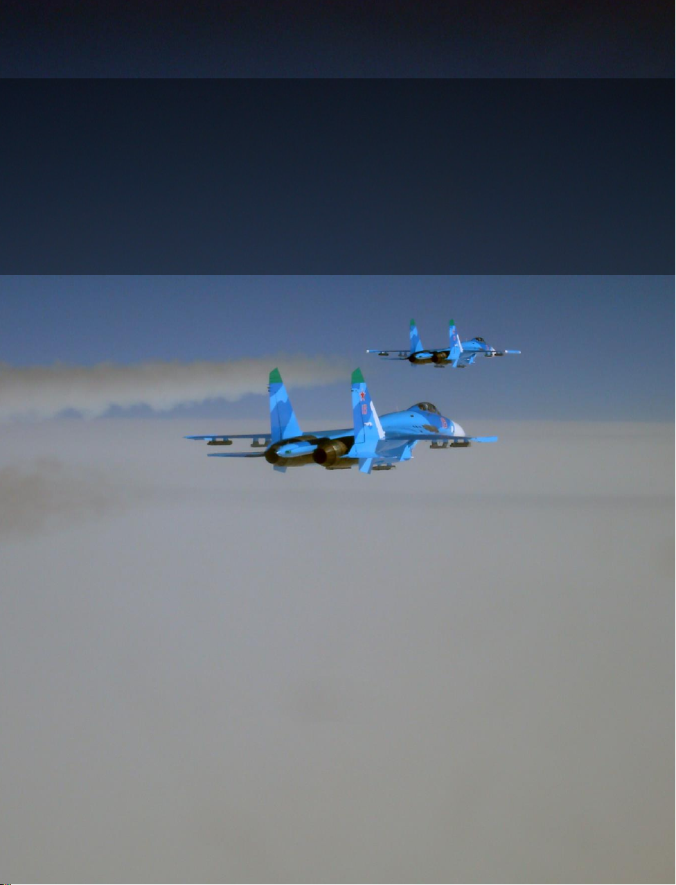
[SU-27]
DCS
Eagle Dynamics
89
RADIO
COMMUNICATIONS
RADIO
COMMUNICATIONS
Page 96
DCS
[SU-27]
90
RADIO COMMUNICATIONS AND MESSAGES
RADIO COMMUNICATIONS AND
MESSAGES
In the early days of air combat, communication between pilots was difficult, and often impossible.
Lacking radios, early pilots were basically limited to hand signals. Coordination between pilots,
especially during a dogfight, was generally impractical.
Although modern electronics have greatly improved communications capability, communications still
faces some frustrating limitations. There may be dozens, if not hundreds, of combatants using any
given radio frequency. When those people all try to talk at once in the heat of battle, the resulting
conversations generally become jumbled, cut-off, and unintelligible. Pilots, therefore, strive to adhere
to a strict radio discipline with each message, conforming to a standard Callsign, Directive,
Descriptive. The "callsign" indicates who the message is intended for and who it is from, the
"directive" contains brief instructions for the recipient, and the "descriptive" specifies additional
information. For example:
Chevy 22, Chevy 21, hard right, bandits low 4 o’clock
This message was sent by #1 of Chevy flight to #2 of "Chevy" flight. Chevy 21 has instructed Chevy
22 to execute a hard right turn. The descriptive portion of the message explains why… there are
bandits at Chevy 22’s four o’clock low position.
RADIO MESSAGES SHOULD BE BRIEF AND TO THE POINT
There are three types of radio communications in game:
• Radio commands that the player issues to other aircraft.
• Radio messages sent to the player from other aircraft, ground controllers, etc.
• Voice messages and warnings from the player’s own aircraft.
Radio Commands
The following table describes the kinds of messages that the player may send and lists the key
strokes needed to send each message. Depending on the type of command, it will take either two or
three keystrokes to issue the desired message. There are also hot keys that allow the sending of a
complex message as a single keystroke.
• Message target – This column indicates who the message is intended for, and may be the
entire flight, a specific wingman, an AWACS/GCI controller, or an air traffic controller.
• Command – The command indicates the type of message you intend to send (such as an
"Engage" command, or a "Formation" command, etc.)
Page 97
[SU-27]
DCS
Eagle Dynamics
91
Sub Command – In some cases, the sub-command specifies the exact type of command (such as
"engage my target" or "Formation, line abreast.")
As illustrated in the table below, depending on the type of command, it takes either two or three
keystrokes to generate the desired message. For example, to order the #3 wingman to engage the
player’s target, press F3, F1, F1.
Player-Generated Radio Commands
Message
Target
Command
Sub
Command
Definition of Command
Response(s) to Command
Flight or
Wingmen
Engage...
My Target
Player requests
wingmen to attack the
target that is the focus
of a sensor (radar or
EOS) or padlock. When
the target is destroyed,
wingmen will return to
formation.
If wingman is capable of carrying
out this command, he will respond
"(x) Copy," "(x) Roger," or "(x)
Affirm," where (x) is the flight
member. If wingman is incapable
of carrying out command, he will
respond, "(x) Negative," or "(x)
Unable," where (x) is the flight
member.
My Enemy
Player requests
wingmen to attack
enemy aircraft that is
attacking him.
If wingman is capable of carrying
out this command, he will respond
"(x) Copy," "(x) Roger," or "(x)
Affirm," where (x) is the flight
member. If wingman is incapable
of carrying out command, he will
respond, "(x) Negative," or "(x)
Unable," where (x) is the flight
member.
Bandits
Player requests
wingmen to leave
formation and engage
bandits (enemy
aircraft) within sensor
range. When the
target is destroyed,
wingmen will return to
formation.
If wingman is capable of carrying
out this command, he will respond
"(x) Engaging bandit," where
(x) is the flight member. If
wingman is incapable of carrying
out command, he will respond,
"(x) Negative," or "(x)
Unable," where (x) is the flight
member.
Page 98
DCS
[SU-27]
92
RADIO COMMUNICATIONS AND MESSAGES
Air
Defenses
Player requests
wingmen to leave
formation and attack
any air defense units
they detect. When the
target is destroyed,
wingmen will return to
formation.
If wingman is capable of carrying
out this command, he will respond
"(x) Attacking air defenses,"
where (x) is the flight member. If
wingman is incapable of carrying
out command, he will respond,
"(x) Negative," or "(x)
Unable," where (x) is the flight
member.
Ground
Targets
Player requests
wingmen to leave
formation and attack
enemy ground targets.
Valid ground targets
include any structure
or vehicle assigned as
enemy in the mission
editor. When the
target is destroyed,
wingmen will return to
formation.
If wingman is capable of carrying
out this command, he will respond,
"(x) Attacking target," where
(x) is the flight member. If
wingman is incapable of carrying
out command, he will respond,
"(x) Negative," or "(x)
Unable," where (x) is the flight
member.
Naval
Targets
Player requests
wingmen to leave
formation and attack
any enemy naval
target within sensor
range. When the
target is destroyed,
wingmen will return to
formation.
If wingman is capable of carrying
out this command, he will respond,
"(x) Attacking ship," where (x)
is the flight member. If wingman is
incapable of carrying out
command, he will respond, "(x)
Negative," or "(x) Unable,"
where (x) is the flight member.
Mission
and Rejoin
Player requests that
wingmen leave
formation and attack
the mission objective
as identified in the
mission editor. Once
complete, the
wingman will rejoin
formation with player.
If wingman is capable of carrying
out this command, he will respond,
"(x) Attacking primary," where
(x) is the flight member. If
wingman is incapable of carrying
out command, he will respond,
"(x) Negative," or "(x)
Unable," where (x) is the flight
member.
Page 99
[SU-27]
DCS
Eagle Dynamics
93
Mission
and RTB
Player requests that
wingmen leave
formation and attack
the mission objective
as identified in the
mission editor. Once
complete, the
wingman will return to
base.
If wingman is capable of carrying
out this command, he will respond,
"(x) Attacking primary," where
(x) is the flight member. If
wingman is incapable of carrying
out command, he will respond,
"(x) Negative," or "(x)
Unable," where (x) is the flight
member.
Flight or
Wingmen
Go to…
Return To
Base
Wingmen will leave
formation and land at
their designated
airfield. If no airfield is
designated, they will
land at the nearest
friendly airfield.
If wingman is capable of carrying
out this command, he will respond,
"(x) Copy," "(x) Roger," or "(x)
Affirm," where (x) is the flight
member. If wingman is incapable
of carrying out command, he will
respond, "(x) Negative," or "(x)
Unable," where (x) is the flight
member.
Route
Wingmen will leave
formation and proceed
to route by mission
editor plan.
If wingman is capable of carrying
out this command, he will respond,
"(x) Copy," "(x) Roger," or "(x)
Affirm," where (x) is the flight
member. If wingman is incapable
of carrying out command, he will
respond, "(x) Negative," or "(x)
Unable," where (x) is the flight
member.
Hold
Position
Wingmen will leave
formation and fly
around current point.
If wingman is capable of carrying
out this command, he will respond,
"(x) Copy," "(x) Roger," or "(x)
Affirm," where (x) is the flight
member. If wingman is incapable
of carrying out command, he will
respond "(x) Negative," or "(x)
Unable," where (x) is the flight
member.
Flight or
Wingmen
Radar…
On
Player requests that
wingman to activate
radar to search.
Wingman will respond, "(x)
Radar On," where (x) is the flight
member.
Off
Player requests
wingman to deactivate
radar.
Wingman will respond, "(x)
Radar Off," where (x) is the flight
member.
Flight or
Wingmen
ECM…
On
Player requests
wingmen to activate
ECM.
The wingman will respond, "(x)
Music On," where (x) is the flight
member.
Page 100
DCS
[SU-27]
94
RADIO COMMUNICATIONS AND MESSAGES
Off
Player requests
wingmen to deactivate
ECM.
Wingman will respond, "(x) Music
Off," where (x) is the flight
member.
Flight or
Wingmen
Smoke
On
Player requests
wingmen to activate
smoke containers.
Wingman will activate smoke
generators and respond, "(x)
Copy," "(x) Roger," or "(x)
Affirm," where (x) is the flight
member.
Off
Player requests
wingmen to deactivate
smoke containers.
Wingman will activate smoke
generators and respond, "(x)
Copy," "(x) Roger," or "(x)
Affirm," where (x) is the flight
member.
Flight or
Wingmen
Cover Me
Player requests
wingmen to attack the
airplane which is
nearest to the player's
aircraft.
Wingman will respond, "(x)
Copy," "(x) Roger," or "(x)
Affirm," where (x) is the flight
member.
Flight or
Wingmen
Jettison
Weapons
Player requests
wingmen to jettison
weapons.
If wingman is capable of carrying
out this command, he will respond,
"(x) Copy," "(x) Roger," or "(x)
Affirm," where (x) is the flight
member. If wingman is incapable
of carrying out command, he will
respond "(x) Negative," or "(x)
Unable," where (x) is the flight
member.
Flight
Go
Formation
Rejoin
Formation
Wingmen will cease
their current task and
rejoin formation with
the player.
If wingman is capable of carrying
out this command, he will respond,
"(x) Copy rejoin," where (x) is
the flight member. If wingman is
incapable of carrying out
command, he will respond, "(x)
Negative," or "(x) Unable,"
where (x) is the flight member.
Line
Abreast
Orders wingmen into
Line Abreast
formation.
If wingman is capable of carrying
out this command, he well
respond, "(x) Copy," "(x)
Roger," or "(x) Affirm," where
(x) is the flight member. If
 Loading...