

Page 1
1
PRELIMINARY
DCS is a leading manufacturer of premium quality cooking and specialty appliances for both residential and professional use.
We ar e prou d of our reputation for quality and our commitment to customer satisfaction. We have set high standards for
ourselves along with our network of independent Part Distributors and Service Agencies. As an Authorized Part Distributor or
Authorized Service Agency we are counting on you to represent our company in a professional manner. We are here to help
support you should you need assistance. Our technical support center is staffed by experienced technicians eager to help you.
Your questions can be answered by DCS Customer Care Center by phone:1-888-281-5698,email: [email protected],
or by mail:
This manual contains information necessary for you to troubleshoot a DCS RGSC-305 self cleaning range. If the technical
data you are looking for is not contained in this publication please call our technical support department at 888-396-2665
between the hours of 6:00 a.m.to 4:30 p.m.pacific standard time,Monday thru Friday.
Anytime you need information,or par ts you will need a complete model and serial number. The rating plate is located
behind the kickpanel, on the right side of the frame. DCS uses model numbers which describe the type of unit they
represent. “RGSC ”designates range,gas,self-cleaning. The number 305 indicates a 30”five burner range.
We have included sections on cooking and installations. In some cases a service problem is directly related to an improper
installation or not following correct cooking practices. The information contained in these sections should help you in
determining the origin of the condition for which the customer is concerned.
WARNING
If the information in this manual is not followed exactly, a fire or explosion may result causing
property damage,personal injury or death.
WARNING
Do not store or use gasoline or other flammable vapors and liquids in the vicinity of this or any
other appliance.
FOR YOUR SAFETY
If you smell gas:
Do not try to light any appliance.
Do not touch any electrical switch;do not use any phone in your building.
Immediately call your gas supplier from a neighbor’s phone.Follow the gas
supplier’s instructions.
If you cannot reach your gas supplier,call the fire department.
Installation and service must be performed by a qualified installer, service agency or the gas
supplier.
PLEASE RETAIN THIS MANUAL FOR FUTURE REFERENCE.
DCS
Attention: Customer Care Center
5800 Skylab Road
Huntington Beach,CA 92647 www.dcsappliances.com
TO OUR VALUE D SERVICE PARTNERS
INTRODUCTION
Page 2

PRELIMINARY
2
TABLE OF CONTENTS
INTRODUCTION..............................................................................................................................................................................................1
SAFETY PRACTICES AND PRECAUTIONS................................................................................................................................3-5
INSTALLATION...........................................................................................................................................................................................6-11
Cabinet Preparation........................................................................................................................................................................6-7
Electrical Connections ........................................................................................................................................................................8
Gas Hook-up ....................................................................................................................................................................................9-10
Anti-Tip Device Installation............................................................................................................................................................10
Backguard Installation.....................................................................................................................................................................11
Flame Characteristics.......................................................................................................................................................................11
COOKTOP USE.........................................................................................................................................................................................12-13
OVEN USE...................................................................................................................................................................................................14-15
Convection Baking / Broiling.........................................................................................................................................................14
Set Oven For Baking.........................................................................................................................................................................15
Set Oven For Broiling.................................................................................................................................................................16-17
CARE AND MAINTENANCE..................................................................................................................................................................18
SEALED BURNER DISASSEMBLY......................................................................................................................................................19
COMPONENT ACCESS .......................................................................................................................................................................20-30
Oven Door Removal.........................................................................................................................................................................20
Kick Panel Removal...........................................................................................................................................................................20
Baker Igniter ..................................................................................................................................................................................20-21
Convection Fan...................................................................................................................................................................................22
Transformer and Relay Assembly Disconnect Power Supply............................................................................................22
Regulator Manifold Assembly.......................................................................................................................................................23
Motorized Latch.................................................................................................................................................................................23
Broiler Assembly/Igniter Removal........................................................................................................................................24-27
Control Panel Removal....................................................................................................................................................................27
Selection Switch.................................................................................................................................................................................27
Burner Re-igniter................................................................................................................................................................................27
Top Burners..........................................................................................................................................................................................27
Top Assembly......................................................................................................................................................................................28
Cooling Fan Motor.............................................................................................................................................................................28
Oven Thermostat...............................................................................................................................................................................29
Lock Thermostat.................................................................................................................................................................................30
Clean Thermostat...............................................................................................................................................................................30
TROUBLESHOOTING.................................................................................................................................................................................31
CLEAN RELAY ..........................................................................................................................................................................................32-34
PUSH BUTTON SWITCH ........................................................................................................................................................................35
OVEN & BROILER IGNITER....................................................................................................................................................................36
SERVICE BULLETIN .....................................................................................................................................................................................37
Foot Kit Repair – K-14355...............................................................................................................................................................37
PARTS LIST ................................................................................................................................................................................................38-51
WIRING DIAGRAM / SCHEMATIC..............................................................................................................................................52-53
HOW TO OBTAIN SERVICE....................................................................................................................................................................54
WARRANTY......................................................................................................................................................................................................55
Page 3
SAFETY PR ACTICES & PRECAUTIONS
PRELIMINARY
3
When properly cared for,your new DCS Appliance has
been designed to be a safe,reliable cooking appliance.
When using this restaurant caliber appliance,use it with
extreme care,as this type appliance provides intense
heat and can increase the accident potential.Basic
safety precautions must be followed when using kitchen
appliances,including the following:
Read this Service Manual thoroughly beforeusing
your new appliance.This will help to reduce the
risk of fire,electric shock,or injury to persons.
Begin by insuring proper installation and servicing.
Follow the installation instructions which came
with this appliance. Be sure to have a qualified
technician to install and ground this appliance
before using.
Have the installer show you where the gas supply
shutoff valve is located so you will know how and
where to turn off the gas to the appliance.
If you smell gas,the installer has not done a proper
job of checking for leaks.You can ha ve a small leak
and therefore a faint gas smell if the connections
are not completely tight.Finding a gas leak is not
a “do-it-yourself” procedure. Some leaks can only
be found with the burner control in the “ON”
position and for your protection it must be done
by a qualified service technician.
WARNING:
Gas leaks may occur in your system and
result in a dangerous situation. Gas
leaks may not be detected by smell
alone. Gas suppliers recommend you
purchase and install an UL approved
gas detector. Install and use in
accordance with the manufacturer’s
instructions.
If by some chance a burner goes out and gas
escapes,open a window or a door to let the room
air out.Do not attempt to use the appliance until
the gas has had time to dissipate. Follow the
instructions on page 1, “ What to do if You Smell
Gas”.
This appliance has been factory assembled for
natural gas. It should be correctly adjusted by a
qualified service technician or installer for the
type of gas that is used.
Do not repair or replace any part of this appliance
unless it is specifically recommended in this
manual.All other servicing should be referred to a
qualified technician.
Children should not be left alone or unattended
in an area where appliances are in use. They
should never be allowed to turn knobs, push
buttons,sit or stand on any part of an appliance.
Children in walkers, or children crawling can be
attracted to the round oven door handle and may
grab and open the oven door. This can result in
injury from the door being pulled open on a child,
or severe burns if the oven is in use and hot.
WARNING:
Do not store items of interest to children
above or at the back of any appliance.
Children could be seriously injured if
they should climb onto the appliance to
reach these items.
Never store anything in the oven or on the
cooktop. Flammable materials can catch fire,
plastic items may melt or ignite and other types of
items could be ruined.
Do not hang articles from any part of the
appliance or place anything against the oven.
Some fabrics are quite flammable and may catch
on fire.
If the appliance is near a window be certain the
curtains do not blow over or near the cooktop
burners;they could catch on fire.
Do not use water on grease fires.Turn all burners
OFF, then smother fire with baking soda or use a
dry chemical or foam-type fire extinguisher.
Never let clothing,pot holders,or other flammable
materials come in contact with,or too close to,any
burner or burner grate until it has cooled. Fabric
may ignite and result in personal injury.
Be certain to use only dry pot holders: moist or
damp pot holders on hot surfaces may cause
burns from steam. Do not use a towel or other
bulky cloth in place of pot holders.Do not let pot
holders touch hot burners,or burner grates.
For personal safety, wear proper apparel. Loose
fitting garments or hanging sleeves should never
be worn while using this appliance. Some
synthetic fabrics are highly flammable and should
not be worn while cooking.
Do not use aluminum foil to line any part of the
oven or cooktop.Using a foil liner could result in a
fire hazard, or the obstruction of the flow of
combustion and ventilation air.Foil is an excellent
heat insulator and heat will be trapped
underneath it. This trapped heat can upset the
Page 4

PRELIMINARY
SAFETY PR ACTICES & PRECAUTIONS
4
cooking performance and can damage the finish
of the oven or the cooktop parts.
WARNING:
This appliance is for cooking. Based on
safety considerations, never use the
oven or cooktop to warm or heat a
room. Also, such use can damage the
cooktop or oven parts.
When using the cooktop: Do not touch the
burner grates or the immediate surrounding
area. Areas adjacent to the burners may become
hot enough to cause burns.
When using the oven:Do not touch the interior
surfaces of the oven, the exterior area
immediately surrounding the door or the back
trim. The surfaces directly above the oven door
may be hot if the oven has been operated with the
door open, or if something has prevented the
door from sealing.
Never leave the cooktop unattended when
using high flame settings. Boil overs cause
smoking and greasy spill overs may ignite. More
importantly,if the burner flames are smothered by
a severe boil over which effects the igniter,
unburned gas will escape into the room. See
page 1.
Only certain types of glass, heat-proof glass-
ceramic,ceramic,earthen ware,or other glazed
utensils are suitable for cooktop use. This type
of utensil may break with sudden temperature
changes. Use only on low or medium flames
settings according to the manufacturer’s
directions.
Do not heat unopened food containers; a build
up of pressure may cause the container to burst.
During cooking, set the burner control so that
the flame heats only the bottom of the panand
does not extend beyond the bottom of the pan.
This could heat and/or melt the handles.
Always use utensils that have flat bottoms
large enough to cover the burner. The use of
undersized utensils will expose a portion of the
flame to direct contact and may result in ignition
of clothing.
To minimize burns, ignition of flammable
materials and unintentional spill overs, position
handles of utensils inward so they do not extend
over adjacent work areas, cooking areas, or the
edge of the cooktop.
Hold the handle of the pan to prevent
movement of the utensil when stirring or turning
food.
GREASE IS FLAMMABLE. Let hot grease cool
before attempting to handle it. Avoid letting
grease deposits collect around the cooktop
burners.Clean after each use or boil over.
For proper lighting and performance of the
cooktop burners,keep the burner ports clean. It
may be necessary to clean these when there is a
boil over or when the burner does not light,even
though the electronic igniters click.
Clean the cooktop with caution. Avoid steam
burns; do not use a wet sponge or cloth to clean
the cooktop while it is hot.Some cleaners produce
noxious fumes if applied to a hot surface. Follow
directions provided by the cleaner manufacturer.
Be sure all the range and/or cooktop controls are
turned off and the appliance is cool before using
any type of aerosol cleaner on or around the
appliance. The chemical that produces the
spraying action could, in the presence of heat,
ignite or cause metal parts to corrode.
Place oven racks in desired position while the
oven is cool. If a rack must be moved while the
oven is hot,do not let the pot holders contact the
hot interior of the oven.
Use care when opening the oven door. Let hot
air or steam escape before removing or replacing
foods.
Do not rub, damage, move or remove the door
gasket.It is essential for a good seal during baking.
Clean the ventilator hood and filters above the
range or cooktop frequently so grease from
cooking vapors does not accumulate on them.
Turn the ventilator OFF in case of fire or when
intentionally “flaming” liquor or other spirits on
the cooktop. The blower, if in operation, could
unsafely spread the flames.
Do not obstruct the flow of combustion or
ventilation air to the appliance.Be sure a fresh air
supply is available.
For safety reasons and to avoid damage to the
appliance never sit, stand, or lean on the oven
door or cooking surface.
Service should only be done by authorized
technicians. Technicians must disconnect the
power supply before servicing this appliance.
Page 5

PRELIMINARY
5
SAFETY PR ACTICES & PRECAUTIONS
California Proposition 65 - W arning:The burning of
gas cooking fuel generates some by-products
which are known by the State of California to
cause cancer or reproductive harm.California law
requires businesses to warn customers of
potential exposure to such substances. To
minimize exposure to these substances, always
operate this unit according to the instructions
contained in this booklet and provide good
ventilation to the room when cooking with gas.
Page 6
INSTALLATION
6
PRELIMINARY
CABINET PREPARATION
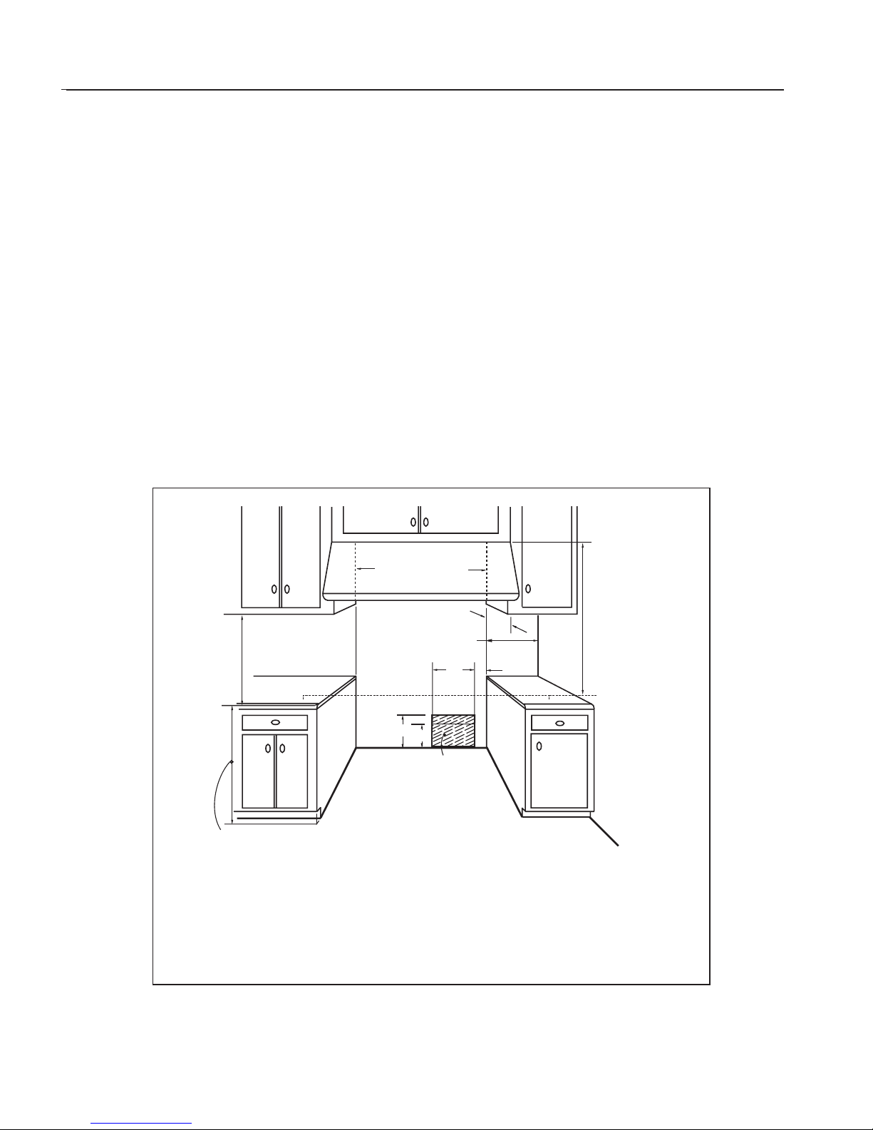
1) The range is a free standing unit. If the unit is to be
placed adjacent to cabinets, the clearances shown in
Fig.1 are required. The same clearances apply to island
installations .
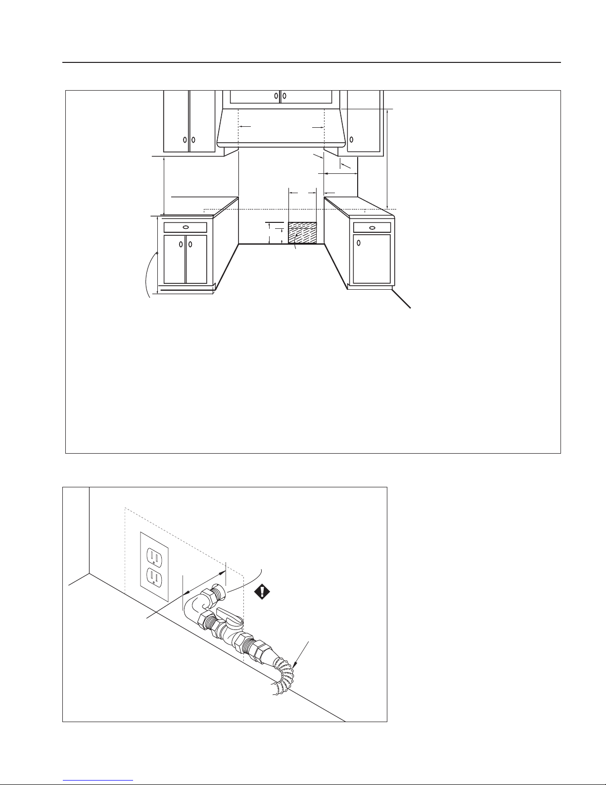
2) The range can be placed in various positions with
respect to the cabinet front,with the front either flush
or projecting, depending on the countertop depth
(See Fig.2, page 4).
3) The gas and electrical supply should be within the
zones shown in Fig.1 & Fig.3.
4) The maximum depth of ov er head cabinets installed on
either side of the hood is 13".
5) Any openings in the wall behind the range and in the
floor under the range must be sealed.
6) When there is less than a 12" clearance between
combustible material and the back edge of the range,
(above the cooking surface) a DCS Backguard must be
installed (see Fig.2). When clearance to combustible
material is over 12",a DCS island trim may be used (see
Fig. 2). The range comes equipped with island trim
standard.(Fig. 2) indicate the space required for each
type of backguard.
7) Always keep the appliance area clear and free from
combustible materials, gasoline and other flammable
vapors and liquids.
8) Do not obstruct the flow of combustion and ventilation
air to the unit.
min. 30" wide hood
CAUTION:
36" min. to
combustible
material ,
from cooking
surface
electrical + gas
supply
35-3/8" max. for level counter,
36-3/4" max. with range
leveling legs fully extended
12" min. to combustible
material , each side
cooking surface
C
D
B
As defined in the
“National Fuel Gas Code”
(ANSI Z223.1, latest edition).
The horizontal surfaces of the range top (cooktop) trim must not be below
countertop level.
A)
B)
C)
D)
E)
F)
7-1/2"
18" min.
3"
13" max.
4-1/2" (gas)
11" (electrical)
A
E
F
Fig. 1
Page 7
PRELIMINARY
7
INSTALLATION
2" Maximum
Protrusion from Wall
for Gas Supply
Gas Supply
Flex Line to Range
Manual Shut-Off
Valve must be
Easily Accessible
Fig. 3
Fig. 2
min. 30" wide hood
12" min. to combustible
material , each side
B
cooking surface
F
E
electrical + gas
supply
35-3/8" max. for level counter,
36-3/4" max. with range
leveling legs fully extended
As defined in the
“National Fuel Gas Code”
(ANSI Z223.1, latest edition).
The range height is adjustable. The level of the
range top must be at the same level or above the countertop level.
D
A
C
CAUTION:
36" min. to
combustible
material ,
from cooking
surface
A)
7-1/2"
B)
18" min.
C)
3"
D)
13" max.
E)
4-1/2" (gas)
F)
11" (electrical)
Page 8
PRELIMINARY
8
INSTALLATION ELECTRICAL / GAS CONNECTIONS
POWER REQUIREMENTS
120VAC,60 Hz.,single phase.
4 Amp.M ax.
(Use 15 Amp.Circuit)
Always disconnect electric supply cord from the wall
outlet or service disconnect before servicing this
appliance. Observe all governing codes and ordinances
when grounding, in the absence of which, observe
National Electrical Code ANSI/NFPA No.70-1990.
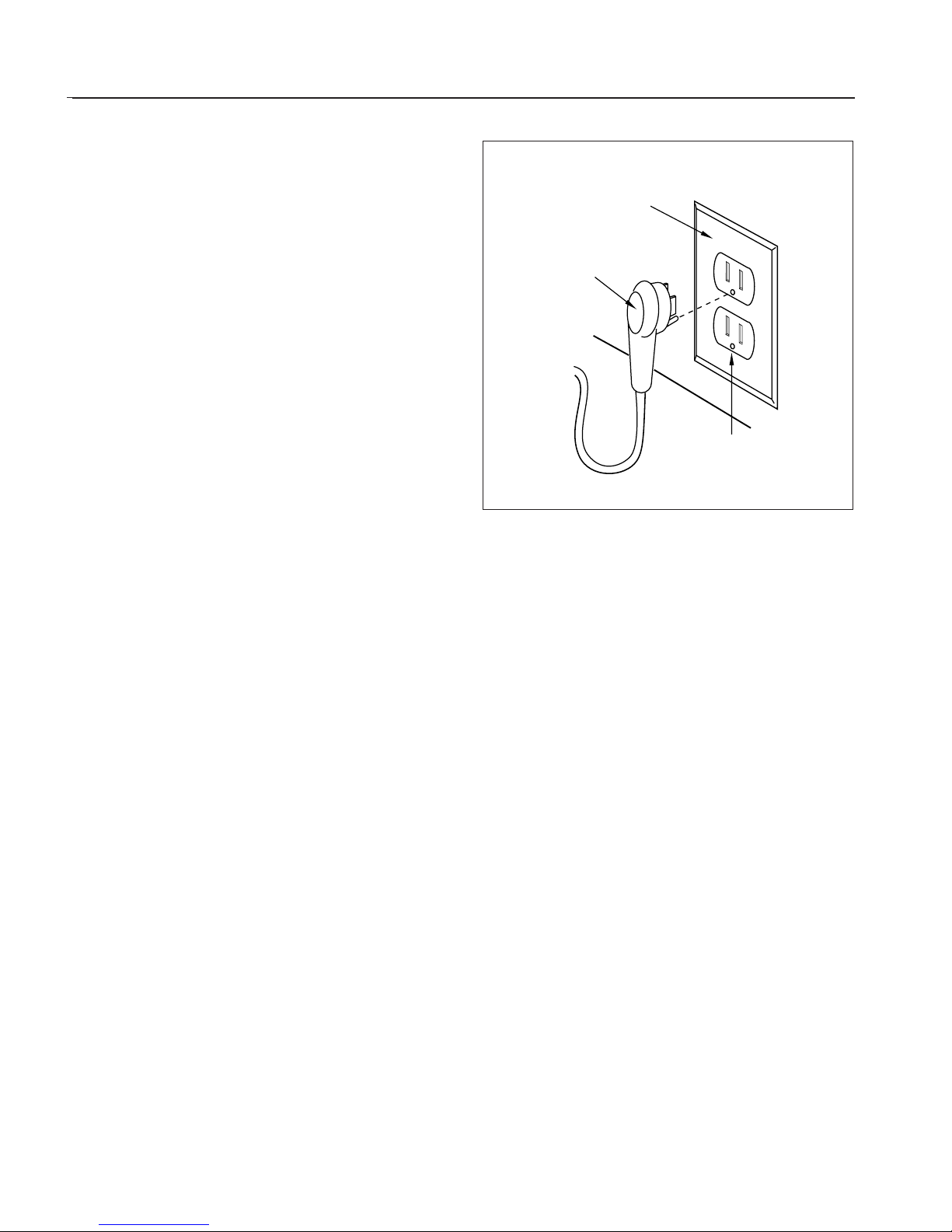
RECOMMENDED GROUNDING METHOD
This appliance is factory equipped with a power supply
cord with a three-prong grounding plug (with polarized
parallel blades). It must be plugged into a mating
grounding, type receptacle, connected to a correctly
polarized 120 Volt circuit. If the circuit does not have a
grounding type receptacle, it is the responsibility and
obligation of the installer or user to have the existing
receptacle changed to a properly grounded and
polarized receptacle in accordance with all applicable
local codes and ordinances by a qualified electrician. In
the absence of local codes and ordinances the receptacle
replacement shall be in accordance with the National
Electrical Code. THE THIRD GROUND PRONG SHOULD
NOT,UNDER ANY CIRCUMSTANCES,BE CUT OR REMOVED
(See Fig.4).
GAS
Verify the type of gas supplied to the location.The range
is shipped from the factory set up and adjusted for
natural gas.The unit can be readily converted to LP gas.
After LP conversion, burner adjustment may be
necessary.
NATURAL GAS REQUIREMENTS
Connection: 1/2" NPT Minimum 5/8" dia. flex
line.
Pressure: 6" to 14" W.C.
LP GAS REQUIREMENTS
Connection: 1/2" N.P.T. Minimum 5/8" dia.flex
line.
Pressure: Supply pressure must be 11" to 14"
W.C.
A regulator is required at the LP source to
provide a maximum of 14" W.C.to the range
regulator.
Receptacle Box
Cover Plate
Three Prong
Receptacle
Three
Prong
Plug
Fig. 4
Page 9
PRELIMINARY
9
INSTALLATION ELECTRICAL / GAS CONNECTIONS
HOOKUP
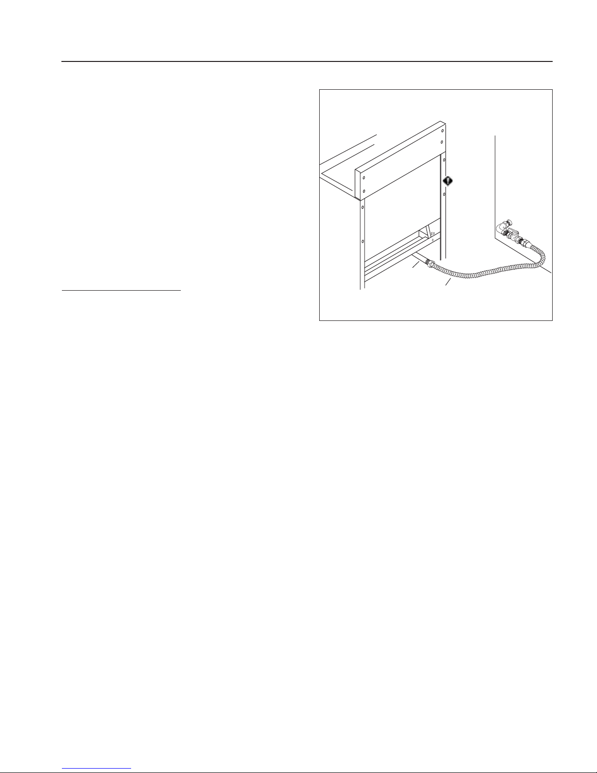
A manual valve is installed in an accessible location from
the front for the purpose of shutting off the gas supply.
The supply line must not protrude beyond the back of
the unit. Make sure the gas supply is turned off before
connecting the appliance. The flex line for the gas supply
must be metal and be approved by CSA,AGA,CGA OR UL.
Only use a metal supply hose, as the heat may cause a
rubber hose to melt and develop leaks. The gas supply
connections should be made by a qualified technician
and in accordance with local codes or ordinances.In the
absence of a local code,the installation must conform to
the National Fuel Gas Code ANSI 223.1-1988, latest
edition.
CAUTION:
The appliance must be isolated from the
building’s gas supply piping system by
closing its individual manual shut-off
valve du ri ng any pressure testing of the
gas supply piping system at test
pressures equal to or less than 1/2 psig
(3.5kPa.). The appliance and its
individual shut-off valve must be
disconnected from the gas supply
piping system during any pressure
testing of the system at the test
pressures in excess of 1/2 psig (3.5kPa.).
When checking the manifold gas
pressure, the inlet pressure to the
regulator should be at least 7.0”W.C.for
natural gas or 12.0”for LP.
When hooking up the gas supply from range rear hard
pipe to wall hard pipe, installation length of flex line
between range/wall hard piping must accommodate the
range being pulled from wall for cleaning or servicing
purpose. When range is pulled from wall,no strain should
occur at range or wall hard pipe connections (See Fig.5 ).
NOTE: Pipe sealer must be used on pipe thread
connections only.
Metal Flex Gas Line
Hard Pipe
1/2" NPT
Manual Shut-Off
Valve must be
Easily Accessible
WALL
Hard Pipe
Connection
Fig. 5
Page 10
PRELIMINARY
10
ANTI-TIP DEVICE INSTALLATION INSTRUCTIONS
ANTI-TIP DEVICE INSTALLATION
All ranges must have an anti-tip device correctly installed
as per these instructions. If you pull the range out from
the wall for any reason, make sure that the device is
properly engaged when you push the range back against
the wall. If it is not, there is a possible risk of the range
tipping over and causing injury if you or a child stand,sit
or lean on an open door.
INCLUDED PARTS:
Included with this kit are: (4) #10 x 2” wood screws, (1)
Anti-tip bracket,and (1) Installation Instructions.
INST ALLING THE KIT:
Instructions are provided for wood and cement floors.
Any other type or construction may require special installation techniques as deemed necessary to provide
adequate fastening of the Anti-tip bracket to the floor
and wall. The use of this bracket does not preclude
tipping of the range when not properly installed.
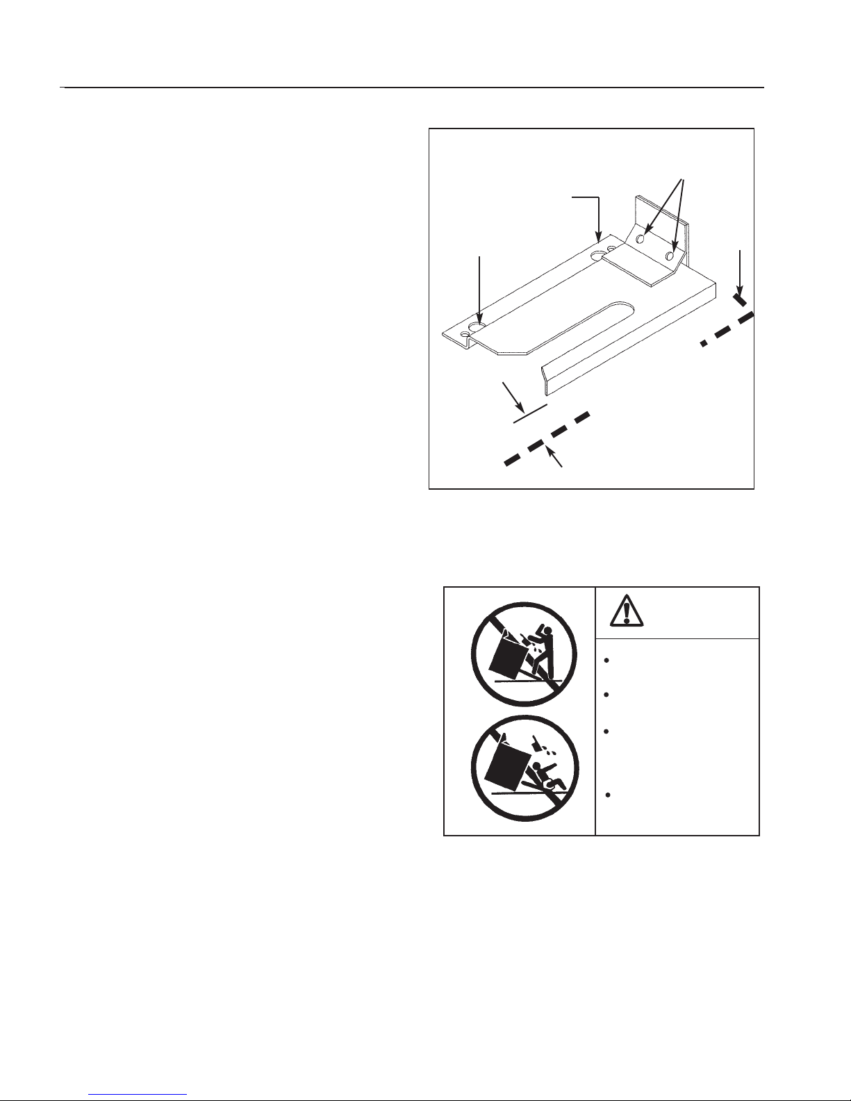
WOOD CONSTRUCTION:
Place the bracket against the back wall,into the right rear
corner where the range is to be located. Leave a gap
between the wall (or side of range) and the bracket of
3/4”.Drill (2) 1/8”diameter pilot holes in the center of the
small holes. A nail or awl may be used if a drill is not
available. Fasten the bracket securely to the floor and
wall. See Fig.6.
Concrete or cement construction:
HARDWARE REQUIRED:(2) sleeve anchors, lag bolts, and
washers (not provided).Locate the bracket as described
above. Drill the recommended size holes for the
hardware. Install the sleeve anchors into the holes and
then install the lag bolts through the bracket.The bolts
must be properly tightened as recommended for the
hardware. Fasten the bracket securely to the floor and
wall.
ONCE INSTALLED:
Complete the range installation per the instructions
provided with the product.Check for proper installation
of the Range and Anti-tip device by grasping the back of
the unit and carefully attempt to tilt the range forward.
Fig. 7
Fig. 6
(2) Large Holes for
Concret e I n stallations
(2)Small Holes for
Wood Installations
(2) Wood Screws into
Back Wall (All
Installations)
Back
Wall
RIGHT SIDE OF
WALL OR RANGE
3/4”
THE MANUFACTURE WILL NOT PAY
FOR ANY DAMAGE DO TO MISSING OR
IMPROPERL Y INSTALLED ANTI-TIP
DEVICE.
WARNING
ALL RANGES CAN TIP
INJURY COULD RESULT
INSTALL ANTI-TIP
BRACKET PACKED
INSIDE OVEN
SEE INSTRUCTIONS
Page 11

PRELIMINARY
11
BACKGUARD INSTALLATION
BACKGUARD INSTALLATION
The backguard is installed after the gas connection is
made.The backguard must be installed when there is less
than a 12" clearance between combustibles and the back
of the range (above the cooking surface) (See Fig. 1,
page 3).
BACKGUARD KITS:
The backguard is located,as shown in Fig.8. Secure the
backguard to the wall behind the range. Specific
instructions for installation of the full backguard or low
backguard can be found packaged with the backguard.
PROPER FLAME SIZES
The sealed top burners have an infinite number of heat
settings and there are no fixed positions on the control
knobs between HI and LO. To turn the sealed top burner
on, push in on the control knob and turn it counterclockwise to the “LITE”position.An audible clicking sound
will be heard. When the gas has been ignited by the
electronic spark igniter, turn the knob to the desired
setting.
OVEN BURNER
INFRARED BROIL BURNER
BLUE FLAME
COOKTOP BURNER
Fig. 8
Fig. 10
Fig. 11
Fig. 9
Wall Mount Full
Backguard
(Model No.BGS-3030)
Wall Mount Low
Backguard
(Model No.BGS-1230)
FLAME CHARACTERISTICS
Sealed Top Burner Lighting Note:
1-1/2" – 2"
1-1/2"
Page 12
PRELIMINARY
12
BURNERS
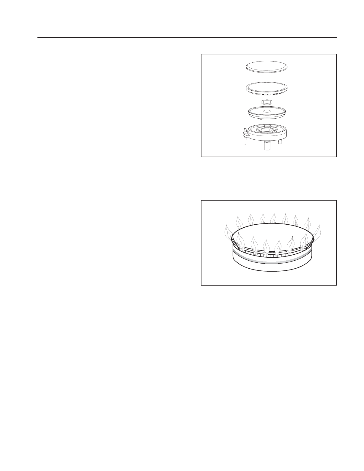
The professional gas range is equipped with burners
typical of those used in restaurants. These burners are
designed for maximum cleanability and controllability.
The large cap spreads the simmer burner heat out to
avoid too much heat being concentrated on the center of
the pan.The simmer burner is always on when the burner
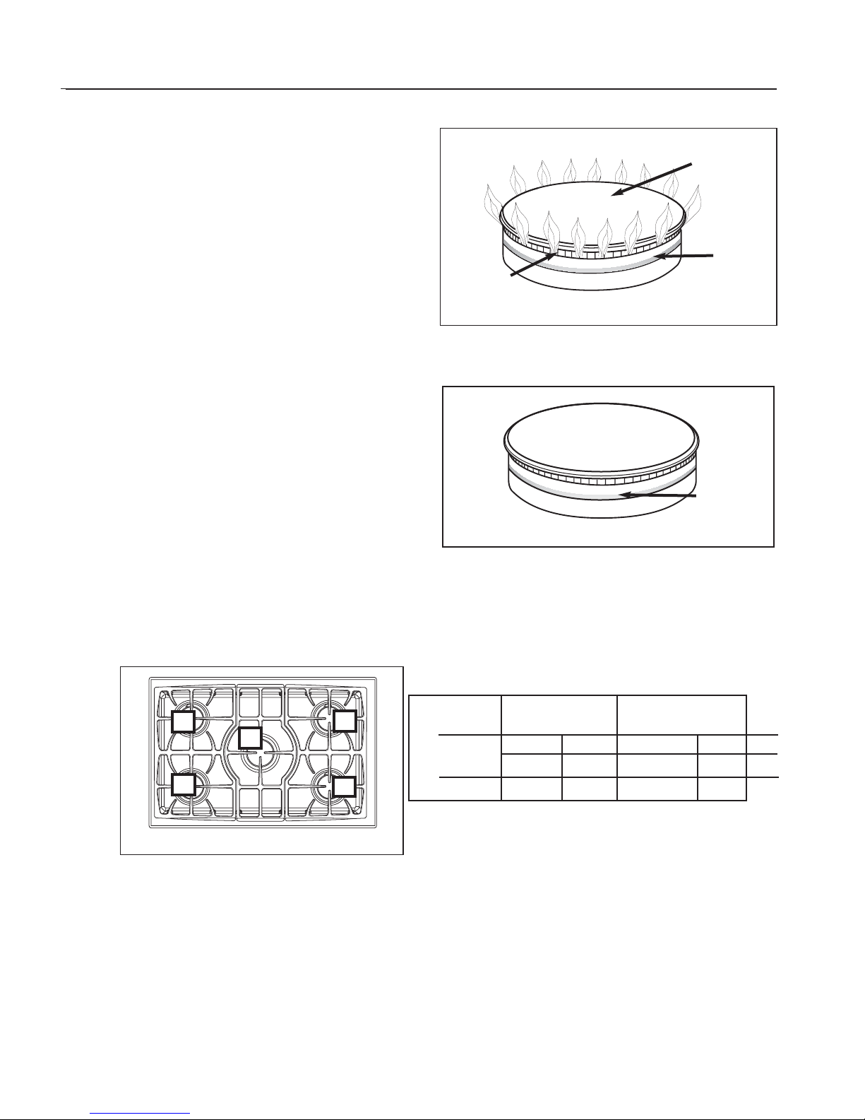
is in use.The burner should never be operated if the cap
is not in place.(Fig.12)
All the cooktop burners have electronic spark ignition to
eliminate continuously burning pilots, when the main
burner is on and the flame is blown out, it will relight
automatically.
Simmering
The professional cooktop has exceptionally low
simmering capabilities. The large cap serves as a heat
diffuser to spread out the heat to avoid having a center
hotspot. Keep in mind that because of the high heat
capacity of the outer burner,and the mass of the cast iron
burner grates (they retain heat longer than lighter,
conventional grates) some foods may continue to cook
by retained heat after the burner has been turned off.
After lighting the main burner,turn the main burner knob
down to the simmer burner position. Should a strong
draft or boil over extinguish the simmer flame it will
relight automatically as the main burner would.(Fig.13)
COOKTOP USE
Fig. 12
Fig. 14
Fig. 13
Simmer
Flame
Cap
Brass
Por t Rin g
Simmer
Flame
1
3
4
5
2
Burner Max. Low/Simmer
Location Btu/hr Btu/hr
Nat LP Nat LP
1,2,4,5 16,000 14,000 500-1,200 500-1,200
3 17,500 14,000 500-1,200 500-1,200
Page 13
PRELIMINARY
13
COOKTOP USE
ELECTRONIC IGNITERS
If a burner does not ignite,listen for the clicking sound.If
the igniter is not clicking,TURN OFF THE BURNER.Check
the circuit breaker for a blown fuse or a tripped circuit
breaker.(Fig.15)
BURNER EFFICIENCY AND FLAME
CHARACTERISTICS
It is necessary to keep the burner por ts and the igniters
clean for proper lighting and efficient performance of the
cooktop burners.
The burner flame should burn completely around the
burner with no excessive noise or lifting. The flame
should be blue in color and stable with no yellow tips.
(Fig.16)
An improper air-gas mixture may cause either a burner
flutter or a yellow tipped flame. A technician should
adjust the flame.During initial use,foreign particles in the
gas line,or dust in or in the air around the appliance may
cause an orange flame.This will disappear with use.
NOTE: If you are using propane gas,a slight pop or flash
may occur at the burner ports a few seconds after
the burner has been turned “off”. This “extinction
pop”is normal for propane gas.
Fig. 15
Fig. 16
Page 14
PRELIMINARY
14
OVEN USE
GENERAL
Your large new oven can be used in four cooking modes;
convection bake, regular bake, convection broil, or
regular broil.To help you decide which way to cook your
food read this information first.Remember this is a new
oven and the thermostat has been checked for accuracy.
Your old oven may have had a thermostat that over the
years got a little hot or a little cold.Check your recipes for
the correct time and temperature and don’t use the old
time or temperature you were using to compensate for
your old oven being off temperature.
Burners
Your new professional gas range is equipped with
bake and broil burners typical of those used in
restaurants. The oven broiler burner is 15,000
Btu/hr and the oven baking burner is
28,000 Btu/hr.
Electric Glow Igniter
The oven bake and broil burners are equipped
with an electric glow igniter and safety system
which lights the gas.There will be a delay after the
control knob has been turned on to when you
actually hear gas arrive at the burner. The burner
will ignite after the gas reaches the burner.
To Set the Oven for Convection Bake and
Bake
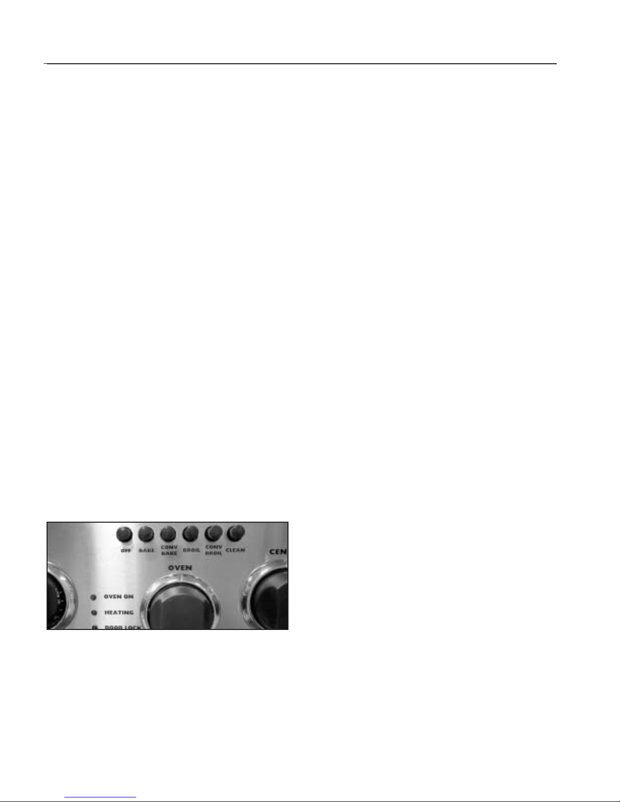
Decide if you are going to use CONVECTION BAKE or
BAKE. These cooking modes are for baking, roasting or
warming; using one, two, three or four racks. If you are
going to use regular Bake push the Bake Switch (located
on the Control Panel) and turn the oven control knob to
the temperature used in the recipe. To use Convection
USING CONVECTION BAKE AND REGULAR BAKE
Bake push the Convection Bake button (located on the
control Panel) and turn the oven control knob to the
temperature desired.
Preheating
Preheating takes about 10 to 15 minutes depending on
the temperature set. Preheating is usually necessary for
foods baked at high temperature for a short period of
time,i.e.drop cookies.The oven heating light will turn off
when the oven has reached temperature.
Condensation
During any cooking process there is a certain amount of
moisture that evaporates from the food.The amount of
moisture that condenses on the oven depends on the
moisture content of the food.The moisture will condense
on any surface that is cooler than the inside of the oven,
such as the control panel or the top of the door.
CONVECTION BAKE
Convection Bake is baking with a fan at the back of the
oven circulating the hot air in a continuous pattern
around the food. This circulating hot air heats and
browns the surface of the food more effectively than in a
standard oven.This allows most foods to be cooked at
lower oven temperatures or in less time,if baked at the
regular temperature. The air is recirculated and reheated.
Uncovered,longer cooking foods such as large pieces of
meat or other foods that can be cooked in low sided
baking utensils or air leavened foods,are where you will
see the most savings in cooking time. Using multiple
racks at the same time will achieve a good time saving,
as you can cook more food at the same time. The
number of recipes requiring preheating of the oven is
reduced considerably because the heat reaches the food
faster as the hot air circulates around the food.
Food s S uitable for Convection Bake
Air Leavened Foods (Angel Food Cake,soufflés,
cream puffs,meringue shells)
Appetizers
Breads
Main Dishes
Oven Meals (1 to 4 racks)
Cookies
Pies
Poultry
Roasts
Fig.17
Page 15

15
OVEN USE
Converting Recipes to Convection Bake
Low sided baking utensils will give the best results as the
hot air can reach all sides of the food easier. The oven
temperature can be left the same as the recipe and the
food cooked a shorter period of time. The temperature
can be lowered 25ºF to 50ºF and the food will probably
take the same length of time to cook as the recipe states.
If you find that food is adequately browned on the
outside, but not done in the center, lower the
temperature another 25ºF and add to the baking time.
When reducing the temperature always check the food
for doneness, a minute or two before the minimum
time stated in the recipe, as time can always be added.
Some recipes will cook faster than others.There is no way
to predic t exactly how long each recipe will take when
you convert it to convection.Convection will be easier to
use after you have used it a few times as you will begin to
understand the way it bakes.
Selecting Utensils for Convection Bake
Cooking by convection does not require any specially
designed baking utensils. You probably have many
utensils in your kitchen that are suitable to use. When
choosing a baking utensil,consider the material, the size
and the shape as they all affect the baking time, the
palatability and the appearance of the finished product.
Metal bakeware (aluminum,steel and cast iron) all result
in the fastest cooking time and the best end product.
Aluminum pans work best for all types of baked goods.
For the best browning ,use a pan with a dark or dull finish
that absorbs heat,when baking pies and breads. A shiny
finish works best for cakes and cookies, since it reflects
some of the heat and provides a more tender surface.
Cookie sheets with only one lip will give the best results,
as the heated air can circulate all around the sides of the
food. For roasting, use the bottom of the broil pan and
elevate the meat on a metal roasting rack.Glass-ceramic
or glass utensils do not conduct heat as well as metal,but
they can be used.Use them for foods that do not require
a dark brown crust or crisping,such as soufflés.
Baked items cook more quickly and evenly if they are
individually smaller in size,i.e.two or three small foods do
better than one large piece.When single food items are
baked,always center the food on the rack.If several foods
are being baked,space them evenly on the rack or racks.
Racks Positions
One to four racks can be used simultaneously during
convection baking.Place the rack(s) in the desired
position before turning the oven on.Store the unused
racks out of the oven.
Rack position 2 (second from bottom) will probably be
used the most for single rack convection baking.
When baking on more than one rack you do not need to
stagger the pans. Allow at least 1”of space between the
oven walls and the pans so the heated air can circulate.
Pans should be placed in center of oven,stacked above
each rack.
Regular Bake
Bake is baking with hot air;there is no fan.The air
movement comes from natural convection - as the air
heats,it moves to the top of the oven. This oven mode is
the same as you have been using for baking on one or
two racks.
Food s S uitable for Bake
Appetizers
Pies,Cakes
Breads
Desserts
Main Dishes
Oven Meals (1 to 2 racks)
Poultry
Roasts
CAUTION:
Aluminum foil should never be used to
cover the oven racks or to line the oven
bottom. The trapped heat can damage
the porcelain and the heated air cannot
adequately reach the food being baked.
Rack Positions
One or two racks can be used simultaneously during
bake. Place the rack(s) in the desired position before
turning the oven on. Store any unused racks out of the
oven.
Rack position 2 (second from bottom) will probably be
used the most for single rack baking.
If you are using two racks simultaneously, be sure to
check the food on the bottom rack sooner than the
minimum time.The food on the lower rack position may
PRELIMINARY
Page 16
OVEN USE
16
cook slightly faster than the food on the upper rack,
particularly if you are using large baking utensils. If you
are using two racks simultaneously, be sure to stagger
the baking utensils so that one is not directly above the
other and the heated air can circulate freely around each
pan. Allow at least 1” of space between the oven walls
and the pans.
If using large or commercial size baking utensils,the food
may take a few extra minutes as the air cannot circulate
as freely as it does with a smaller pan. When using
commercial size baking utensils,use only one rack as the
heat does not have the room to circulate.
To Get the Best Results
Baking:
Follow the recipe amounts and ingredients,
including the size and shape of the baking
utensil recommended in the recipe.
Do not open the oven door “just to peek”,use
the interior oven light and look
through the window.
Do not use the oven for storage, especially
when baking in the oven. Extra utensils, not
being used for baking, can affect the food
product, baking time, browning, and end
result.
If you are using glass utensils,lower the
temperature 25ºF.
Use a minute timer and set it for the minimum
time suggested in the recipe.
Convection B ak i ng:
Follow the first three recommendations
above.
Metal utensils give better results,in
convection,than do glass baking utensils.I f
you use glass,it usually is not necessary to
lower the temperature an additional 25ºF.
Use a minute timer and set it for less than the
minimum time suggested in the recipe. The
first time you use a recipe in the convection
mode,be sure to note the new baking time on
your recipe for future reference.
Be sure to read the basic information on
convection before using the oven for the
first time,page 14-16.
Keep in mind that convection baking results
vary,depending on type of product. In many
cases standard bake yields superior results
over convection.
USING CONVECTION BROIL AND BROIL
To Set the Oven for Convection Broil and
Broil
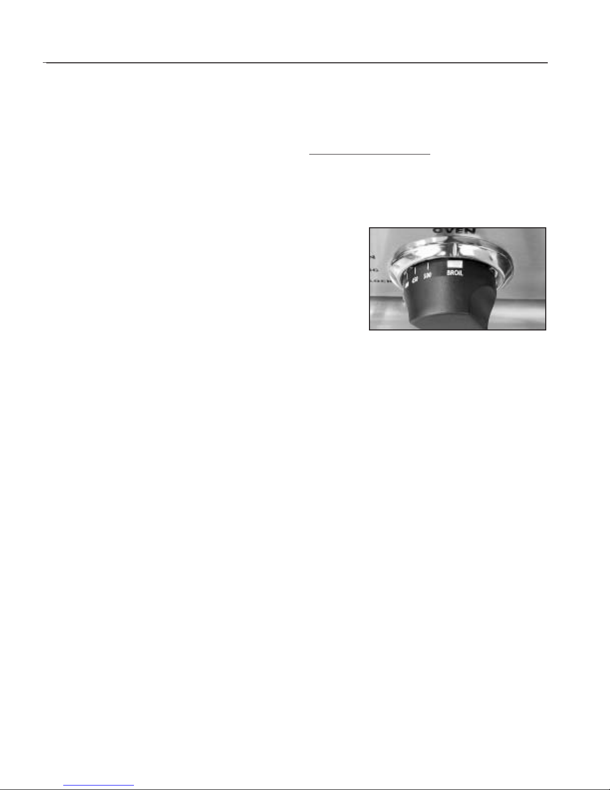
CAUTION:
Pay special attention when setting the
Oven Control knob on “BROIL”.If you set
the knob past the “BROIL” setting, the
burner will not ignite.
Decide if you are going to use BROIL or CONVECTION
BROIL.If you are going to use regular broil push the Broil
button (located on the Control Panel) and turn the Oven
Control knob to “BROIL”.To use Convection Broil push the
Convection Broil button (located on the Control Panel)
and turn the Oven Control knob to “BROIL”.The burner
will ignite after the gas reaches the burner.The “oven on”
indicator light will come on to let you know that the
broiler is currently on. During the broiling process, the
infra-red burner produces such an intense heat that the
burner will cycle on and off to maintain an efficient yet
safe interior cooking environment.
The HEATING indicator light on the valve panel cycles on
and off with burner to let the user know when the burner
is lit.This cycling process is used to evenly distribute and
safely control the intense heat that the broil burner
produces.The cycling feature prevents the burner from
producing range-damaging heat.
Rack Position
The rack position depends on the type and thickness of
the food. Thick pieces of meat or poultry (1” or more)
would typically be broiled or convection broiled on rack
position 3.Steaks,chops and hamburger would typically
be broiled on rack position 4.If top browning casseroles
or bread, the thickness of the food would indicate the
rack position. Casseroles and bread would typically be
PRELIMINARY
Fig. 18
Page 17

17
OVEN USE
browned on rack position 2 (see instructions below for
more information).( The numbering of the rack positions
is from the bottom to the top - #1 being the bottom
position)
Preheating
For b est b roiler performance, preheating for 10 minutes
improves searing of the food’s outside layer, seals in
natural juices and flavors, gives a more even cooking
pattern,and takes less time to cook.
Convection Broil
Convection Broil is cooking by intense infrared radiant
heat supplied by the broil burner while a fan at the back
of the oven circulates hot air in a continuous pattern
around the food. Convection broil cooks the food with
better results for thicker cuts of meat.The meat sears on
the outside and retains more juices and natural flavor
inside with less shrinkage.
Food s S uitable for Convection Broiling: rack position
(#1 is from
bottom to
top)
Thicker Cuts of Meat (1”or more) #3
Thicker,Irregular-sized Pieces of Poultry
(1”or more) #2 or #3
Thicker Pieces of Fish (1”or more) #3
Top Browning:Casseroles and Breads #2 or #3
Regular Broil
Broil is cooking by intense infrared radiant heat supplied
by the broil burner located at the top of the oven.
Food s S uitable for Broiling: rack position
Appetizers #3 or #4
Meats,Poultry,Fish (under 1”) #4
Top Browning:Casseroles and Breads #2 or #3
NOTE: The broiler pan for both broiling and convec-
tion broiling should be placed all the way to
the back of the oven and centered on the rack
for best results.
Using a M eat Thermo meter to Broil and
Convection Broil
To accurately determine the doneness of a thick steak or
chop (1-1/2 inches thick or more), use a meat
thermometer. Insert the point of the thermometer into
the side of the meat to the center. Cook the first side to
90ºF for rare meat. Cook the first side to 100ºF for
medium to well done. Cook the second side to the
desired degree for the doneness you want, 140ºF to
145ºF for rare,and 150ºF to 155ºF for medium and 160ºF
to 165ºF for well done. If you are cooking pork, cook to
160ºF.
A large two-piece broil pan comes with your new range.
When you are broiling, always use both pieces. Do not
cover the grid with aluminum foil.This slotted grid allows
the grease drippings to flow into the bottom of the pan
keeping it away from the intense heat of the infra-red
broiler burner. This helps to minimize the smoking and
spattering of the grease.
To Get the Best Results
Defrost the food before starting to cook.
Put food on broiler pan, center and push broiler
pan to the very back of oven rack.
Set a minute timer for the minimum time to check
the food.
Steaks should be at least one inch thick, if a rare
doneness is desired.I t is difficult to get rare with
meat that is thinner,or to get a nice brown piece
of meat.
After half the total cooking time, turn the food
over only once.It is not necessary to turn over thin
foods (fillet of fish, ham slices, etc.). Liver slices
must be turned over.
Use a two-piece broil pan. Two-piece broil pans
are designed to minimize smoke and spatter. DO
NOT cover the slotted grid with aluminum foil.
This will catch the grease and could cause a fire.
When top browning use metal or glass-ceramic
bakeware.DO NOT use heat-proof glass or pottery
as this type of glassware cannot withstand the
intense heat of the broiler burner.
NOTE: You c annot use the broiler burner and the bak e
burner at the same time. When one is on,the
other cannot be turned on.
PRELIMINARY
Page 18

PRELIMINARY
18
OVEN USE
NOTES:
High Altitude Baking
Recipes and baking times vary if you are baking at a
high altitude. For accurate information write to the
Agriculture Extension Service, Colorado State
University, Fort Collins, Colorado 80521. Specify the
type of information and the baking mode
(convection bake or bake) you need, i.e. cakes,
cookies, breads, etc. There may be a cost for the
bulletins.
To Us e t he O ven for Slow Cooking or Low
Temperatures
The oven can be used to keep hot food hot, to
dehydrate food, to warm plates,for slow cooking (as
in a crock pot),and to defrost foods.
You can keep hot, cooked food at serving
temperature. Set the oven to the temperature
suggested in the chart. Rare meat must be eaten
when it is removed from the oven, as it continues
cooking from its own heat.
To keep food moist, it must be covered with
aluminum foil or a lid.
To dehydrate food,follow suggestions in a recipe.
To warm plates, check with the dishware
manufacturer for the temperature for the
recommended.
To use the oven as a slow cooker set the oven control
knob to 225ºF. Place the food in the oven in a pan
with a tight fitting lid.Follow recipes for this type of
cooking.
To thaw uncooked frozen food,set the oven control
knob to “warm”.Be sure the food is tightly wrapped in
foil. Thaw the food just enough to handle it. Cook
immediately.Do not refreeze.
To thaw frozen cooked food, set the oven control
knob to 170ºF. Loosen the freezer wrapping.Do not
use plastic wrap or wax paper in the oven.
FOOD SAFETY:
According to the United States
Department of Agriculture you
should not hold foods at temperatures between 40ºF to 140ºF for
longer than 2 hours.
Page 19
PRELIMINARY
19
BURNERS
For proper lighting and performance keep the burners
clean. It is necessary to clean the burners if they do not
light even though the igniter clicks, if there has been a
severe boil over, or when the flame does not burn blue.
Be certain all burner knobs are in the off position before
attempting to clean the burners.The burners have been
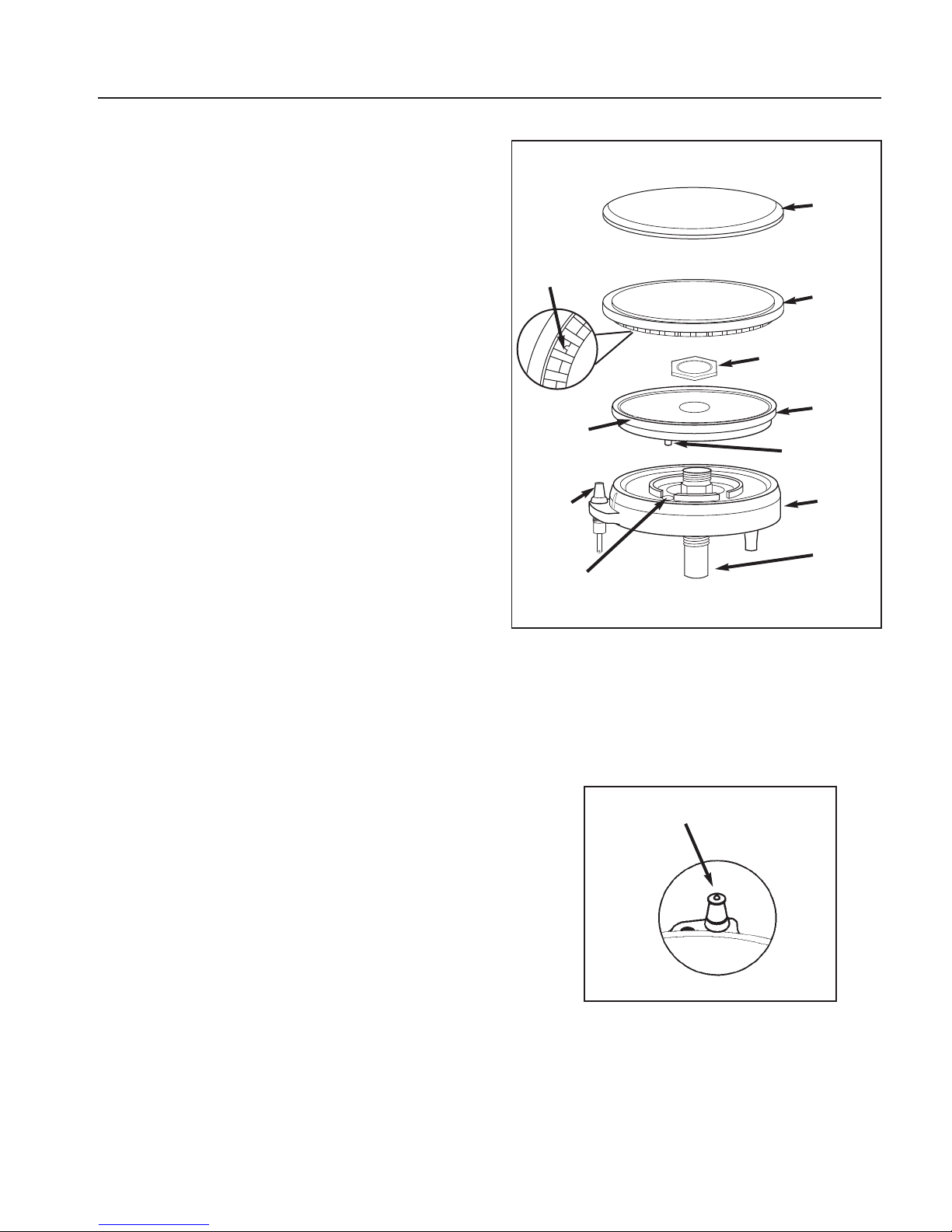
designed for ease in cleaning. When the grates and
burners are cool, remove the grate. The Burner Cap and
the Brass Port Ring can easily be lifted off. Wash these
parts in hot soapy water, rinse and dry thoroughly. The
Burner Caps are porcelain enamel, follow the directions
on the previous page that were given for the burner
grates. A bristle brush can be used to clean out the
toothed burner ports, if necessary. Disassembly of the
Simmer Ring is not recommended, however, it may
become necessary to do so if the ports remain clogged
after normal cleaning.If it is necessary to disassemble the
Simmer Ring from the Base, remove the Hex Nut at the
top of the Simmer Ring.Clean the Simmer Ring with hot
soapy water using a soft wire or plastic bristle brush then
dry thoroughly.Re-assemble the parts using the Hex Nut.
After cleaning,it is impor tant to make sure the Locating
Pin on the bottom side of the Simmer Ring is properly
aligned with the corresponding hole in the Base and that
the Locating Pin (see insert) in the bottom side of the
Brass Port Ring is properly aligned with the Locating
Notch on the top side of the Simmer Ring. Incorrect
alignment will produce a potentially dangerous flame
and poor burner performance.See Fig.19.
IGNITERS
Wipe with a water dampened cotton swab.Be careful not
to damage the igniter.(S ee Fig.20)
CONTROL KNOBS - COOKTOP AND OVEN
These are plastic and can be cleaned in hot,soapy water.
To remove the knobs from the control panel, grasp the
knob and pull straight towards you.Wash, do not soak.
Rinse and dry thoroughly.I t is important to replace these
knobs on the correct gas valve on the control panel.
CARE AND MAINTENANCE
IGNITER (keep clean)
Cap
Main
Burner
Port
Ring
Burner
Base
Simmer
Ring
Electrode
Venturi
Locating
Notch
Locating Pin
Hole Inside
Brass Ring
Locating Pin
Locating Pin
Hex Nut
Fig. 19
Fig. 20
Page 20
PRELIMINARY
20
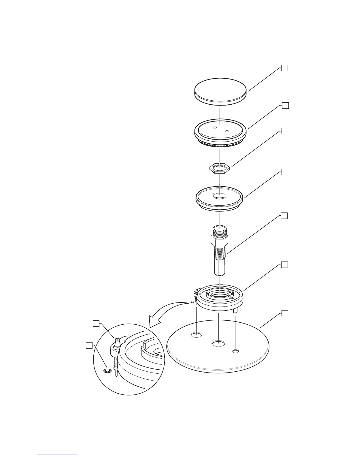
SEALED BURNER DISASSEMBLY
TO R E P LAC E TH E BURNER IGNITERS, FOLLOW
THESE STEPS:
A) Remove burner cap (#1).
B) Remove main burner port ring (#2).
C) Using a 11/16”socket remove the brass nut (#3),which
secures the simmer ring (#4).
D) Remove the simmer ring.
E) Using a 13/16”sock et,remove the venturi (#5) from the
center of the burner base.
F) Lift up burner base (#6) exposing the igniter wire.
Remove the wire and set aside the burner base.
G) The igniters (#8) located on the burner base flange can
be removed by removing the “c”clip (#6),which secures
them to the burner bases (#6).
H) After removing the clip and spring (#9) pull igniter (#8)
straight up from burner base assembly (#6).
1
2
5
6
3
4
7
8
9
Page 21
PRELIMINARY
21
COMPONENT ACCESS
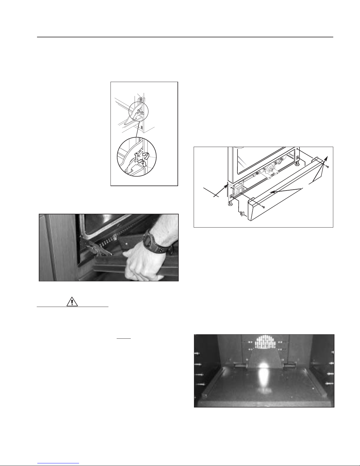
OVEN DOOR REMOVAL
1.Open the door in the full open position.
NOTE: Light pressure
may have to be
applied on the
door to close
the hinge latches.
2. Rotate locking tabs on
hinges so that bottom and
top are locked together
(fig.21).
3. The door can then be
removed by lifting and
pulling the door on
approximately 60º angle
with the hinges up and out
of the front frame (fig.22).
WARNING:
The door is about 33 pounds.
NOTE: If in event that the oven door comes off track, or
becomes misaligned, the door MUST be removed from
the range in order to reset the hinges. Open the door to
the broil stop. Get a firm grip on the door.Remember the
door is heavy. Lift the door and pull at the same time to
remove the range. It is normal to hear a loud bang when
the door is being removed. Once the door has been
removed,lay it down on a protected floor with the handle
down.With protection on your hand,lean over the top of
the door and push the large hinge away from the door to
connect the small hinge to the large hinge using the lock.
Note that the longer arm is spring loaded and is VERY
hard to move.Once the hinges are set, the door can be
reinstalled.Place the door at the same angle when it was
removed. Evenly slide the door back into place and check
to assure the hinges rest in the center of each door hinge
roller. With the oven door fully open,unlock the hinge
latches and the door is ready to close again.
If this procedure does not correct the misalignment,
contact DCS Customer Care Center (See page 51).
KICK PANEL REMOVAL
1.Disconnect power supply
2.Remove the two (2) Phillips head screws securing kick
plate (fig.23).
3. Pull the bottom of the kick panel out to unsnap clips
and remove.
BAKE IGNITER
1.Disconnect power supply
2.Follow step in door and kick panel removal (fig.21,22,
23).
3. Remove oven racks and oven floor by slipping floor
forward and up to remove (fig.24).
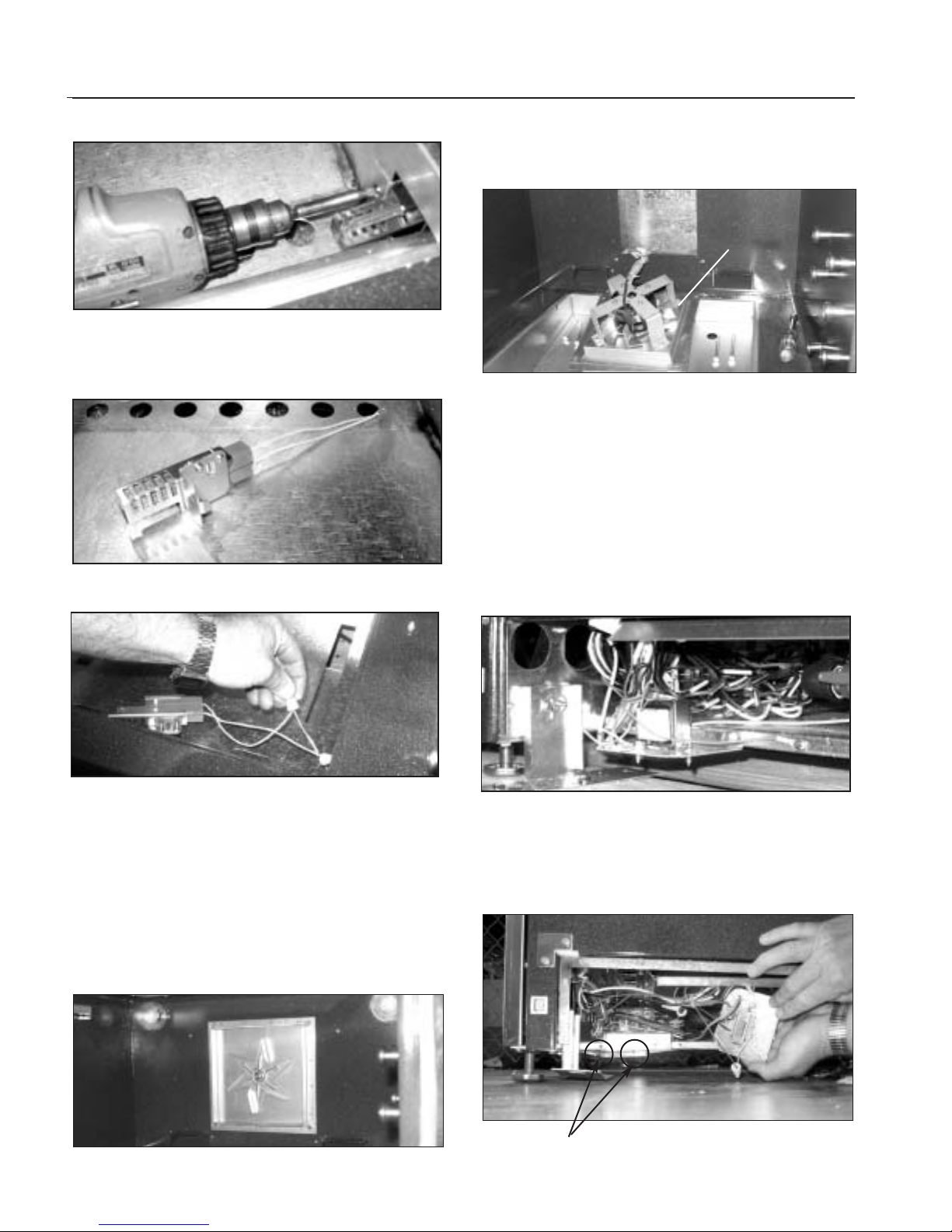
4. Locate igniter, remove screw.
Gently pull igniter out of location (fig.25).
Fig. 21
Lock
(close)
Unlock
Fig. 22
Fig. 23
Clip
Screws
OVEN
BOTTOM
Fig. 24
DOOR HINGE ROLLER
Page 22
PRELIMINARY
22
COMPONENT ACCESS
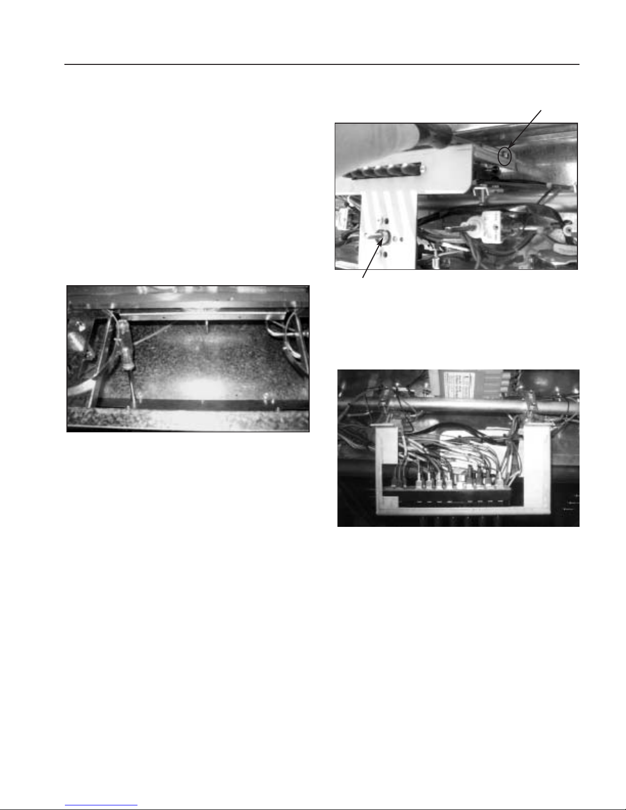
5. Follow wire through oven wall to connection below.
Remove wire nut (fig.26 and 27).
CONVECTION FAN
1. Follow door removal (fig. 21 and 22). Remove oven
racks and oven floor.
2. Remove the two (2) screws holding the convection
baffle in place.
3.Remove the (4) bolts holding convection cover in place.
Remove cover (fig.28).
4. Remove four 7/16” bolts holding convection motor
assembly (fig 29).
5.Support motor assembly inside oven and remove wire
nuts.
TRANSFORMER AND RELAY ASSEMBLY
1.Disconnect power supply
2.Follow kick panel removal step (fig.23).
3. Removed (2) 5/16” bolts holding transformer bracket.
Disconnect wire harness (fig.30).
4.Remove (2) 5/16”bolts holding the relay bracket. Slide
the bracket forward out of the location tab on the
backside,taking care not to damage wires (fig.31).
Fig. 25
Fig. 26
Fig. 27
Fig. 30
Fig. 31
Mounting
screws
Fig. 29
Fig. 28
Motor
Page 23

PRELIMINARY
23
COMPONENT ACCESS
REGULATOR MANIFOLD ASSEMBLY
1. Pull oven away from wall,making sure gas and electrical supply is turned off at the valve,and gas line is disconnected.
2. Loosen and remove 15/16” brass flare nut from
aluminum gas feed line at bottom,center of unit
(fig.32).
3. Remove the three (3) 5/16”bolts holding pipe brackets to back of unit (fig.32).
4. Remove the two (2) phillips head screws securing kick
plate. Remove kickplate (fig.23).
5. Remove the two (2) 5/16”bolts holding brackets on
either side of the regulator (fig.33).
6. Remove 5/8” brass flare nut at right hand side of “ T”,
right side of regulator (fig.34).
7.Pulling towards you,remove regulator manifold
assembly.
MOTORIZED LATCH
1.Follow kick panel removal step (fig.23) and disconnect
power supply.
2.Remove the four (4) phillips head screws,holding latch
bracket (fig.35).
3.Remove wires from switches and motor. Remove latch
assembly.
4. Remove the four (4) screws of the access cover (fig.36).
5. Remove bracket.
Fig. 33
Bracket
Mounting
screws
Fig. 32
Fig. 34
Fig. 35
Fig. 36
Page 24
PRELIMINARY
COMPONENT ACCESS
24
BROILER ASSEMBLY/IGNITER REMOVAL
WARNING:
Disconnect circuit breaker and turn off
the main gas valve prior to performing
the following procedure...
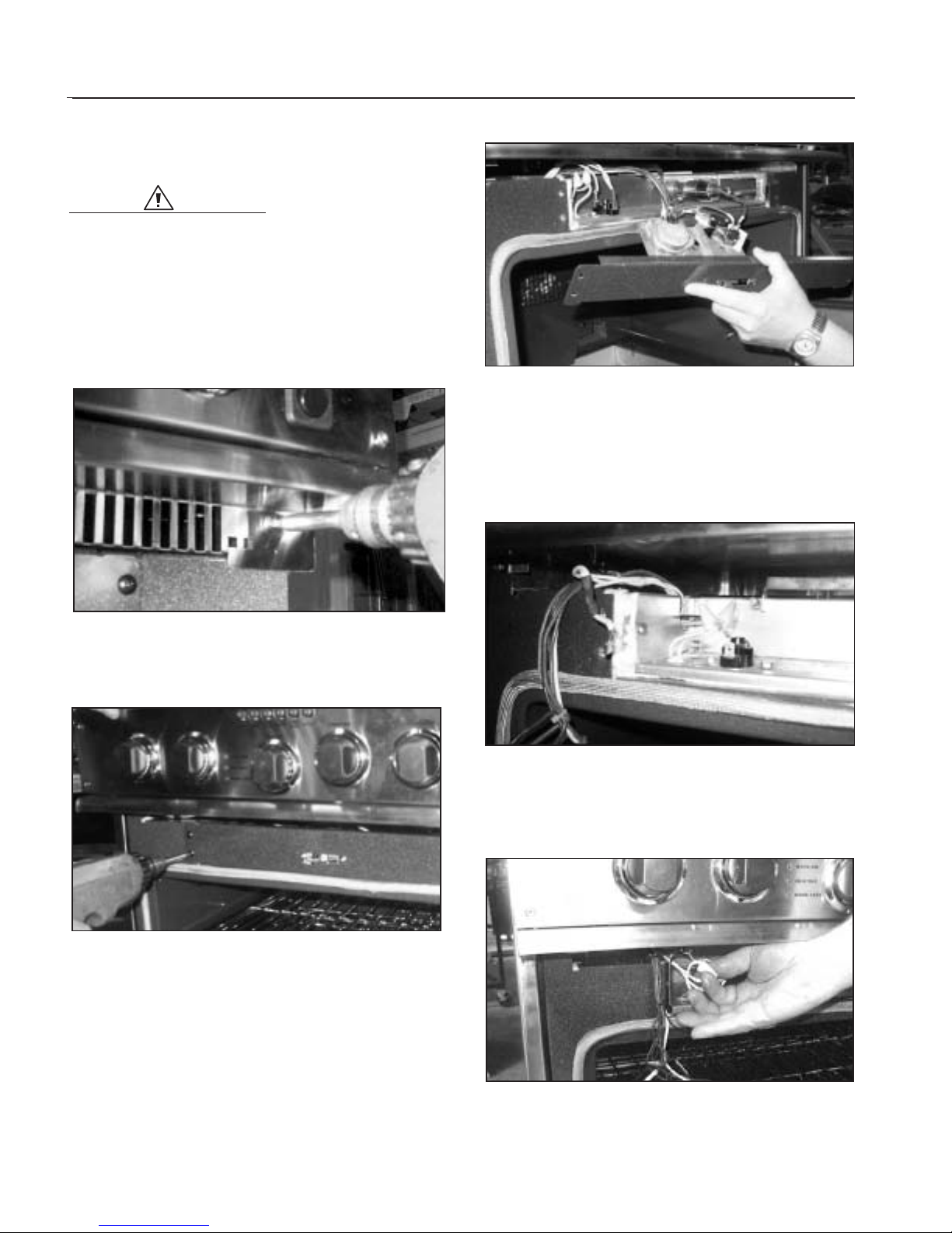
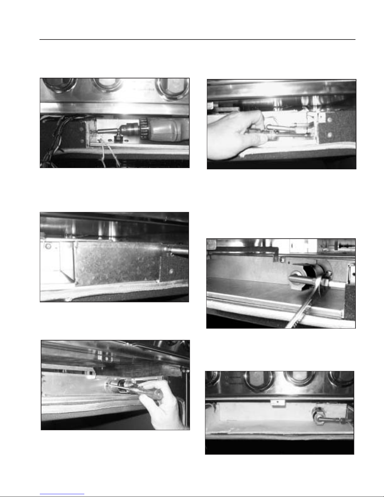
1.Remove the three (3) phillips screws securing the wire
cover panel located in the top of the oven door
opening (fig.37).
2.Remove the four (4) black phillips screws securing the
access cover (fig.38).
3.Remove the access cover,taking care not to disconnect
or damage any wires or plugs connected to it (fig.39).
4.Carefully gather wires and direct them up through the
slot located in the rear left corner of the cavity. This will
allow access to the mounting screw located on the left
front side panel. Also disconnect the two (2) wires fr om
the high limit switch (fig.40).
5. Remove the two (2) ceramic wire nuts located on the
left side of the opening,and disconnect the 2 wires (fig.
41).
Fig. 37
Fig. 38
Fig. 39
Fig. 40
Fig. 41
Page 25
25
COMPONENT ACCESS
PRELIMINARY
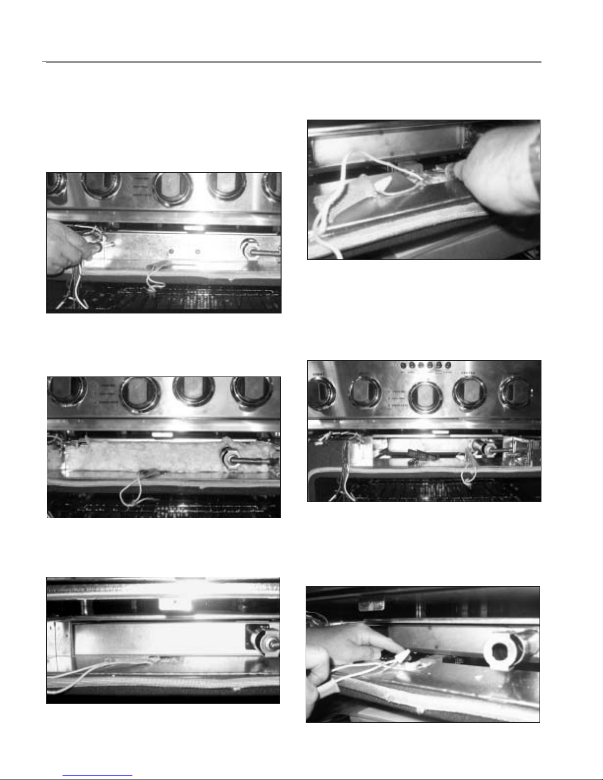
6. Remove inner panel phillips screw (1) located on the
left, front, side panel (fig.42).
7. Remove the phillips screws (2) securing the venturi
cover located on the right side of the opening.
Remove the cover (fig.43).
8.Remove the two (2) phillips screws and venturi shutters
at the base of the burner tube (fig.44).
9. Remove the 5/16”hex head screw (1) located on the
right side panel of the opening (fig.45).
10. Remove panel by tilting up and back while sliding
panel out past broiler tube assembly.
11.Disconnect the gas line fitting.Temporarily secure the
fitting nut to keep it from sliding down the tube into
the range side wall cavity (fig.46).
12. Remove insulation taking care to note the exact
location of the insulator for correct re-assembly
(fig.47).
Fig. 42
Fig. 45
Fig. 46
Fig. 43
Fig. 44
Fig. 47
Page 26
COMPONENT ACCESS
26
PRELIMINARY
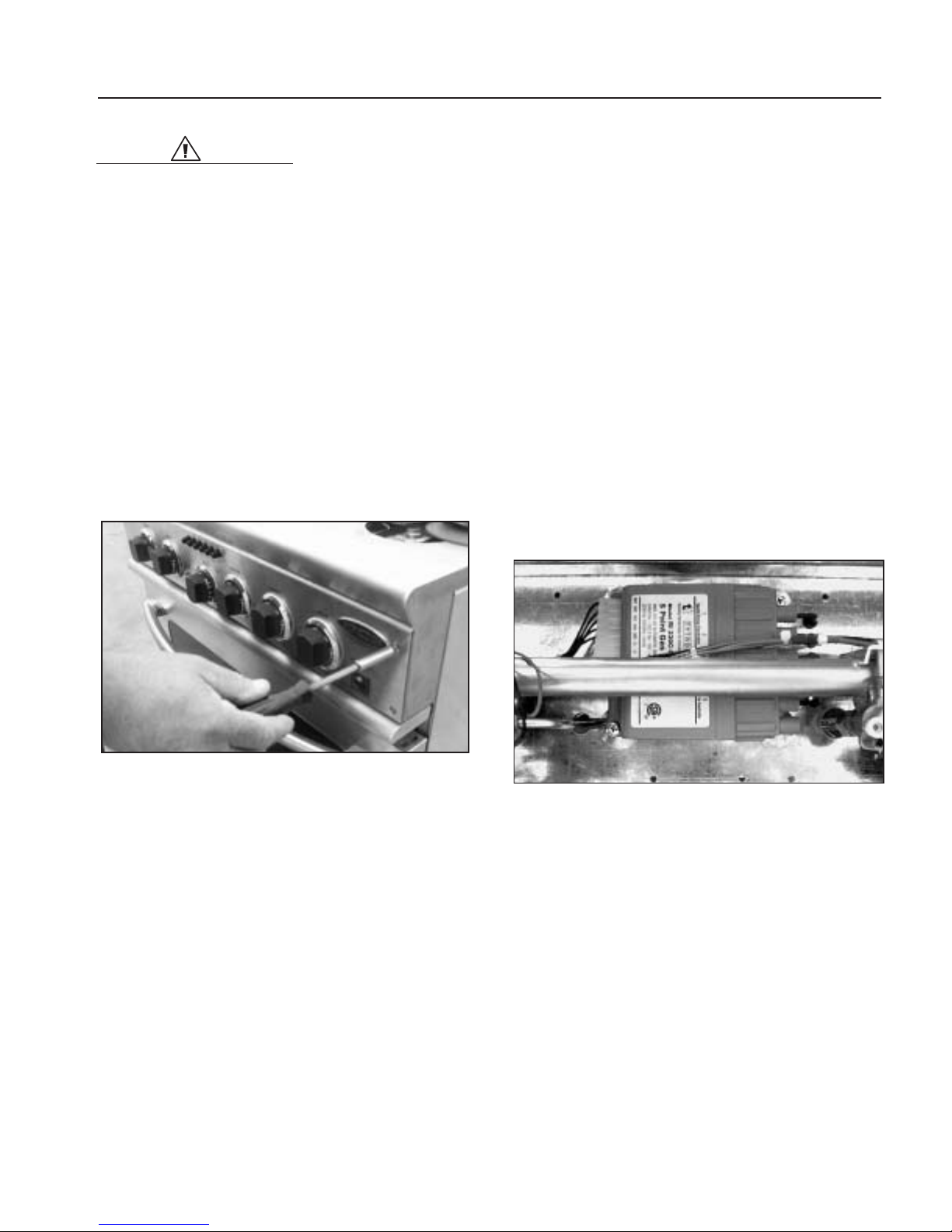
13. Remove the two phillips screws (2) securing the
center bracket to the panel.Remove the bracket by
lifting up and out.Remove the two (2) phillips screws
located on the left and right side of the panel.
Remove the panel by pulling out the left side and
sliding the right side past the broiler tube (fig.48).
14.Remove insulation from panel. Again take note of it’s
exact location for correct re-assembly (fig.49).
15.Remove the panel by pulling it straight out (There are
no screws or fasteners on this panel) (fig.50).
16. Remove the two (2) 5/16 “ hex head screws securing
the igniter assembly (fig.51).
17. Rotate the igniter assembly approximately 120
degrees counter clockwise and remove the igniter
assembly. Remove the two wire nuts from the
igniter, disconnect the wires and remove the igniter
(fig.52).
18. Grasp the broiler assembly by it’s tube and pull it
straight out of the unit. To install the new broiler
assembly or igniter reverse the dis-assembly
procedure (fig.53).
Fig. 48
Fig. 49
Fig. 50
Fig. 51
Fig. 52
Fig. 53
Page 27
PRELIMINARY
27
COMPONENT ACCESS
WARNING:
For safety reasons, it is essential that
these insulating materials are
reinstalled after servicing the unit in
exactly the same locations from which
they were removed. Failure to follow
this warning will result in failure of the
the unit to operate properly and could
result in loss of property and/or serious
injury to the user.
CONTROL PANEL REMOVAL
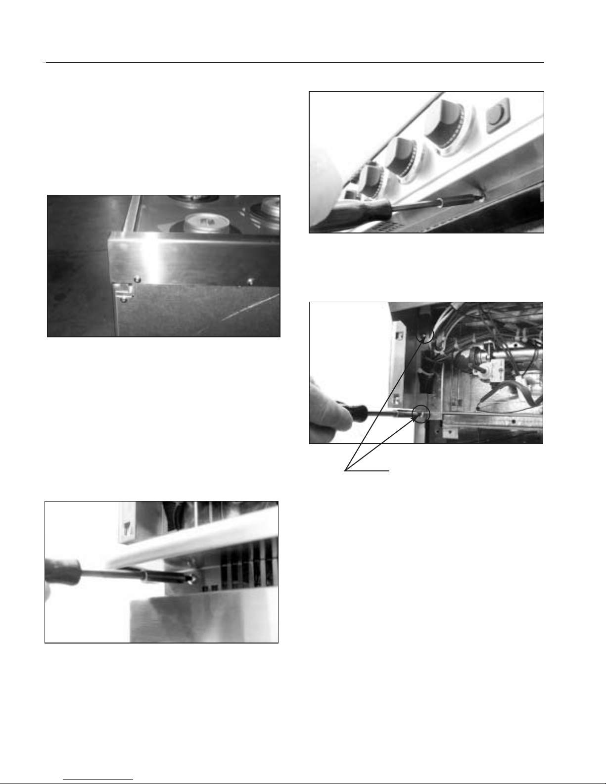
1. Follow kick panel removal (fig. 23) and disconnect
power supply.
2.Remove the four (4) #15 torx head screws from control
panel (fig.54).
3.Open door to the broil stop possession and cover with
clean cloth (to protect door and control panel).
4.Remove knobs.Lay panel forward on door.
5.Disconnect wire to light switch and indicator.
SELECTION SWITCH
1. Follow kick panel removal (fig. 23) and disconnect
power supply.
2.Remove the four (4) #15 torx head screws from control
panel (fig.54).
3.Open door to the broil stop possession and cover with
clean cloth (to protect door and control panel).
4.Remove knobs.Lay panel forward on door.
5.Disconnect wire to light switch and indicator.
6.Remove selector switch mounting screws (fig.61).
7.Remove selector switch and bracket.
8.Remove wires.Note wire location on switch.
BURNER RE-IGNITER
1. Follow kick panel removal (fig. 23) and disconnect
power supply.
2.Remove the four (4) #15 torx head screws from control
panel (fig.54).
3.Open door to the broil stop possession and cover with
clean cloth (to protect door and control panel).
4.Remove knobs.Lay panel forward on door.
5.Remove the selector switch and bracket.
6.Remove the two (2) phillips screws securing the reigniter to the inner panel (fig.55).
7. Disconnect the Molex plug from the left side of the reigniter.
8. Remove the five (5) igniter “plugs”from the right side
of the re-igniter.
9.Taking care not to disturb other wires and connectors,
remove the unit from behind the manifold tube.
TOP B U RNERS
1.Remove burner grates
2.See sealed burner disassembly on page 17.
Fig. 55
Fig. 54
Page 28
PRELIMINARY
28
COMPONENT ACCESS
TOP ASSEMBLY
1. Pull oven away from wall,mak ing sure gas supply is
turned off at the valve,and gas line and electrical are
disconnected.
2. Remove the four (4) phillips head screws from island
trim where it attaches to the back panel (fig.56).
3. Remove the all knobs and then the four (4) #15 torx
head screws from control panel front (fig.54).
4. Remove upper burner assemblies and remove top
from unit. (See page 17 burner disassembly).
5. Remove wire guard and trim assembly from front of
unit. (fig’s 57 & 58).
6. Remove the four (4) phillips head screws from bull
nose trim assembly,two on either side (fig.59).
7.Pull thermo bulbs from oven cavity
8. Lift top up to a 45 degree angle and pull straight
towards you.
COOLING FAN MOTOR
1. Pull oven away from wall,mak ing sure gas supply is
turned off at the valve,and gas line and electrical are
disconnected.
2. Remove the four (4) phillips head screws from island
trim where it attaches to the back panel (fig.56).
3. Remove the four knobs and then the four (4) #15 torx
head screws from control panel front (fig.54).
4. Remove upper burner assemblies and remove top
from unit. (See page 17 burner disassembly).
Fig. 56
Fig. 58
Fig. 57
Fig. 59
4 phillips head
screws
Page 29
29
COMPONENT ACCESS
5. Remove wire guard and trim assembly from front of
unit. (fig’s 57 & 58).
6. Remove the four (4) phillips head screws from bull
nose trim assembly,two on either side (fig.59).
7. Pull thermo bulbs from oven cavity
8. Lift top up to a 45 degree angle and pull straight
towards you.
9. Remove the nine (9) 5/16”bolts,holding motor bracket,located on the inside of the burner box assembly
(fig.60).
10. Remove wires and remove assembly.
11. Remove the three (3) phillips head screws and two
nuts and bolts. Remove motor from bracket.
OVEN THERMOST AT
1. Follow kick panel removal (fig. 23) and disconnect
power supply.
2.Remove the four (4) #15 torx head screws from control
panel (fig.54).
3.Open door to the broil stop possession and cover with
clean cloth (to protect door and control panel).
4.Remove knobs.Lay panel forward on door.
5.Disconnect wire to light switch and indicator.
6.Remove selector switch mounting screws (fig.61).
7.Remove selector switch and bracket.
8.Remove wires.Note wire location on switch (fig.62).
9.Remove thermostat-mounting screws (fig.61).
10. Remove wire guard and trim assembly from front of
unit (fig.57 and 58).
11.Remove capillary bulb from holder inside oven cavity.
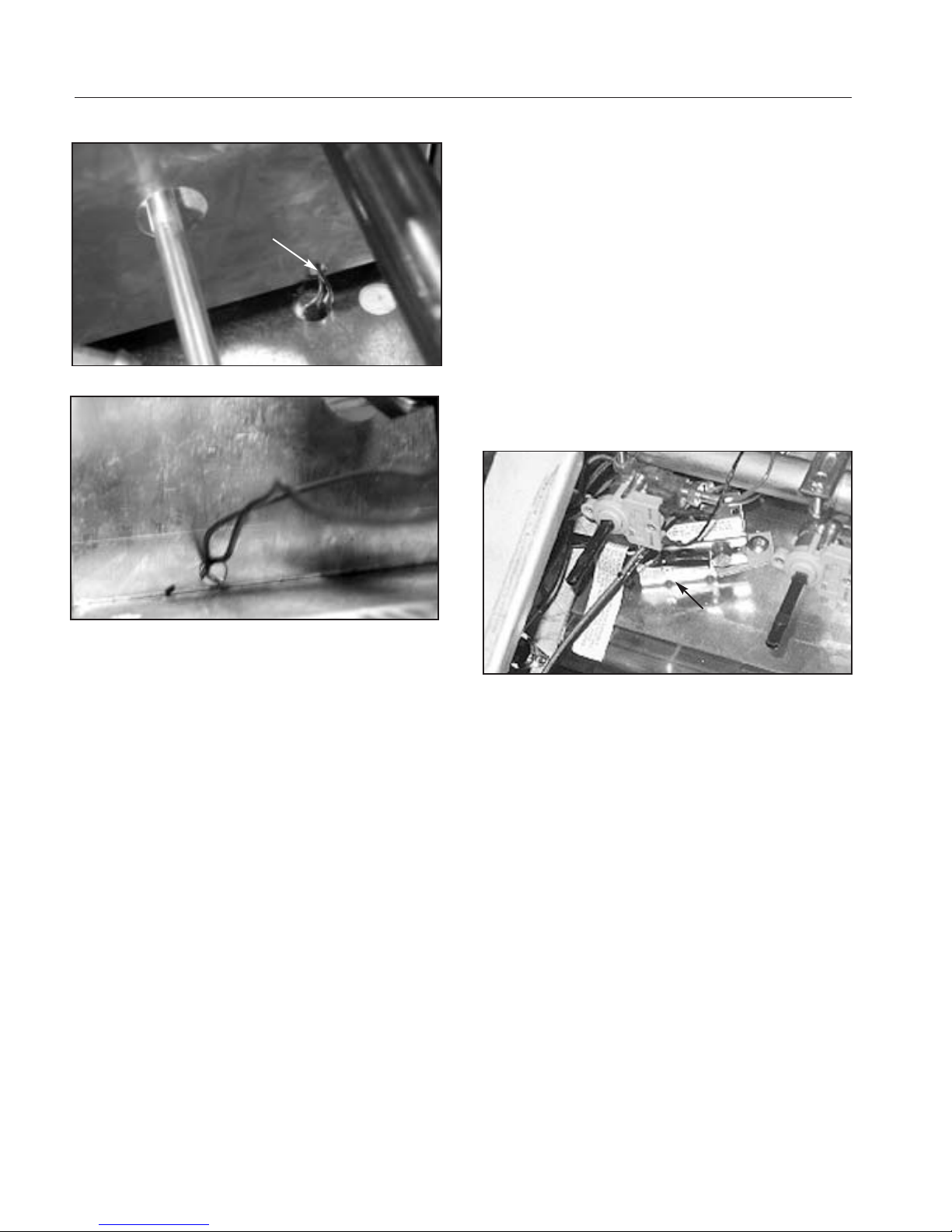
12. Feed capillary bulb up through hole in oven cavity
and back through panel (fig.63 and 64).
PRELIMINARY
Fig. 60
Fig. 61
Mounting Screw
Thermostat
Fig. 62
Page 30
PRELIMINARY
COMPONENT ACCESS
LOCK THERMOSTAT
1. Follow kick panel removal (fig. 23) and disconnect
power supply.
2.Remove the four (4) #15 torx head screws from control
panel (fig.54).
3.Open door to the broil stop possession and cover with
clean cloth (to protect door and control panel).
4.Remove knobs.Lay panel forward on door.
5.Disconnect wire to light switch and indicator.
6.Remove selector switch mounting screws (fig.61).
7.Remove selector switch and bracket.
8.Remove thermostat-mounting screws (fig.61).
9. Remove wire guard and trim assembly from front of
unit (fig.57 and 58).
10.Remove capillary bulb from holder inside oven cavity.
11. Feed capillary bulb up through hole in oven cavity
and back through panel (fig.63 and 64).
12.Unscrew thermostat from bottom of control panel.
CLEAN THERMOSTA T
1.Disconnect power supply.
2.Remove the four (4) #15 torx head screws from control
panel (fig.54).
3.Remove selector switch mounting screws (fig.61).
4. Remove clean thermostat mounting screw (fig.65).
5.Remove wires from clean thermostat.
6.Car efully remove thermostat assembly from inner
panel.
Fig. 65
thermostat
Fig. 63
Fig. 64
Capillary
Assembly
Page 31

PRELIMINARY
31
TROUBLESHOOTING
CONDITION CHECK
No Bake
No Broil
No Clean
Not Locking and Un-Locking
Burners Not Lighting
Cook i n g Complaints
Bake igniter 3.0 amp to 3.3 amp draw ATC continuity
Oven T-Stat contacts
Main gas valve “OFF”
Selec tor switch contacts 30 – 33: 40 – 43
Dual safety valve continuity
Broil igniter 3.0 amp to 3.3 amp draw HTC continuity
Oven T –Stat contacts
Main gas valve “OFF”
Selector switch contacts (3-31;30-34;56-36;57-37;40-42)
Dual safety valve continuity
See “Clean Relay Sec tion”
See motorized latch
See above
See motorized latch
See “Clean Relay Sec tion”
Check supply voltage 120 VAC
Check for spark at burner
Igniter dirty
Check igniter switches
Check igniter module
Check operating gas pressure
See “Cooking Section”
Page 32

PRELIMINARY
32
COMPONEN T CLOSED CONTACTS
1) “Latch close switch” C - NC
2) “Selector switch” 35 - 55
3) “K4 Relay” 8 - 2
4) “K3 Relay”coil energized N/A
5) “K3 Relay” 4 – 7
6) Lock Motor energized N/A
CLEAN RELAY LOCKING
Page 33
PRELIMINARY
33
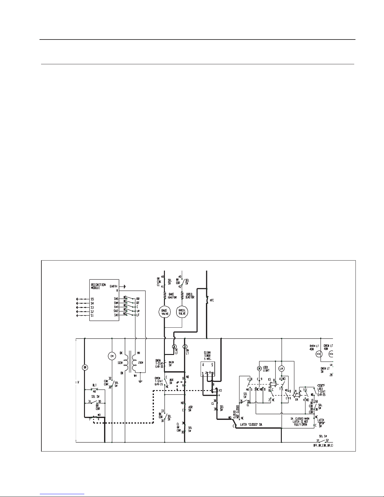
CLEAN RELAY HEATING (LOCKED)
COMPONENT CLOSED CONTACTS
1) “Latch close switch” C - NO
2) “Selector switch” 39 - 38
3) “Clean timer ” 1 - 2
4) “K1 Relay”coil energized N/A
4a) “Blower motor”energized ( K1 ) 4 - 7
4b) “A ir switch”closes,
5) “Selector switch” 34 - 30
6) “K1 Relay” 9 - 6
7) “Oven T-Stat”Micro switch contacts N/A
8) “Bake valve”energized N/A
9) “Bake igniter ”energized N/A
10) “ Selector switch” 40 - 41
11) “High-Temp cut-out” N/A
Page 34
PRELIMINARY
34
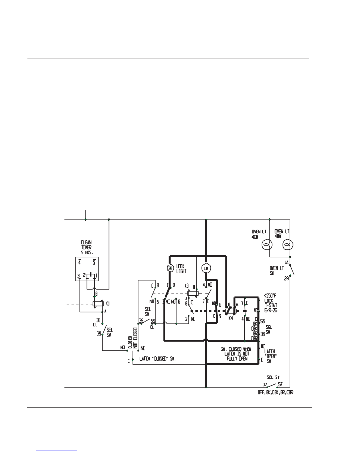
CLEAN RELAY UNLOCKING
COMPONENT CLOSED CONTACTS
1) “Selector switch”“Off”pos. N/A
2) “Oven temperature less than 550°F N/A
3) “Latch open switch” C – NC
4) “Selector switch” 36 - 56
5) “Lock T-Stat” C – NO
6) “K4 Relay”coil,energized N/A
6a) “K4 Relay” 9 - 6
6b) “Latch motor”,energized N/A
Page 35
PRELIMINARY
35
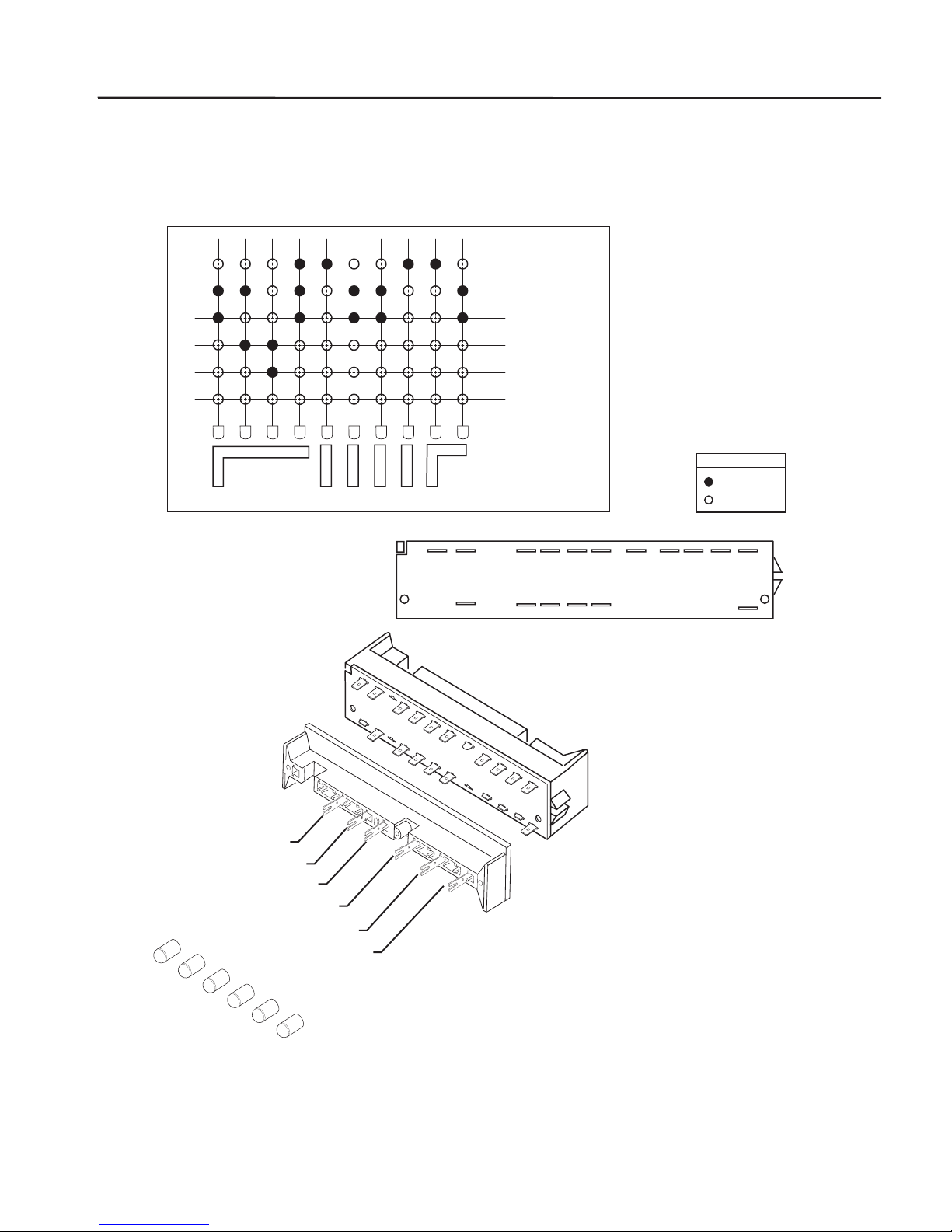
PUSH BUTTON SWITCH
CLEAN
CONV BROIL
BROIL
CONV BAKE
BAKE
OFF
31 32 33 34 35 36 37 39 41 42
CLEAN
CONV. BROIL
BROIL
CONV. BAKE
BAKE
OFF
LEGEND
OPEN
403857565530
CLOSED
42 41
40
39 37 36 35
38 57 56 55
34 33 32 31
30
Page 36
PRELIMINARY
36
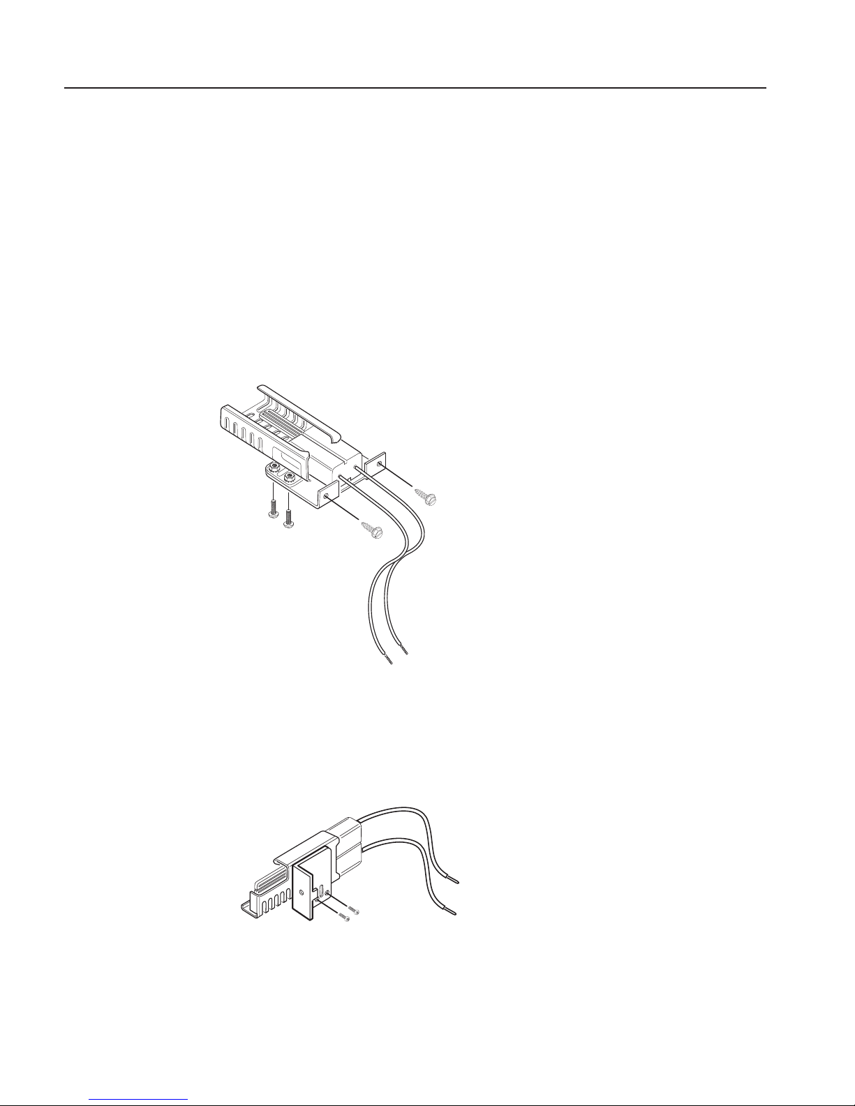
OVEN AND BROILER IGNITER
Both the bake and broil burners use a hot surface ignition
system.The safety valve operates by current,not voltage.
The igniter resistance decreases,allowing more current to
flow to the safety valve, as the surface temperature
increases.
From a cold start it can take as long as 60 seconds, with
voltage applied, to reduce the resistance sufficiently to
provide a minimum of 2.9 amps of current flow in the
series circuit.The igniter should provide a current flow of
between 3.2 and 3.7 amps. At this point the igniter
temperature is between 1800 and 2500 degrees F. The
igniter will remain energized as long as the thermostat is
"calling for heat". If the igniter glows red and does not
draw at least 3.0 amps,the fault is probably in the igniter,
not the safety valve.
BROIL IGNITER
(p/n 16009-1)
OVEN IGNITER
(p/n 16505)
Page 37
PRELIMINARY
37
SERVICE BULLETIN
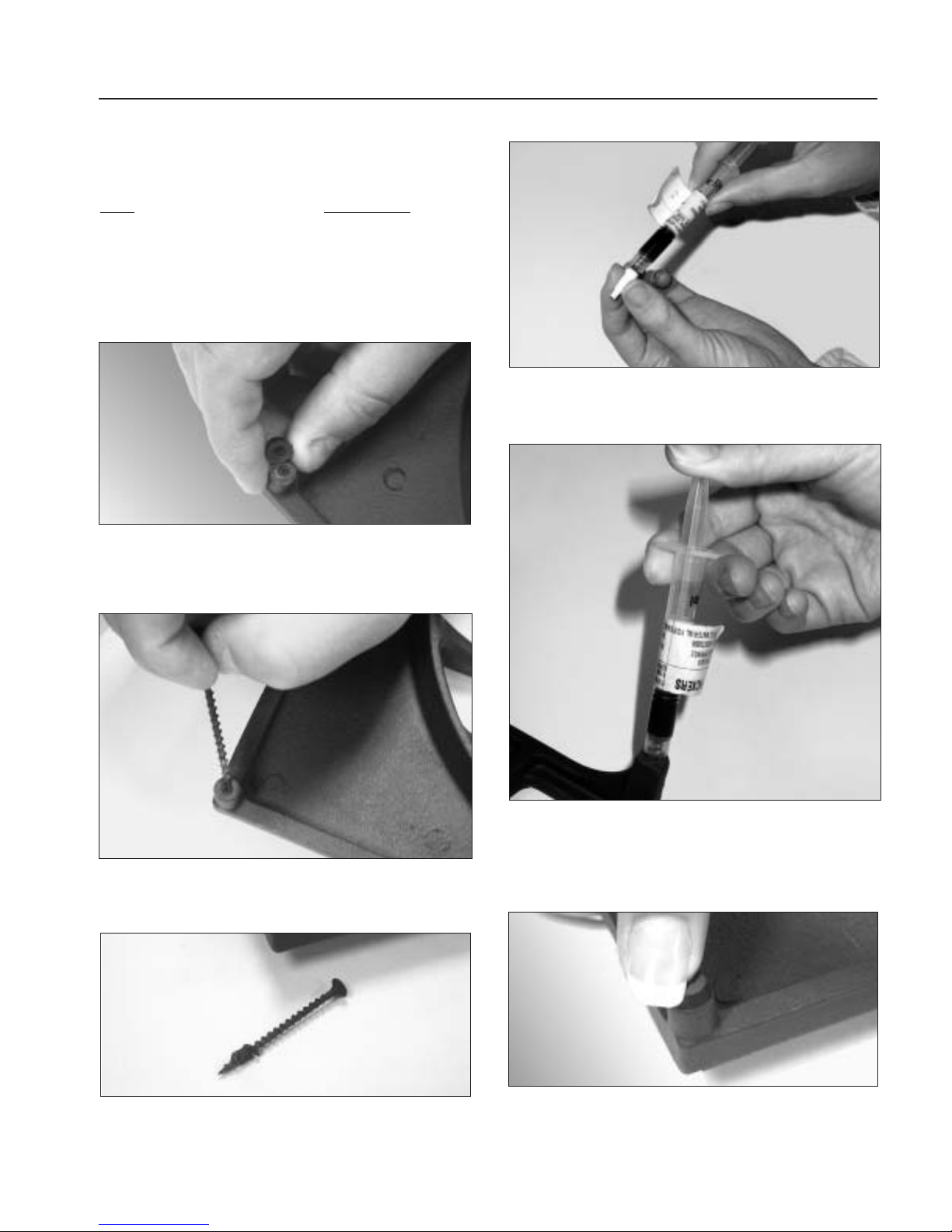
FOOT KIT REPAIR – K-14355
Parts Part Number
Rubber feet (12) 14355
Syringe/adhesive (1) 25301
Drywall screw 6 x 2-1/4 (1) 15103
1.Remove the bumper cap.
Note:the rubber foot may be broken or missing.
2.Use a dry wall screw to extract the remaining bumper
material from the grate hole (s).
3.Rotate the screw clockwise to extract the old bumper
stem.
4.Take the cap off the syringe by unscrewing it.
5.Apply a small amount of the adhesive in the grate
hole. Press the new bumper (s) into each of the grate
holes while slightly twisting.
6.Verify that the bumper (s) are fully seated in their
respective holes.
Page 38
PRELIMINARY
38
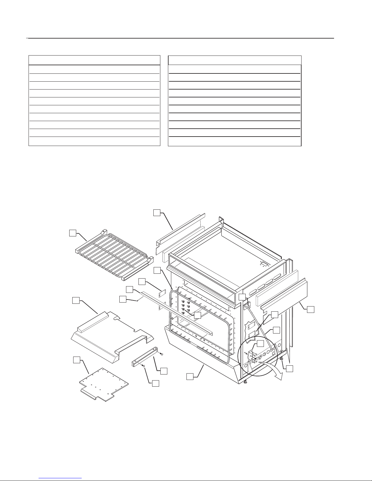
RANGE BODY ASSEMBLY
ITEM PART NO. DESCRIPTION
1 91658 RACK,OVEN (3 PLCS)
2 14052 30”OVEN GASKET
3 91657-02 WLDMT RLR SUPT LH (2 PLCS)
4 91944 WIRE GUARD COVER
5 15001-09 SCREW (3 PLCS)
6 91494-PC OVEN BOTTOM
7 14197-02 ROLLER,RACK
8 91499 PLATE,FLAME SPREADER
9 15001-23 SCREW,MACHINE (2 PLCS)
10 91709 BRACKET,BULBS
ITEM PART NO. DESCRIPTION
11 91682 KICK PLATE,SILVER
91682-01-PA KICK PLATE,WHITE
91682-02-PA KICK PLATE,BLACK
12 18052-2 LEVEL LEG (AFTER TEST)
13 91712 BRACKET SUPPORT,VENTURI
14 91722 PIPE BROILER
15 91657-01 WLDMT RLR SUPT R/H (2 PLCS)
16 91704-01 SIDE SHIELD R/H
91704-02 SIDE SHIELD L/H
17 16071 GROMMET,WHITE
1
2
3
4
5
6
7
8
9
10
11
12
13
14
15
16
17
16
SEE PAGE 43
2
8
SEE PAGE 43
Page 39
PRELIMINARY
39
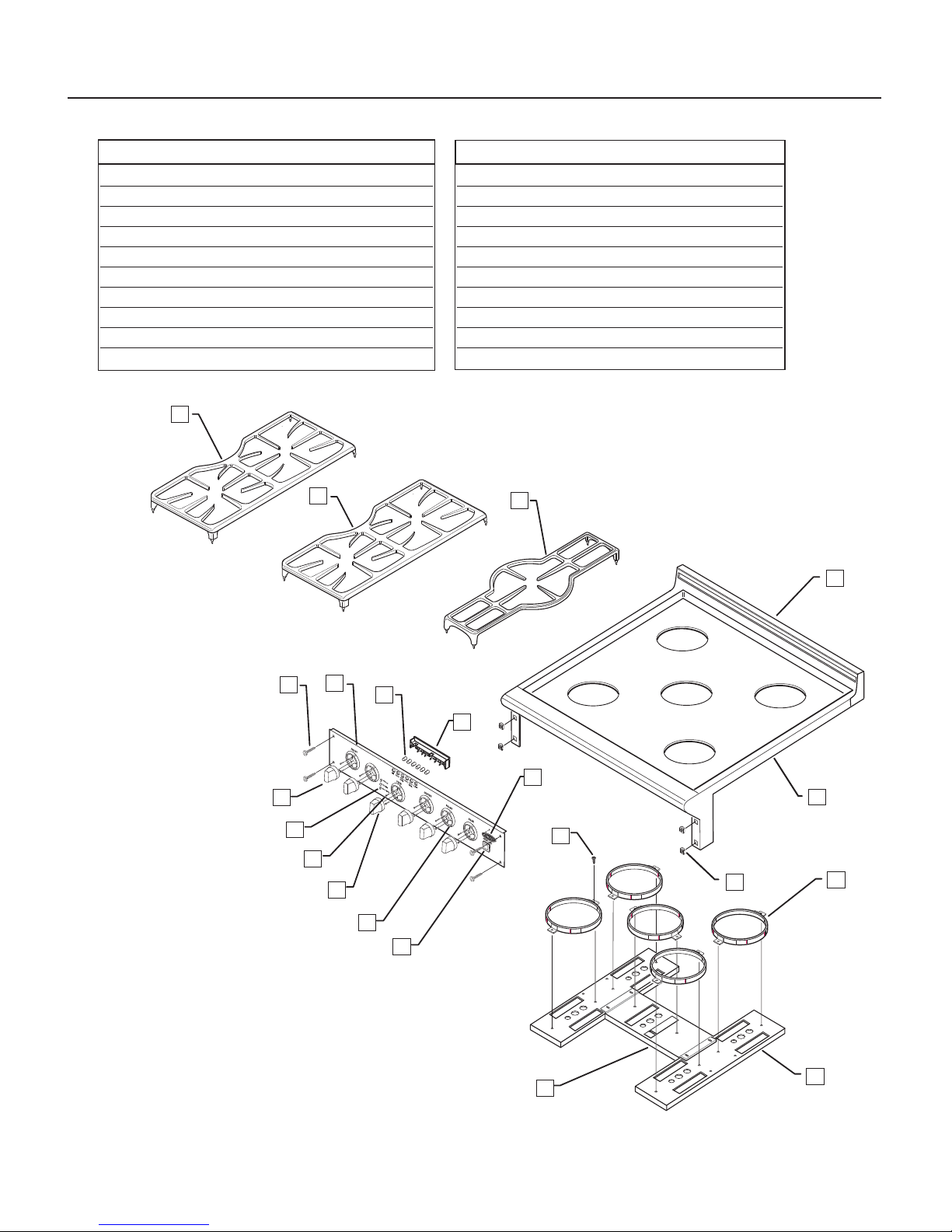
RANGE T OP ASSEMBLY
ITEM PART NO. DESCRIPTION
1 12261-01 SIDE GRATE (R/L)
2 12262-01 CENTER GRATE
3 15002-41 SCREW,TORX (#15) (4 PLCS)
4 14051-01 BUTTON,BLACK (6 PLCS)
5 16399 SWITCH,PUSH BUT TON
6 14307 KNOB,BLACK (5 PLCS)
7 16046-02 LENS,LIGHT PILOT (3 PLCS)
8 15001-29 SCREW,BEZEL (12 PLCS)
9 14306 KNOB,BLACK THERMOSTAT
10 14006-PL BEZEL,PLATED (6 PLCS)
ITEM PART NO. DESCRIPTION
11 16127 SWITCH,OVEN LIGHT
12 15073 LOGO,DCS
13 15001-19 SCREW (10 PLCS)
14 91228 CTR HANGER BURNER
15 91227 HANGER,BURNER (R/L)
16 91727 SUPPORT,COOKTOP (5 PLCS)
17 15029-02 NUT,CAGED (4 PLCS)
18 91782 COOKTOP WLD ASSY,INNER
19 91678 ISLAND TRIM WLD ASSY
20 91224-PA VALVE PANEL ASSY
1
2
3
4
5
6
7
8
9
10
11
12
13
14
15
16
17
18
19
20
1
2
2
R
E
A
R
Page 40
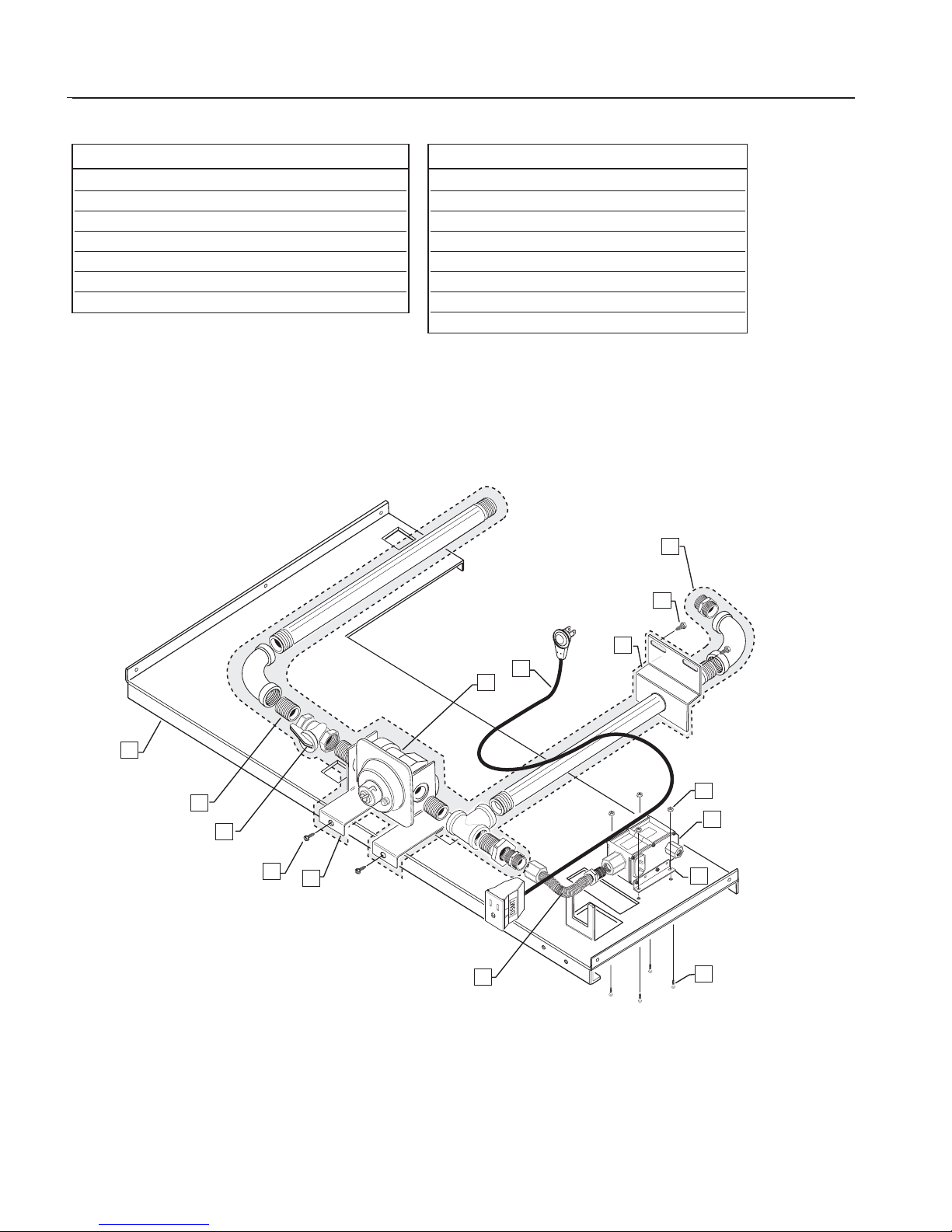
PRELIMINARY
40
SAFETY V ALVE ASSEMBLY
ITEM PART NO. DESCRIPTION
1 91502 SUPPORT,GAS TRAIN
2 18018-1 NIPPLE 1/2 NPT
3 18044 VALVE,SHUT OFF
4 15001-19 SCREW (2 PLCS)
5 91501 BRKT,MOUNT (2 PLCS)
6 15001-19 SCREW (2 PLCS)
7 91851 BRACKET (2 PLCS)
ITEM PART NO. DESCRIPTION
8 13053 VALVE,SAFETY
9 15021-04 NUT
10 16430 CORD,POWER
11 13003 REGULATOR
12 91964 BRACKET
13 15001-19 SCREW (2 PLCS)
14 91938 GAS TRAIN ASSY
15 18379 TUBE,FITTING ASSY
1
2
4
5
10
13
14
12
9
8
6
7
3
11
15
Page 41

PRELIMINARY
41
INFRARED BROILER ASSEMBLY
ITEM PART NUMBER DESCRIPTION
ITEM PART NUMBER DESCRIPTION
1 91242 IR BURNER ASSEMBLY
2 91708 SPACER,AIR BROILER
3 91728-01 INSULATION
4 91245 PLATE,FRONT INSULATION BOX
5 15001-03 SCREW
6 15001-03 SCREW
7 91471 BRACKET,BROILER IGNITER
8 91730-02 INSULATION PANEL
9 91701 DEFLECTOR,LOCK MOTOR
10 15001-03 SCREW
11 91706 SHIELD,BROILER FRONT
12 13043 HI-TEMP CUTOUT
13 91195-PC ACCESS PANEL
14 15001-14 SCREW
15 15001-09 SCREW
16 15001-03 SCREW
17 15001-03 SCREW
18 15001-03 SCREW
19 15001-05 SCREW
20 91481 LOCK BOX, INNER WALL
21 15001-03 SCREW
22 18020-1 FITTING ELBOW
23 18077-2 FERRULE
1
2
3
4
5
6
7
8
9
10
11
12
13
14
15
16
17
18
19
20
21
22
23
Page 42
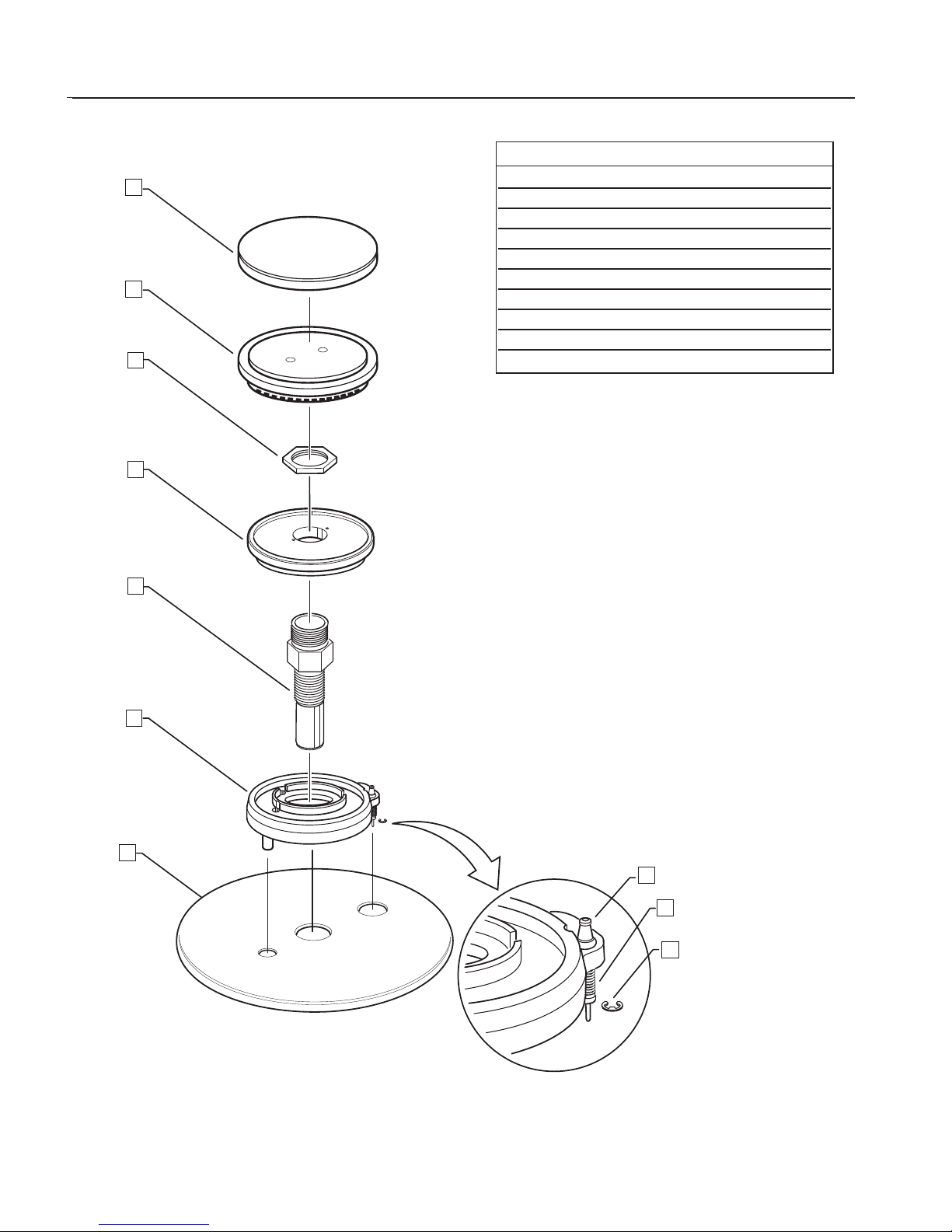
PRELIMINARY
42
SEALED BURNER ASSEMBLY
ITEM PART NO. DESCRIPTION
1 12272 BURNER CAP
2 12274 RING C PORT
3 15219 VENTURI NUT
4 12270 RING C SIMMER
5 13378 VENTURI
6 12304 C BURNER BASE
7 91545-PC VULCANO
8 12224 IGNITER
9 12211 SPRING
10 12231 “E”RING
1
2
3
4
5
6
7
8
9
10
Page 43
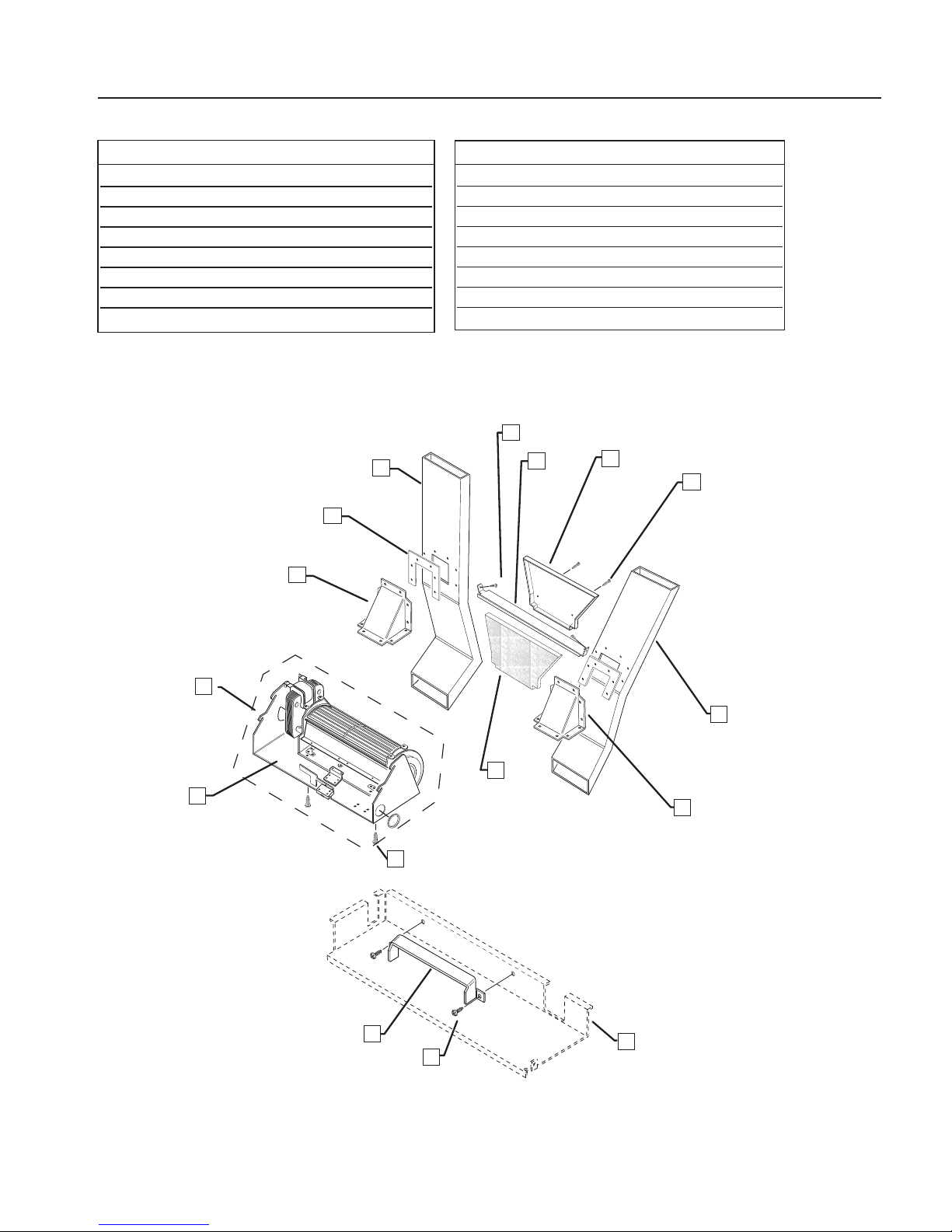
PRELIMINARY
43
COOLING COMPONENTS ASSEMBLY
1
ITEM PART NO. DESCRIPTION
1 91659 COOLING FAN ASSEMBLY
2 91212 BLOWER MOTOR MOUNT
3 15001-12 SCREW (2 PLCS)
4 91701 DEFLECTOR
5 15001-05 SCREW (2 PLCS)
6 91706 SHIELD,BROILER FRONT
7 91707-02 SHIELD EXHAUST TOP (LEFT)
8 91520-02 FLUE VENT L/H
ITEM PART NO. DESCRIPTION
9 91728-02 INSULATION,REAR PANEL
10 91707-01 SHIELD EXHAUST TOP (RIGHT)
11 91730-05 GASKET (2 PLCS)
12 91520-01 FLUE VENT R/H
13 91696 BACK SHIELD
14 91693 RETAINER,INSULATION
15 15001-32 SCREW (2 PLCS)
16 15001-32 SCREW (2 PLCS)
2
3
4
5
6
7
8
9
10
12
11
13
14
15
16
6
Page 44
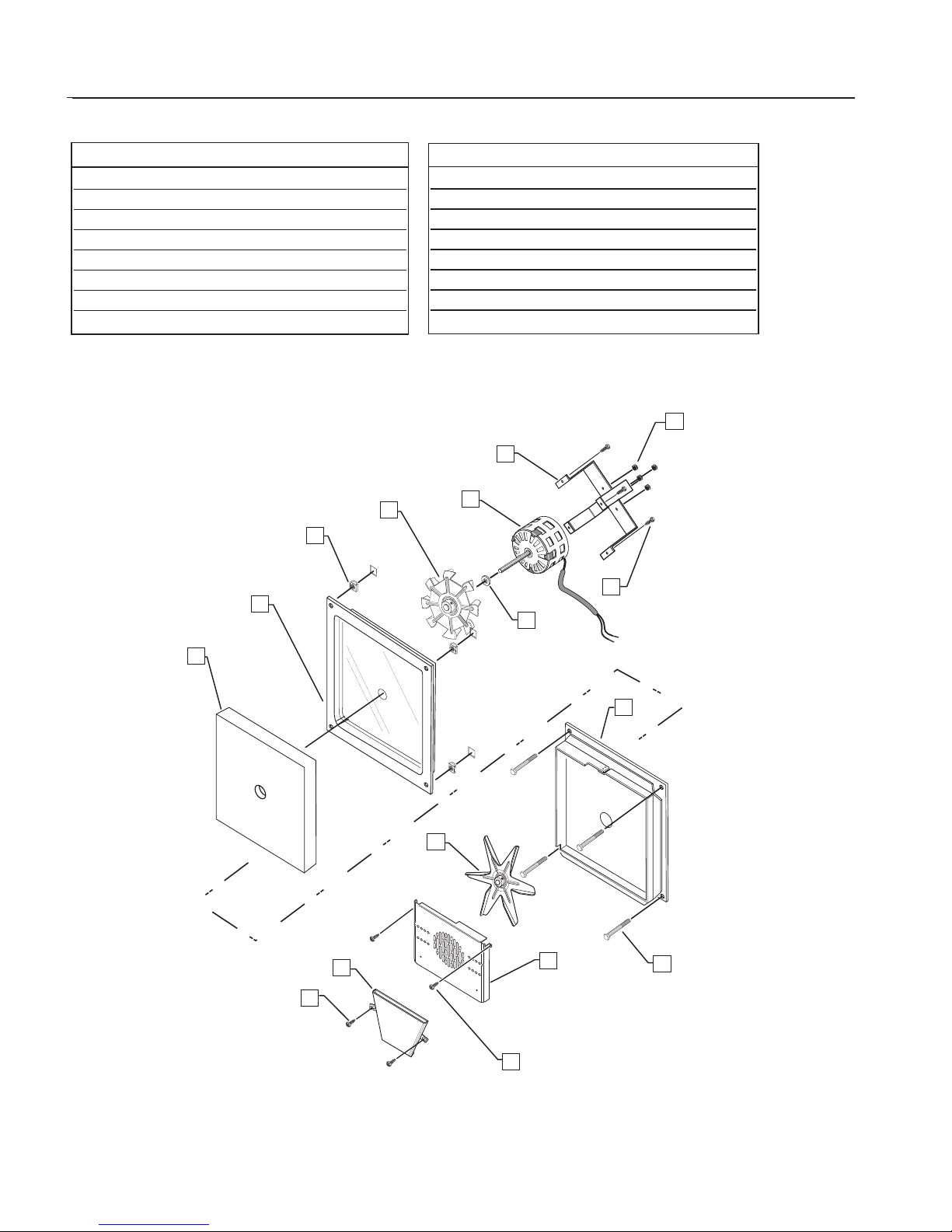
PRELIMINARY
44
CONVECTION ASSEMBLY
ITEM PART NO. DESCRIPTION
1 90276 MOTOR SUPPORT BRACKET
2 16327 CONVECTION FAN MOTOR
3 16053 MOTOR COOLING BLADE
4 15029-02 CAGED NUT
5 91700 WLDMT,INSUL MOTOR COVER
6 90170 PAD INSULATION, MOTOR
7 15001-32 SCREW (2 PLCS)
8 91218-PC OVEN DAMPER
ITEM PART NO. DESCRIPTION
9 15001-32 SCREW (2 PLCS)
10 91214-PC BAFFLE,OVEN
11 16130 CONVECTION BLADE
12 15003-24 BOLT (4 PLCS)
13 90171 INNER WLDMT MOTOR CVR.
14 15005-28 WASHER
15 15001-19 SCREW (4 PLCS)
16 15004-10 NUT,NYLOK (4 PLCS)
1
2
3
4
5
6
7
8
9
10
11
12
13
14
15
16
Page 45
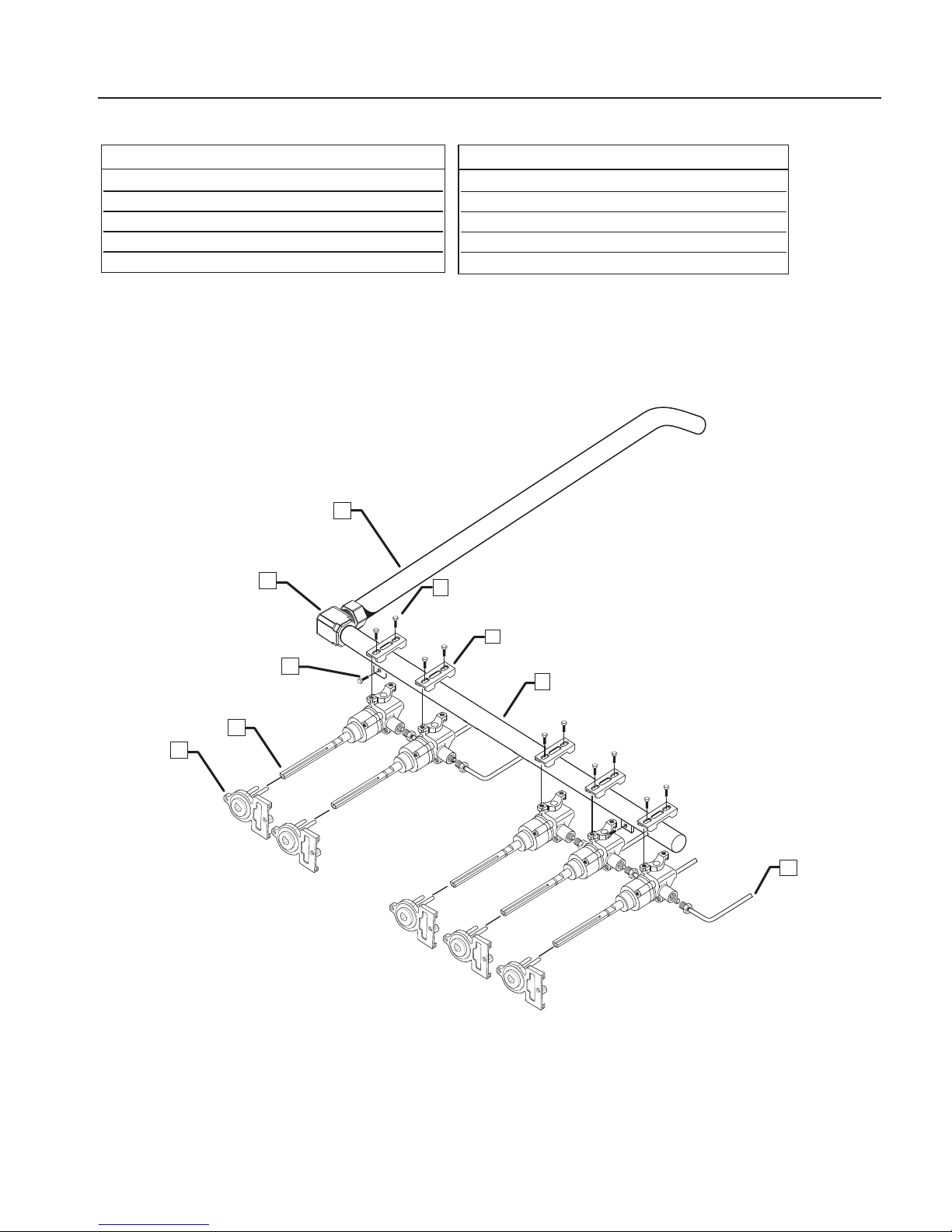
PRELIMINARY
45
MANIFOLD/VALVES ASSEMBLY
ITEM PART NO. DESCRIPTION
1 91724 TUBE (GAS)
2 18480 ELBOW 90º 1/2 NPT TO 5/8 TUBE
3 15021-08 NUT (2 PLCS)
4 13390-06 GAS VALVE,NAT
13390-08 GAS VALVE ,LP
ITEM PART NO. DESCRIPTION
5 16415 SWITCH,IGNITER (5 PLCS)
6 11252 3/16”TUBE ASSY SIMMER REAR
7 18323 MANIFOLD
8 12177 CLAMP,VALVE
9 15003-33 BOLT (10 PLCS)
1
2
3
4
9
8
7
6
5
Page 46
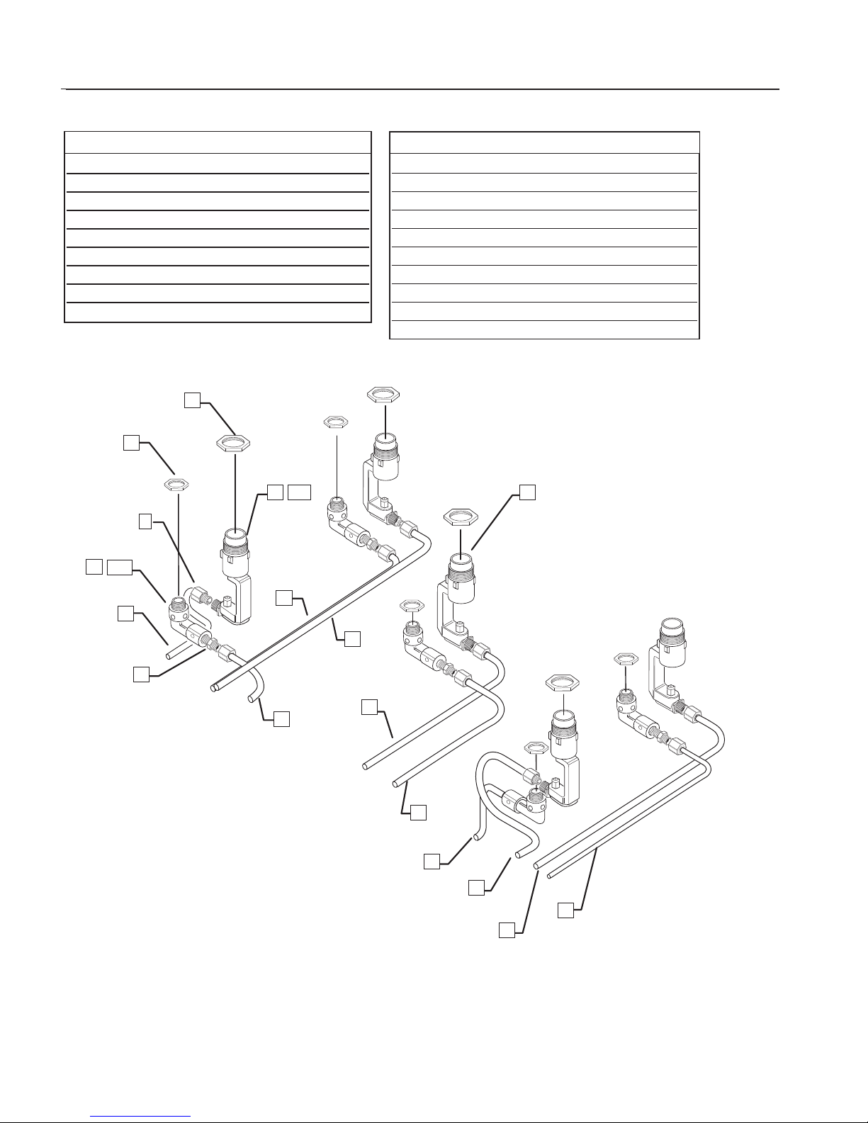
PRELIMINARY
46
GAS JET ASSEMBLIES
ITEM PART NO. DESCRIPTION
1 15219 NUT,VENTURI (5 PLCS)
2 18077-1 NUT, COMPRESSION (MAIN)(5)
3 18284 B-NUT 3/16”(SIMMER)(5 PLCS)
4 11252 TUBE SIMMER (LEFT REAR)
5 11247 TUBE, MAIN (LEFT FRONT)
6 11251 TUBE SIMMER (LEFT FRONT)
7 11248 TUBE, MAIN (LEFT REAR)
8 11249 TUBE, MAIN (CENTER)
9 11253 TUBE SIMMER (CENTER)
ITEM PART NO. DESCRIPTION
10 11251 TUBE SIMMER (RIGHT FRONT)
11 11247 TUBE,MAIN (RIGHT FRONT)
12 11248 TUBE,MAIN (RIGHT REAR)
13 11252 TUBE SIMMER (RIGHT REAR)
14 12200-09 JET HLDR, MAIN (NAT)(CTR)
15 12200-10 JET HLDR, MAIN (NAT)(4 PLCS)
15A 12254-04 JET HLDR,MAIN (LP)(5 PLCS)
16 12254-05 JET HLDR, SIMMER (NAT)(5 PLCS)
16A 12254-04 JET HLDR,SIMMER (LP)(5 PLCS)
17 15236 NUT,W/CHAMPER
1
15
2
16A
5
4
7
6
3
14
8
9
10
11
12
13
16
15A
17
Page 47
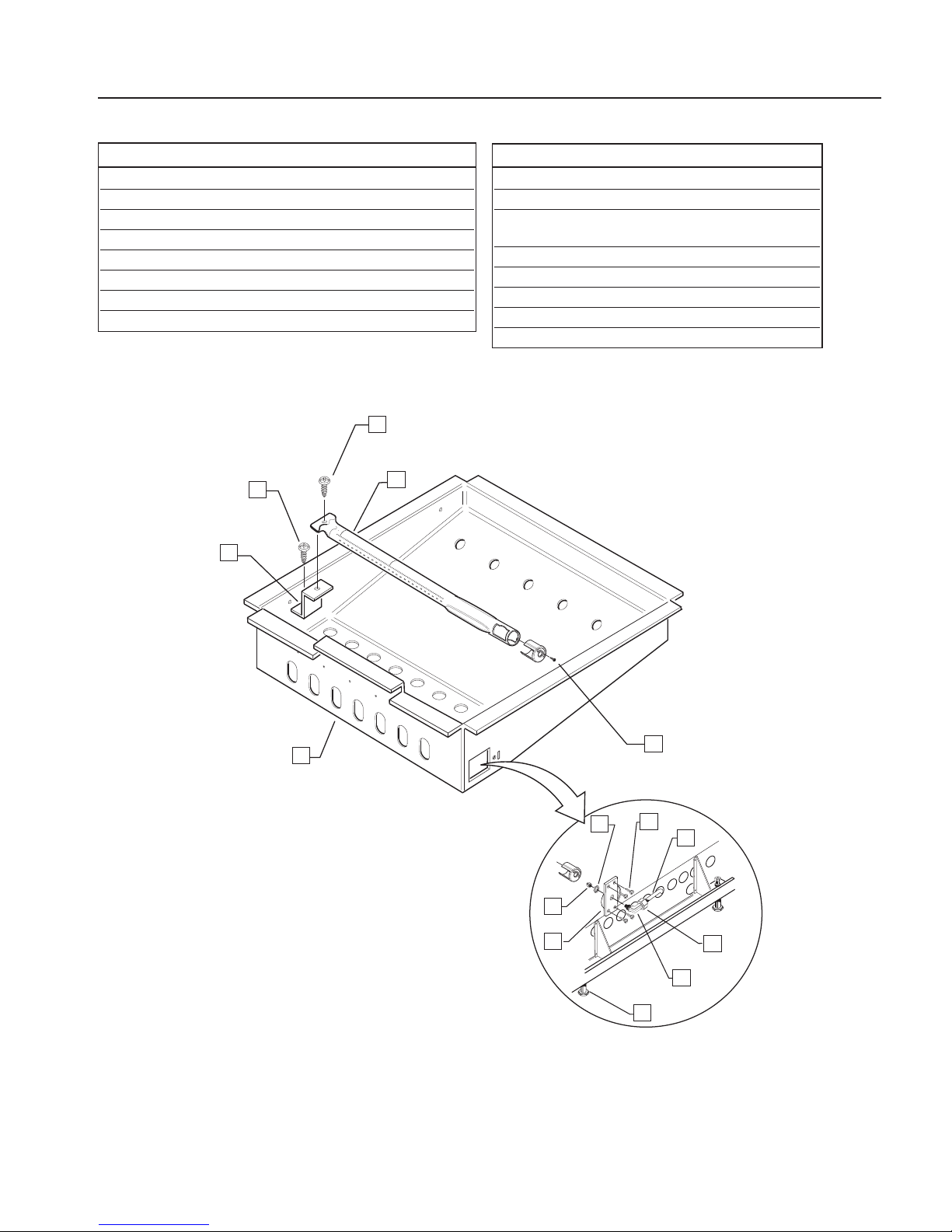
PRELIMINARY
47
OVEN BURNER ASSEMBLY
ITEM PART NO. DESCRIPTION
1 15001-09 SCREW
2 91757 BRACKET,BURNER
3 91937 BURNER BOX
4 91712 BRACKET
5 18052-2 ADJUSTABLE LEG
6 18376-01 90ºELBOW ORIFICE HOLDER ASSY-NAT
18376-02 90ºELBOW ORIFICE HOLDER ASSY-LP
7 18077-1 COMPRESSION NUT
ITEM PART NO. DESCRIPTION
8 91723 TUBE BAKE
9 15001-27 SCREW (4 PLCS)
10 15071 NUT,STAMPED PAL NUT
REPLACEMENT PART
11 15001-09 SCREW
12 12275 BURNER/AIR SHUT TER, OVEN
13 15001-27 SCREW
14 13005-40 ORIFICE (NAT)
13005-53 ORIFICE (LP)
11
13
12
1
2
3
10
9
8
7
6
4
5
14
VIEW LOOKING BEHIND RIGHT SIDE
PANEL NEAR BOTTOM.
Page 48
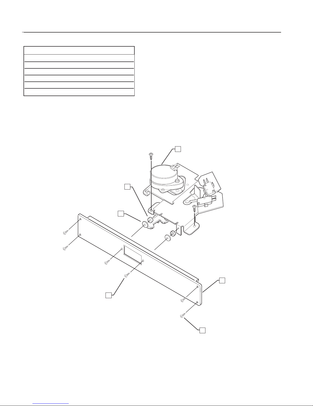
PRELIMINARY
48
MOTORIZED LATCH ASSEMBLY
ITEM PART NO. DESCRIPTION
1 16247 LATCH ASSEMBLY
2 15075-01 SPACER (2 PLCS)(.25 IN.)
3 15005-21 WASHER,MICA (2PLCS)
4 15001-09 SCREW,BLK (2 PLCS)
5 15001-14 SCREW (2 PLCS)
6 91195-PC ACCESS PANEL,PORC.
1
2
3
4
5
6
Page 49
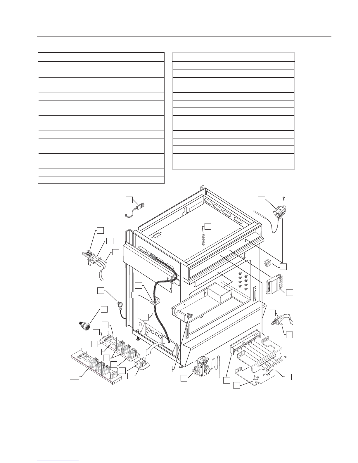
PRELIMINARY
49
ELECTRICAL ASSEMBLY
ITEM PART NO. DESCRIPTION
1 11238 GRMTS, IGN,WIRE (5 PLCS)
2 16046-02 PILOT LIGHT ASSY (5)
3 16009-1 BROIL IGNITER ASSY
4 91244 IGNITER BRACKET
5 15001-03 SCREW (2 PLCS)
6 16430 CORD,POWER RIGHT ANGLE
7 14197 GROMMET
8 50097 BRACKET,HARNESS
9 16242 OVEN LIGHT ASSEMBLY (2)
10 14304-03 WIRE HARNESS
11 15001-31 SCREW
12 91509 ELEC.COMPONENTS BRACKET
12A 91509 (NEW) ELEC.COMPONENTS
BRACKET
13 16352 TERMINAL BLOCK
14 16044-2 CLEAN TIMER
ITEM PART NO. DESCRIPTION
15 16045-3 RELAY (2)
16 16045-2 RELAY
17 15001-19 SCREW (2 PLCS)
18 16464 TRANFORMER
19 13043 HI TEMP CUT OUT
20 13380 THERMOSTAT ASSEMBLY
21 16399 6 PUSH BUTTON SWITCH
22 16041 BLOWER THERMOSTAT
23 91243 BRACKET,SUB PANEL
24 15002-18 SCREW (2 PLCS)
25 16505 OVEN IGNITER ASSY
26 16458 5 BURNER MODULE
27 16127 OVEN IGNITER SWITCH
28 13233 LOCK THERMOSTAT
12A
12
1
2
3
4
5
6
7
8
9
10
11
13
14
15
16
17
18
19
20
21
22
23
24
25
26
27
28
EARLY MODELSNEWER MODELS
Page 50
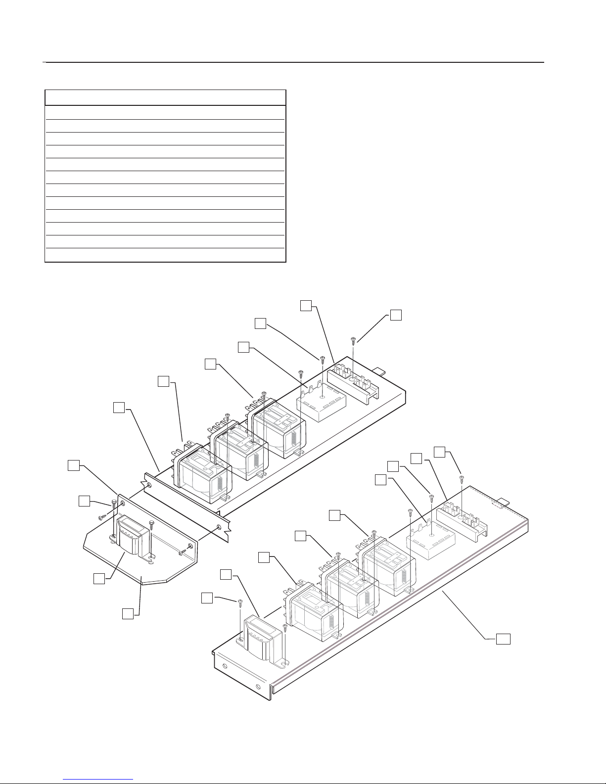
PRELIMINARY
50
ITEM PART NO. DESCRIPTION
1 15001-31 SCREW
2 16352 TERMINAL BLOCK
3 15001-31 SCREW (2 PLCS)
4 16044-2 CLEAN TIMER
5 16045-3 RELAY (2 PLCS)
6 16045-2 RELAY
7 91509 ELEC. COMPONENTS BRACKET
7A 91509 (NEW) ELEC. COMPONENTS BRACKET
8 15001-19 SCREW (2PLCS)
9 15001-41 SCREW
10 16464 TRANSFORMER
11 91711 TRANSFORMER BRACKET
LOWER ELECTRICAL ASSEMBLY
1
2
3
4
5
6
7
8
9
10
11
7A
1
2
1
4
5
5
6
10
9
EARLY MODELS
NEWER MODELS
Page 51
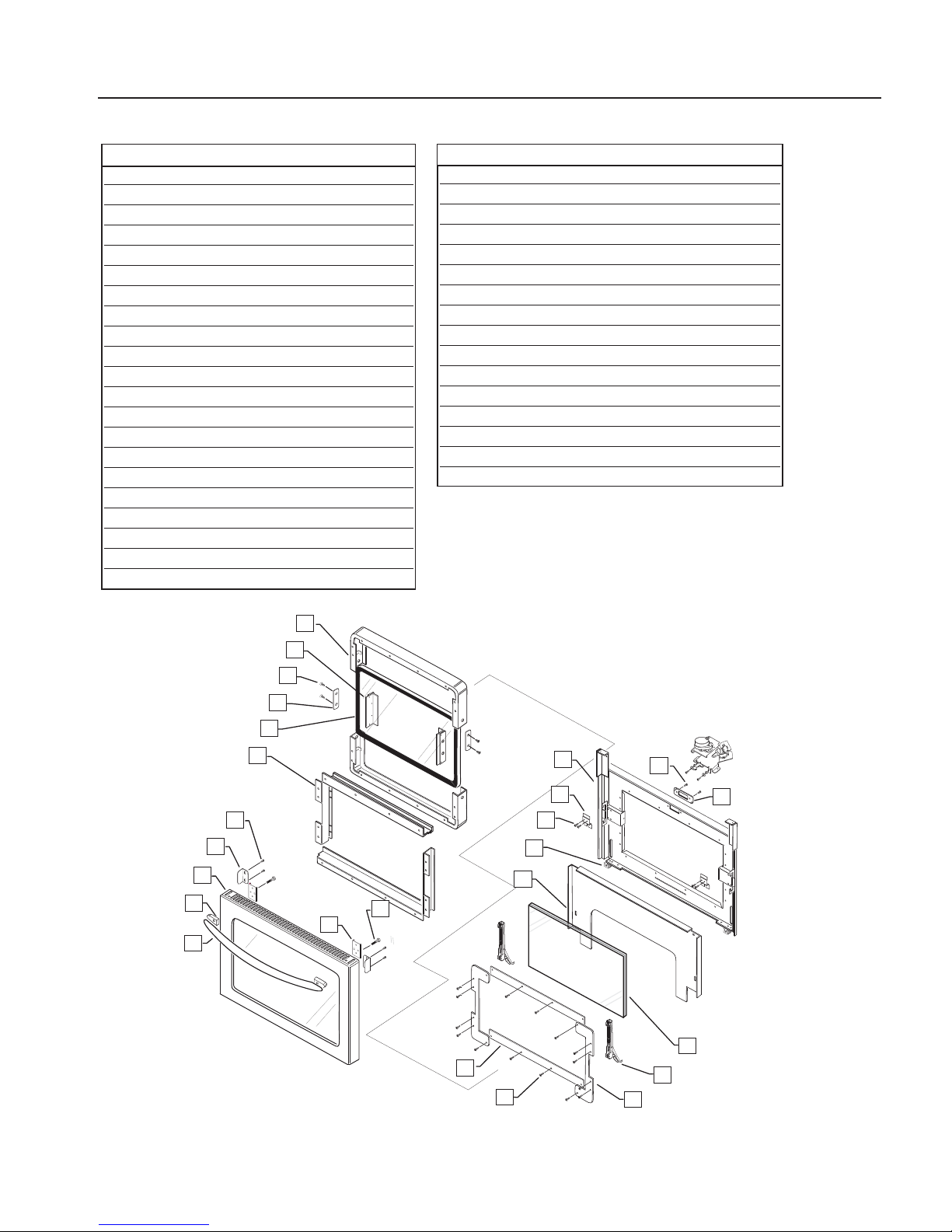
PRELIMINARY
51
DOOR ASSEMBLY
ITEM PART NUMBER DESCRIPTION
* DOOR ASSEMBLIES:
91687 • STAINLESS STEEL
91687-01 • WHITE
91687-02 • BLACK
1 91532 SEAL DOOR UPPER
2 96168 SPACER, SEAL CHANNEL
3 15002-43 SCREW (4 PLCS)
4 96166 COVER,DOOR SEAL
5 14296-01 INSIDE DOOR GLASS
6 91533 DOOR INSULATION COVER
7 15001-13 SCREW
8 91694 SHIELD,DOOR,TOP
9 91528-01/-03 DOOR SKIN
* (PRO/PSH) DOOR SKIN NO LOGO:
91529-01-PA • STAINLESS STEEL
91529-03-PA • WHITE
91529-04-PA • BLACK
* DOOR SKIN,EURO
92032-01 • STAINLESS STEEL
92032-02 • WHITE
92032-03 • BLACK
10 12167 SPACER (2 PLCS)(BRT CHROME)
11 12239 DOOR HANDLE
12 96012 HANDLE STIFFENER (2 PLCS)
13 15002-47 BOLT,1/4-28 UNF-2AX1.25GDS(4)
14 91530 COVER GLASS TOP/BOTTOM
15 15001-14 SCREW (16 PLCS)
16 91531 COVER GLASS SIDES (2 PLCS)
17 150034-1 DOOR HINGE
18 14297-01 INNER DOOR GLASS
19 91536 DOOR HEAT SHIELD
20 96021 HINGE BOTTOM PLATE
21 15001-09 SCREW (4 PLCS)
22 91524 HINGE TOP BRACKET
23 91655-PC LINER,DOOR WLDMT
24 15001-09 SCREW (2 PLCS)
25 50046-1 LATCH PLATE-30
ITEM PART NUMBER DESCRIPTION
* Items not shown
1
2
3
4
5
6
7
8
9
10
12
11
13
23
22
21
20
19
24
25
14
15
18
17
16
Page 52
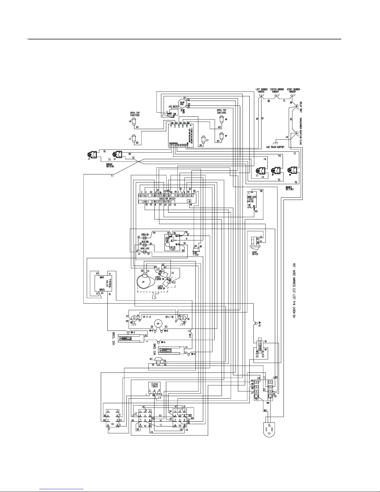
PRELIMINARY
52
WIRING DIAGRAM
Page 53
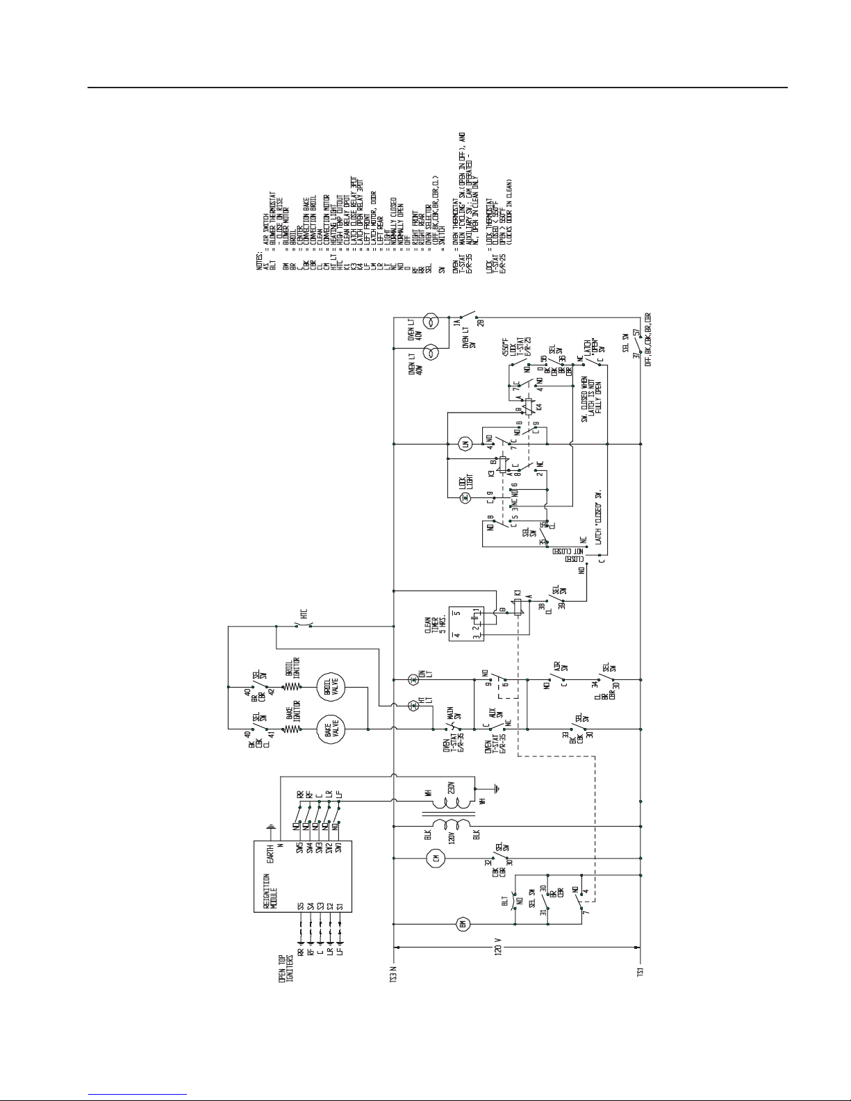
PRELIMINARY
53
WIRING SCHEMATIC
Page 54

PRELIMINARY
54
SERVICE
For warranty service,please contact your local service provider or DCS Customer Care Center at (888) 281-5698,Monday
thru Friday, 6:00 am – 4:30 pm PST. Before you call,please have the following information ready:
Model Number
Serial Number
Date of installation
A brief description of the problem
Your satisfaction is of the utmost importance to us.If a problem cannot be resolved to your satisfaction,please write or
fax us at:
Write:
DCS
Attention:Customer Care Center
5800 Skylab Road
Huntington Beach,CA 92647
email: [email protected]
Page 55

PRELIMINARY
55
WARRANTY
Length of Warranty :
One (1) Year Full parts and Labor Covers the entire product.
Five ( 5 ) Year Sur face burners,O ven burner.
Ten (10) Years Limited Porcelain oven,Porcelain inner door panel.
DCS Will Pay For
All repair labor and parts found to be defective due to materials or workmanship for one full year “IN HOME”warranty
during the first year of ownership. This does not apply if the unit was subjected to other than normal household use.
Service must be provided by an Authorized Factory Agent during normal working hours. No charges will be made for
repair or replacement at the location of initial installation or factory for parts returned pre-paid,through the dealer and
claimed within the warranty period,and found by DCS to be defective.
Replacement will be F.O.B.DCS, and DCS will not be liable for any transportation costs,labor costs,or export duties. This
warranty shall not apply, nor can we assume responsibility for damage that might result from failure to follow
manufactures instructions or local codes,where the appliance has been tampered with or altered in anyway or which,in
our judgement, has been subjected to misuse, negligence, or accident. Implied warranty shall not extend beyond the
duration of this written warranty. This warranty is in lieu of all warranties expressed or implied and all other obligations
or liability in connection with the sale of this appliance.
DCS Will Not Pay For
Installation or start-up.
Shipping damage.
Service by an unauthorized agency.
Damage or repairs due to service by an unauthorized agency or the use of unauthorized parts.
Service during other than normal working hours.
Improper installation,such as improper hook-up,etc.
Service visits to teach you how to use the appliance;correct the installation;reset circuit breakers or replace home
fuses.
Repairs due to other than normal household use.
Damage caused from accident,abuse,alteration,misuse,incorrect installation or installation not in accordance with
local codes.
Units installed in non-residential application such as day care centers,bed and breakfast centers,churches,nursing
homes,restaurants,hotels,schools,etc.
This warranty applies to appliances used in residential applications;it does not cover their use in commercial situations.
This warranty is for products purchased and retained in the 50 states of the U.S.A.,the District of Columbia and Canada.
This warranty applies even if you should move during the warranty period. Should the appliance be sold by the original
purchaser during the warranty period,the new owner continues to be protected until the expiration date of the original
purchaser’s warranty period. This warranty gives you specific legal rights.You may also have other rights which vary from
state to state.
Page 56

NOTES
56
PRELIMINARY
Page 57

5800 Skylab Road,Huntington Beach, CA 92647
Tel:714.372.7000 • Fax:714.372.7001
Customer Service:(888) 281-5698
www.dcsappliances.com
As product improvement is an ongoing process at DCS, we
reserve the right to change specifications or design without
notice.
P/N 17559 Rev.A
Litho in USA 07/2003
Page 58
30”FIVE BURNER
SELF CLEANING GAS RANGE
Service Manual
MODELS:
RGSC-305SS
RGSC-305BK
RGSC-305WT
 Loading...