

Page 1
OUTDOOR BEER DISPENSERS
Installation, Operation and Maintenance Instructions
DISTRIBUTEURS DE BIÈRE D’EXTÉRIEUR
Instructions d’installation, d’utilisation et d’entretien
MODELS:
MODÈLES:
RF24TR1
RF24TL1
RF24BTR1
RF24BTL1
Page 2
US
CA
CONTENTS
Contents:
Safety information ...............................................................2
Unpacking your appliance ...................................................3
Warranty registration............................................................3
Installing your appliance ......................................................4
Cabinet clearances .........................................................4
Leveling the appliance ....................................................4
Electrical connection ......................................................5
Installing the anti-tip device .................................................6
Product dimensions ............................................................8
Using your Electronic control...............................................9
Starting your appliance....................................................9
Turning your appliance "ON" or "OFF".............................9
Adjusting the temperature................................................9
Beer dispenser operation..................................................9
Alarms............................................................................9
Door ajar......................................................................9
Temperature sensor fault............................................9
High and Low temperature alarms..............................9
Alarm mute......................................................................9
Using your beer dispenser.................................................10
Tap equipment and assembly.......................................10
CO2 regulator.................................................................14
Drain kit..........................................................................15
Care and cleaning ............................................................15
Cleaning the drain sump................................................15
Keg coupler cleaning.....................................................16
Faucet cleaning ............................................................16
Front grille .....................................................................16
Cabinet.........................................................................16
Interior...........................................................................16
Long term storage / winterization .......................................17
Stainless steel maintenance ............................................19
Energy saving tips .............................................................20
Troubleshooting .................................................................21
Obtaining service .............................................................21
Warranty ............................................................................22
Important Safety Instructions
Warnings and safety instructions appearing in this guide
are not meant to cover all possible conditions and situations that may occur. Common sense, caution, and care
must be exercised when installing, maintaining, or operating this appliance.
Recognize Safety Symbols,
Words, and Labels.
!
WARNING
WARNING - You can be killed or seriously injured
if you do not follow these instructions.
!
CAUTION
CAUTION-Hazards or unsafe practices which could re-
sult in personal injury or property / product damage.
NOTE
NOTE-Important information to help assure a problem
free installation and operation.
State of California Proposition 65 Warnings:
WARNING: This product contains one or more chemicals
known to the State of California to cause cancer.
WARNING: This product contains one or more chemicals
known to the State of California to cause birth defects or
other reproductive harm.
2
Page 3
UNPACKING YOUR APPLIANCE
!
WARNING
EXCESSIVE WEIGHT HAZARD
Use two or more people to move product.
Failure to do so can result in personal injury.
US
CA
A Message To Our Customers
Thank you for selecting this DCS Outdoor Refrigerator.
Because of this appliances’ unique features we have developed this Use and Care and Installation Guide. It contains
valuable information on how to properly install, operate and
maintain your new appliance for years of safe and enjoyable operation.
Remove Interior Packaging
Your appliance has been packed for shipment with all parts
that could be damaged by movement securely fastened.
Remove internal packing materials and any tape holding internal components in place. The owners manual is shipped
inside the product in a plastic bag along with the warranty
registration card, and other accessory items.
Important
Keep your carton and packaging until your appliance has
been thoroughly inspected and found to be in good condition. If there is damage, the packaging will be needed as
proof of damage in transit. Afterwards please dispose of all
items responsibly.
!
WARNING
WARNING - Dispose of the plastic bags which can
be a suffocation hazard.
Note to Customer
This merchandise was carefully packed and thoroughly
inspected before leaving our plant. Responsibility for its
safe delivery was assumed by the retailer upon acceptance
of the shipment. Claims for loss or damage sustained in
transit must be made to the retailer.
For your convenience, product questions can be answered
by a DCS Customer Care Representative at
1-888-936-7872, or email: customer.care@sherpaykel.com
NOTE: Please write the Model, Code, and Serial Number
on this page for references (the serial plate is located on
the upper left side, inner wall).
MODEL NUMBER:
CODE:
SERIAL NUMBER:
NOTE: Inspect the product to verify that there is no shipping damage. If any damage is detected, call the shipper
and initiate a damage claim. DCS by Fisher & Paykel is not
responsible for shipping damage.
DO NOT discard any packing material (box, pallet, straps)
until the unit has been inspected.
!
WARNING
WARNING - Help Prevent Tragedies
Child entrapment and suffocation are not problems of
the past. Junked or abandoned refrigerators are still
dangerous - even if they sit out for "just a few hours".
NOTE
DO NOT RETURN DAMAGED MERCHANDISE TO THE
MANUFACTURER - FILE THE CLAIM WITH THE
RETAILER.
!
CAUTION
If the appliance was shipped, handled, or stored in other
than an upright position for any period of time, allow the appliance to sit upright for a period of at least 24 hours before
plugging in. This will assure oil returns to the compressor.
Plugging the appliance in immediately may cause damage
to internal parts.
If you are getting rid of your old refrigerator, please
follow the instructions below to help prevent accidents.
Before you throw away your old refrigerator or
freezer:
• Take off the doors or remove the drawers.
• Leave the shelves in place so children may not
easily climb inside.
3
Page 4
US
CA
INSTALLING YOUR APPLIANCE
Select Location
The proper location will ensure peak performance of your
appliance. We recommend a location where the unit will
be out of direct sunlight and away from heat sources. To
ensure your product performs to specications, the recommended installation location temperature range is from
55 to 115°F (13 to 46°C).
Cabinet Clearance
Ventilation is required from the bottom front of the appliance. Keep this area open and clear of any obstructions.
Adjacent cabinets and counter top can be installed around
the appliance as long as the front grille remains unobstructed.
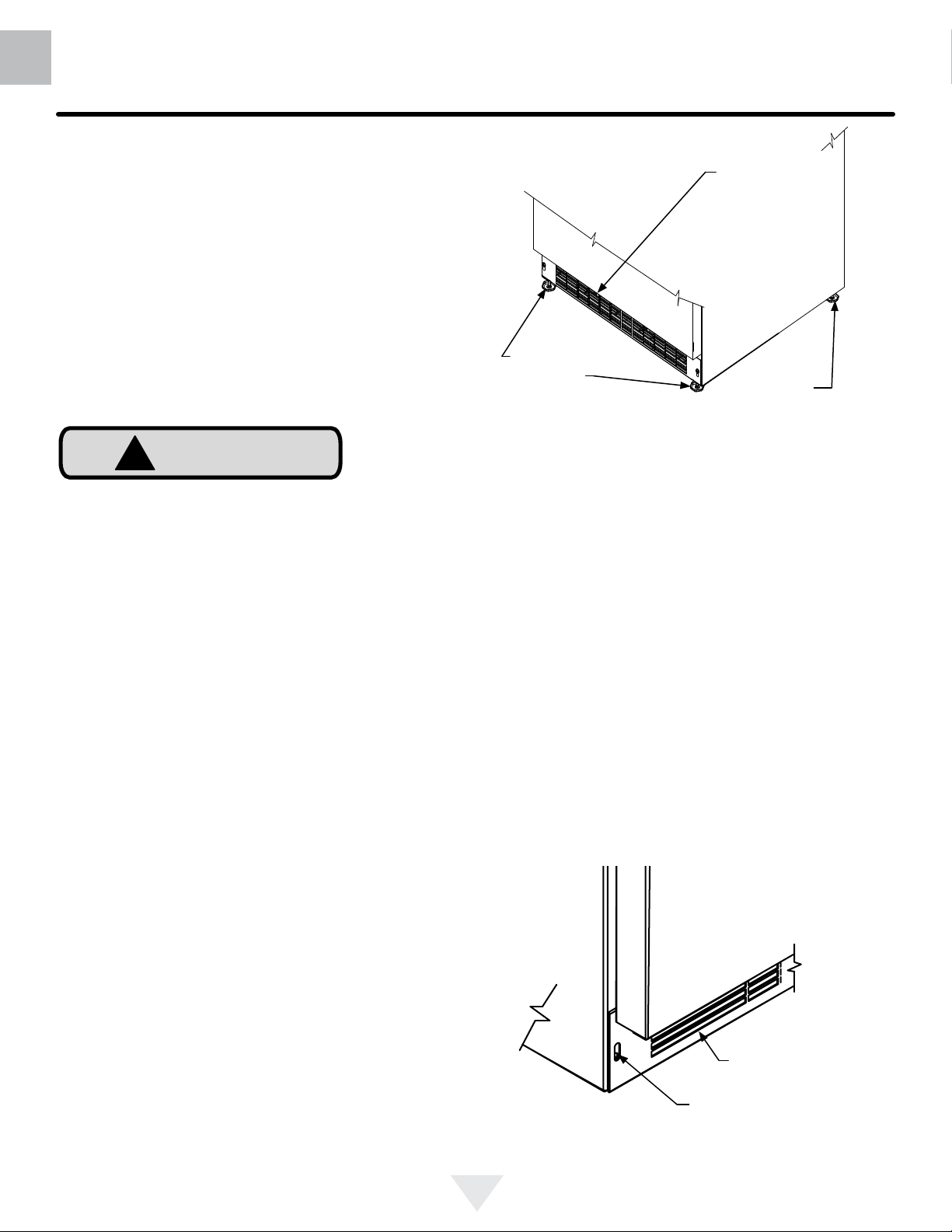
Front Leveling
Legs
Figure 1
Front Grille,
keep this area
open.
Rear
Leveling
Legs
!
CAUTION
Front Grille
Do not obstruct the front grille. The openings within the
front grille allow air to ow through the condenser heat exchanger. Restrictions to this air ow will result in increased
energy usage and loss of cooling capacity. For this reason
it is important this area not be obstructed and the grille
openings kept clean (See Figure 1). The use of a custom
made grille is not recommended as it may restrict air ow.
Leveling Legs
Adjustable legs at the front and rear corners of the appli-
ance should be set so the unit is rmly positioned on the
oor and level from side to side and front to back. The
overall height of your appliance may be adjusted between
the minimum, 333⁄4" (85.7 cm), by turning the leveling leg in
(CW ↷) and the maximum, 343⁄4" (88.3 cm) by turning the
leveling leg out (CCW ↶).
To adjust the leveling legs, place the appliance on a solid
surface and protect the oor beneath the legs to avoid
scratching the oor. With the assistance of another person,
lean the appliance back to access the front leveling legs.
Raise or lower the legs to the required dimension by turning
the legs. Repeat this process for the rear by tilting the appliance forward using caution. On a level surface check the
appliance for levelness and adjust accordingly.
The front grille screws may be loosened and the grille adjusted to the desired height. When adjustment is complete
tighten the two front grille screws. (See Figure 2).
Front grille
Front grille screw
Figure 2
4
Page 5
INSTALLING YOUR APPLIANCE
US
CA
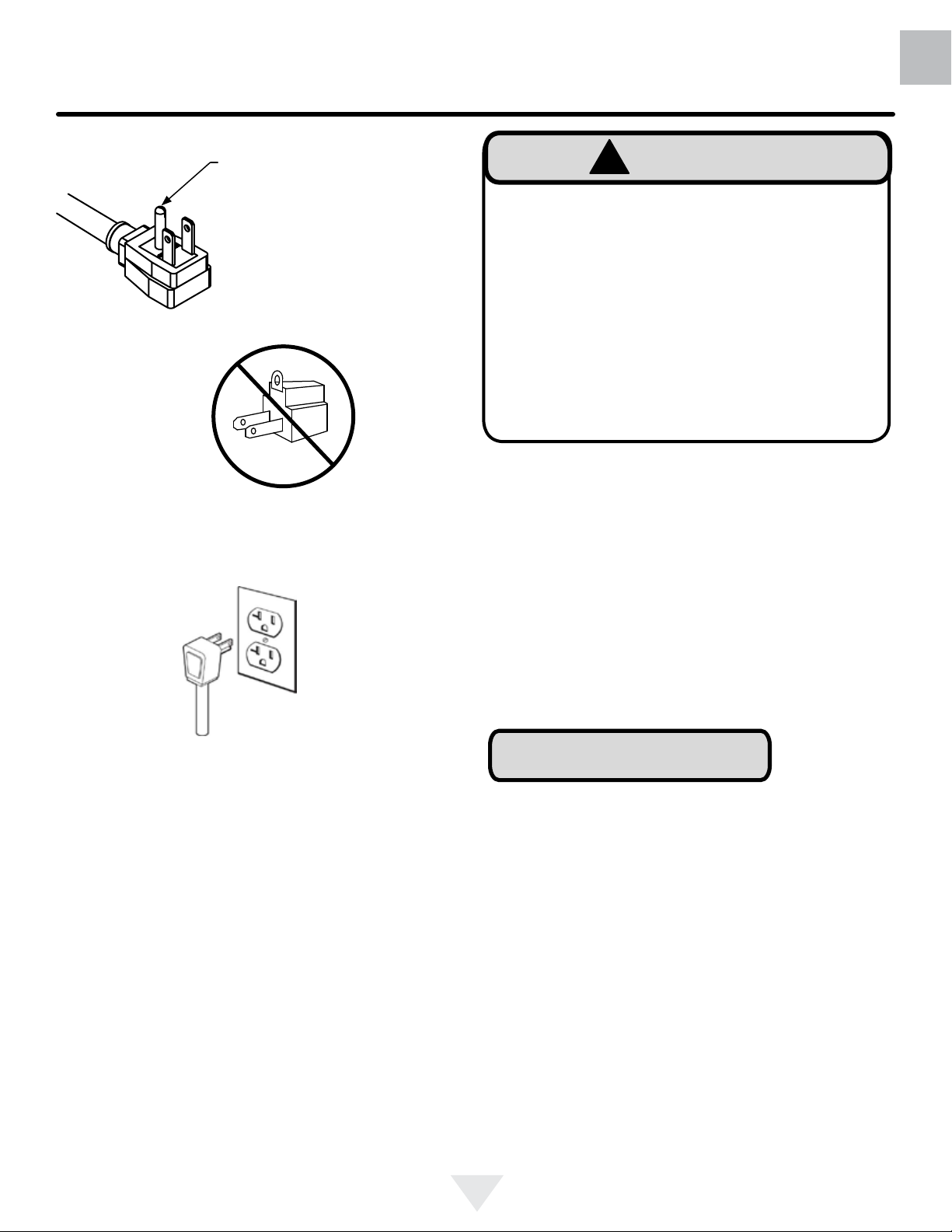
Figure 3
Do not remove
ground prong
Figure 4
!
WARNING
Electrical Shock Hazard
• Do not use an extension cord with this appliance.
They can be hazardous and can degrade product
performance.
• This appliance should not, under any circumstances, be installed to an un-grounded electrical supply.
• Do not remove the grounding prong from the power
cord. (See Figure 3).
• Do not use an adapter. (See Figure 4).
• Do not splash or spray water from a hose on the
appliance. Doing so may cause an electrical shock,
which may result in severe injury or death.
Electrical Connection
A grounded 115 volt, 15 amp dedicated circuit is required.
This product is factory equipped with a power supply
cord that has a three-pronged, grounded plug. It must be
plugged into a mating grounding type receptacle in accordance with the National Electrical Code and applicable local codes and ordinances (see Figure 5). If the circuit does
not have a grounding type receptacle, it is the responsibility
and obligation of the customer to provide the proper power
supply. The third ground prong should not, under any circumstances, be cut or removed.
Figure 5
NOTE
Ground Fault Circuit Interrupters (GFCI) are prone to nuisance tripping which will cause the appliance to shut down.
GFCI’s are generally not used on circuits with power equipment that must run unattended for long periods of time, unless required to meet local building codes and ordinances.
5
Page 6
US
CA
INSTALLING THE ANTI TIP DEVICE
FOR FREESTANDING INSTALLATIONS
!
WARNING
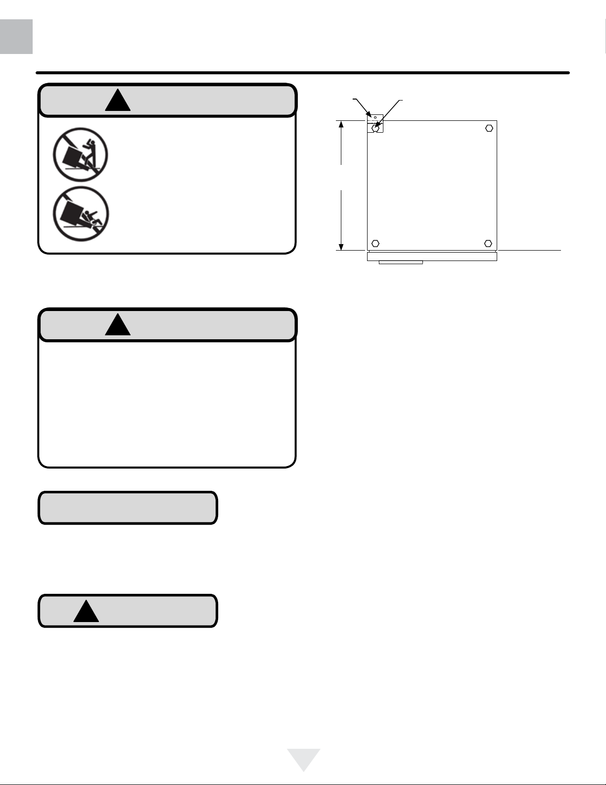
• ALL APPLIANCES CAN TIP
RESULTING IN INJURY.
Anti-Tip
Bracket
Leveling Leg
• INSTALL THE ANTI-TIP
BRACKET PACKED WITH
THE APPLIANCE.
• FOLLOW THE INSTRUCTIONS BELOW
Anti-Tip Device
!
WARNING
If your refrigerator is not located under a counter
top (free standing), you must use an anti-tip device
installed as per these instructions. If the refrigerator is
removed from its location for any reason, make sure
that the device is properly engaged with the anti-tip
bracket when you push the refrigerator back into the
original location. If the device is not properly engaged,
there is a risk of the refrigerator tipping over, with the
potential for property damage or personal injury.
211⁄2"
(54.6 cm)
Bottom View of
Beer dispenser
Front of cabinet
Figure 6
Step by step instructions for locating the
position of the bracket:
1) Decide where you want to place the beer dispenser.
Slide it into place, being careful not to damage the oor,
leaving 1" (2.5 cm) of clearance from the rear wall to allow
room for the anti-tip bracket.
2) Raise the rear leveling legs approximately 1⁄4" (6 mm) to
allow engagement with the anti-tip bracket. Level the unit
by adjusting all the leveling legs as required. Turning the
leveling leg counterclockwise will raise the unit and clockwise will lower the unit.
NOTE
If installing on a concrete oor, concrete fasteners are
required, (not included with the anti-tip kit).
!
CAUTION
Any nished ooring should be protected with appropriate
material to avoid damage when moving the unit.
Floor Mount Installation
The anti-tip bracket is to be located on the oor in the left or
right rear corner of the beer dispenser as shown in
Figure 6.
3) Make sure the beer dispenser is in the desired location,
then mark on the oor the rear and side corner of the cabinet where the anti-tip bracket will be installed. If the installation does not allow marking the rear corner of the cabinet,
then make temporary lines on the oor marking the front
corner of the cabinet, excluding the door. Slide the beer
dispenser out of the way. From the temporary line extend
the sidewall line back 211⁄2" (54.6 cm) as shown in Figure 6.
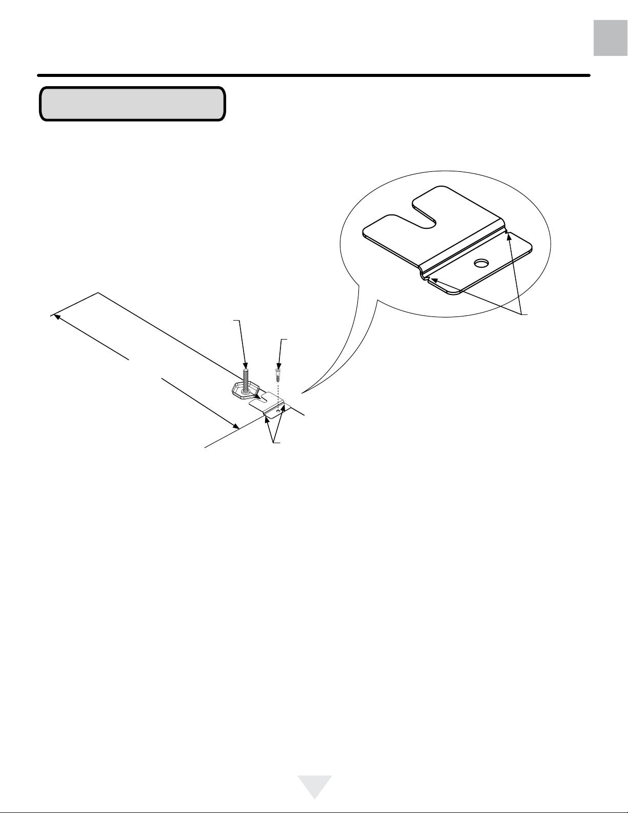
4) Align the anti-tip bracket to the marks on the oor so
the side of the bracket lines up with the side of the cabinet
mark, and the "V" notches on the anti-tip bracket line up
with the end of the 211⁄2" (54.6 cm) line (Rear of cabinet
line).
5) Fasten the anti-tip bracket to the oor using the supplied
screw. (See Figure 7).
6) Slide the cabinet back into position, making sure the rear
cabinet leveling leg slides under the anti-tip bracket engaging the slot.
6
Page 7
INSTALLING THE ANTI TIP DEVICE
FOR FREESTANDING INSTALLATIONS
NOTE
When the oor mounted anti-tip bracket is used the minimum adjusted height of the cabinet is increased by
3
⁄8" (9 mm).
US
CA
Front of cabinet line
Side of cabinet line
211⁄2"
(54.6 cm)
Figure 7
Rear Leveling leg
Rear of cabinet line
Screw
"V" notches
in bracket
Figure 7a
"V" notches
in bracket
7
Page 8
US
CA
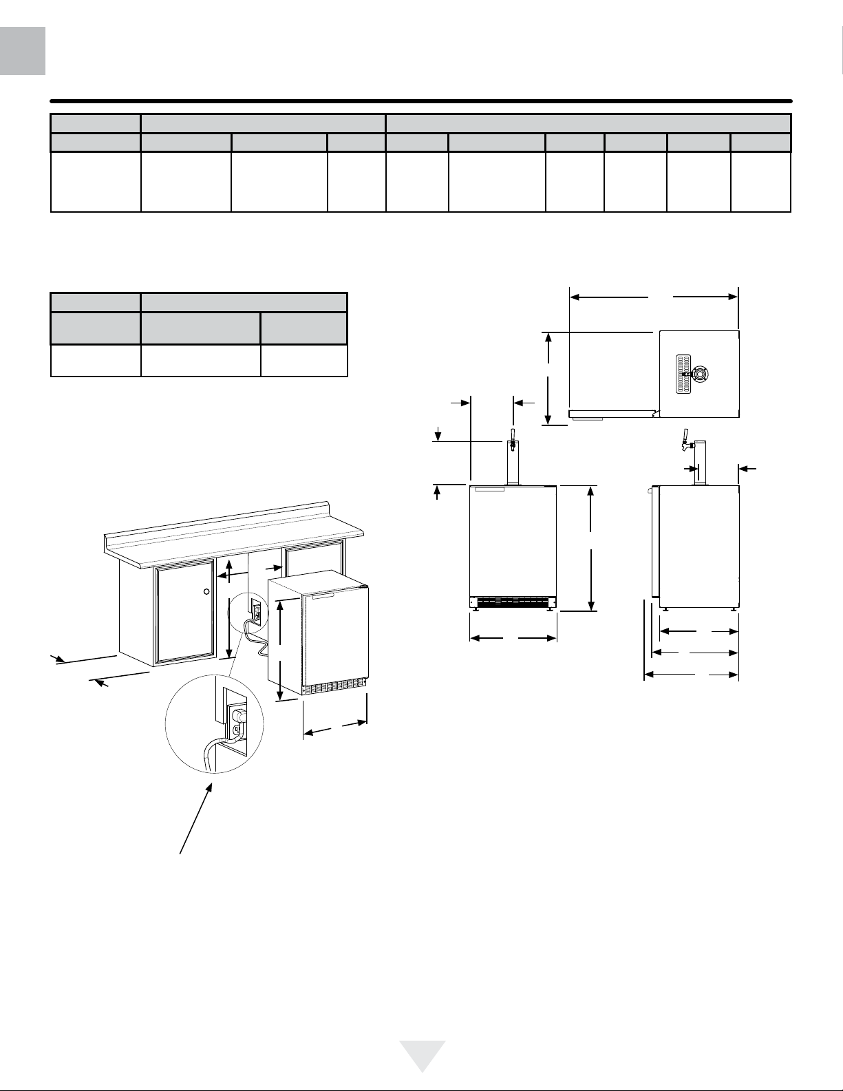
PRODUCT DIMENSIONS
ROUGH-IN OPENING DIMENSIONS CABINET DIMENSIONS
MODEL "A" "B" "C" "D" "E" "F" "G" "H" "J"
1
24
All Models
⁄4" (61.6 cm)
24 ½" (62 cm)
(with optional DCS
side trim kit)
**34" to 35"
(86.4 to 88.9 cm)
*
237⁄8"
(60.7 cm)
333⁄4" to 343⁄4"
(85.7 to 88.3 cm)
2323⁄32"
(60.2 cm)
261⁄4"
(66.7 cm)
4613⁄32"
(117.9 cm)
(66.7 cm)
261⁄4"
PRODUCT DATA
MODEL
All Models 115V/60Hz/15A
"C"
ELECTRICAL
REQUIREMENTS***
"B"
"A"
PRODUCT
WEIGHT
140 lbs
(63.6 kg)
"E"
1115⁄16"
(30.3 cm)
121⁄4"
(31.1 cm)
"D"
"J"
"E"
Figure 9
"H"
11"
(27.9 cm)
211⁄2"
(54.6 cm)
"F"
"G"
"D"
Figure 8
Figure 8a
If necessary to gain clearance inside the rough-in
opening a hole can be cut through the adjacent cabinet and the power cord routed through this hole to a
power outlet. Another way to increase the available
opening depth is to recess the power outlet into the
rear wall to gain the thickness of the power cord plug.
* Depth dimension of rough-in opening may vary depending on each individual installation. To recess entire door "F"
dimension plus 1" (2.5 cm) for thickness of power cord plug
is required.
** Minimum rough-in opening required is to be larger than
the adjusted height of the cabinet.
*** A grounded 15 amp dedicated circuit is required. Follow
all local building codes when installing electrical and appliance.
8
Page 9
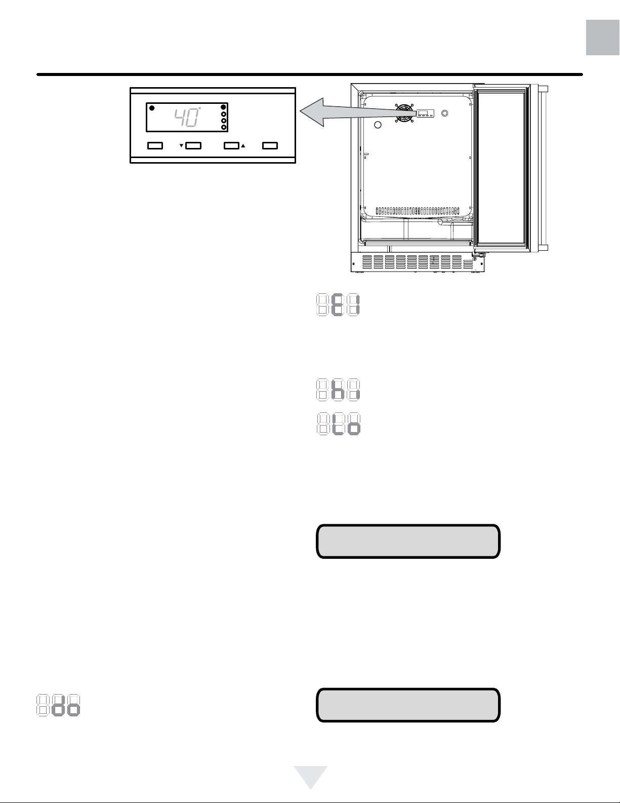
USING YOUR ELECTRONIC CONTROL
Alarm
F
Figure 10
close-up of control
Set
Press and Hold Press and Hold
Starting your beer dispenser
Plug the beer dispenser power cord into a wall outlet. Your
beer dispenser will begin cooling after power is applied.
If your beer dispenser does not start, check that the beer dispenser is turned on and the set temperature is cold enough.
Colder Warmer
ON/OFF
US
CA
Turning your beer dispenser ON or OFF
If the beer dispenser is on, the beer dispenser temperature
will be shown on the display. To turn the beer dispenser
off, press and hold the "ON/OFF" button for three seconds.
"OFF" will appear on the display.
If the beer dispenser is not on, "OFF" will be shown on the
display. To turn the beer dispenser on, press and hold the
"ON/OFF" button for three seconds. The beer dispenser
temperature will be shown on the display.
Set temperature
To set the beer dispenser temperature, press and hold
the "SET" button. When the "SET" button is pressed, the
display will show the set temperature. While holding the
"SET" button, press the "WARMER" or "COLDER" buttons
to adjust set temperature.
Beer dispenser operation
The available temperature range of the beer dispenser is
34 to 46°F (1 to 8°C).
It may take up to 24 hours for your beer dispenser to reach
desired temperature. This will depend on amount of content
loaded and number of door opening and closings.
For best results allow beer dispenser to "pull down" to
desired set temperature before loading. Once contents are
loaded, allow at least 48 hours for temperature to stabilize
before making any adjustments to the set temperature.
Alarms
Your digital display function will monitor beer dispenser
function and alert you with a series of audible and
visual alarms.
panel will ash "do" and the Alarm LED located at the top
left of the display below the word "Alarm" will be illuminated. This will stop as soon as the door is closed.
• Door Ajar Alarm: If the door has been left
open for over ve minutes, the alarm will
sound in one second intervals. The display
Figure 11
• Temperature Sensor Fault: If the control-
ler detects that the temperature sensor is not
properly functioning, a temperature sensor
alarm will sound in one (1) second intervals. "E1" will ash
on the display panel and the Alarm LED located at the top
left of the display below the word "Alarm" will be illuminated.
• High and Low Temperature Alarm: If your
unit reaches an unacceptable temperature
outside of your set-point, the alarm will sound
in (1) second intervals. The display panel will
ash either "Hi" or "Lo" depending upon the
condition and the Alarm LED light at the top
left of the display below the word "Alarm" will be illuminated. These alarms indicate that the compartment temperature has moved 10° or more from the set point for more
than 1 hour duration. The alarm will remain active until the
condition is corrected.
NOTE
During initial appliance start-up, the high temperature alarm
may sound until the interior temperature reaches set point.
The high temperature alarm can also occur if the door remains open during an extended period of time (i.e. cleaning
or door ajar alarm condition), high usage or loading with
warm product. After a high temperature alarm condition check
all perishables to ensure they are safe for consumption.
Alarm Mute
Press any key to mute the audible portion of an alarm.
NOTE
This action will only mute the alarm. If the condition that
caused the alarm continues, the alarm code will continue to
ash and will sound for 20 seconds every 60 minutes.
9
Page 10
US
CA
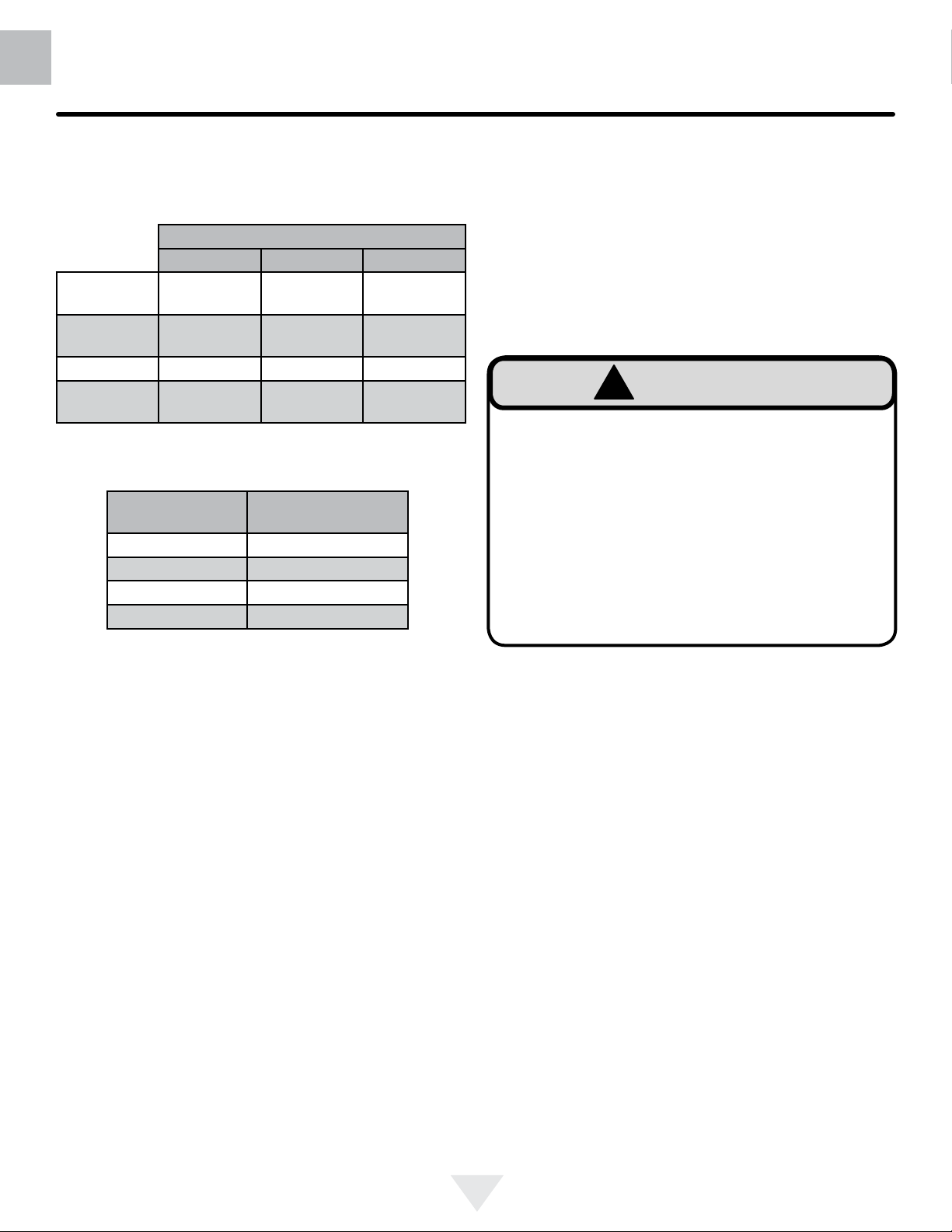
This beer dispensing unit will support
rel. The double draft tower units can support two sixth (1⁄6)
barrels of beer. See chart below for quantity of beer in each
barrel size.
1/6 barrel 1/4 Barrel 1/2 Barrel
5
23
Height
Diameter
Gallons 5.16 7.75 15.5
#12 ounce
Glasses
Keg Size
5 gallon Corny 15 to 22
1/6 barrel 14 to 21
1/4 Barrel 10 to 14
1/2 Barrel 5 to 7
⁄16"
(59.2 cm)
1
9
⁄4"
(23.5 cm)
60 82 163
Table A
USING YOUR BEER DISPENSER
1
⁄2 barrel or 1⁄4 bar-
Barrel Sizes
1413⁄16"
(37.6 cm)
17"
(43.2 cm)
#of kegs per
5 pound CO2 Tank
235⁄16"
(59.2 cm)
17" to 171⁄4"
(43.2 to 43 cm)
Tools required for installation:
Flat bladed screwdriver
Phillips screwdriver
Pliers
Adjustable wrench or a 11⁄8" open end wrench
1⁄2" open end wrench
!
WARNING
CO2 can be dangerous. If it becomes difcult to
breathe and/or your head starts to ache, a high
concentration of carbon dioxide may be present.
Leave the area immediately.
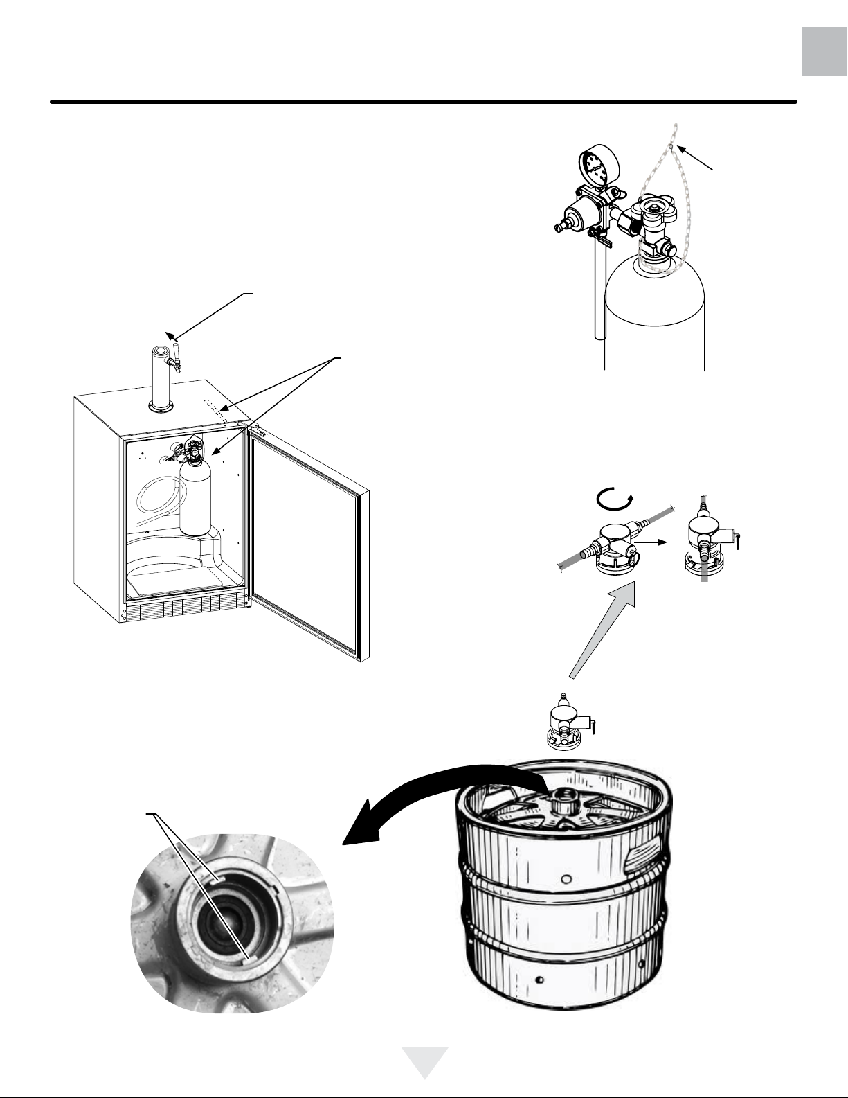
• The CO2 tank must always be connected to the
regulator. Never connect the tank to the keg.
• The CO2 tank must be securely mounted in the
upright position. Secure it with the chain provided.
• Never drop or throw the CO2 tank.
• Keep the CO2 tank away from heat.
• Ventilate the area after a CO2 leak.
Table B
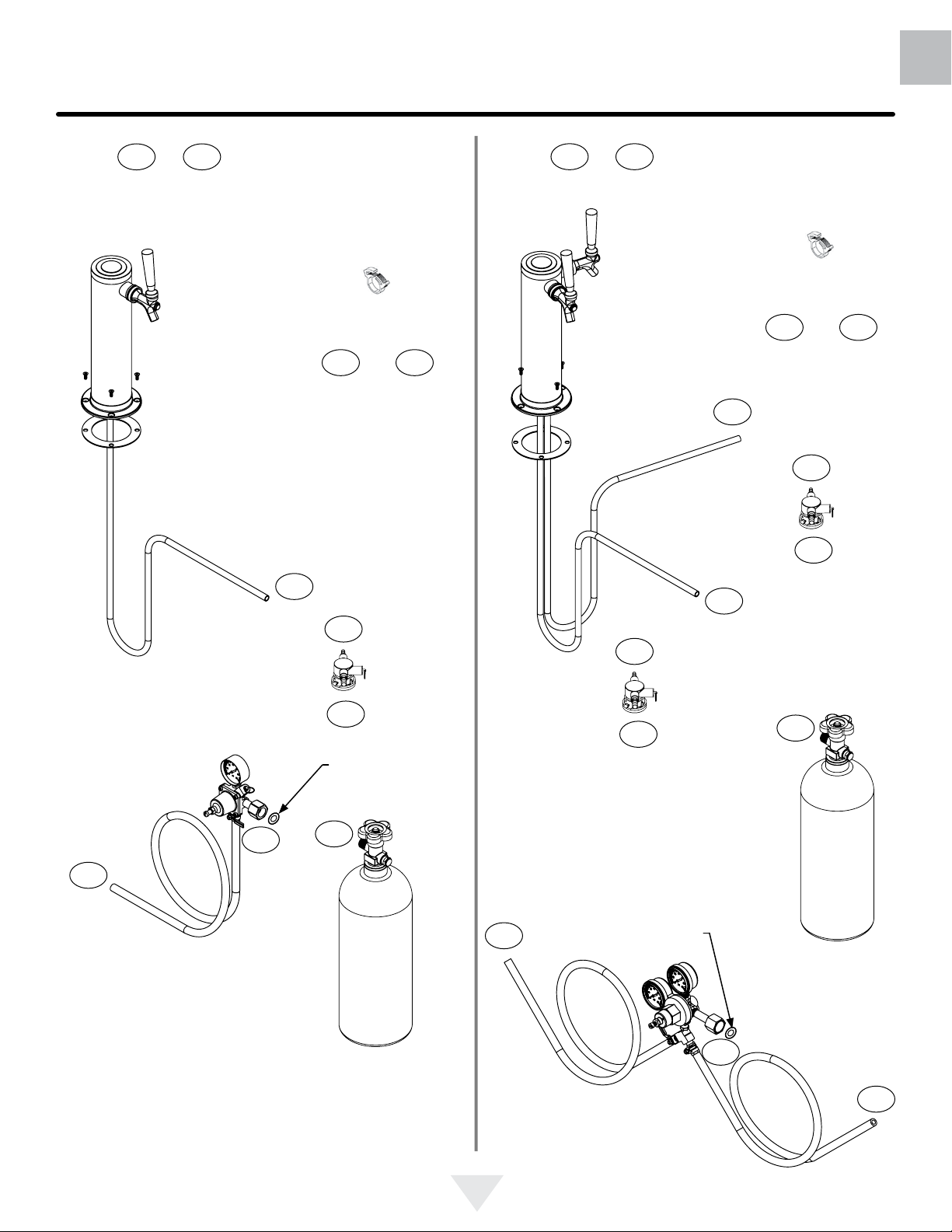
Tap Equipment and Assembly
Your dispensing kit includes the following parts:
Polished stainless steel tower with clear beer line (single
or double dispense)
Tower Gasket
Phillips oval head screws
Knob for Tower (Faucet Handle)
Keg coupler(s)
CO2 regulator with red gas line(s) attached
Empty 5 pound CO2 tank
Plastic clamp(s) large and small
Faucet wrench
1. Remove shelving and packaged components from the
interior of the refrigerator before beginning the assembly process.
2. Take your empty 5 pound CO2 tank to your local gas
supply dealer to be lled. You can usually nd them in
your "yellow pages" under "Welding Supply" or "Fire
Protection". One 5 pound tank can process many kegs
(see table "B") Your dealer should supply you with a
new plastic washer every time the tank is lled. This
washer is used at the regulator to tank connection. See
Figure 15 and 22 on page 11. Replace the old washer
with the new one whenever the tank is relled.
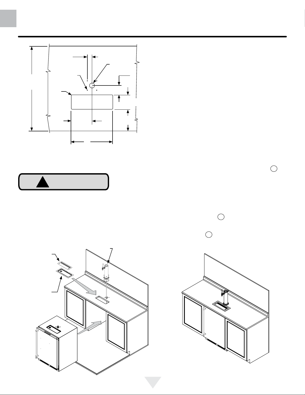
3. Tower mounting (if you are installing the unit under a
counter skip to step 4). If you are mounting the tower
directly to the top of the refrigerator, rst remove the
four screws from the top of the refrigerator. Remove the
foam plug from the large hole in the top of the refrigerator. Feed the clear beer line through the tower gasket
and the large hole in the refrigerator top. Align the 4
holes in the tower with the 4 holes in the refrigerator
top and secure the tower with the 4 screws removed
previously. Skip to step 5.
10
Page 11
USING YOUR BEER DISPENSER
US
CA
Single Dispense Tower Kit
Connect to ,etc........
A A
Single
Dispense
Tower
Figure 12
Figure 13
Hose clamps
use for connections
A
and
A
C
Double Dispense Tower Kit
Connect to ,etc........
A A
Figure 17
Double
Dispense
Tower
Figure 18
Hose clamps
use for connections
A
A
A
C
Figure 19
A
and
C
Keg
Coupler
C
Regulator
Figure 15
with red
airline
B
A
Figure 14
Keg
Coupler
C
New plastic
washer
B
5 Pound
CO2 Tank
Figure 16
C
Regulator
with red
airline
A
C
New plastic
washer
Figure 22
Keg
Coupler
Figure 20
B
B
5 Pound
CO2 Tank
Figure 21
C
11
Page 12
US
CA
USING YOUR BEER DISPENSER
Rear of counter top
3
⁄8"
1
counter
top depth
5
25
⁄16"
(64.3 cm)
Diameter
1
⁄4" (6 mm)
radii,
typical
(3.5 cm)
typical
to suit
(15.6 cm)
1
6
⁄8"
1
12
⁄4"
(31.1 cm)
1
1
⁄2" (38 mm)
Diameter
(16.2 cm)
7
2
⁄38"
(7.3 cm)
41⁄4"
(10.8 cm)
3
6
⁄8"
Figure 23
!
CAUTION
The cutout dimensions shown in Figure 23 are based on
a 255⁄16" (64.3 cm) deep counter top. Your counter top may
be different than this and require other front to back dimensioning. Refer to the product dimensions on page 8 when
determining the required dimensions.
4. If you are installing your keg refrigerator under a
counter you will need to drill 5 holes in the counter top
to mount the tower. The rst hole is a 11⁄2" diameter
hole located at the center of the tower for the beer
line, locate approximately 131⁄2" (34.3 cm) from the
front edge of the counter top (based on a counter top
depth of 255⁄16"). Next drill the 4 tower mounting holes
per the dimensions in Figure 23. The hole diameter
is dependent on the counter top material and if screw
anchors are required. The screws supplied are in the
literature pack and are a #10 x 1" type AB stainless
steel screw. Mark and cut the rectangular cutout for
the drain sump. After the holes are drilled and the
keg refrigerator is in place under the counter top feed
the beer line through the tower gasket, the 11⁄2" hole
in the counter top and the hole in the top of the keg
refrigerator. Mount the tower to the counter top with the
4 screws provided. Place the counter top drain sump,
from the literature pack, in the rectangular hole with the
radius cutout to the rear around the tower and place
the grate in the sump.
5. Mount the regulator to the CO
2 tank (connection
B
)
use the new plastic washer you received from the gas
supply company. Note that the regulator has left hand
threads and has to be turned counterclockwise to
tighten. Tighten with the adjustable wrench or the 11⁄8"
open end wrench.
6. Connect the red air line(s) from the regulator to the
large air line tting on the keg coupler with a large
hose clamp (connection C).
7. Connect the clear beer line from the tower to the small
air line tting on the keg coupler with a small hose
clamp (connection A).
Grate from top of
beer dispenser
Counter top
sump from
literature pack
Tower
Figure 25
Figure 24
12
Page 13
USING YOUR BEER DISPENSER
US
CA
8. Locate the CO
shown in Figure 26 and secure with the chain. Close
the faucet handle on the tower.
9. Hooking up the keg coupler to the keg: Verify the coupler is in the "OFF" position (see Figure 27a).Align the
lugs on the keg with the corresponding openings on the
keg coupler and turn clockwise until the coupler stops
(about 90°). Push down and twist the top of the coupler
clockwise to allow gas to enter the keg.
2 tank in the corner of the refrigerator as
Push faucet handle back toward
tower to close the faucet
Chain-The chain is fastened
and taped to the top of the
interior liner. Remove the tape
and secure the CO
place in the back right corner.
Loop chain around top of tank
and connect with "S" hook.
Connect with
"S" hook
Figure 26a
2 tank in
Rotate the top of the coupler counter clockwise to extend the coupler
to the to the "OFF"position.
Lugs
on keg
Figure 26
Figure 27a
Coupler
extended
Figure 27b
Figure 27
13
Page 14
US
CA
USING YOUR BEER DISPENSER
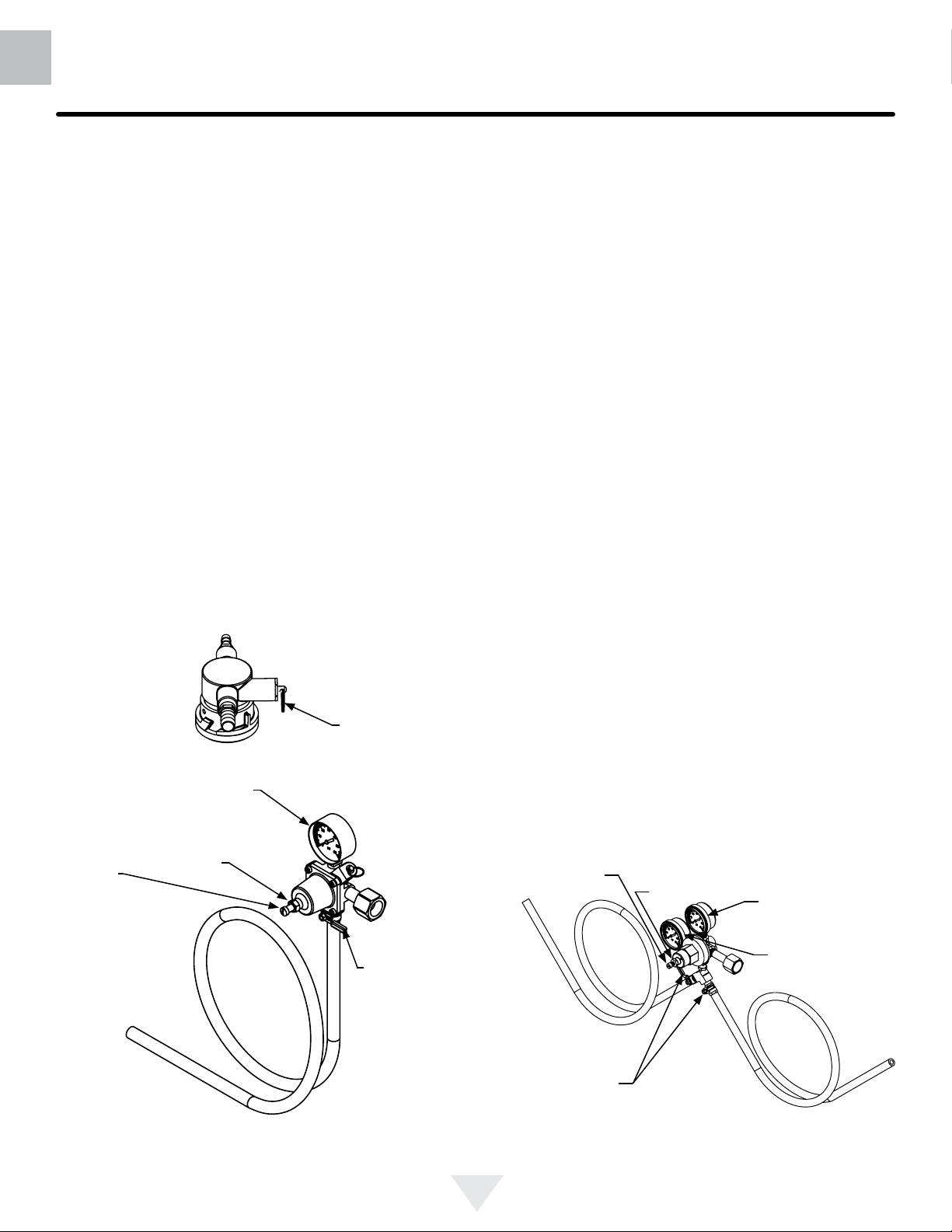
CO2 Regulator (Single Dispense Tower)
Your beer dispenser comes equipped with a 5 pound CO2
tank and a single gauge regulator. The gauge reads the
pressure being supplied to the beer keg. Follow the procedure below to adjust the pressure to 12 - 14 psi (0.8 to
1 bar) for lager beer or 9 - 12 psi (0.6 to 0.8 bar) for ale's.
To adjust the pressure (Single Gauge):
1. Close the shutoff valve at the bottom of the regulator.
2. Be sure the faucet handle is closed on the tower (see
Figure 26).
3. Loosen the lock nut by turning ↶ counterclockwise using the
adjustment of the pressure adjustment screw.
4. With the at bladed screwdriver turn the adjustment
screw ↷ clockwise to increase the pressure or ↶ counterclockwise to decrease the pressure.
5. Open the shutoff valve on the bottom of the regulator. The gauge reading may drop but will return very
quickly.
6. Pull the ring on the keg coupler to allow the gas to ow
momentarily.
7. Make any ne adjustments if necessary with the adjustment screw.
8. Tighten the locknut with the 1⁄2" open end wrench by
turning clockwise ↷.
1
⁄2" open end wrench until loose, this will allow
Ring on keg
Figure 28
coupler
CO2 Regulator (Double Dispense Tower)
Your beer dispenser comes equipped with a 5 pound CO2
tank and a dual gauge regulator. The lower gauge should
be reading approximately 750 psi (52 bar) when the tank is
properly lled and the tank is not in the refrigerator (at room
temperature). The tank will read less when chilled. Use this
lower gauge as an indicator of how much CO2 you have left
in the tank.
The upper gauge reads the pressure being supplied to the
beer keg. Follow the procedure below to adjust the pressure to 12 - 14 psi (0.8 to 1 bar) for lager beer or 9 - 12 psi
(0.6 to 0.8 bar) for ale's.
To adjust the pressure (Upper Gauge):
1. Close the shutoff valves at the bottom of the regulator.
2. Be sure the faucet handle is closed on the tower (see
Figure 29).
3. Loosen the lock nut by turning ↶ counterclockwise using the
adjustment of the pressure adjustment screw.
4. With the at bladed screwdriver turn the adjustment
screw ↷ clockwise to increase the pressure or ↶ counterclockwise to decrease the pressure.
5. Open the shutoff valve on the bottom of the regulator. The gauge reading may drop but will return very
quickly.
6. Pull the ring on the keg coupler to allow the gas to ow
momentarily.
7. Make any ne adjustments if necessary with the adjustment screw.
8. Tighten the locknut with the 1⁄2" open end wrench by
turning clockwise ↷.
1
⁄2" open end wrench until loose, this will allow
Pressure Gauge
Pressure
Adjustment
Screw
Figure 29 (Regulator for
Single Dispense Tower)
Lock Nut
shutoff valve
(closed position shown)
position shown)
14
Pressure
Adjustment
Screw
(2) shutoff
valves (closed
Figure 30 (Regulator for
Double Dispense Tower)
Lock Nut
Upper Gauge
Lower Gauge
Page 15
USING YOUR BEER DISPENSER AND CARE AND CLEANING
US
CA
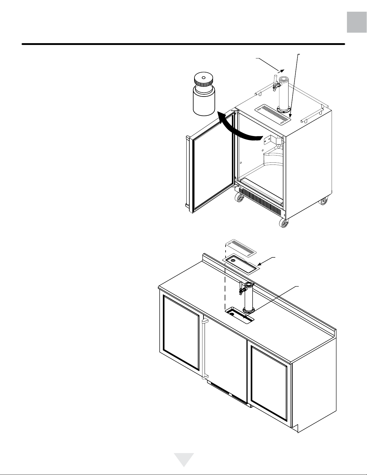
Drain kit (All Models): The drain kit is shipped in
place and ready to use. To empty: Pull drain hose out of
bottle cap, remove bottle from unit, unscrew cap and discard waste and rinse bottle. Reinstall bottle in unit.
Cleaning the drain sump:
On a free standing beer dispenser remove the grate from
in front of the tower, clean with soap and water and dry
before reinstalling. Clean the sump area with soapy water
and dry. (See gure 31).
On a built in beer dispenser remove the grate and counter top sump, clean with soap and water and dry before
reinstalling. Clean the sump area with soapy water and dry.
(See Figure 32).
Push faucet handle back toward
tower to close the faucet
Unscrew
cap
Figure 31
Removable
grate for cleaning sump area
Counter top
sump
Clean and dry
sump area
15
Figure 32
Page 16

US
CA
CARE AND CLEANING
Cleaning and Maintaining Dispensing System
The dispensing system needs to be cleaned between
usage to prevent spoilage and/or foul taste in your beer.
Cleaning
Remove the keg coupler from the keg if necessary. Close the
gas valve(s) below the regulator, remove both the red gas
line(s) and clear beer line(s) from the keg coupler(s) by removing the plastic hose clamps (See Figure 33). Soak and brush
the keg coupler in hot water or a sanitizing solution. Rinse
thoroughly with clean water. Dry all parts and reassemble.
Hose clamps can be
released by a lateral
movement to the head.
Figure 33
Figure 34
After removing the
handle the shaft will
slide out the back of the
faucet
Figure 36
Soak all faucet parts in hot water or a solution of hot water
and a sanitizing solution. Do not use soap. Rinse thoroughly with clean water.
Reassemble faucet, assemble faucet to tower (be sure
faucet is in off position), and turn on gas valve.
Unscrew knurled
cap on faucet body
and remove handle
assembly
Front Grille
Be sure that nothing obstructs the required air ow openings
in front of the cabinet. At least once or twice a year, brush or
vacuum lint and dirt from the front grille area (see page 4).
Faucet Cleaning
Turn off the gas supply with the shutoff valve(s) under the
regulator (see Figure 29 or 30) and open the faucet to relieve the pressure. To remove the faucet from the tower use
the spanner wrench provided. Place the pin on the wrench
into the hole on the faucet collar and turn clockwise ↷ to
remove the faucet. (See Figure 35).
Remove the knurled cap from the faucet body just below
the handle and pull the handle assembly from the faucet.
This will allow the shaft to be removed from the back of the
faucet, see Figure 36.
Place pin on
wrench into hole
in faucet collar.
Figure 35
!
CAUTION
SHOCK HAZARD: Disconnect electrical power from the
appliance before cleaning with soap and water.
Cabinet
The stainless steel cabinet can be washed with either a
mild soap and water and thoroughly rinsed with clear water.
NEVER use abrasive scouring cleaners. Dry thoroughly
with a terry towel.
Interior
Wash interior compartment with mild soap and water. Do
NOT use an abrasive cleaner, solvent, polish cleaner or
undiluted detergent.
Care of Appliance
1. Avoid leaning on the door, you may bend the door
hinges or tip the appliance.
2. Exercise caution when sweeping, vacuuming or mop-
ping near the front of the appliance. Damage to the
grille can occur.
3. Periodically clean the interior of the appliance as needed.
In the Event of a Power Failure
If a power failure occurs, try to correct it as soon as possible. Minimize the number of door openings while the
power is off so as not to adversely affect the appliance's
temperature.
16
Page 17

CARE AND CLEANING
Long term storage / winterization:
1. Time to Winterize, when the daily low ambient temperature is at or below 38°F (3.3°C).
!
CAUTION
Operating of the unit at ambient temperatures below the
recommended Winterization temperature will void your warranty.
2. Turn unit off, (see page 9).
3. Remove all contents.
4. If necessary, move the unit so you can gain access to
the rear of the product.
5. Unplug the unit from the power outlet.
6. It is also recommended that the power to the outlet be
turned-off if the circuit is not required for other items
during the Winter season.
7. Shut-off CO2 tank valve.
8. Drain beer line(s)
Figure 37
US
CA
Front grille
Front grille screw
a. Remove keg coupler (sankey tap), (see
page 16).
b. Remove faucet on tower, (see page 16).
c. Beer lines will gravity drain.
d. Clean beer line tubing.
9. Disassemble faucet and clean, (see page 16).
10. Soak and clean Sankey Low-Boy tap, (see page 16).
11. When cleaning unit pay particular attention to any
cracks and crevices that may have accumulated dirt
and debris.
12. Remove the front toe-grille, (see Figures 37 and 38),
and use a brush and vacuum to clean dirt and debris
from beneath the unit.
13. Thoroughly clean the toe-grille and re-install on the
unit.
14. Remove the rear access cover, (see Figure 39), and
use a brush and vacuum to clean dirt and debris from
the machine compartment.
• If the plastic defrost drain pan located
under the compressor contains water,
use a sponge to remove as much
water as possible
15. Thoroughly clean the rear access cover and re-install
on the unit.
16. Wipe down all interior surfaces with anti-bacterial
cleaner to be followed with clean rinse water to remove
any residual chemicals which could cause staining. Do
not use any abrasive cleaners or scouring pads.
• Remove plastic oor protector and
stainless steel lower edge guard to
clean underneath.
Figure 38a
Clean out
behind
grille
Figure 38
Floor protector
Remove oor
protector and
edge guard
and clean
Spacer
Edge
guard
Grille
17
Page 18

US
CA
Figure 39
CARE AND CLEANING
17. Leave door open and allow to completely dry out before closing door.
18. Thoroughly clean the door gasket with anti-bacterial
cleaner to be followed with clean rinse water to remove
any residual chemicals.
19. Thoroughly clean the exterior with a cleaner approved
for stainless steel . Do not use any abrasive cleaners
or scouring pads.
20. Any mounting hardware / fasteners that are showing
signs of corrosion should be replaced.
21. Once the exterior has been thoroughly cleaned, you
may want to apply a coating of car wax to help protect
Remove 11
screws from
around the
perimeter of the
access cover
with a 5⁄16" nut
driver.
against spotting from moisture, dirt, and debris that
may accumulate on the surfaces during the Winterization period.
After completion of the above, you may choose to store the
unit indoors, although this is not required.
Figure 40
Remove the power
cord from the grommet
in the access cover.
Soak up water
from plastic
drain pan if
necessary
Start-Up After Long-Term Storage:
1. Connect the unit to electrical power.
2. If stored outside, it is recommended that the unit again
be thoroughly inspected per the storage instructions
above to address any dirt or debris from the weather
and/or animals/insects.
3. Turn unit on and conrm your desired control settings.
4. Allow 24-hrs for the unit to stabilize before loading
contents.
Clean out
debris
18
Page 19

STAINLESS STEEL MAINTENANCE
US
CA
Background
Stainless steel does not stain, corrode, or rust as easily as
ordinary steel, but it is not stain or corrosion proof. Stainless steels can discolor or corrode if not maintained properly.
Stainless steels differ from ordinary carbon steels by the
amount of chromium present. It is this chromium that
provides an invisible protective lm on the surface called
chrome-oxide. This protective chrome-oxide lm on the
surface can be damaged or contaminated, which may
result in discoloration, staining, or corrosion of the base
metal.
Care & Cleaning
Routine cleaning of the stainless steel surfaces will serve to
greatly extend the life of your product by removing contaminants. This is especially important in coastal areas which
can expose the stainless to severe contaminants such as
halide salts, (sodium chloride).
It is strongly recommended to periodically inspect and thoroughly clean crevices, weld points, under gaskets, rivets,
bolt heads, and any locations where small amounts of liquid
could collect, become stagnant, and concentrate contaminates. Additionally, any mounting hardware that is showing
signs of corrosion should be replaced.
Note: Stainless steel products should never be installed, or
stored in close proximity to chlorine chemicals.
Whichever cleaning product you chose, it should be used
in strict accordance with the instructions of the cleaner
manufacturer.
Frequency of cleaning will depend upon the installation
location, environmental, and usage conditions.
Choosing a Cleaning Product
The choice of a proper cleaning product is ultimately that
of the consumer, and there are many products from which
to choose. Depending upon the type of cleaning and the
degree of contamination, some products are better than
others.
Typically the most effective and efcient means for routine
cleaning of most stainless steel products is to give the surfaces a brisk rubbing with a soft cloth soaked in warm water
and a gentle detergent, or mild mixture of ammonia. Rubbing should, to the extent possible, follow the polish lines of
the steel, and always insure thorough rinsing after cleaning.
Although some products are called "stainless steel cleaners," some may contain abrasives which could scratch the
surface, (compromising the protective chrome-oxide lm),
and some many contain chlorine bleach which will dull,
tarnish or discolor the surface if not completely removed.
After the stainless surfaces have been thoroughly cleaned,
a good quality car wax may be applied to help maintain the
nish.
19
Page 20

US
CA
ENERGY SAVING TIPS
The following suggestions will minimize the
cost of operating your refrigeration appliance.
1. Do not install your appliance next to a hot appliance
(cooker, dishwasher, etc.), heating air duct, or other
heat sources.
2. Install product out of direct sunlight.
3. Ensure the front grille vents at front of appliance beneath door are not obstructed and kept clean to allow
ventilation for the refrigeration system to expel heat.
4. Plug your appliance into a dedicated power circuit. (Not
shared with other appliances).
5. When initially loading your new product, or whenever
large quantities of warm contents are placed within
refrigerated storage compartment, minimize door
openings for the next 12 hours to allow contents to pull
down to compartment set temperature.
6. Maintaining a relatively full storage compartment will
require less appliance run time than an empty compartment.
7. Ensure door closing is not obstructed by contents
stored in your appliance.
8. Allow hot items to reach room temperature before placing in product.
9. Minimize door openings and duration of door openings.
10. Use the warmest temperature control set temperature
that meets your personal preference and provides the
proper storage for your stored contents.
11. When on vacation or away from home for extended pe-
riods, set the appliance to warmest acceptable tem perature for the stored contents.
12. Set the control to the “off” position if cleaning the
appliance requires the door to be open for an extended
period of time.
20
Page 21

TROUBLESHOOTING AND OBTAINING SERVICE
US
CA
Before You Call for Service
If the appliance appears to be malfunctioning, read through
this manual rst. If the problem persists, check the troubleshooting guide below. Locate the problem in the guide and
refer to the cause and its remedy before calling for service.
The problem may be something very simple that can be
solved without a service call. However, it may be required
to contact your dealer or a qualied service technician.
!
WARNING
Electrocution Hazard
• Never attempt to repair or perform maintenance on
the appliance until the main electrical power has been
disconnected. Turning the appliance control "OFF"
does not remove electrical power from the unit's wiring.
• Replace all parts and panels before operating.
How to Obtain Service:
For warranty service, please contact your local service
provider or DCS Customer Care at (888) 936-7872. Before
you call, please have the following information ready:
• Model Number (the serial plate is located on the upper
left side, inner wall).
• Serial Number (the serial plate is located on the upper left
side, inner wall).
• Code (the serial plate is located on the upper left side,
inner wall).
• Date of installation
• A brief description of the problem
Your satisfaction is of the utmost importance to us. If a
problem cannot be resolved to your satisfaction, please
write or email us at:
Write:
Fisher & Paykel and DCS
Appliances Inc
695 Town Centre Drive, Suite #180 Costa Mesa
CA 92626-1902
USA
Email:
customer.care@sherpaykel.com
Problem Possible Cause Remedy
Appliance not cold enough
(See “Adjusting the temperature" on
page 9)
Appliance too cold
(See “Adjusting the Temperature” on
page 9)
Noise or Vibration • Appliance not level
Appliance will not run. • Appliance turned off
• Control set too warm
• Content temperature not stabilized.
• Excessive usage or prolonged
door openings.
• Airow to front grille blocked.
• Door gasket not sealing properly.
• Control set too cold
• Door gasket not sealing properly.
• Fan hitting tube obstruction.
• Power cord not plugged in.
• No power at outlet.
• Adjust temperature colder. Allow 24 hours for temperature to
stabilize.
• Allow temperature to stabilize for
at least 24 hours.
• Airow must not be obstructed to
front grille. See “clearances” on
page 4.
• Replace door gasket.
• Adjust temperature warmer.
Allow 24 hours for temperature to
stabilize.
• Replace door gasket.
• Level appliance, see “Leveling
Legs” on page 4.
• Contact a qualied service technician.
• Turn appliance on. See “Starting
your appliance” on page 9.
• Plug in power cord.
• Check house circuit.
21
Page 22

US
CA
WARRANTY
Limited Warranty
When you purchase any new DCS Refrigeration Product,
you automatically receive a Two Year Limited Warranty
covering parts and labor for servicing within the 48
mainland United States, Hawaii, Washington, D.C. and
Canada. In Alaska the Limited Warranty is the same
except that you must pay to ship the Product to the service
shop or for the service technician’s travel to your home.
Products for use in Canada must be purchased through
the authorized Canadian distribution channel to ensure
regulatory compliance.
You receive an additional Three Year Limited Warranty
(for a total of Five Years) covering parts for the sealed
refrigeration system (compressor, evaporator, condenser,
lter dryer, and connecting tubing) within the 48 mainland
United States, Hawaii, Washington, D.C. and Canada. In
Alaska the Limited Warranty for the sealed refrigeration
system is the same except that you must pay to ship the
Product to the service shop or the service technician’s
travel to your home.
If the product is installed in a motor vehicle, boat or similar
mobile facility, you receive the same two year warranty, but
you must bring the vehicle, boat or mobile facility containing
the product to the service shop at your expense, or pay the
service technicians to travel to the location of the product.
Fisher & Paykel Undertakes to:
Repair without cost, with limited expectations described
herein, to the owner either for material or labor any part
of the Product, the serial number of which appears on the
Product, which is found to be defective. In Alaska, you
must pay to ship the Product to the service shop or for the
service technician’s travel to your home.
If we are unable to repair a defective part of the Product after a reasonable number of attempts, at our option we may
replace the part or the Product, or we may provide you a
full refund of the purchase price of the Product (not including installation or other charges).
This warranty extends to the original purchaser and any
succeeding owner of the Product during the term of warranty, for products purchased for ordinary single-family
home use.
Limited Warranty
How Long Does this Limited Warranty Last?
Our liability under this Limited Warranty expires Two
Years from the date of purchase of the Product by the
rst consumer.
Our liability for repair of defects in any sealed refrigeration
system (compressor, evaporator, condenser, lter dryer,
and connecting tubing) extends an additional Three Years,
for a total of Five Years from the date of purchase of the
Product by the rst consumer.
Our liability under any implied warranties, including the
implied warranty of merchantability (an unwritten warranty
that the Product is t for ordinary use) also expires Two
Years (or such longer period as required by applicable law)
from the date of purchase of the Product by the rst consumer. Some states do not allow limitations on how long
an implied warranty lasts, so this limit on implied warranties
may not apply to you.
Fisher & Paykel will honor any warranty required by the
law of the particular country or state in which the product
is sold.
This Warranty Does Not Cover
A.
Service calls that are not related to any defect
in the Product. The cost of a service call will
be charged if the problem is not found to be a
defect of the Product. For example:
1. Correct faulty installation of the Product.
2. Instruct you how to use the Product.
3. Replace house fuses, reset circuit breakers, correct
house wiring or plumbing, or replace light bulbs.
4. Correct fault(s) caused by the user.
5. Change the set-up of the Product.
6. Unauthorized modications of the Product.
7. Noise and vibration that is considered normal e.g.
drain sounds, regeneration noises and user warning
beeps.
8. Correcting damage caused by pests e.g. rats, cockroaches etc.
9. Used in commercial applications.
All service under this Limited Warranty shall be provided
by Fisher & Paykel Appliances Inc. or its Authorized DCS
Service Agent during normal business hours.
There is no warranty for commercial purchase or use.
Defects caused by factors other than:
B.
1. Normal domestic use or
2. Use in accordance with the Product’s Use and Care
Guide.
22
Page 23

C.
Defects to the Product caused by accident,
neglect, misuses, re, ood or Act of God.
D.
The cost of repairs carried out by non-authorized repairers or the cost of correcting such
unauthorized repairs.
E.
Travel Fees and associated charges incurred
when the product is installed in a location
with limited or restricted access.(i.e. airplane
ights, ferry charges, isolated geographic
areas).
F.
Normal recommended maintenance as set
forth in the Product’s Use and Care Guide.
If you have an installation problem contact
your dealer or installer. You are responsible
for providing adequate electrical, exhausting
and other connection facilities.
This product has been designed for use in a
normal domestic (residential) environment.
This product is not designed for commercial
use (whatsoever). Any commercial use by a
customer will terminate/affect this products
limited warranty.
We are not responsible for consequential or
incidental damages (including without limitation the cost of repairing or replacing other
property damaged if the Product is defective
or any of your expenses caused if the Product
is defective). Some states do not allow the
exclusion or limitation of incidental or consequential damages, so the above limitation or
exclusion may not apply to you.
WARRANTY
Commercial use
This warranty applies to appliances used in residential applications; it does not cover their use in commercial situations.
No other warranties
This Limited Warranty is the complete and exclusive agreement between you and Fisher & Paykel Appliances Inc.
regarding any defect in the Product and no other express
warranty has been made or will be made on behalf of
Fisher & Paykel. None of our employees (or our Authorized
Service Agents) are authorized to make any addition or
modication to this Limited Warranty.
Warrantor: Fisher & Paykel Appliances, Inc.
If you need further help concerning this Limited Warranty,
or to make a claim under this warranty, please call us at the
above number, or write to:
Fisher & Paykel and DCS
Appliances Inc
695 Town Centre Drive, Suite #180 Costa Mesa
CA 92626-1902
USA
This Limited Warranty gives you specic legal rights, and
you may also have other rights which vary from country to
country and from state to state.
Fisher & Paykel Appliances Inc. is a leading manufacturer
of premium quality cooking and specialty appliances under
the Fisher & Paykel and DCS brands.
US
CA
How to get service
Please read this Use and Care Guide. If you then have any
questions about operating the Product, need the name of
your local DCS Authorized Service Agent, or believe the
Product is defective and wish service under this Limited
Warranty, please contact your dealer or call us at:
TOLL FREE 1-888-936-7872 or contact us through our web
site: www.dcsappliances.com
You may be required to provide reasonable proof of the
date of purchase of the Product before the Product will be
serviced under this Limited Warranty.
23
Page 24

US
CA
(FR)
TABLE DES MATIÈRES
Table des matières :
Informations de sécurité ........................................................24
Déballage de votre appareil ...................................................25
Enregistrement de la garantie ................................................25
Installation de votre appareil ..................................................26
Dégagement requis pour l’appareil ...................................26
Mise à niveau de l’appareil ................................................26
Raccordement électrique ..................................................27
Installation du dispositif antibasculement ..............................28
Dimensions du produit ............................................................30
Utilisation de votre commande électronique...........................31
Démarrage de votre appareil .............................................31
Mise en « MARCHE » ou « ARRÊT » de votre appareil ....31
Réglage de la température .................................................31
Fonctionnement du distributeur de bière ............................31
Alarmes ..............................................................................31
Porte entrouverte ...........................................................31
Défaillance du capteur de température ..........................31
Alarme de température élevée ou basse .......................31
Mise en sourdine de l’alarme .............................................31
Utilisation de votre distributeur de bière .................................32
Équipement de robinet et assemblage ...............................32
Régulateur de CO2 ............................................................36
Ensemble d’évacuation ......................................................37
Entretien et nettoyage ...........................................................37
Nettoyage du drain d’évacuation ........................................37
Nettoyage du coupleur de fût à bière .................................38
Nettoyage du robinet .........................................................38
Grille frontale .....................................................................38
Bâti .....................................................................................38
Intérieur ..............................................................................38
Rangement de longue durée / hivernage ..............................39
Entretien de l’acier inoxydable .............................................41
Conseils d’économie d’énergie ..............................................42
Dépannage ............................................................................43
Obtention de service ..............................................................43
Garantie .................................................................................44
Consignes de sécurité importantes
Les consignes de sécurité et avertissements contenus
dans ce guide ne couvrent pas de façon exhaustive toutes
les conditions et situations possibles. Soyez prudents et
agissez avec précaution et attention lors de l’installation,
l’entretien ou l’utilisation de cet appareil.
Portez attention aux symboles,
indications et étiquettes de sécurité.
!
MISE EN GARDE
AVERTISSEMENT – Vous risquez de subir des
blessures graves, voire mortelles, si vous ne respectez
pas ces instructions.
!
ATTENTION
MISE EN GARDE – Risques ou manipulations dange-
reuses susceptibles d’entraîner des blessures et des dommages matériels / au produit.
REMARQUE
REMARQUE – Informations importantes visant à assurer
une installation et une utilisation sans problème.
État de la Californie – Avertissements de la Proposition 65 :
AVERTISSEMENT : Cet appareil contient un ou plusieurs
produits chimiques reconnus par l’État de la Californie comme
étant cancérigènes.
AVERTISSEMENT : Cet appareil contient un ou plusieurs
produits chimiques reconnus par l’État de la Californie
comme étant sources d’anomalies congénitales ou nuisibles
à la reproduction.
24
Page 25

DÉBALLAGE DE VOTRE APPAREIL
!
MISE EN GARDE
RISQUE DE POIDS EXCESSIF
Assurez-vous d’être au moins deux personnes
pour déplacer le produit. Le non-respect de cette
consigne peut entraîner des blessures.
Retirez l’emballage intérieur
Votre appareil a été emballé en veillant à ce que toutes
les pièces risquant d’être endommagées lors du transport
soient xées solidement. Retirez tous les matériaux d’emballage intérieurs et tous les rubans adhésifs qui maintiennent les
composants internes en place. Le manuel du propriétaire est
inclus à l’intérieur du produit, dans un sac de plastique avec la
carte d’enregistrement de garantie et les autres accessoires.
Important
Conservez la boîte et les matériaux d’emballage jusqu’à ce
que vous terminiez l’inspection minutieuse de votre appareil
pour vous assurer qu’il est en bon état. En cas de dommage,
l’emballage sera requis comme preuve d’endommagement
causé lors du transport. Veuillez ensuite mettre au rebut de
manière responsable tous les éléments d’emballage.
US
CA
(FR)
Un message à l’intention de nos clients
Nous vous remercions d’avoir choisi ce réfrigérateur d’extérieur DCS. Nous avons élaboré ce Guide d’installation,
d’utilisation et d’entretien dans le but d’expliquer les fonctions
uniques de cet appareil. Ce guide contient des informations
très utiles sur la façon adéquate d’installer, de faire fonctionner et d’effectuer l’entretien de votre nouvel appareil
an de pouvoir en proter en toute sécurité pendant de
nombreuses années.
Si vous avez des questions au sujet de ce produit, communiquez avec un représentant du service à la clientèle DCS
par téléphone :
1-888-936-7872, ou par courriel :
customer.care@sherpaykel.com
REMARQUE : Veuillez noter le numéro de modèle, le code
et le numéro de série sur cette page pour référence ultérieure
(la plaque signalétique se trouve sur la paroi interne, dans
la partie supérieure gauche).
NUMÉRO DE MODÈLE :
CODE :
NUMÉRO DE SÉRIE :
!
MISE EN GARDE
AVERTISSEMENT – Jetez les sacs de plastique
qui peuvent représenter un risque de suffocation.
Remarque à l’intention du client
Cette marchandise a été soigneusement emballée et
inspectée avant de quitter notre usine. Le détaillant assume
la responsabilité de la livraison au moment de l’acceptation
de la marchandise. Toute réclamation pour perte ou dommage
encouru lors du transport doit être présentée au détaillant.
REMARQUE
NE RENVOYEZ AUCUNE MARCHANDISE ENDOMMAGÉE AU FABRICANT – DÉPOSEZ VOTRE RÉCLAMATION
AUPRÈS DU DÉTAILLANT.
!
ATTENTION
REMARQUE : Inspectez le produit pour vous assurer
qu’aucun dommage n’a été causé lors de l’expédition. En cas
de dommage, communiquez avec l’expéditeur pour effectuer
une demande d’indemnisation. DCS par Fisher & Paykel n’est
pas responsable des dommages causés lors de l’expédition.
NE METTEZ PAS au rebut les matériaux d’emballage
(boîte, palette, sangles) avant d’avoir terminé l’inspection
de l’appareil.
!
MISE EN GARDE
AVERTISSEMENT – Aidez à prévenir
les accidents
Les risques d’emprisonnement et de suffocation
des enfants sont des problèmes toujours présents.
Les réfrigérateurs mis au rebut ou abandonnés sont
toujours dangereux, même s’ils sont laissés sans
surveillance pendant quelques heures seulement.
Si vous devez mettre au rebut votre ancien réfrigérateur,
veuillez suivre les instructions ci-dessous pour éviter
les accidents.
Si l’appareil a été expédié, déplacé ou entreposé dans une
position autre que verticale pendant une durée quelconque,
laissez l’appareil en position verticale pendant au moins
24 heures avant de le brancher. Cela permettra à l’huile
de retourner au compresseur. Le fait de brancher l’appareil
immédiatement pourrait endommager les pièces internes.
Avant de mettre au rebut votre ancien réfrigérateur
ou congélateur :
• Retirez les portes ou les tiroirs.
• Laissez les tablettes en place an d’éviter que
les enfants puissent facilement pénétrer à l’intérieur.
25
Page 26

US
CA
(FR)
INSTALLATION DE VOTRE APPAREIL
Sélection de l’emplacement
Un emplacement adéquat permet d’assurer le fonctionnement
optimal de votre appareil. Nous recommandons un emplacement éloigné des sources de chaleur, où l’appareil ne sera pas
exposé à un ensoleillement direct. Pour assurer le fonction-
nement de votre produit selon les spécications, la plage de
température recommandée à l’emplacement d’installation est
de 55 à 115 °F (13 à 46 °C).
Dégagement requis pour l’appareil
La partie avant inférieure de l’appareil nécessite une ventilation adéquate. Gardez cette zone ouverte et libre de toute
obstruction. Les armoires adjacentes et le comptoir peuvent
être installés autour de l’appareil, à condition que la grille frontale ne soit pas obstruée.
Pattes de
nivellement
avant
Figure 1
Grille frontale –
gardez cette
zone dégagée.
Pattes de
nivellement
arrière
!
ATTENTION
Grille frontale
N’obstruez pas la grille frontale. Les ouvertures de la grille
frontale permettent à l’air de circuler dans l’échangeur de
chaleur du condensateur. Toute obstruction de cette circulation d’air entraînerait une utilisation d’énergie accrue et une
perte de puissance du système de refroidissement. Pour cette
raison, il est important que cette zone ne soit pas obstruée
et que les ouvertures de la grille demeurent propres (voir
Figure 1). L’utilisation d’une grille fabriquée sur mesure n’est
pas recommandée, car cela pourrait limiter la circulation d’air.
Pattes de nivellement
Les pattes de nivellement dans les coins avant et arrière de
l’appareil doivent être réglées de manière à ce que l’appareil repose fermement au sol, en étant au niveau de droite à
gauche et d’avant en arrière. La hauteur hors tout de votre
appareil peut être ajustée entre la hauteur minimum, 333⁄4 po
(85,7 cm), en vissant la patte de nivellement (sens horaire ↷),
et la hauteur maximum, 343⁄4 po (88,3 cm) en dévissant
la patte de nivellement (sens antihoraire ↶).
Pour régler les pattes de nivellement, placez l’appareil sur une
surface solide et protégez le plancher pour éviter de causer
des égratignures sous les pattes. Avec l’aide d’une autre
personne, inclinez l’appareil vers l’arrière pour accéder aux
pattes de nivellement avant. Élevez ou abaissez les pattes à
la hauteur requise en les tournant. Répétez cette procédure à
l’arrière en inclinant l’appareil vers l’avant, en faisant preuve
de prudence. Sur une surface de niveau, vériez si l’appareil
est bien de niveau et ajustez-le si nécessaire.
Il est possible de desserrer les vis de la grille frontale an
d’ajuster cette dernière à la hauteur souhaitée. Une fois
l’ajustement terminé, serrez les deux vis de la grille frontale. (Voir Figure 2).
26
Grille frontale
Vis de grille frontale
Figure 2
Page 27

INSTALLATION DE VOTRE APPAREIL
US
CA
(FR)
Figure 3
Ne retirez pas
la broche de
mise à la terre
Figure 4
!
MISE EN GARDE
Risque de choc électrique
• N’utilisez aucune rallonge avec cet appareil. Cela
peut s’avérer dangereux et risque de compromettre
le fonctionnement du produit.
• Cet appareil ne doit en aucun cas être raccordé à une
alimentation électrique qui n’est pas mise à la terre.
• Ne retirez pas la broche de mise à la terre du cordon
d’alimentation. (Voir Figure 3).
• N’utilisez aucun adaptateur. (Voir Figure 4).
• N’éclaboussez ou n’arrosez pas l’appareil avec
un boyau. Cela pourrait causer un choc électrique
risquant d’entraîner des blessures graves ou mortelles.
Raccordement électrique
Un circuit dédié de 115 volts, 15 ampères avec mise à la terre
est requis.
Ce produit est équipé en usine d’un cordon d’alimenta-
tion muni d’une che à trois broches avec mise à la terre.
Cette che doit être branchée dans une prise avec mise
à la terre de type correspondant et conforme au Code
national de l’électricité, ainsi qu’aux codes et règlements
locaux en vigueur (voir Figure 5). Si le circuit ne comporte
pas de prise avec mise à la terre, le client a la responsabilité et l’obligation de faire installer une prise d’alimentation
adéquate. La broche de mise à la terre ne doit en aucun
cas être coupée ou retirée.
Figure 5
REMARQUE
Les disjoncteurs différentiels de fuite à la terre (DDFT)
sont sujets aux déclenchements indésirables entraînant
une mise en arrêt de l’appareil. Les DDFT ne sont généralement pas utilisés sur les circuits avec des équipements
devant fonctionner sans surveillance pendant de longues
périodes, à moins que cela ne soit nécessaire pour assurer la conformité aux codes de construction et règlements
locaux.
27
Page 28

US
CA
(FR)
INSTALLATION DU DISPOSITIF ANTIBASCULEMENT
POUR LES INSTALLATIONS NON ENCASTRÉES
!
MISE EN GARDE
• TOUS LES APPAREILS
PEUVENT BASCULER ET AINSI
CAUSER DES BLESSURES.
• INSTALLEZ LA PIÈCE DE
FIXATION ANTIBASCULEMENT
FOUNIE AVEC L’APPAREIL.
• SUIVEZ LES INSTRUCTIONS
CI-DESSOUS.
Pièce de xation
antibasculement
211⁄2 po
(54,6 cm)
Patte de nivellement
Vue de dessous
du distributeur
de bière
Devant de
l’appareil
Dispositif antibasculement
!
MISE EN GARDE
Si votre réfrigérateur n’est pas installé sous un comptoir
(non encastré), vous devez utiliser un dispositif antibasculement installé conformément à ces instructions. Si
le réfrigérateur est déplacé de son emplacement pour
une raison quelconque, assurez-vous que le dispositif
s’emboîte correctement avec la pièce de xation antibasculement lorsque vous réinstallez le réfrigérateur à
son emplacement initial. Si le dispositif n’est pas correctement emboîté, le réfrigérateur risque de basculer et
d’entraîner des dommages matériels ou des blessures.
REMARQUE
Lors de l’installation sur un plancher en béton, des xations
pour béton sont requises (non comprises avec l’ensemble
antibasculement).
Figure 6
Instructions étape par étape pour localiser
la position de la pièce de xation :
1) Choisissez l’endroit où vous souhaitez placer le distributeur
de bière. Glissez-le en place, en veillant à ne pas endommager le plancher et en laissant un dégagement de 1 po
(2,5 cm) à partir du mur arrière an de laisser de l’espace pour
la pièce de xation antibasculement.
2) Élevez les pattes de nivellement arrière d’environ
(6 mm) an de permettre l’emboîtement avec la pièce de xation antibasculement. Mettez l’appareil de niveau en réglant
toutes les pattes de nivellement, au besoin. Tournez la patte
de nivellement dans le sens des aiguilles d’une montre pour
abaisser l’appareil, ou dans le sens inverse pour l’élever.
3) Assurez-vous de placer le distributeur de bière à l’endroit
souhaité, puis marquez sur le plancher le coin correspondant aux parties arrière et latérale de l’appareil, à l’endroit où
la pièce de xation antibasculement sera installée. Si l’installation ne permet pas de marquer le coin arrière de l’appareil,
tracez des lignes temporaires sur le plancher pour marquer le
coin avant de l’appareil, en excluant la porte. Glissez le distributeur de bière hors de son emplacement. À partir de la ligne
temporaire, prolongez la ligne de paroi latérale de 211⁄2 po
(54,6 cm) vers l’arrière, comme illustré dans la
1
⁄4 po
Figure 6.
!
ATTENTION
Les revêtements de sol doivent être protégés à l’aide de matériaux appropriés pour éviter les dommages lors du déplacement de l’appareil.
Installation avec xation au plancher
La pièce de xation antibasculement doit être située sur
le plancher, dans le coin arrière gauche ou droit du distributeur
de bière, comme illustré dans la
Figure 6.
4) Alignez la pièce de xation antibasculement sur les marques
tracées sur le plancher, de manière à ce que le côté de la pièce
de xation soit aligné avec le côté de la marque de l’appareil et
que les encoches en « V » sur la pièce de xation antibascu-
lement soient alignées avec l’extrémité de la ligne de 211⁄2 po
(54,6 cm) (ligne correspondant à l’arrière de l’appareil).
5) Fixez la pièce de xation antibasculement au plancher en
utilisant la vis fournie. (Voir
6) Replacez l’appareil sur son emplacement, en vous assurant
que la patte de nivellement arrière glisse sous la pièce de
xation antibasculement qui s’emboîte dans la fente.
Figure 7).
28
Page 29

INSTALLATION DU DISPOSITIF ANTIBASCULEMENT
POUR LES INSTALLATIONS NON ENCASTRÉES
REMARQUE
Lorsque la pièce de xation antibasculement montée
au plancher est utilisée, la hauteur d’ajustement minimum
de l’appareil augmente de 3⁄8 po (9 mm).
US
CA
(FR)
Ligne du devant de l’appareil
211⁄2 po
(54,6 cm)
Figure 7
Ligne du côté de l’appareil
Ligne de l’arrière de l’appareil
Patte de
nivellement
arrière
Vis
Encoches en « V »
dans la pièce de xation
Figure 7a
Encoches
en « V »
dans la pièce
de xation
29
Page 30

US
CA
(FR)
DIMENSIONS DU PRODUIT
DIMENSIONS DE L’OUVERTURE DIMENSIONS DE L’APPAREIL
MODÈLE « A » « B » « C » « D » « E » « F » « G » « H » « J »
24 ¼ po (61,6 cm)
Tous
les modèles
24 ½ po (62 cm)
(avec ensemble de
garnitures latérales
DCS en option)
**34 po à 35 po
(86,4 à 88,9 cm)
*
237⁄8 po
(60,7 cm)
333⁄4 po à 343⁄4 po
(85,7 à 88,3 cm)
2323⁄32 po
(60,2 cm)
261⁄4 po
(66,7 cm)
4613⁄32 po
(117,9 cm)
261⁄4 po
(66,7 cm)
MODÈLE
Tous
les modèles
« C »
DONNÉES DU PRODUIT
ALIMENTATION
REQUISE***
115 V/60 Hz/15 A
« A »
« B »
POIDS DU
PRODUIT
140 lb
(63,6 kg)
« E »
1115⁄16 po
(30,3 cm)
121⁄4 po
(31,1 cm)
« D »
« J »
« E »
Figure 9
« H »
11 po
(27,9 cm)
211⁄2 po
(54,6 cm)
« F »
« G »
« D »
Figure 8
Figure 8a
S’il est nécessaire de gagner de l’espace à l’intérieur de
l’ouverture, vous pouvez découper un trou dans l’armoire
adjacente an d’y passer le cordon d’alimentation pour
l’acheminer à une prise de courant. Une autre façon
d’augmenter la profondeur d’ouverture disponible est
d’encastrer la prise de courant dans le mur arrière an
de récupérer l’épaisseur de la che du cordon d’alimen-
tation.
* La profondeur de l’ouverture peut varier selon chaque installation. Pour encastrer la totalité de la porte, la dimension « F »
avec 1 po (2,5 cm) supplémentaire est requise pour l’épais-
seur de la che du cordon d’alimentation.
** L’ouverture minimale requise doit être supérieure à
la hauteur ajustée de l’appareil.
*** Un circuit dédié de 15 ampères avec mise à la terre est
requis. Respectez tous les codes locaux du bâtiment lors
de l’installation du raccordement électrique et de l’appareil.
30
Page 31

UTILISATION DE VOTRE COMMANDE ÉLECTRONIQUE
Alarm
F
Figure 10
Gros plan de
la commande
Set
Press and Hold Press and Hold
Démarrage de votre distributeur de bière
Branchez le cordon d’alimentation du distributeur de bière dans
une prise de courant. Votre distributeur de bière commencera à
refroidir après sa mise sous tension.
Si votre distributeur de bière ne démarre pas, vériez s’il est mis en
marche et si la température réglée est sufsamment froide.
Colder Warmer
ON/OFF
US
CA
(FR)
Mise en MARCHE ou ARRÊT de votre distributeur de bière
Lorsque le distributeur de bière est en marche, sa tempéra-
ture est indiquée sur l’afcheur. Pour éteindre le distributeur de
bière, maintenez la touche « ON/OFF » (« MARCHE/ARRÊT »)
enfoncée pendant trois secondes. « OFF » (« ARRÊT ») appa-
raîtra sur l’afcheur.
Lorsque le distributeur de bière n’est pas en marche, « OFF »
apparaît sur l’afcheur. Pour mettre en marche le distributeur de
bière, maintenez la touche « ON/OFF » enfoncée pendant trois
secondes. La température du distributeur de bière sera indiquée
sur l’afcheur.
Réglage de la température
Pour régler la température du distributeur de bière, maintenez
la touche « SET » (« RÉGLAGE ») enfoncée. Lorsque vous
appuyez sur la touche « SET », l’afcheur indique la température
réglée. Tout en maintenant la touche « SET » enfoncée, appuyez
sur la touche « WARMER » (« PLUS CHAUD ») ou « COLDER »
(« PLUS FROID ») pour régler la température.
Fonctionnement du distributeur de bière
La plage de température disponible du distributeur de bière est
de 34 à 46 °F (1 à 8 °C).
Votre distributeur de bière peut prendre jusqu’à 24 heures pour
atteindre la température souhaitée. Cette durée dépend de la
quantité de contenu et de la fréquence d’ouvertures et de fermetures de la porte.
Pour de meilleurs résultats, laissez le distributeur de bière
atteindre la température réglée avant d’insérer le contenu.
Une fois le contenu en place, laissez la température se stabiliser
pendant au moins 48 heures avant d’apporter des modications
à la température réglée.
Alarmes
La fonction d’afchage numérique permet le suivi du fonctionnement de votre distributeur de bière et vous avise à l’aide d’une
série d’alarmes sonores et visuelles.
Le panneau d’afchage clignotera en indiquant « do » et le
voyant DEL situé dans le coin supérieur gauche de l’afcheur
s’allumera sous « Alarm » (« Alarme »). L’alarme s’arrête dès que
la porte est refermée.
• Alarme de porte entrouverte : Si la porte est
laissée ouverte pendant plus de cinq minutes,
l’alarme retentit à des intervalles d’une seconde.
Figure 11
• Défaillance du capteur de température : Si
le contrôleur détecte que le capteur de température
ne fonctionne pas correctement, une alarme de
capteur de température retentira à des intervalles d’une (1)
seconde. « E1 » clignotera sur le panneau d’afchage et le voyant
DEL situé dans le coin supérieur gauche de l’afcheur s’allumera
sous « Alarm ».
• Alarme de température élevée ou basse : Si
votre appareil atteint une température inacceptable
par rapport à votre réglage, l’alarme retentira à des
intervalles d’une (1) seconde. Le panneau d’afchage clignotera en indiquant « Hi » (« Élevée »)
ou « Lo » (« Basse »), selon le problème, et le
voyant DEL situé dans le coin supérieur gauche de l’afcheur
s’allumera sous « Alarm » (« Alarme »). Cette alarme signale une
variation de température du compartiment de 10 degrés ou plus
par rapport à votre réglage, pendant plus de 1 heure. L’alarme
retentira jusqu’à ce que le problème soit corrigé.
REMARQUE
Lors du démarrage initial de l’appareil, l’alarme de température
élevée pourrait retentir jusqu’à ce que la température intérieure
atteigne votre température réglée. L’alarme de température élevée
peut également s’activer lors de l’ouverture de la porte pendant
une période prolongée (par exemple, nettoyage ou alarme de
porte entrouverte), d’une utilisation fréquente ou du chargement
de produits tièdes. Après le déclenchement d’une alarme de tempé-
rature élevée, vériez tous les aliments périssables pour vous
assurer qu’ils sont toujours propres à la consommation.
Mise en sourdine de l’alarme
Appuyez sur n’importe quelle touche pour mettre en sourdine
l’alarme sonore.
REMARQUE
Cette action met en sourdine l’alarme uniquement. Si la cause
ayant déclenché l’alarme est toujours présente, le code d’alarme
continuera de clignoter avec émission d’un rappel sonore de
20 secondes toutes les 60 minutes.
31
Page 32

US
CA
(FR)
UTILISATION DE VOTRE DISTRIBUTEUR DE BIÈRE
Ce distributeur de bière peut fonctionner avec un baril de
format 1⁄2 ou 1⁄4. La colonne de tirage double peut fonctionner
avec deux barils de bière de format 1⁄6. Consultez le tableau
ci-dessous pour connaître la quantité de bière contenue dans
chaque format de baril.
Formats de baril
Baril 1/6 Baril 1/4 Baril 1/2
Hauteur
Diamètre
⁄16 po
23
(59,2 cm)
1
9
⁄4 po
(23,5 cm)
1413⁄16 po
(37,6 cm)
17 po
(43,2 cm)
235⁄16 po
(59,2 cm)
17 po à
171⁄4 po
(43,2 à 43 cm)
5
Gallons 5,16 7,75 15,5
Nombre de
verres de
60 82 163
12 onces
Tableau A
Nombre de fûts par
Format de fût
Réservoir de
5 livres de CO2
« Corny » 5 gallons 15 à 22
Baril 1/6 14 à 21
Baril 1/4 10 à 14
Baril 1/2 5 à 7
Outils requis pour l’installation :
Tournevis à tête plate
Tournevis à tête étoilée
Pinces
Clé à molette ou clé plate de 1
Clé plate de 1⁄2 po
!
MISE EN GARDE
Le CO2 peut être dangereux. En cas de difculté
à respirer et/ou de maux de tête, il peut y avoir
une concentration élevée de dioxyde de carbone.
Quittez immédiatement la pièce.
• Le réservoir de CO2 doit toujours être raccordé au
régulateur. Ne jamais raccorder le réservoir au fût.
• Le réservoir de CO2 doit être xé solidement en
position verticale. Utiliser la chaîne fournie pour
le xer.
• Ne jamais faire tomber ou projeter le réservoir
de CO2.
• Conserver le réservoir de CO2 à l’écart de
la chaleur.
• Aérer la pièce après une fuite de CO2.
1
⁄8 po
Tableau B
Équipement de robinet et assemblage
Votre ensemble de distributeur comprend les pièces
suivantes :
Colonne en acier inoxydable poli avec conduite de bière
transparente (distributeur simple ou double)
Joint de colonne
Vis à tête ovale étoilée
Bouton pour colonne (poignée de robinet)
Coupleur(s) de fût
Régulateur de CO2 avec conduite(s) de gaz
rouge(s) xée(s)
Réservoir vide de 5 livres de CO2
Collier(s) de serrage en plastique, grand et petit
Clé à robinet (clé anglaise)
1. Retirez les tablettes et les composants emballés de l’intérieur du réfrigérateur avant de commencer l’assemblage.
2. Apportez votre réservoir vide de 5 livres de CO2 à un fournisseur de gaz local pour le faire remplir. Vous pouvez
normalement trouver un fournisseur dans les pages
jaunes, sous la section « Fourniture de soudage » ou
« Protection contre les incendies ». La capacité d’un
réservoir de 5 livres est sufsante pour plusieurs fûts
(consultez le tableau « B »). Votre détaillant doit vous
fournir une nouvelle rondelle de plastique à chaque
remplissage du réservoir. Cette rondelle est utilisée au
niveau du raccordement du régulateur avec le réservoir.
Consultez les Figures 15 et 22 à la page 33. Remplacez
l’ancienne rondelle par la nouvelle à chaque remplissage
du réservoir.
3. Montage de colonne (si vous installez l’appareil sous
un comptoir, passez à l’étape 4). Si vous montez
la colonne directement sur le dessus du réfrigérateur,
retirez d’abord les quatre vis situées sur le dessus du
réfrigérateur. Retirez le bouchon en mousse de la grande
ouverture située dans le haut du réfrigérateur. Faites
passer la conduite de bière transparente dans le joint de
la colonne et la grande ouverture sur le dessus du réfrigérateur. Alignez les 4 trous de la colonne avec les 4 trous
sur le dessus du réfrigérateur, puis xez la colonne
à l’aide des 4 vis retirées précédemment. Passez
à l’étape 5.
32
Page 33

UTILISATION DE VOTRE DISTRIBUTEUR DE BIÈRE
US
CA
(FR)
Ensemble de colonne de distribution simple
Raccordez à , etc........
A A
Colonne de
distribution
simple
Figure 12
Figure 13
Colliers de serrage
à utiliser pour
raccordements
A
C
et
A
Ensemble de colonne de distribution double
Raccordez à , etc........
A A
Figure 17
Colonne de
distribution
double
Figure 18
Colliers de serrage
à utiliser pour raccor-
dements
A
C
et
A
A
Coupleur
de fût
C
Figure 19
A
C
Régulateur
avec conduite
d’air rouge
Figure 15
B
A
Figure 14
Coupleur
de fût
C
Nouvelle rondelle
de plastique
B
Réservoir de 5 livres
de CO2
Figure 16
C
Régulateur
avec conduite
d’air rouge
A
Coupleur
de fût
Figure 20
C
Nouvelle rondelle
de plastique
B
Figure 22
B
Réservoir de
5 livres de CO2
Figure 21
C
33
Page 34

US
CA
(FR)
UTILISATION DE VOTRE DISTRIBUTEUR DE BIÈRE
Arrière du comptoir
3
⁄8 po
Profondeur
du comptoir
5
25
⁄16 po
(64,3 cm)
Diamètre
adapté
1
⁄4 po (6 mm)
de rayon,
type
1
(3,5 cm)
type
1
6
⁄8 po
(15,6 cm)
(31,1 cm)
12
1
⁄4 po
1
1
⁄2 po
(38 mm)
de diamètre
7
⁄38 po
2
(7,3 cm)
41⁄4 po
(10,8 cm)
3
⁄8 po
6
(16,2 cm)
Figure 23
!
ATTENTION
Les dimensions illustrées dans la Figure 23 sont basées
sur une profondeur de comptoir de 255⁄16 po (64,3 cm).
Votre comptoir pourrait être différent et nécessiter des
dimensions différentes. Consultez les dimensions du
produit à la page 30 au moment de déterminer les dimensions requises.
Grille au-dessus
du distributeur
Colonne
de bière
1. Si vous installez votre réfrigérateur à fût sous un comptoir,
vous devrez percer 5 trous dans le comptoir pour monter
la colonne. Le premier trou de 1
1
⁄2 po de diamètre est
situé au centre de la colonne pour la conduite de bière;
percez-le à environ 13
1
⁄2 po (34,3 cm) du rebord avant
du comptoir (en se basant sur une profondeur de comptoir de 25
5
⁄16 po). Percez ensuite les 4 trous de montage
de la colonne, conformément aux dimensions indiquées
dans la Figure 23. Le diamètre du trou varie selon
le matériel du comptoir et la nécessité d’utiliser des pièces
d’ancrage à vis. Les vis fournies dans l’ensemble de
documentation sont en acier inoxydable AB de type
n° 10 x 1 po. Marquez et découpez l’ouverture rectangulaire pour le drain d’évacuation. Une fois les trous percés
et le réfrigérateur à fût placé sous le comptoir, faites
passer la conduite de bière dans le joint de la colonne,
le trou de 1
1
⁄2 po dans le comptoir et le trou sur le dessus
du réfrigérateur à fût. Montez la colonne sur le comptoir
à l’aide des 4 vis fournies. Placez le drain d’évacuation
du comptoir, fourni avec l’ensemble de documentation,
dans l’ouverture rectangulaire avec la découpe en rayon
à l’arrière, près de la colonne. Placez ensuite la grille dans
le drain.
2. Montez le régulateur sur le réservoir de CO2 (raccorde-
B
ment
) en utilisant la nouvelle rondelle de plastique
fournie par le fournisseur de gaz. Comme le régulateur
est muni de letage à gauche, vous devez le tourner dans
le sens inverse des aiguilles d’une montre pour le serrer.
Serrez-le avec une clé à molette ou clé plate de 11⁄8 po.
3. Connectez la ou les conduite(s) d’air rouge(s) provenant
du régulateur au grand raccord de conduite d’air sur le
coupleur de fût avec un grand collier de serrage (raccordement
C
).
4. Connectez la conduite de bière transparente provenant
de la colonne au petit raccord de conduite d’air sur le
coupleur de fût avec un petit collier de serrage (raccorde-
A
ment
).
Drain de comptoir
fourni avec
l’ensemble de
documentation
Figure 25
Figure 24
34
Page 35

UTILISATION DE VOTRE DISTRIBUTEUR DE BIÈRE
5. Placez le réservoir de CO2 dans le coin du réfrigérateur,
comme illustré dans la Figure 26, puis utilisez la chaîne pour
le xer. Fermez la poignée de robinet sur la colonne.
6. Branchement du coupleur de fût sur le fût : Vériez que
le coupleur est à la position « OFF » (« ARRÊT ») (voir
Figure 27a). Alignez les butées sur le fût avec les butées
correspondantes sur le coupleur de fût, puis tournez dans
le sens des aiguilles d’une montre jusqu’à ce que le coupleur
s’arrête (environ 90°). Poussez vers le bas et faites pivoter
la partie supérieure du coupleur dans le sens des aiguilles
d’une montre an de permettre au gaz de pénétrer dans le fût.
Poussez la poignée de robinet vers
l’arrière, en direction de la colonne,
pour fermer le robinet
Chaîne – La chaîne est xée à la partie
supérieure du panneau intérieur. Retirez le ruban adhésif et xez le réservoir de CO
Enroulez la chaîne autour de la partie
supérieure du réservoir et utilisez le
crochet en « S » pour la raccorder.
2 dans le coin arrière droit.
US
CA
(FR)
Raccordez
à l’aide du
crochet en
« S »
Figure 26a
Tournez la partie supérieure du
coupleur dans le sens inverse
des aiguilles d’une montre
an de placer le coupleur à
la position « OFF ».
Butées
sur le fût
Figure 26
Figure 27a
Coupleur
prolongé
Figure 27b
Figure 27
35
Page 36

US
CA
(FR)
UTILISATION DE VOTRE DISTRIBUTEUR DE BIÈRE
Régulateur de CO2 (colonne de distribution
simple)
Votre distributeur de bière est fourni avec un réservoir de
5 livres de CO
mesure la pression acheminée au fût de bière. Suivez la
procédure ci-dessous pour régler la pression de 12 à 14 psi
(0,8 à 1 bar) pour la bière lager ou de 9 à 12 psi (0,6 à 0,8 bar)
pour la bière ale.
2 et un régulateur à jauge simple. La jauge
Pour régler la pression (jauge simple) :
1. Fermez la valve d’arrêt située dans le bas du régulateur.
2. Assurez-vous que la poignée de robinet est fermée sur
la colonne (voir
3. Desserrez le contre-écrou en le tournant ↶ dans le sens
inverse des aiguilles d’une montre à l’aide de la clé plate
de 1⁄2 po jusqu’à ce qu’il soit desserré; cela vous permettra
de régler la vis d’ajustement de pression.
4. Utilisez le tournevis à tête plate pour tourner la vis d’ajustement ↷ dans le sens des aiguilles d’une montre an
d’augmenter la pression ou ↶ dans le sens inverse des
aiguilles d’une montre an de réduire la pression.
5. Ouvrez la valve d’arrêt située dans le bas du régulateur.
La mesure de la jauge pourrait baisser, mais elle retournera très rapidement à la valeur de pression.
6. Tirez sur l’anneau du coupleur de fût an de permettre au
gaz de circuler momentanément.
7. Eectuez des ajustements plus précis, si nécessaire, à
l’aide de la vis d’ajustement.
8. Serrez le contre-écrou à l’aide de la clé plate de 1⁄2 po en
le tournant dans le sens des aiguilles d’une montre ↷.
Figure 26).
Anneau sur
coupleur de fût
Figure 28
Régulateur de CO2 (colonne de distribution
double)
Votre distributeur de bière est fourni avec un réservoir de
5 livres de CO
inférieure doit indiquer une pression d’environ 750 psi (52 bar)
lorsque le réservoir est correctement rempli et à l’extérieur
du réfrigérateur (à la température ambiante). La lecture de
la jauge diminue lorsque le réservoir est réfrigéré. Utilisez
cette jauge inférieure pour déterminer la quantité restante
2 dans le réservoir.
de CO
La jauge supérieure mesure la pression acheminée au fût de
bière. Suivez la procédure ci-dessous pour régler la pression
de 12 à 14 psi (0,8 à 1 bar) pour la bière lager ou de 9 à 12 psi
(0,6 à 0,8 bar) pour la bière ale.
2 et un régulateur à jauge double. La jauge
Pour régler la pression (jauge supérieure) :
1. Fermez les valves d’arrêt situées dans le bas du régulateur.
2. Assurez-vous que la poignée de robinet est fermée sur
la colonne (voir
3. Desserrez le contre-écrou en le tournant ↶ dans le sens
inverse des aiguilles d’une montre à l’aide de la clé plate
1
⁄2 po jusqu’à ce qu’il soit desserré; cela vous permettra
de
de régler la vis d’ajustement de pression.
4. Utilisez le tournevis à tête plate pour tourner la vis d’ajustement ↷ dans le sens des aiguilles d’une montre an
d’augmenter la pression ou ↶ dans le sens inverse des
aiguilles d’une montre an de réduire la pression.
5. Ouvrez la valve d’arrêt située dans le bas du régulateur.
La mesure de la jauge pourrait baisser, mais elle retournera très rapidement à la valeur de pression.
6. Tirez sur l’anneau du coupleur de fût an de permettre
au gaz de circuler momentanément.
7. Eectuez des ajustements plus précis, si nécessaire,
à l’aide de la vis d’ajustement.
8. Serrez le contre-écrou à l’aide de la clé plate de 1⁄2 po en
le tournant dans le sens des aiguilles d’une montre ↷.
Figure 29).
Jauge de pression
Contre-écrou
Vis
d’ajustement
de pression
Valve d’arrêt
(position fermée
illustrée)
Figure 29 (Régulateur pour colonne de distribution simple)
Vis
d’ajustement
de pression
Contre-écrou
Jauge supérieure
Jauge inférieure
(2) Valves d’arrêt
(position fermée
illustrée)
Figure 30 (Régulateur pour
colonne de distribution double)
36
Page 37

UTILISATION DE VOTRE DISTRIBUTEUR DE BIÈRE – ENTRETIEN ET NETTOYAGE
US
CA
(FR)
Ensemble d’évacuation (tous les modèles) :
L’ensemble d’évacuation est installé avant l’expédition
et prêt à l’utilisation. Pour le vider : Tirez le tuyau d’évacuation hors du bouchon, retirez la bouteille de l’appareil,
dévissez le bouchon, puis jetez le contenu et rincez la
bouteille. Réinstallez la bouteille dans l’appareil.
Nettoyage du drain d’évacuation :
Sur un distributeur de bière non encastré, retirez la grille
située devant la colonne, nettoyez-la avec de l’eau et du
savon, puis séchez-la avant de la réinstaller. Nettoyez la zone
du drain avec de l’eau savonneuse, puis séchez-la. (Voir
Figure 31).
Sur un distributeur de bière encastré, retirez la grille et le
drain de comptoir, nettoyez-les avec de l’eau et du savon, puis
séchez-les avant de les réinstaller. Nettoyez la zone du drain
avec de l’eau savonneuse, puis séchez-la. (Voir
Figure 32).
Poussez la poignée de robinet vers
l’arrière, en direction de la
colonne, pour fermer le robinet
Dévissez
le bouchon
Figure 31
Grille amovible
pour le nettoyage
de la zone du
drain
Drain de
comptoir
Nettoyez et
séchez la
zone de drain
37
Figure 32
Page 38

US
CA
(FR)
ENTRETIEN ET NETTOYAGE
Nettoyage et entretien – Système de distributeur
Le système de distributeur doit être nettoyé entre
les utilisations pour éviter une détérioration de votre bière et/
ou un goût désagréable.
Nettoyage
Retirez le coupleur de fût de votre fût, si nécessaire. Fermez
la ou les valve(s) de gaz sous le régulateur, retirez la ou
les conduite(s) de gaz rouge(s) et la ou les conduite(s) de
bière transparente(s) du ou des coupleur(s) de fût en retirant
les colliers de serrage en plastique (voir
tremper et brossez le coupleur de fût dans de l’eau chaude ou
une solution désinfectante. Rincez bien avec de l’eau propre.
Séchez toutes les pièces et réinstallez-les.
Les colliers de serrage
peuvent être relâchés par
un mouvement latéral au
niveau de la tête.
Figure 33
Figure 33). Faites
Figure 34
Une fois la poignée
retirée, le manche
glisse hors du
robinet,
à l’arrière
de celui-ci
Figure 36
Faites tremper toutes les pièces du robinet dans de l’eau
chaude ou une solution d’eau chaude et de produit désinfectant. N’utilisez pas de savon. Rincez bien avec de l’eau
propre.
Réassemblez le robinet, assemblez le robinet sur la colonne
(veillez à ce que le robinet soit en position fermée), puis
ouvrez la valve de gaz.
Dévissez le capuchon
moleté sur le corps de
robinet, puis retirez
l’assemblage de poignée
Grille frontale
Assurez-vous que rien n’obstrue les ouvertures de circulation
d’air requises à l’avant de l’appareil. Au moins une ou deux fois
par année, utilisez une brosse ou un aspirateur pour nettoyer
les débris et la saleté de la zone de grille frontale (voir page 26).
Nettoyage du robinet
Fermez l’alimentation en gaz avec la ou les valve(s) d’arrêt
sous le régulateur (voir
pour évacuer la pression. Pour retirer le robinet de la colonne,
utilisez la clé à griffes fournie. Placez la tige de la clé dans
l’ouverture sur le collet du robinet, puis tournez dans le
sens des aiguilles d’une montre ↷ pour retirer le robinet.
(Voir
Figure 35).
Retirez le capuchon moleté du corps de robinet, juste sous
la poignée, puis tirez sur l’assemblage de la poignée pour
le dégager du robinet. Cela permettra de retirer le manche
de la partie arrière du robinet (voir
Placez la tige
de la clé dans
l’ouverture sur le
collet du robinet.
Figure 29 ou 30) et ouvrez le robinet
Figure 36).
Figure 35
!
ATTENTION
RISQUE D’ÉLECTROCUTION : Déconnectez l’appareil de
l’alimentation électrique avant de le nettoyer avec de l’eau et
du savon.
Bâti
Le bâti en acier inoxydable peut être lavé avec de l’eau et un
savon doux, puis bien rincé avec de l’eau propre. N’utilisez
JAMAIS de nettoyants à récurer abrasifs. Séchez-le bien avec
une serviette éponge.
Intérieur
Lavez le compartiment intérieur avec de l’eau et un savon
doux. N’utilisez PAS de nettoyant abrasif, de solvant, de
nettoyant à poli ou de détergent non dilué.
Entretien de l’appareil
1. Évitez de vous appuyer contre la porte, car cela pourrait
déformer les charnières ou faire basculer l’appareil.
2. Agissez avec prudence lorsque vous balayez, nettoyez à
l’aspirateur ou passez la serpillière à proximité du devant
de l’appareil. Vous pourriez endommager la grille.
3. Nettoyez périodiquement l’intérieur de l’appareil, au besoin.
En cas de panne de courant
Lorsqu’une panne de courant survient, essayez de résoudre
le problème dès que possible. Évitez d’ouvrir la porte inutilement pendant la panne pour ne pas affecter la température
de l’appareil.
38
Page 39

ENTRETIEN ET NETTOYAGE
Rangement de longue durée / hivernage :
1. Moment de préparer l’appareil pour l’hiver : lorsque la
température ambiante minimale quotidienne est égale ou
inférieure à 38 °F (3,3 °C).
!
ATTENTION
Le fonctionnement de l’appareil à des températures ambiantes
sous la température d’hivernage recommandée entraînera
l’annulation de votre garantie.
2. Éteignez l’appareil (voir page 31).
3. Retirez tout le contenu.
4. Si nécessaire, déplacez l’appareil an de pouvoir accéder
à l’arrière du produit.
5. Débranchez l’appareil de la prise de courant.
6. Il est également recommandé de désactiver l’alimentation à la prise de courant si le circuit n’est pas utilisé par
d’autres appareils pendant l’hiver.
7. Fermez la valve du réservoir de CO
8. Égouttez la ou les conduite(s) de bière.
2
.
Figure 37
US
CA
(FR)
Grille frontale
Vis de grille frontale
a. Retirez le coupleur de fût (robinet Sankey) (voir
page 38).
b. Retirez le robinet de la colonne (voir page 38).
c. Les conduites de bière se videront par gravité.
d. Nettoyez la conduite de bière.
9. Démontez le robinet et nettoyez-le (voir page 38).
10. Faites tremper et nettoyez le robinet Low-Boy Sankey
(voir page 38).
11. Lors du nettoyage de l’appareil, accordez une attention
particulière à toute craquelure ou crevasse qui pourrait
avoir accumulé de la saleté et des débris.
12. Retirez la grille inférieure à l’avant (voir
puis utilisez une brosse et un aspirateur pour nettoyer la
saleté et les débris sous l’appareil.
13. Nettoyez bien la grille inférieure et réinstallez-la sur
l’appareil.
14. Retirez le couvercle d’accès arrière (voir
utilisez une brosse et un aspirateur pour nettoyer la saleté
et les débris du compartiment de l’appareil.
• Si le plateau de dégivrage en plastique situé sous
le compresseur contient de l’eau, utilisez une
éponge pour enlever autant d’eau que possible.
15. Nettoyez bien le couvercle d’accès arrière et réinstallez-le
sur l’appareil.
16. Essuyez toutes les surfaces intérieures avec un nettoyant
antibactérien, puis rincez avec de l’eau propre pour
éliminer les résidus chimiques risquant de causer des
taches. N’utilisez pas de nettoyants abrasifs ou de
tampons à récurer.
Figures 37 et 38),
Figure 39), puis
Figure 38a
Retirez le protecteur de plancher
et la protection
de bordure, puis
nettoyez
Nettoyez
derrière
la grille
Protecteur de plancher
Protection
de bordure
• Retirez le protecteur de plancher en plastique
et la protection de bordure inférieure en acier
inoxydable pour nettoyer en dessous.
39
Figure 38
Espaceur
Grille
Page 40

US
CA
(FR)
Figure 39
ENTRETIEN ET NETTOYAGE
17. Laissez la porte ouverte et attendez que le séchage soit
complètement terminé avant de fermer la porte.
18. Nettoyez bien le joint d’étanchéité de la porte avec
un nettoyant antibactérien, puis rincez avec de l’eau
propre pour éliminer les résidus chimiques.
19. Nettoyez bien l’extérieur en utilisant un nettoyant
approuvé pour l’acier inoxydable. N’utilisez pas de
nettoyants abrasifs ou de tampons à récurer.
20. Les pièces de montage / xation présentant des signes
de corrosion doivent être remplacées.
21. Une fois l’extérieur bien nettoyé, vous pouvez appliquer une couche de cire à voiture pour aider à protéger
Retirez les
11 vis autour
du périmètre
du couvercle
d’accès en
utilisant un
tournevis à écrou
de 5⁄16 po.
l’appareil des taches causées par l’humidité, la saleté
et les débris risquant de s’accumuler sur les surfaces
pendant la période d’hivernage.
Après les étapes ci-dessus, vous pouvez choisir de ranger
l’appareil à l’intérieur, mais cela n’est pas requis.
Figure 40
Retirez le cordon
d’alimentation
de l’œillet dans
le couvercle d’accès.
Épongez l’eau
du plateau de
dégivrage en
plastique, si
nécessaire
Démarrage après un rangement de longue
durée :
1. Connectez l’appareil à l’alimentation électrique.
2. S’il est rangé à l’extérieur, nous vous recommandons
d’inspecter soigneusement l’appareil conformément
aux instructions de rangement ci-dessus pour nettoyer
la saleté ou les débris résultant des intempéries et/ou
des animaux/insectes.
3. Mettez l’appareil en marche et conrmez vos réglages
de commande souhaités.
4. Laissez l’appareil se stabiliser pendant 24 heures avant
d’insérer le contenu.
Nettoyez
les débris
40
Page 41

ENTRETIEN DE L’ACIER INOXYDABLE
US
CA
(FR)
Informations générales
L’acier inoxydable ne tache, corrode ou rouille pas aussi
facilement que l’acier standard, mais il n’est pas à l’épreuve
des taches ou de la corrosion. Les aciers inoxydables
peuvent se décolorer ou corroder s’ils ne sont pas entretenus
correctement.
Les aciers inoxydables sont différents des aciers au carbone
standard en raison de leur teneur en chrome. En effet, l’ajout
de chrome leur procure une protection invisible en surface,
nommée oxyde de chrome. Cette pellicule protectrice d’oxyde
de chrome en surface peut être endommagée ou contaminée,
risquant ainsi de causer une décoloration, des taches ou de
la corrosion sur le métal de base.
Entretien et nettoyage
Un nettoyage régulier des surfaces en acier inoxydable contribuera à prolonger considérablement la durée de vie de votre
produit en éliminant les contaminants. Cela est particulièrement important dans les régions côtières où l’acier inoxydable
peut être exposé à des contaminants puissants, tels que
les sels d’halogénures (chlorure de sodium).
Il est vivement recommandé d’inspecter périodiquement et de
bien nettoyer les crevasses, les points de soudure, le dessous
des joints, les rivets, les têtes de boulon et tout emplacement
où de petites quantités de liquide pourraient s’accumuler,
devenir stagnantes et contenir des contaminants. De plus,
les pièces de montage présentant des signes de corrosion
doivent être remplacées.
Une fois les surfaces en acier inoxydable complètement
nettoyées, vous pouvez appliquer de la cire à voiture de bonne
qualité pour aider à préserver le ni.
Remarque : Les appareils en acier inoxydable ne doivent
jamais être installés ou entreposés à proximité de produits
chimiques chlorés.
Quel que soit le produit de nettoyage de votre choix, utilisez-le
conformément aux instructions du fabricant.
La fréquence du nettoyage varie selon l’emplacement d’installation, les conditions environnementales et les conditions
d’utilisation.
Choix d’un produit de nettoyage
La sélection d’un produit de nettoyage convenable est à
la discrétion du client, qui peut choisir parmi de nombreux
produits. Selon le type de nettoyage et le degré de contamina-
tion, certains produits sont plus efcaces que d’autres.
Normalement, le moyen le plus efcace d’effectuer
le nettoyage usuel de la plupart des produits en acier inoxydable consiste à les frotter vigoureusement à l’aide d’un
chiffon doux imbibé d’eau tiède et d’un détergent doux, ou
encore d’un mélange à faible teneur en ammoniaque. Les frottements doivent être dans le sens des lignes de poli de l’acier,
dans la mesure du possible. Ce nettoyage doit toujours être
suivi d’un rinçage complet.
Bien que certains produits soient identiés « nettoyants pour
acier inoxydable », ces derniers pourraient contenir des substances abrasives risquant d’égratigner la surface (en endommageant ainsi la pellicule protectrice d’oxyde de chrome) et
plusieurs d’entre eux contiennent du javellisant au chlore, qui
pourrait ternir ou décolorer la surface s’il n’est pas complètement nettoyé.
41
Page 42

US
CA
(FR)
CONSEILS D’ÉCONOMIE D’ÉNERGIE
Les suggestions suivantes vous aideront à
réduire le coût de fonctionnement de votre
appareil de réfrigération.
1. N’installez pas votre appareil à proximité d’un appareil
générant de la chaleur (cuisinière, lave-vaisselle, etc.), de
conduits de chauffage ou de toute autre source de chaleur.
2. Installez le produit à l’abri de l’ensoleillement direct.
3. Assurez-vous que les ouvertures de la grille frontale
située à l’avant de l’appareil, sous la porte, sont dégagées
et maintenues propres an de permettre au système de
réfrigération d’expulser la chaleur.
4. Branchez votre appareil à un circuit d’alimentation dédié
(non partagé avec d’autres appareils).
5. Lors du chargement initial de votre nouveau produit ou
lorsque vous placez de grandes quantités de contenus
tièdes dans le compartiment de rangement réfrigéré,
évitez d’ouvrir la porte inutilement au cours des 12 pro-
chaines heures an de permettre au contenu d’atteindre la
température réglée pour le compartiment.
6. Un compartiment de rangement relativement plein nécessite une durée de fonctionnement moins importante qu’un
compartiment vide.
7. Lors de la fermeture, assurez-vous que la porte n’est pas
obstruée par des contenus rangés dans votre appareil.
8. Laissez les articles chauds atteindre la température
ambiante avant de les ranger dans l’appareil.
9. Évitez d’ouvrir la porte inutilement et réduisez les durées
d’ouverture de la porte.
10. Utilisez le réglage de température le plus élevé qui correspond à vos préférences personnelles et permet d’obtenir
une température convenable pour les contenus rangés.
11. Lors des vacances ou des périodes d’absence prolongées, réglez l’appareil à la température la plus élevée
acceptable pour les contenus rangés.
12. Réglez la commande à la position « OFF » si le nettoyage
de l’appareil nécessite que la porte soit ouverte pendant
une période prolongée.
42
Page 43

DÉPANNAGE ET OBTENTION DE SERVICE
US
CA
(FR)
Avant d’effectuer un appel de service
Si l’appareil semble fonctionner incorrectement, lisez d’abord
ce manuel dans sa totalité. Si le problème persiste, consultez
le guide de dépannage ci-dessous. Trouvez le problème dans
le guide, puis reportez-vous à la cause et la solution avant
d’effectuer un appel de service. Le problème est parfois très
simple à résoudre, sans qu’un appel de service ne soit nécessaire. Toutefois, il pourrait être nécessaire de communiquer
avec votre détaillant ou un technicien d’entretien qualié.
!
MISE EN GARDE
Risque d’électrocution
• Ne tentez jamais de réparer ou d’effectuer l’entretien de l’appareil avant d’avoir déconnecté l’alimentation électrique. Le fait de régler la commande
de l’appareil à « OFF » n’interrompt pas l’alimentation électrique du câblage de l’appareil.
• Réinstallez toutes les pièces et tous les
panneaux avant de faire fonctionner l’appareil.
Comment obtenir du service :
Pour une réparation sous garantie, veuillez communiquer avec
votre fournisseur de service local ou le service à la clientèle
DCS au (888) 936-7872. Avant d’appeler, veuillez préparer
les informations suivantes :
• Numéro de modèle (la plaque signalétique se trouve sur
la paroi interne, dans la partie supérieure gauche).
• Numéro de série (la plaque signalétique se trouve sur
la paroi interne, dans la partie supérieure gauche).
• Code (la plaque signalétique se trouve sur la paroi interne,
dans la partie supérieure gauche).
• Date de l’installation
• Brève description du problème
Votre satisfaction est importante pour nous. Si un problème
n’est pas réglé à votre satisfaction, veuillez nous écrire ou
nous envoyer un courriel à :
Nous écrire :
Fisher & Paykel and DCS
Appliances Inc
695 Town Centre Drive, Suite #180 Costa Mesa
CA 92626-1902
USA
Nous envoyer un courriel :
customer.care@sherpaykel.com
Problème Cause possible Solution
L’appareil n’est pas sufsamment froid
(Voir « Réglage de la température » à la page 31)
L’appareil est trop froid
(Voir « Réglage de la température » à la page 31)
Bruit ou vibration • L’appareil n’est pas de niveau.
L’appareil ne fonctionne pas. • L’appareil est éteint.
• La commande est réglée à une température trop élevée.
• La température du contenu n’est pas
stabilisée.
• Utilisation excessive ou ouvertures prolongées de la porte.
• Circulation d’air obstruée à la grille
frontale.
• Le joint de porte n’est pas sufsamment
étanche.
• La commande est réglée à une température trop froide.
• Le joint de porte n’est pas sufsamment
étanche.
• Tube causant de l’obstruction
au ventilateur.
• Le cordon d’alimentation n’est pas branché.
• Aucune alimentation à la prise.
• Réglez la commande à une température
plus froide. Attendez 24 heures pour permettre à la température de se stabiliser.
• Laissez la température se stabiliser pendant au moins 24 heures.
• La circulation d’air ne doit pas être obstruée à la grille frontale. Voir « Dégagements » à la page 26.
• Remplacez le joint de porte.
• Réglez la commande à une température
plus élevée.
Attendez 24 heures pour permettre à
la température de se stabiliser.
• Remplacez le joint de porte.
• Mettez l’appareil de niveau (voir
« Pattes de nivellement » à la page 26).
• Contactez un technicien d’entretien
qualié.
• Mettez l’appareil en marche. Voir
« Démarrage de votre appareil » à la
page 31.
• Branchez le cordon d’alimentation.
• Vériez les disjoncteurs de la maison.
43
Page 44

US
CA
(FR)
GARANTIE
Garantie limitée
Lorsque vous achetez un nouveau produit de réfrigération
DCS, vous bénéciez automatiquement d’une garantie limitée
de deux ans s’appliquant aux pièces et à la main-d’œuvre
pour le service dans les 48 États continentaux des ÉtatsUnis, à Hawaï, à Washington DC et au Canada. Les clients
de l’Alaska bénécient de la même garantie limitée, mais ils
doivent payer les frais nécessaires pour la livraison du produit
à l’atelier de réparation ou le déplacement d’un technicien à
leur domicile. Les produits pour l’utilisation au Canada doivent
être achetés auprès du réseau de distribution canadien autorisé pour assurer la conformité aux réglementations.
Vous bénéciez d’une garantie limitée supplémentaire de
trois ans (pour un total de cinq ans) couvrant les pièces du
système de réfrigération scellé (compresseur, évaporateur,
condenseur, déshydrateur-ltre et tube de raccordement) dans
les 48 États continentaux des États-Unis, à Hawaï, à Wash-
ington DC et au Canada. Les clients de l’Alaska bénécient
de la même garantie limitée pour le système de réfrigération scellé, mais ils doivent payer les frais nécessaires pour
la livraison du produit à l’atelier de réparation ou le déplacement d’un technicien à leur domicile.
Si le produit est installé dans un véhicule à moteur, un bateau
ou une installation mobile similaire, vous bénéciez de la
même garantie de deux ans, mais vous devez apporter à vos
frais le véhicule, le bateau ou l’installation mobile contenant le
produit à l’atelier de réparation ou payer le déplacement des
techniciens d’entretien à l’endroit où se trouve le produit.
Fisher & Paykel s’engage à :
Réparer sans frais encouru par le propriétaire, avec certaines
exceptions décrites aux présentes, pour le matériel ou la maind’œuvre pour toute pièce s’avérant défectueuse du Produit
dont le numéro de série gure sur celui-ci. Les clients de
l’Alaska doivent payer les frais nécessaires pour la livraison du
produit à l’atelier de réparation ou le déplacement d’un technicien à leur domicile.
Si nous ne parvenons pas à réparer une pièce défectueuse
du produit après un nombre de tentatives raisonnable, nous
pourrons à notre discrétion remplacer la pièce ou le produit,
ou vous offrir un remboursement complet du prix d’achat du
produit (excluant les frais d’installation ou autres coûts).
Cette garantie est valable pour le propriétaire initial et tout
propriétaire subséquent du Produit pendant la durée de la
garantie, s’il est acheté pour une utilisation normale dans un
domicile familial simple.
Garantie limitée
Quelle est la durée de cette garantie limitée?
Notre responsabilité en vertu de cette garantie limitée expire
deux ans à partir de la date d’achat du produit par le premier
acheteur.
Notre responsabilité pour les réparations de défectuosités
affectant le système de réfrigération scellé (compresseur,
évaporateur, condensateur, déshydrateur-ltre et tube de
raccordement) est prolongée de trois années supplémentaires,
pour un total de cinq années à partir de la date d’achat du
produit par le premier acheteur.
Notre responsabilité en vertu de toute garantie implicite,
incluant la garantie implicite de qualité marchande (la garantie
non écrite que le produit est adéquat pour une utilisation
normale) est également limitée à deux ans (ou une période
plus longue, si cela est exigé par la loi en vigueur) à partir de
la date d’achat du produit par le premier acheteur. Certaines
juridictions ne permettent pas les limitations de durée de
la garantie implicite. Par conséquent, cette limitation de
garantie implicite pourrait ne pas s’appliquer à vous.
Fisher & Paykel honorera toute garantie prévue par la loi dans
le pays ou l’État où le produit est vendu.
Cette garantie ne couvre pas :
A.
Les appels de service pour tout problème non
lié à une défectuosité du produit. Le coût de
l’appel de service sera facturé s’il se trouve que
le problème n’est pas dû à une défectuosité du
produit. Par exemple :
1. Correction d’une installation inappropriée du produit.
2. Explication du fonctionnement du produit.
3. Remplacement des fusibles, réarmement des disjoncteurs, réparation du câblage électrique ou de la plomberie du domicile et remplacement des ampoules.
4. Réparation de défectuosités causées par l’utilisateur.
5. Modication de la conguration du produit.
6. Modications non autorisées du produit.
7. Bruits et vibrations considérés normaux, par exemple,
sons d’évacuation, bruits de régénération et bips d’avertissement.
8. Réparation des dommages causés par des animaux
nuisibles, par exemple, des rats, cafards, etc.
9. Utilisation dans le cadre d’applications commerciales.
Toutes les réparations couvertes par cette garantie limitée
doivent être effectuées par Fisher & Paykel Appliances Inc.
ou un agent de service autorisé DCS pendant les heures
d’ouverture normales.
Aucune garantie n’est offerte pour un achat ou une utilisation à
des ns commerciales.
B.
Défectuosités causées par des facteurs autres
que :
1. Utilisation domestique normale ou
2. Utilisation en conformité avec les indications du guide
d’utilisation et d’entretien du produit.
44
Page 45

Défectuosités du produit causées par un acci-
C.
dent, la négligence, une utilisation inappropriée,
un incendie, une inondation ou une catastrophe
naturelle.
Les frais des réparations effectuées par
D.
des réparateurs non autorisés ou les frais associés à la correction de telles réparations non
autorisées.
E.
Les frais de déplacement et frais associés
encourus lorsque le produit est installé dans
un endroit où l’accès est limité ou restreint (par
exemple, frais d’avion et de traversier, régions
géographiques isolées).
F.
L’entretien normal recommandé dans le guide
d’utilisation et d’entretien du produit.
En cas de problème d’installation, communiquez
avec votre détaillant ou installateur. Il est de
votre responsabilité d’assurer des installations
électriques, d’évacuation et de raccordement
appropriées.
Ce produit a été conçu pour une utilisation dans
un environnement domestique normal (résidentiel). Il n’est pas conçu pour une utilisation commerciale (de quelque nature que ce soit). Toute
utilisation commerciale affectera ou entraînera
l’annulation de la garantie limitée de ce produit.
Nous ne sommes pas responsables des dommages indirects ou accessoires (y compris, sans
limitation, le coût de réparation ou de remplacement d’autres biens endommagés si le Produit
est défectueux ou tout autre coût encouru si le
Produit est défectueux). Certaines juridictions
ne permettent pas l’exclusion ou la limitation de
la responsabilité pour les dommages indirects
ou accessoires; par conséquent, l’exclusion ou
la limitation ci-dessus pourrait ne pas s’appliquer
à vous.
GARANTIE
Utilisation commerciale
Cette garantie s’applique à des appareils utilisés dans des
applications résidentielles; elle ne couvre pas leur utilisation
dans des situations commerciales.
Aucune autre garantie
Cette Garantie Limitée constitue la totalité de l’accord exclusif
existant entre l’acheteur et Fisher & Paykel Appliances Inc.
relativement à toute défectuosité de ce Produit; aucune autre
garantie expresse n’est offerte ou ne sera offerte au nom
de Fisher & Paykel. Aucun de nos employés (ou agents de
service autorisés) n’est autorisé à effectuer des ajouts ou
apporter des modications à cette garantie limitée.
Garant : Fisher & Paykel Appliances, Inc.
Si vous avez besoin d’aide au sujet de cette Garantie Limitée
ou devez faire une demande en vertu de cette garantie,
veuillez nous appeler au numéro ci-dessus ou nous écrire à
l’adresse suivante :
Fisher & Paykel and DCS
Appliances Inc
695 Town Centre Drive, Suite #180 Costa Mesa
CA 92626-1902
USA
Cette Garantie Limitée vous donne des droits juridiques spéci-
ques auxquels peuvent s’ajouter d’autres droits qui varient
d’un pays ou d’une juridiction à l’autre.
Fisher & Paykel Appliances Inc. est un chef de le dans
la fabrication d’appareils de cuisson et de produits spécialisés de première qualité, commercialisés sous les marques
Fisher & Paykel et DCS.
US
CA
(FR)
Comment obtenir du service
Veuillez lire ce guide d’utilisation et d’entretien. Si vous avez
des questions concernant l’utilisation du produit, souhaitez
trouver le nom d’un agent de service autorisé DCS local ou
pensez que le produit est défectueux et désirez le faire réparer
dans le cadre de cette garantie limitée, veuillez communiquer
avec votre détaillant ou nous appeler au numéro suivant :
SANS FRAIS 1-888-936-7872 ou nous contacter par l’intermédiaire de notre site Web : www.dcsappliances.com
Il pourrait vous être demandé de fournir une preuve valable
de la date d’achat du produit avant que la réparation soit effectuée dans le cadre de cette garantie limitée.
45
Page 46

Page 47

Page 48

Fisher & Paykel and DCS Appliances Inc
695 Town Centre Drive, Suite #180 Costa Mesa
CA 92626-1902
USA
Customer Care: 888.936.7872
Fax: 714.372.7003
www.dcsappliances.com
As product improvement is an ongoing process, we reserve
the right to change specications or design without notice.
Fisher & Paykel and DCS Appliances Inc
695 Town Centre Drive, Suite #180 Costa Mesa
CA 92626-1902
USA
Service à la clientèle : 888.936.7872
Fax : 714.372.7003
www.dcsappliances.com
Comme nous améliorons nos produits en permanence, nous
nous réservons le droit de modier les caractéristiques ou
la conception sans préavis.
41013896 02.16
 Loading...