

DCS RF24LE3, RF24RE3 Installation Manual
OUTDOOR REFRIGERATOR
Installation, Operation and Maintenance Instructions
RÉFRIGÉRATEUR D’EXTÉRIEUR
Instructions d’installation, d’utilisation et d’entretien
MODELS:
MODÈLES:
RF24RE3
RF24LE3

US
CA
CONTENTS
Contents:
Safety information ...............................................................2
Unpacking your appliance ..................................................3
Warranty registration .......................................................3
Installing your appliance ......................................................4
Cabinet clearances .........................................................4
Leveling the appliance ....................................................4
Electrical connection ......................................................5
Installing the anti-tip device .................................................6
Product Dimensions ...........................................................8
Using your Electronic control ............................................10
Starting your appliance ..................................................10
Turning your appliance "ON" or "OFF" ..........................10
Adjusting the temperature .............................................10
Refrigerator operation ...................................................10
Alarms ...........................................................................10
Door ajar....................................................................10
Temperature sensor fault..........................................10
High and Low temperature alarms............................10
Shelving congurations .....................................................11
Care and cleaning .............................................................12
Long term storage / winterization ................................ 13
Stainless steel maintenance ............................................14
Energy saving tips ............................................................14
Obtaining service ..............................................................15
Troubleshooting ................................................................16
Warranty ...........................................................................17
Important Safety Instructions
Warnings and safety instructions appearing in this guide
are not meant to cover all possible conditions and situations that may occur. Common sense, caution, and care
must be exercised when installing, maintaining, or operating this appliance.
Recognize Safety Symbols,
Words, and Labels.
!
WARNING
WARNING-You can be killed or seriously injured if
you do not follow these instructions.
!
CAUTION
CAUTION-Hazards or unsafe practices which could re-
sult in personal injury or property / product damage.
NOTE
NOTE-Important information to help assure a problem
free installation and operation.
State of California Proposition 65 Warnings:
WARNING: This product contains one or more chemicals
known to the State of California to cause cancer.
WARNING: This product contains one or more chemicals
known to the State of California to cause birth defects or
other reproductive harm.
2

UNPACKING YOUR APPLIANCE
!
WARNING
EXCESSIVE WEIGHT HAZARD
Use two or more people to move product.
Failure to do so can result in personal injury.
US
CA
A Message To Our Customers
Thank you for selecting this DCS Outdoor Refrigerator.
Because of this appliances’ unique features we have developed this Use and Care and Installation Guide. It contains
valuable information on how to properly install, operate and
maintain your new appliance for years of safe and enjoyable operation.
Remove Interior Packaging
Your appliance has been packed for shipment with all parts
that could be damaged by movement securely fastened.
Remove internal packing materials and any tape holding internal components in place. The owners manual is shipped
inside the product in a plastic bag along with the warranty
registration card, and other accessory items.
Important
Keep your carton and packaging until your appliance has
been thoroughly inspected and found to be in good condition. If there is damage, the packaging will be needed as
proof of damage in transit. Afterwards please dispose of all
items responsibly.
!
WARNING
WARNING - Dispose of the plastic bags which can
be a suffocation hazard.
Note to Customer
This merchandise was carefully packed and thoroughly
inspected before leaving our plant. Responsibility for its
safe delivery was assumed by the retailer upon acceptance
of the shipment. Claims for loss or damage sustained in
transit must be made to the retailer.
For your convenience, product questions can be answered
by a DCS Customer Care Representative at
1-888-936-7872, or email: customer.care@sherpaykel.com
NOTE: Please write the Model, Code, and Serial Number
on this page for references (the serial plate is located on
the upper left side, inner wall).
MODEL NUMBER:
CODE:
SERIAL NUMBER:
NOTE: Inspect the product to verify that there is no shipping damage. If any damage is detected, call the shipper
and initiate a damage claim. DCS by Fisher & Paykel is not
responsible for shipping damage.
DO NOT discard any packing material (box, pallet, straps)
until the unit has been inspected.
!
WARNING
WARNING - Help Prevent Tragedies
Child entrapment and suffocation are not problems of
the past. Junked or abandoned refrigerators are still
dangerous - even if they sit out for "just a few hours".
NOTE
DO NOT RETURN DAMAGED MERCHANDISE TO THE
MANUFACTURER - FILE THE CLAIM WITH THE
RETAILER.
!
CAUTION
If the appliance was shipped, handled, or stored in other
than an upright position for any period of time, allow the appliance to sit upright for a period of at least 24 hours before
plugging in. This will assure oil returns to the compressor.
Plugging the appliance in immediately may cause damage
to internal parts.
If you are getting rid of your old refrigerator, please
follow the instructions below to help prevent accidents.
Before you throw away your old refrigerator or
freezer:
• Take off the doors or remove the drawers.
• Leave the shelves in place so children may not
easily climb inside.
3
US
CA
INSTALLING YOUR APPLIANCE
Select Location
The proper location will ensure peak performance of your
appliance. We recommend a location where the unit will
be out of direct sunlight and away from heat sources. To
ensure your product performs to specications, the recommended installation location temperature range is from
55 to 115°F (13 to 46°C).
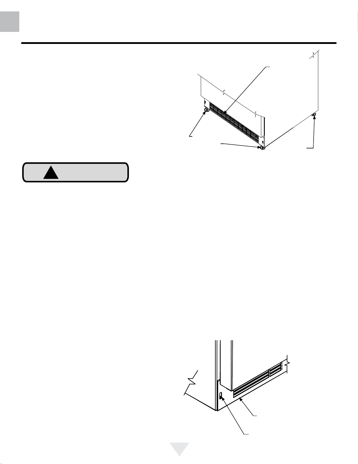
Cabinet Clearance
Ventilation is required from the bottom front of the appliance. Keep this area open and clear of any obstructions.
Adjacent cabinets and counter top can be installed around
the appliance as long as the front grille remains unobstructed.
!
CAUTION
Front Grille
Do not obstruct the front grille. The openings within the
front grille allow air to ow through the condenser heat exchanger. Restrictions to this air ow will result in increased
energy usage and loss of cooling capacity. For this reason
it is important this area not be obstructed and the grille
openings kept clean (See Figure 1). The use of a custom
made grille is not recommended as it may restrict air ow.
Front Grille,
keep this area
open.
Front Leveling
Legs
Figure 1
Rear
Leveling
Legs
Leveling Legs
Adjustable legs at the front and rear corners of the appli-
ance should be set so the unit is rmly positioned on the
oor and level from side to side and front to back. The
overall height of your appliance may be adjusted between
the minimum, 333⁄4" (85.7 cm), by turning the leveling leg in
(CW ↷) and the maximum, 343⁄4" (88.3 cm) by turning the
leveling leg out (CCW ↶).
To adjust the leveling legs, place the appliance on a solid
surface and protect the oor beneath the legs to avoid
scratching the oor. With the assistance of another person,
lean the appliance back to access the front leveling legs.
Raise or lower the legs to the required dimension by turning
the legs. Repeat this process for the rear by tilting the appliance forward using caution. On a level surface check the
appliance for levelness and adjust accordingly.
The front grille screws may be loosened and the grille adjusted to the desired height. When adjustment is complete
tighten the two front grille screws. (See Figure 2).
Figure 2
Front grille
Front grille screw
4

INSTALLING YOUR APPLIANCE
!
US
CA
WARNING
Figure 3
Do not remove
ground prong
Figure 4
Electrical Shock Hazard
• Do not use an extension cord with this appliance.
They can be hazardous and can degrade product
performance.
• This appliance should not, under any circumstances, be installed to an un-grounded electrical supply.
• Do not remove the grounding prong from the power
cord. (See Figure 3).
• Do not use an adapter. (See Figure 4).
• Do not splash or spray water from a hose on the
appliance. Doing so may cause an electrical shock,
which may result in severe injury or death.
Electrical Connection
A grounded 115 volt, 15 amp dedicated circuit is required.
This product is factory equipped with a power supply
cord that has a three-pronged, grounded plug. It must be
plugged into a mating grounding type receptacle in accordance with the National Electrical Code and applicable local codes and ordinances (see Figure 5). If the circuit does
not have a grounding type receptacle, it is the responsibility
and obligation of the customer to provide the proper power
supply. The third ground prong should not, under any circumstances, be cut or removed.
Figure 5
NOTE
Ground Fault Circuit Interrupters (GFCI) are prone to nuisance tripping which will cause the appliance to shut down.
GFCI’s are generally not used on circuits with power equipment that must run unattended for long periods of time, unless required to meet local building codes and ordinances.
5

US
CA
INSTALLING THE ANTI TIP DEVICE
FOR FREESTANDING INSTALLATIONS
!
WARNING
• ALL APPLIANCES CAN TIP
RESULTING IN INJURY.
Anti-Tip
Bracket
Leveling Leg
• INSTALL THE ANTI-TIP
BRACKET PACKED WITH
THE APPLIANCE.
• FOLLOW THE INSTRUCTIONS BELOW
Anti-Tip Device
!
WARNING
If your refrigerator is not located under a counter
top (free standing), you must use an anti-tip device
installed as per these instructions. If the refrigerator is
removed from its location for any reason, make sure
that the device is properly engaged with the anti-tip
bracket when you push the refrigerator back into the
original location. If the device is not properly engaged,
there is a risk of the refrigerator tipping over, with the
potential for property damage or personal injury.
NOTE
If installing on a concrete oor, concrete fasteners are
required, (not included with the anti-tip kit).
211⁄2"
(54.6 cm)
Bottom View of
Refrigerator
Front of cabinet
Figure 6
Step by step instructions for locating the
position of the bracket:
1) Decide where you want to place the refrigerator. Slide
it into place, being careful not to damage the oor, leaving
1" (2.5 cm) of clearance from the rear wall to allow room for
the anti-tip bracket.
2) Raise the rear leveling legs approximately 1⁄4" (6 mm) to
allow engagement with the anti-tip bracket. Level the unit
by adjusting all the leveling legs as required. Turning the
leveling leg counterclockwise will raise the unit and clockwise will lower the unit.
3) Make sure the refrigerator is in the desired location, then
mark on the oor the rear and side corner of the cabinet
where the anti-tip bracket will be installed. If the installation
does not allow marking the rear corner of the cabinet, then
make temporary lines on the oor marking the front corner
of the cabinet, excluding the door. Slide the refrigerator out
of the way. From the temporary line extend the sidewall line
back 211⁄2" (54.6 cm) as shown in Figure 7.
!
CAUTION
Any nished ooring should be protected with appropriate
material to avoid damage when moving the unit.
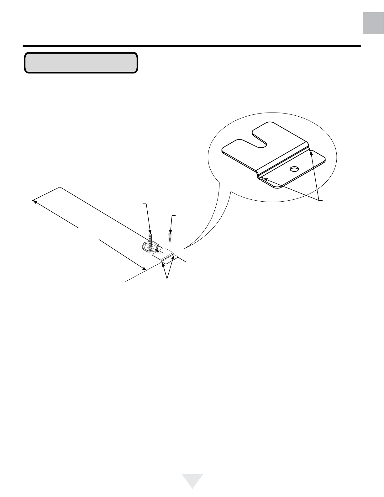
Floor Mount Installation
The anti-tip bracket is to be located on the oor in the left or
right rear corner of the refrigerator as shown in Figure 6.
4) Align the anti-tip bracket to the marks on the oor so
the side of the bracket lines up with the side of the cabinet
mark, and the "V" notches on the anti-tip bracket line up
with the end of the 211⁄2" (54.6 cm) line (Rear of cabinet line).
5) Fasten the anti-tip bracket to the oor using the supplied
screw. (See Figure 7).
6) Slide the cabinet back into position, making sure the rear
cabinet leveling leg slides under the anti-tip bracket engaging the slot.
6
INSTALLING THE ANTI TIP DEVICE
FOR FREESTANDING INSTALLATIONS
NOTE
When the oor mounted anti-tip bracket is used the minimum adjusted height of the cabinet is increased by
3
⁄8" (9 mm).
US
CA
Front of cabinet line
Side of cabinet line
211⁄2"
(54.6 cm)
Figure 7
Rear Leveling leg
Rear of cabinet line
Screw
"V" notches
in bracket
Figure 7a
"V" notches
in bracket
7
US
CA
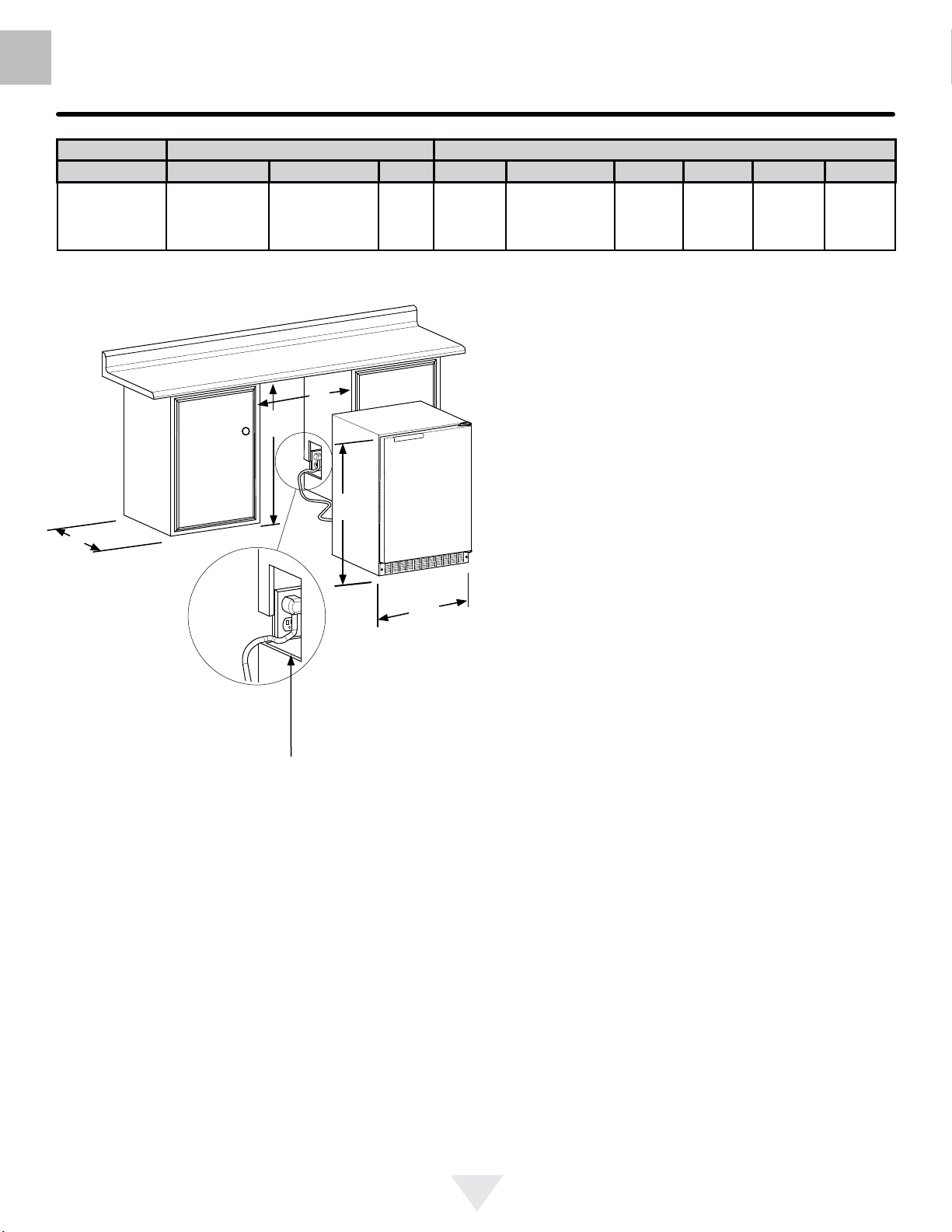
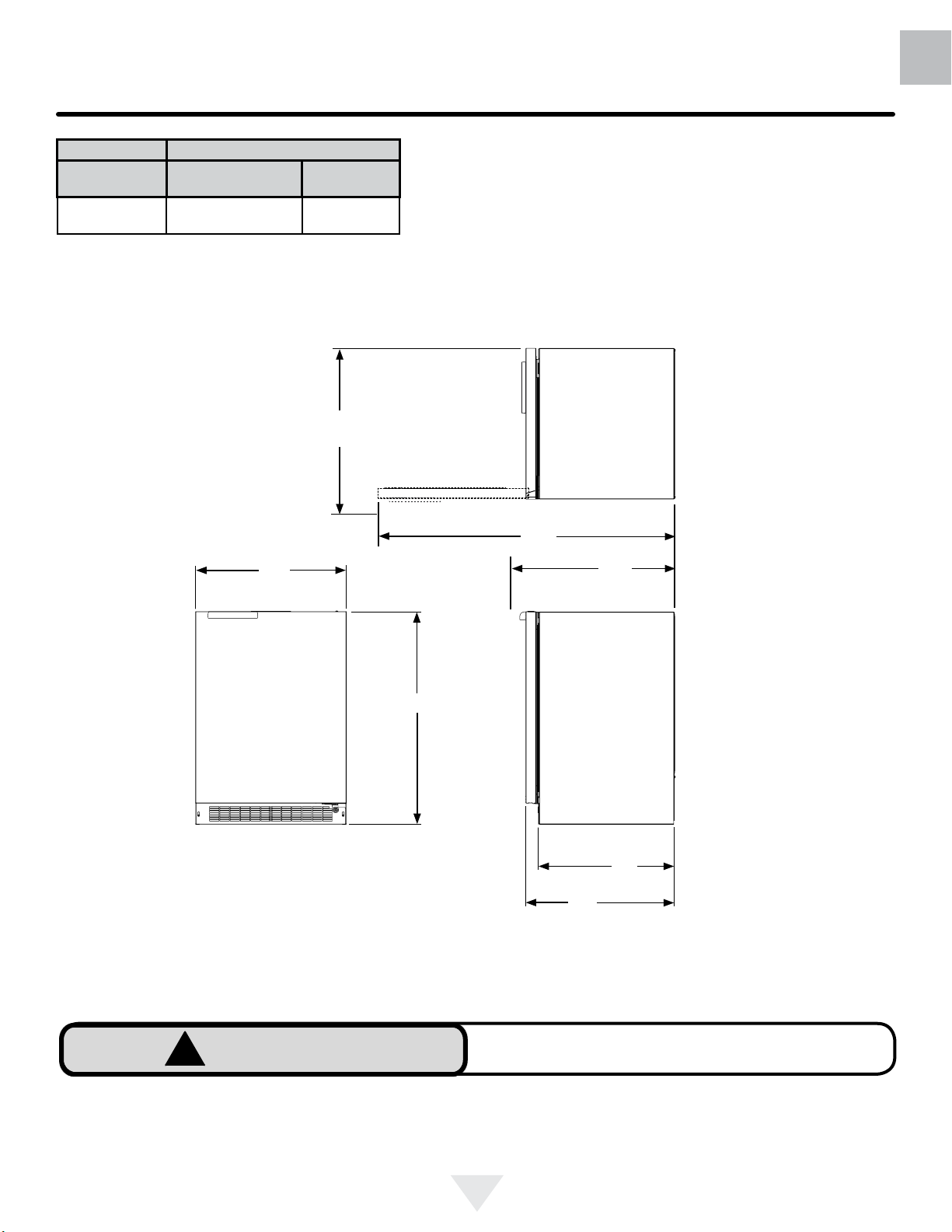
PRODUCT DIMENSIONS
ROUGH-IN OPENING DIMENSIONS CABINET DIMENSIONS
MODEL "A" "B" "C" "D" "E" "F" "G" "H" "J"
1
24
⁄4" (61.6 cm)
RF24RE3
RF24LE3
Figure 8
24 ½" (62 cm)
(with optional DCS
side trim kit)
**34" to 35"
(86.4 to 88.9 cm)
"A"
"B"
*
237⁄8"
(60.7 cm)
333⁄4" to 343⁄4"
(85.7 to 88.3 cm)
2323⁄32"
(60.2 cm)
267⁄32"
(66.6 cm)
4613⁄32"
(117.9 cm)
261⁄4"
(66.7 cm)
"E"
"C"
"D"
Figure 8a
If necessary to gain clearance inside the rough-in opening a hole can be cut through the adjacent cabinet and
the power cord routed through this hole to a power outlet.
Another way to increase the available opening depth is to
recess the power outlet into the rear wall to gain the thickness of the power cord plug.
* Depth dimension of rough-in opening may vary depending on each individual installation. To recess entire door "F"
dimension plus 1" (2.5 cm) for thickness of power cord plug
is required.
** Minimum rough-in opening required is to be larger than
the adjusted height of the cabinet.
*** A grounded 15 amp dedicated circuit is required. Follow
all local building codes when installing electrical and appliance.
8
MODEL
RF24RE3
RF24LE3
PRODUCT DATA
ELECTRICAL
REQUIREMENTS ***
115V/60Hz/15A
PRODUCT DIMENSIONS
PRODUCT
WEIGHT
140 lbs
(63.6 kg)
"J"
US
CA
"D"
"E"
Figure 9
"H"
"G"
211⁄2"
(54.6 cm)
"F"
!
WARNING
Floor mount Anti-tip Bracket must be installed for freestanding applications. Not required for built in applications.
9
US
CA
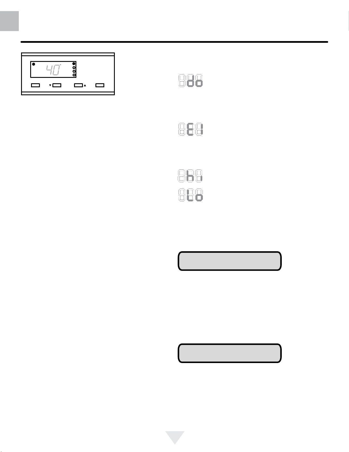
USING YOUR ELECTRONIC CONTROL
Alarm
F
Set
Press and Hold Press and Hold
Colder Warmer
ON/OFF
Figure 10
close-up of
control
Starting your refrigerator
Plug the refrigerator power cord into a wall outlet. Your
refrigerator will begin cooling after power is applied.
If your refrigerator does not start, check that the refrigerator
is turned on and the set temperature is cold enough.
Turning your refrigerator ON or OFF
If the refrigerator is on, the refrigerator temperature will be
shown on the display. To turn the refrigerator off, press and
hold the "ON/OFF" button for three seconds. "OFF" will appear on the display.
If the refrigerator is not on, "OFF" will be shown on the
display. To turn the refrigerator on, press and hold the "ON/
OFF" button for three seconds. The refrigerator temperature will be shown on the display.
Set temperature
To set the refrigerator temperature, press and hold the
"SET" button. When the "SET" button is pressed, the
display will show the set temperature. While holding the
"SET" button, press the "WARMER" or "COLDER" buttons
to adjust set temperature.
Refrigerator operation
The available temperature range of the refrigerator is 34° to
42°F (1° to 6°C).
It may take up to 24 hours for your refrigerator to reach
desired temperature. This will depend on amount of content
loaded and number of door opening and closings.
Alarms
Your digital display function will monitor refrigerator function
and alert you with a series of audible and visual alarms.
• Door Ajar Alarm: If the door has been left
open for over ve minutes, the alarm will
sound in one second intervals. The display
panel will ash "do" and the Alarm LED located at the top
left of the display below the word "Alarm" will be illuminated. This will stop as soon as the door is closed.
• Temperature Sensor Fault: If the controller detects that the temperature sensor is not
properly functioning, a temperature sensor
alarm will sound in one second intervals. "E1" will ash on
the display panel and the Alarm LED located at the top left
of the display below the word "Alarm" will be illuminated.
• High and Low Temperature Alarm: If your
unit reaches an unacceptable temperature
outside of your set-point, the alarm will sound
in (1) second intervals. The display panel will
ash either "Hi" or "Lo" depending upon the
condition and the Alarm LED light at the top
left of the display below the word "Alarm" will be illuminated. These alarms indicate that the compartment temperature has moved 10° or more from the set point for more
than 1 hour duration. The alarm will remain active until the
condition is corrected.
NOTE
During initial appliance start-up, the high temperature alarm
may sound until the interior temperature reaches set point.
The high temperature alarm can also occur if the door remains open during an extended period of time (i.e. cleaning
or door ajar alarm condition), high usage or loading with
warm product. After a high temperature alarm condition check
all perishables to ensure they are safe for consumption.
Alarm Mute
Press any key to mute the audible portion of an alarm.
For best results allow refrigerator to "pull down" to desired
set temperature before loading. Once contents are loaded,
allow at least 48 hours for temperature to stabilize before
making any adjustments to the set temperature.
NOTE
This action will only mute the alarm. If the condition that
caused the alarm continues, the alarm code will continue to
ash and will sound for 20 seconds every 60 minutes.
10
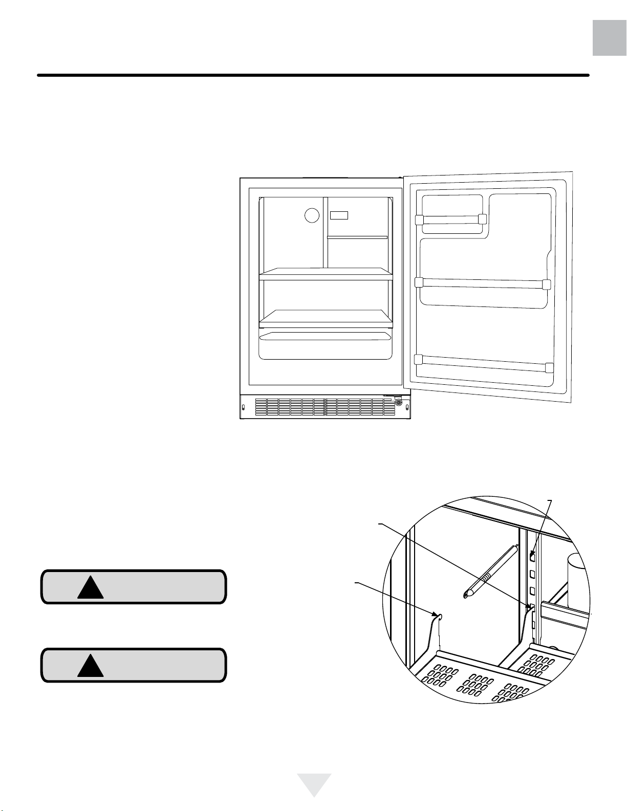
INTERNAL LAYOUT
Loading Tips and Suggestions
Your appliance is equipped with a cantilever shelf system
which provides maximum adjust ability and customizing of
the shelving arrangements listed below.
Refrigerator:
24" (61 cm) Wide Models:
With a solid door. Figure 11.
Your product comes with:
1 half width perforated stainless
steel cantilever shelf.
2 full width perforated stainless
steel cantilever shelves.
1 half width door storage rack.
2 full width door storage racks.
US
CA
To Add or Remove a Shelf
Remove stored product from the shelf. Do not try to remove
a loaded shelf from the appliance. Grasp the shelf front with
both hands, rotate the front upward and lift out. (See Figure
11). To install a shelf insert the shelf in the appliance and
insert the top hooks into the shelf support slots and drop the
shelf down so the hooks drop over the bottom of the slots.
!
CAUTION
Never try to move a loaded shelf, remove everything from the
shelf before moving. Use both hands when moving the shelf.
!
CAUTION
Make sure your cantilever shelf is secure on the shelf supports by pressing down on the shelf before loading.
Figure 11
Shelf support
slot
Installed shelf
tang
Rear tang
(hook) on
shelf
Figure 12
11
US
CA
CARE AND CLEANING
Front Grille
Be sure that nothing obstructs the required air ow openings in front of the cabinet. At least once or twice a year,
brush or vacuum lint and dirt from the front grille area (see
page 4).
!
CAUTION
SHOCK HAZARD: Disconnect electrical power from the
appliance before cleaning with soap and water.
Cabinet
The stainless steel cabinet can be washed with mild soap
and water and thoroughly rinsed with clean water. See
"Stainless Steel Maintenance" on page 14.
Interior
Wash interior compartment with mild soap and water. Do
NOT use an abrasive cleaner, solvent, polish cleaner or
undiluted detergent.
Care of Appliance
1. Avoid leaning on the door, you may bend the door
hinges or tip the appliance.
2. Exercise caution when sweeping, vacuuming or mopping near the front of the appliance. Damage to the
grille can occur.
3. Periodically clean the interior of the appliance as
needed.
In the Event of a Power Failure
If a power failure occurs, try to correct it as soon as possible. Minimize the number of door openings while the
power is off so as not to adversely affect the appliance's
temperature.
Light assembly replacement
All models use LED lamps to illuminate the interior of the
appliance. This component is very reliable, but should one
fail, contact a qualied service technician for replacement
of the LED.
12
 Loading...