

Page 1
MB200
Direct Thermal Printer
OPERATOR MANUAL
PN 9001126A
Page 2

SATO America, Inc.
10350A Nations Ford Road
Charlotte, NC 28273
Main Phone: (704) 644-1650
Technical Support Hotline: (704) 644-1660
Technical Support Fax: (707) 644-1662
E-Mail: satosales@satoamerica.com
www.satoamerica.com
All rights reserved. No part of this document may be reproduced or issued to third parties in any form
whatsoever without the express permission of SATO America, Inc. The materials in this document is
provided for general information and is subject to change without notice. SATO America, Inc. assumes no
responsibilities for any errors that may appear.
Warning: This equipment complies with the requirements in Part 15 of FCC rules for a Class B computing
device. Operation of this equipment in a residential area may cause unacceptable interference to radio
and TV reception requiring the operator to take whatever steps are necessary to correct the interference.
© Copyright 2003
SATO America, Inc.
Page 3

TABLE OF CONTENTS
INTRODUCTION
General Description 1-2
Theory Of Operation 1-2
Switches And Indicators 1-3
Connection Ports 1-3
TECHNICAL DATA
Physical Characteristics 2-1
Power 2-1
Enviromental 2-1
Print 2-1
Media 2-1
Sensing 2-2
Interface Modules 2-2
Processing 2-2
Character Font Capabilities 2-2
Barcode Capabilities 2-2
Regulatory Approvals 2-3
INTERFACE SPECIFICATIONS
Interface Types 3-1
Factory Defaults 3-1
Interface Configuration 3-1
RS232 Serial Interface 3-2
TTL Interface 3-3
Infrared Data (IrDA) Interface 3-4
ACK/NAK Protocol 3-5
Receive Buffer 3-6
CONFIGURATION
Dip Switch Complex DSW1 4-2
Dip Switch Complex DSW2 4-3
Dip Switch Complex DSW3 4-3
Configuration Modes 4-4
Normal Mode 4-5
Sleep Mode 4-6
Auto Power Off Mode 4-7
Dispenser Mode 4-8
User Test Print Mode 4-9
Default Settings Mode 4-10
Hex Dump Mode 4-11
Factory Clear Mode 4-12
Font Download Mode 4-13
Program Download Mode 4-15
TROUBLESHOOTING
Error Signals 5-1
Troubleshooting Table 5-1
RS232 Serial Interface Troubleshooting 5-2
Diagnostic Label Printing 5-3
PN 9001126A
Page 4

MAINTENANCE
Cleaning 6-1
Platen Roller 6-3
Drive Motor 6-4
Drive Gear 6-6
Feed Roller 6-7
Main Circuit Board 6-8
IrDA Sensor 6-10
Gap Sensor 6-11
Eye-Mark Sensor 6-13
Head-Open Switch 6-15
ADJUSTMENT PROCEDURES
Position Adjustments 7-1
PN 9001126A
Page 5

INTRODUCTION
This manual is laid out consistent with the product discussed and provides all of the information
required for general printer configuration, troubleshooting, and maintenance. For specialized
programming, refer to the Programming Manual located on the utility CD-ROM.
Step-by-step maintenance instructions are provided with typical problems and solutions. It is
recommended that you become familiar with each section before installing and maintaining the
printer.
This manual also incorporates the use of special information boxes. Examples of these boxes
and the type of information provided in each, are below.
WARNING: PROVIDES INFORMATION THAT, IF UNHEEDED, MAY
RESULT IN PERSONAL INJURY.
CAUTION: PROVIDES INFORMATION THAT, IF UNHEEDED, MAY
RESULT IN EQUIPMENT DAMAGE.
NOTE: Provides helpful hints to assist in performing the tasks at hand.
1
A comprehensive Table Of Contents provided at the front of this manual facilitates rapid
movement within. The contents identify the different unit sections and their respective subsections. Each references the page number of their commencement.
The pages of this manual has embedded headers and footer to assist the user in identifying his
or her exact position within the manual. The header provides the section number followed by its
name. The footer identifies the product on the left, the manual’s part number in the center, and
the page number to the right side of the page.
Page inumeration is two-part with each separated by a hyphen. The first character set references
the section number and the second identifies the page number. Page numbers begin with the
numeral (1) one at the commencement of a new section and ascends sequentially.
SATO MB200 Operator Manual PN: 9001126A Page 1-1
Page 6
Unit 1: Introduction
GENERAL DESCRIPTION
The MB400 is a compact, transportable printer designed for frequent, but intermittant use. Its
direct thermal print head not only allows high performance two-color printing, but also clear
barcode printing. It can also enlarge and print various types of fonts and Kanji characters in a free
layout.
Its ABS housing with protective rubber boots provide a durable, impact-resistant product. Oversized control buttons and shoulder strap ensures ease of use during transport. An intergrated
dispenser enables application of labels upon print. Rechargeable battery packs and a DC power
transformer ensures operation anywhere, under any conditions. An automatic power off function
turns the printer off after the last print.
Dispenser unit
Dispense /
Continuous
switch lever
Power switch
Protective case
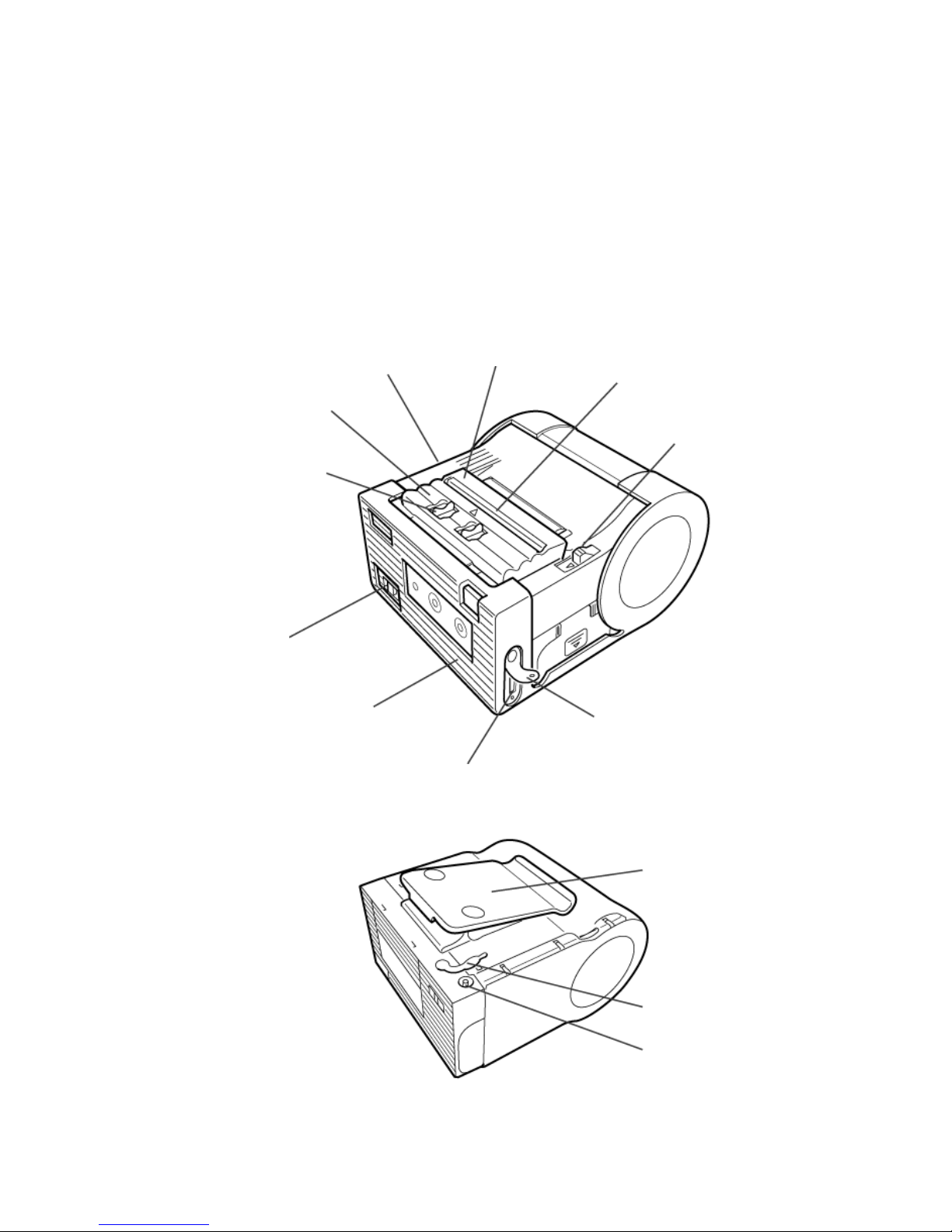
Figure 1-1a, Primary Features & Components
Front cover
Label exit
Cutter
Cover Open/
Close lever
Interface cover
Interface connector (RS-232C)
SATO MB200 Operator Manual PN 9001126A Page 1-2
Belt hook
DC input jack cap
DC input jack
Figure 1-1b, Primary Features & Components
Page 7
Unit 1: Introduction
SWITCHES AND INDICATORS
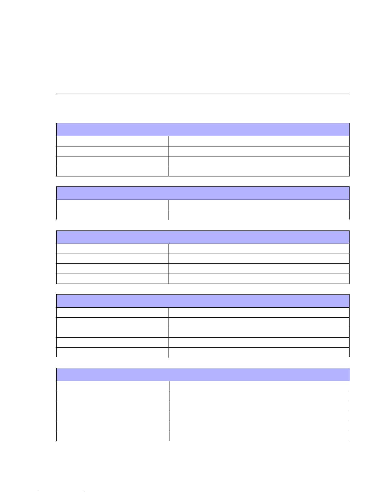
The table below identifies and defines printer switches and indicators for operator interface. The
accompanying graphics display their locations and appearance
SWITCHES
Power Button Two position on/off switch that controls power flow to the system.
Print Button Two position on/off button that activates and deactivates print action.
Feed Button Two position on/off button that activates and deactivates feed action.
INDICATORS
Status LED Indicates the systems’ operational status.
DIP SWITCHES
1-1, 1-3 Interface settings.
1-2 Reserved.
1-4 Auto Feed function.
1-5 Head Check function.
1-6, 1-7, 1-8 Factory Clear and Error Message assignment.
POTENTIOMETERS
VR1 Eye-Mark Sensor adjustment.
VR2 Gap Sensor adjustment.
VR3 Print Position adjustment.
VR4 Print Darkness adjustment.
CONNECTION PORTS
These ports are externally accessable and permit connection of the accessories and
attachments necessary for printer programming and operation. Not listed here, are the
connection ports of circuit boards not externally accessable.
CONNECTION PORTS
DC Supply Port Connector permits 115V, 50/60 Hz supply via supplied cord.
Test Terminal For connecting the TP Test Module.
SATO MB200 Operator Manual PN 9001126A Page 1-3
Page 8
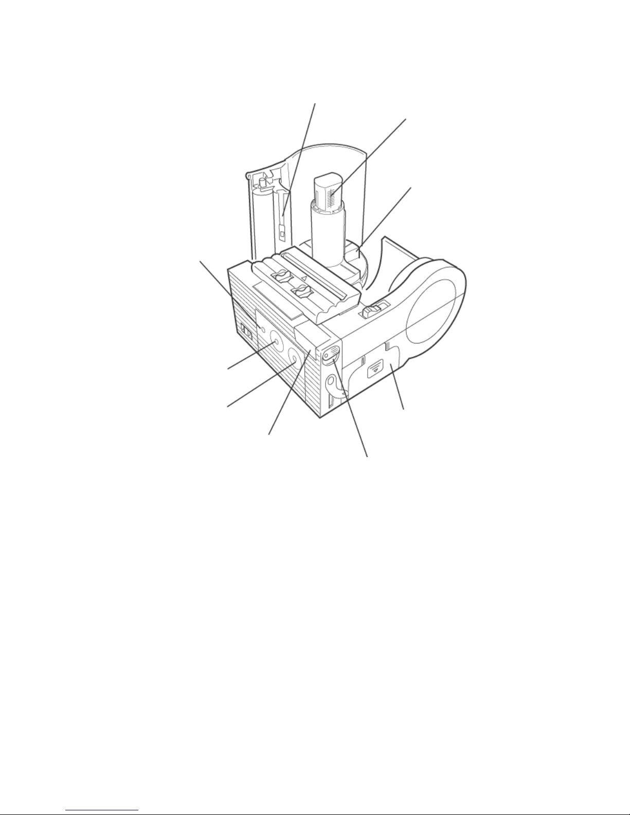
Unit 1: Introduction
Status
indicator
(LED)
Label guide (Left)
Label width scale
Label guide (Right)
Print key
Feed key
Battery cover
IrDA filter
IrDA angle lever
Figure 1-1c, Primary Features & Components
SATO MB200 Operator Manual PN 9001126A Page 1-4
Page 9
2
TECHNICAL DATA
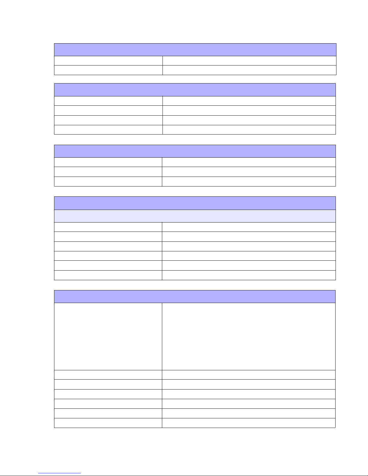
All technical data deemed pertinent has been tabulated below for quick reference. Find the
relative section header and then locate the specific type of technical data in the left column.
PHYSICAL CHARACTERISTICS
Width 3.94 Inches (100 mm)
Height 2.93 Inches (74.5 mm)
Depth 5.04 Inches (128 mm)
Weight .948 Pounds (430 g)
POWER
Adapter Voltage Autoswitching 100-240 VAC, 60 Hz
Battery Supply Pack Type Lithium Ion Battery 1500mAh, 7.2v
ENVIRONMENTAL
Operating Temperature 41° to 104°Farenheit (5° to 40°C)
Storage Temperature 23° to 113°Farenheit (-5° to 45°C)
Storage Humidity 20 to 80% Non-Condensing
Operating Humidity 20 to 80% Non-Condensing
PRINT
Type Direct Thermal
Speed 2.46 Inches Per Second (62.5 mm/s)
Resolution 203 Dots Per Inch (8 d/mm)
Maximum Print Width 1.9 Inches (48 mm)
Maximum Print Length 6.3 Inches (160 mm)
MEDIA
Type Super Sensitive, Techno, Synthetic, 2-Color, Journal, Linerless
Minimum Width 1.1 Inches (28 mm)
Maximum Length 6.4 Inches (163 mm)
Maximum Width 2.3 Inches (58 mm)
Type Roll (Face out)
Maximum Caliper 0.007 Inches (0.18 mm)
SATO MB200 Operator Manual PN: 9001126A Page 2-1
Page 10
Unit 2: Technical Data
MEDIA
Maximum Roll Diameter 2.3 Inches (58 mm)
Minimum Core Diameter 1.04 Inches (26.5 mm)
INTERFACE MODULES
Serial Port RS232C/TTL (switchable)
Standard Infrared
Special RF
Special Wireless / 802.11B
PROCESSING
CPU 32 Bit RISC
FLash ROM 4 Mega-Bytes
SDRAM 16 Mega-Bytes
CHARACTER FONT CAPABILITIES
MATRIX FONTS
XB Font 48 dots W x 48 dots H
XS Font 17 dots W x 17 dots H (Universal Condensed Bold)
XM Font 24 dots W x 24 dots H (Universal Condensed Bold)
POP 80 dots W x 133 dots H
Kanji 16, 22, 24 dots W x 16, 22, 24 dots H
JIS 1 & 2 (optional)
BAR CODE CAPABILITIES
Linear Bar Codes
Two Dimensional
Ratios 1:2, 1:3, 2:5, User definable bar widths
Bar Height 4 to 999 dots, User progammable
Rotation 0, 90, 180, 270 Degrees
Sequential Numbering Sequential numbering of both numerics and bar codes
Custom Characters RAM storage for special characters
Graphics Full dot addressable graphics
EAN-8, 13
CODABAR
Code 39, 93, 128
Interleaved 2, 5
UPC-A, .E
Codabar
PDF417
QR Code
Maxicode (optional)
SATO MB200 Operator Manual PN 9001126A Page 2-2
Page 11

Unit 2: Technical Data
REGULATORY APPROVALS
Safety UL, CE, TUV, FCC-B
Noise VCCI-B
Electrical Resistance Level 2
SATO MB200 Operator Manual PN 9001126A Page 2-3
Page 12
INTERFACE SPECIFICATIONS
This unit presents the printer interface specifications. These specifications include detailed
information on how to properly interface the printer with the host system. The four acceptable
interface methods are:
• RS232C Asynchronous Serial
• TTL Asynchronous Serial
• IrDA Infrared
• Bluetooth Wireless
• Wireless LAN 802.11B
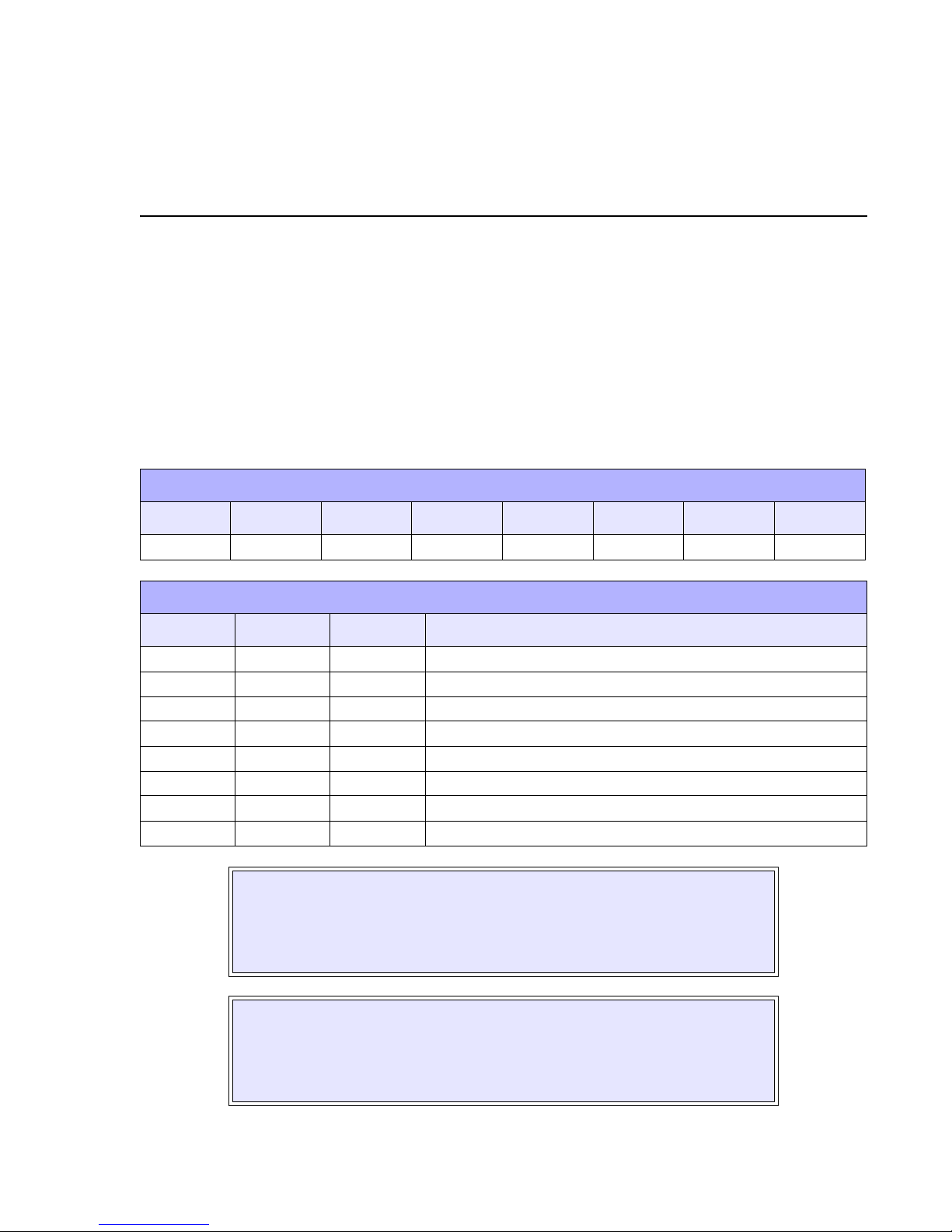
FACTORY DEFAULTS
DSW 1-1 DSW 1-2 DSW 1-3 DSW 1-4 DSW 1-5 DSW 1-6 DSW 1-7 DSW 1-8
IF Specific IF Specific IF Specific On On Off Off Off
INTERFACE CONFIGURATION
DSW 1-1 DSW 1-2 DSW 1-3 OPERATIONAL MODE
3
Off Off Off RS-232C
On Off Off TLL
Off On Off IrDA
On On Off Bluethooth (mode 1 using PIN code)
Off Off On RS-232C, IrDA
On Off On TTL, IrDA
Off On On Bluetooth (mode 2 no authentification)
On On On Wireless LAN (802.11B)
WARNING: NEVER CONNECT OR DISCONNECT INTERFACE CABLES
(OR USE A SWITCH BOX) WITH POWER APPLIED TO EITHER THE
HOST OR THE PRINTER. THIS MAY CAUSE DAMAGE TO THE
INTERFACE CIRCUITRY IN THE PRINTER/HOST AND IS NOT COVERED
BY WARRANTY.
NOTE: Some hosts monitor the Request-To-Send (RTS) signal (pin 4 of 25)
to determine if the printer is ready to receive data. Since the printer does not
generate this signal, the RTS line must be held true (high) in order to allow
communication. This can be performed by connecting the RTS pin to the
Clear-To-Send (CTS) signal (pin 5 of 25).
SATO MB200 Operator Manual PN: 9001126A Page 3-1
Page 13

Unit 3: Interface Specifications
RS232 SERIAL INTERFACE
This High Speed Serial Interface is a Plug-In Interface Module that can be connected to the
printer by the user. The only difference between this interface and the TTL is their signal levels
and cable pinouts.
RS232C SPECIFICATIONS
Asynchronous ASCII Half-duplex communication
Bi-Directional Communication
Data Transmission Rate 4800, 9600, 19200, 38400 bps
Data Length 8 bit (selectable)
Stop Bit 1 bit (fixed)
Parity Bit ODD, EVEN, NONE (selectable)
Codes Used ASC II Character Codes, JIS Kanji Codes
Control Codes STX (02H), ETX (03H), ACK (06H), NAK (15H)
Connector Special
Cable Special
Signal Levels High = +3V to +12V, Low = -3V to -12V
INTERFACE SIGNALS
PIN DIRECTION SIGNAL DEFINITION
1 Reference SG (Signal Ground)
2 To Host SD (Sending Data) - Data to the host computer from the printer.
3 To Printer RD (Receive Data) - Data to the printer from the host computer.
4 --- Reserved
5 --- Reserved
6 Reference SG (Signal Ground)
7 --- Reserved
8 --- Reserved
9 --- Reserved
10 --- Reserved
11 --- Reserved
12 Reference SG (Signal Ground)
SATO MB200 Operator Manual PN 9001126A Page 3-2
Page 14

Unit 3: Interface Specifications
TTL INTERFACE
The only difference between this interface and the RS232C is their signal levels and cable
pinouts.
TTL SPECIFICATIONS
Asynchronous ASCII Half-duplex communication
Data Transmission Rate 4800, 9600, 19200, 38400 bps
Data Length 8 bit (selectable)
Stop Bit 1 bit (fixed)
Parity Bit ODD, EVEN, NONE (selectable)
Codes Used ASC2 Character Codes, JIS Kanji Codes
Control Codes STX (02H), ETX (03H), ACK (06H), NAK (15H)
Connector Special
Cable Special
Signal Levels High = +2.0V to +3.3V Low = -0.5V to -0.8V
INTERFACE SIGNALS
PIN DIRECTION SIGNAL DEFINITION
1 Reference SG (Signal Ground)
2---Reserved
3---Reserved
4---Reserved
5---Reserved
6 Reference SG (Signal Ground)
7---Reserved
8 To Host SD (Sending Data) - Data to the host computer from the printer.
9 To Printer RD (Receive Data) - Data to the printer from the host computer.
10 --- Reserved
11 --- Reserved
12 Reference SG (Signal Ground)
WARNING: NEVER CONNECT OR DISCONNECT INTERFACE CABLES
(OR USE A SWITCH BOX) WITH POWER APPLIED TO EITHER THE
HOST OR THE PRINTER. THIS MAY CAUSE DAMAGE TO THE
INTERFACE CIRCUITRY IN THE PRINTER/HOST AND IS NOT COVERED
BY WARRANTY.
SATO MB200 Operator Manual PN 9001126A Page 3-3
Page 15

Unit 3: Interface Specifications
INFRARED DATA (IRDA) INTERFACE
Infrared communications is based on technology which is similar to entertainment remote control
devices used in homes today. This technology offers a convient, interoperable, low power, and
reliable way to connect computer and printer without the use of cables. The half duplex, serial
data interconnection capabilities supports walk up point to point use.
The infrared transmission of print data is transferred from the terminal to the printer in four
phases: (1) Connection, (2) Printer Status Check, (3) Data Transfer, (4) Disconnection.
IRDA SPECIFICATIONS
Asynchronous ASCII Half-duplex communication
Ready/Busy Hardware Flow Control
Pin 20, DTR Control
Pin 4, RTS Error Condition
X-On/X-Off Software Flow Control
Bi-Directional Communication
Data Transmission Rate 9600, 19200, 38400, 57600 bps
Data Length 8 bit (selectable)
Stop Bit 1 bit (fixed)
Parity Bit NONE
Codes Used ASC2 Character Codes, JIS Kanji Codes
Control Codes STX (02H), SYN (16H), EXT (03H), DLE (10H)
Communication Time Time-Out: 5 seconds, Retry: over 500 milliseconds.
Receiving Type Single item.
Signal Levels
Compliance HP-SIR Type of IrDA Standard IrSIR version 1.2. Upper levels are
not implemented.
CONTROL CODE - DLE must be added just prior to SYN, STX, or ETX. DLE should also be
added if the same code with DLE is included in the transferred message. With these two
methods, any control code can be used in the transferred message.
FORMAT - All transferred messages from phase 1 to phase 4 take the following format to form
the BCC calculation area. BCC is a 2-byte 16 bit SUM and the lower byte is placed at the head.
The calculation of BCC is the sum of the header and data parts.
HEADER - The Header includes the type of transferred message (cmd) and packet number (cnt).
However, some headers do not have a packet number.
Cmd is a single byte code that represents the type of packet. Cnt is only added when the packet
is any of Data Response, Data Transmission Complete, or Transmission Termination Response,
and represents the data packet number. The number begins from 1 and increments by one,
every time the terminal receives a new packet. The printer responds wit the Response packet by
putting the received number in it. Confirm the number matches with the terminal side.
Also, specify the total number of transferred packet for the Data Transmission Complete/
Transmission Complete Response packets.
SATO MB200 Operator Manual PN 9001126A Page 3-4
Page 16

Unit 3: Interface Specifications
MESSAGE FORMATS
SSS, YYT, NNX Header, variable length Data, variable length EXT BB, CC, CC, Ih
HEADER PACKETS
Connection Request/Connection Response packet 40H
Printer Status Inquiry/Printer Status Response packet 14H
Data Header/Response packet 03H
Data/Data Response packet 15H
Data Transmission Complete/Transmission Complete Response packet 17H
Disconnection Request/Disconnection Response packet 41H
DATA ITEMS
SPACE(13) Dummy data.
null(4) Dummy data.
size(4) Data size.
len(2) Data block length (maximum 256 bytes).
block Data block (maximum 256 bytes).
status(4) Status
id(6) Printer ID (ASC2 specification).
flag Packet status flag
ACK/NAK PROTOCOL
Bi-Directional ACK/NAK protocol is used for error control. In a normal transmission sequence
when the transmission is received, the printer will return an ACK (06H) signifying that it was
received without a transmission error. After the transmission command structure has been
analyzed, a status byte is returned to the host. This status byte informs the host of the validity of
the command structure.
If the command structure is error free, the printer proceeds with the print operation. When the
print operation is completed, a Printer Status message is returned to the host. If an error was
detected during the initial transmission sequence, a NAK (15H) will be returned signalling to the
host that the received transmission contained errors and must be resent. If the returned Status
byte indicates a command structure error, the error must then be corrected before the print data
is resent to the printer.
A valid transmission to the printer must be bounded by an STX/ETX pair, with the STX (02H)
signifying the start of the Print Data and ending with an ETX (03H) signifying the end.
SATO MB200 Operator Manual PN 9001126A Page 3-5
Page 17

Unit 3: Interface Specifications
RECEIVE BUFFER
The data stream is received from the host to the printer one job at a time. This allows the
software program to maintain control of the job print queue so that it can move a high priority job
in front of ones of lesser importance.
The printer receives and prints one job at a time. If a print job exceeds the buffer size,
transmission will be rejected by the printer. Flow control protocols to throttle transmission are not
used. Error conditions that occur during the Print Data transmission will cause the printer to
return a NAK.
SATO MB200 Operator Manual PN 9001126A Page 3-6
Page 18

PRINTER CONFIGURATION
The printer may be configured for specific jobs via the operator and interface panels. The
operator panel is located on the face of the front housing cover and is comprised of a power
switch, Print button, Feed button, and a Status LED.
The interface panel is located under the hinged cover beneath the operator panel. The interface
panel is comprised of three eight dip switch complexes, three potentiometers, and an interface
connector located to the right.
4
Print & Feed Buttons
LED
Power Switch
Potentiometers
DSW1 (eight switch complex)
RS232 Interface Connector
Figure 4-1, Interface Panel
SATO MB200 Operator Manual PN: 9001126A Page 4-1
Page 19

Unit 4: Configuration
DIP SWITCH COMPLEX DSW1
The following tables provide guidance on the enabling/disabling of various functions and
features. This chapter deals solely with dip switch complex DSW1.
FACTORY DEFAULTS
DSW 1-1 DSW 1-2 DSW 1-3 DSW 1-4 DSW 1-5 DSW 1-6 DSW 1-7 DSW 1-8
IF Specific IF Specific IF Specific On On Off Off Off
INTERFACE CONFIGURATION
DSW 1-1 DSW 1-2 DSW 1-3 OPERATIONAL MODE
Off Off Off RS-232C
On Off Off TLL
Off On Off IrDA
On On Off Bluetooth (mode 1 using PIN code)
Off Off On RS232C, IrDA
On Off On TTL, IrDA
Off On On Bluetooth (mode 2 no authentification)
On On On Wireless LAN (802.11B)
AUTOFEED & HEAD CHECK CONFIGURATION
DSW 1-4
DSW 1-5
Off: Manual Feed or Factory Offset / On: Auto Feed or Print Darkness adjustment
Head Check - Off: Disabled / On: Enabled
MODE CONFIGURATION
DSW 1-6 DSW 1-7 DSW 1-8 OPERATIONAL MODE
Off Off Off Factory Clear Mode w/o counter clear
On Off Off Factory Clear Mode w/ head counter clear
Off On Off Factory Clear Mode w/ head counter & factory counter clear
On On Off Reserved
Off Off On Dispenser Operation
On Off On Hex Dump Mode
Off On On Font Download
On On On Program Download
NOTE: Some button/key combinations are required when altering
some dip switches. Refer to the relative mode in the Configuration
Modes chapter to follow for guidance.
SATO MB200 Operator Manual PN 9001126A Page 4-2
Page 20

Unit 4: Configuration
DIP SWITCH COMPLEX DSW2
The DSW2 dip switch complex is used for configuring the IrDA Interface. For instructions on this
configuration, contact SATO Technical Support for guidance. The factory defaults are provided
below in case of accidental alteration of their settings.
CAUTION: DO NOT CHANGE THE DEFAULT SETTINGS
UNLESS DIRECTED OTHERWISE.
NOTE: The IrDA Interface for this unit is not compatible with LPT or
COM.
FACTORY DEFAULTS
DSW 2-1 DSW 2-2 DSW 2-3 DSW 2-4 DSW 2-5 DSW 2-6 DSW 2-7 DSW 2-8
Off Off Off Off Off Off Off Off
DIP SWITCH COMPLEX DSW3
Dip switch complex DSW3 allows the specification of a Bluetooth interface frequency. For
instructions on this configuration, contact SATO Technical Support for guidance. The factory
defaults are provided below in case of accidental alteration of their settings.
CAUTION: DO NOT CHANGE THE DEFAULT SETTINGS
UNLESS DIRECTED OTHERWISE.
FACTORY DEFAULTS
DSW 3-1 DSW 3-2 DSW 3-3 DSW 3-4 DSW 3-5 DSW 3-6 DSW 3-7 DSW 3-8
On On On On On On On On
SATO MB200 Operator Manual PN 9001126A Page 4-3
Page 21

Unit 4: Configuration
CONFIGURATION MODES
This section provides an overview of the various configuration modes of the operation menu. Refer to Figure 5-2 for initial activity and then advance to its relative section that follows.
Refer to
POWER
Normal Mode
Normal Mode
Section
Figure 5-3
STATUS LED
flashes red,
illuminates
green
STATUS LED
blinks green
FEED + POWER
Cover Open
+ PRINT
+ POWER
DSW1-6 = ON
DSW1-7 = OFF
DSW1-8 = ON
POWER
Sleep Mode
Auto Power Off Mode
Dispenser Mode
User Test Print
Mode
Default Setting
Mode
Hex Dump
Mode
Refer to
Sleep Mode
Section
Figure 5-4
Refer to
Auto Power
Off Mode
Figure 5-5
Refer to
Dispenser
Mode
Section 5-6
Refer to
Test Print
Mode
Figure 5-7
Refer to
Default
Setting Mode
Figure 5-8
Refer to Hex
Dump Mode
Figure 5-9
SATO MB200 Operator Manual PN 9001126A Page 4-4
DSW1-6
DSW1-7
DSW1-8
Cover Open
PRINT + FEED + POWER
DSW1-6 = OFF
DSW1-7 = ON
DSW1-8 = ON
POWER
DSW1-6 = ON
DSW1-6 = On
DSW1-7 = ON
DSW1-7 = On
DSW1-8 = ON
DSW1-8 = On
POWER
POWER
Figure 4-2, Configuration Modes
Factory Clear
Mode
Font Download
Mode
Program Download
Mode
Refer to
Factory Clear
Mode
Figure 5-10
Refer to Font
Download
Figure 5-11
Refer to
Program
Download
Figure 5-12
Page 22

Unit 4: Configuration
NORMAL MODE
Figure 5-3 provides the specific sequence of events required by the operator, the printer, and the
printer’s software for normal mode congiguration.
POWER
STATUS LED
flashes red,
flashes green
STATUS LED
blinks green
PRINT
STATUS LED
illuminates
green
Prints then
positions for the
next label.
Online
Offline Status/
Journal Printing
FEED
One label is
printed
Offline
STATUS LED
turns off
PRINT
STATUS LED
illuminates green
Online
SATO MB200 Operator Manual PN 9001126A Page 4-5
Print Pause
Status – printing
resumes when
data
is received
STATUS LED
turns off
Figure 4-3, Normal Mode Configuration
Page 23

Unit 4: Configuration
SLEEP MODE
Figure 5-4 provides the specific sequence of events required by the operator, the printer, and the
printer’s software for sleep mode to be activated.
Printer left
untouched for 5
seconds. Or 30
seconds after an
error occurs
Sleep Mode
STATUS LED
blinks green
Press any key,
open cover, or
receive data
Normal Mode
STATUS
turns off
Figure 4-4, Sleep Mode
LED
SATO MB200 Operator Manual PN 9001126A Page 4-6
Page 24

Unit 4: Configuration
AUTO POWER OFF MODE
Figure 5-5 provides the specific sequence of events required by the operator, the printer, and the
printer’s software for the auto power-off mode to be activated.
Sleep Mode
STATUS LED
blinks green
with 2 second
interval
Printer left
untouched for 5
minutes
Auto Power Off Mode
STATUS LED
turns off
Figure 4-5, Auto Power Off Mode
SATO MB200 Operator Manual PN 9001126A Page 4-7
Page 25

Unit 4: Configuration
DISPENSER MODE
Figure 5-6 provides the specific sequence of events required by the operator, the printer, and the
printer’s software for dispenser mode to be activated.
Dispense
Auto/Manual
DSW1-6 = Off
DSW1-7 = Off
DSW1-8 = Off
Advance Dispenser
DSW1-6 = Off
DSW1-7 = Off
DSW1-8 = On
Retract Dispenser
Auto Dispense
Mode
Manual Dispense
Mode
One Label
Printed
Pause Mode
One Label
Printed each
time label
removed
SATO MB200 Operator Manual PN 9001126A Page 4-8
FEED
One label
printed for
each time
pressed.
Figure 4-6, Dispenser Mode
Page 26

Unit 4: Configuration
USER TEST PRINT MODE
Figure 5-7 provides the specific sequence of events required by the operator, the printer, and the
printer’s software for the user test print mode to be activated.
FEED + POWER
STATUS LED
flashes red,
Illuminates
green
Online
STATUS LED
blinks green
FEED
Test Print Mode
STATUS LED
illuminates and
printer prints
Print/Pause
Print/Stop
FEED
STATUS LED
blinks green and
printer pauses
FEED
Test Print Mode
STATUS LED
illuminates and
printer prints
SATO MB200 Operator Manual PN 9001126A Page 4-9
POWER
Figure 4-7, User Test Print Mode
Page 27

Unit 4: Configuration
DEFAULT SETTING MODE
Figure 5-8 provides the specific sequence of events required by the operator, the printer, and the
printer’s software for default setting mode to be activated.
Open Cover
PRINT + POWER
Default Settings Mode
STATUS LED
flashes orange,
blinks green to
begin process
STATUS LED
terminates when
process complete
Sleep Mode
STATUS LED
blinks at 2 second
intervals when in
sleep mode.
Auto
Power
Off
SATO MB200 Operator Manual PN 9001126A Page 4-10
Figure 4-8, Default Setting Mode
Page 28

Unit 4: Configuration
HEX DUMP MODE
Figure 5-9 provides the specific sequence of events required by the operator, the printer, and the
printer’s software for hex dump mode to be activated.
DSW1-6 = ON
DSW1-7 = OFF
DSW1-8 = ON
POWER
STATUS LED
flashes red,
blinks green
Hex Dump Mode
STATUS LED
illuminates green
when
Receiving Data
Hex Dump
Print
STATUS LED
blinks green
when complete
SATO MB200 Operator Manual PN 9001126A Page 4-11
POWER
DSW1-6 = Reset
DSW1-7 = Reset
DSW1-8 = Reset
Figure 4-9, Hex Dump Mode
Page 29

Unit 4: Configuration
FACTORY CLEAR MODE
Figure 5-10 provides the specific sequence of events required by the operator, the printer, and
the printer’s software for factory clear mode to be activated.
Which Factory
Clear option
NO COUNTER CLEAR
DSW1-6 = OFF
DSW1-7 = OFF
DSW1-8 = OFF
Open Cover
Close Cover
STATUS LED
blinks green
HEAD & FACTORY COUNTER CLEAR
DSW1-6 = OFF
DSW1-7 = ON
DSW1-8 = OFF
Open Cover
PRINT + FEED + POWER
STATUS LED
blinks red
Factory Clear Mode
HEAD COUNTER CLEAR
DSW1-6 = ON
DSW1-7 = OFF
DSW1-8 = OFF
Open Cover
STATUS LED
blinks green
Stops printing
labels
SATO MB200 Operator Manual PN 9001126A Page 4-12
Press FEED key
STATUS LED
Illuminates green
Test Printing of
Labels
FEED
Pause/Print/
Exit
Figure 4-10, Factory Clear Mode
POWER
DSW1-6 = Reset
DSW1-7 = Reset
DSW1-8 = Reset
Page 30

Unit 4: Configuration
FONT DOWNLOAD MODE
A Flash ROM is used to internally store and delete font data and custom designed character
data. The storage capacity for custom designed characters is a maximum of 95 for each type of
16 x 16, 22 x 22, and 24 x 24 dots.
There are four transmission protocols for font download: (1) Download Font Storage, (2)
Download Font Deletion, (3) Download Font Information Aquisition, (4) Storage CustomDesigned Character. The return status from the printer is set between STX (02H) and ETX (03H),
and transferred in 3 bytes. Note that the return status for the font data transfer when storing font
is 1 byte of ACK (06H). All status data transferred from the host are set between STX (02H) and
ETX (03H), and transferred in 3 bytes.
Wiring on the computer side may require a CTS (pin 5) and RTS (pin 4) cable connection.
Confirm the host settings before downloading.
Figure 5-11 provides the specific sequence of events required by the operator, the printer, and
the printer’s software for font download mode to be activated.
DSW1-6 = OFF
DSW1-7 = ON
DSW1-8 = ON
Connect printer RS232C
interface with download
source
POWER
STATUS LED
flashes red,
Illuminates green
STATUS LED
blinks green
Waiting for Data
Font Download Mode
Has
storage area been
used before?
STATUS LED
illuminates green
while
downloading
STATUS LED
illuminates red,
then orange, then
green when writing
to Flash ROM
STATUS LED
blinks green
Waiting for Data
Execute Downloading
SATO MB200 Operator Manual PN 9001126A Page 4-13
POWER
DSW1-6 = Reset
DSW1-7 = Reset
DSW1-8 = Reset
Figure 4-11, Font Download Mode
Page 31

Unit 4: Configuration
DOWNLOAD FONT REGISTRATION
STATUS DESCRIPTION ACSII HEX TRANSFER
Not Already Stored A 41 Printer to Host
Already Stored B 42 Printer to Host
Storage Area NG N 4E Printer to Host
Store Font 0 30 Host to Printer
Do Not Store Font 1 31 Host to Printer
Ready For Storage Status O 4F Printer to Host
Font Storage Completed Normally E 45 Printer to Host
Font Storage Cancelled S 53 Printer to Host
Font Storage Completed Abnormally Z 5A Printer to Host
DOWNLOAD FONT DELETION
STATUS DESCRIPTION ACSII HEX TRANSFER
Not Already Stored A 41 Printer to Host
Already Stored B 42 Printer to Host
Delete Font 0 30 Host to Printer
Do Not Delete Font 1 31 Host to Printer
Font Deletion Completed Normally E 45 Printer to Host
Font Deletion Cancelled S 53 Printer to Host
Font Storage Completed Abnormally Z 5A Printer to Host
DOWNLOAD FONT INFORMATION AQUISTION
STATUS DESCRIPTION ACSII HEX TRANSFER
Not Already Stored A 41 Printer to Host
Already Stored B 42 Printer to Host
Font Information Transferred OK 0 30 Host to Printer
Number of Transferred Data 000000-
999999
Font Information Font Info Data + Font
6 bytes w/
Data Info
Printer to Host
30-39
Printer to Host
STORAGE OF CUSTOM DESIGNED CHARACTER
STATUS DESCRIPTION ACSII HEX TRANSFER
Storage Ready Status O 4F Printer to Host
Storage Completed Normally E 45 Printer to Host
Storage Completed Abnormally Z 5A Host to Printer
SATO MB200 Operator Manual PN 9001126A Page 4-14
Page 32

Unit 4: Configuration
PROGRAM DOWNLOAD MODE
Figure 5-12 provides the specific sequence of events required by the operator, the printer, and
the printer’s software for program download mode to be activated.
DSW1-6 = ON
DSW1-7 = ON
DSW1-8 = ON
Connect printer RS232C
interface with download
source
POWER
STATUS LED
flashes red,
Illuminates green
Program Download Mode
STATUS LED
Is not illuminated
when
Waiting for Data
POWER
DSW1-6 = Reset
DSW1-7 = Reset
DSW1-8 = Reset
Has
storage area been
used before?
STATUS LED
illuminates green
while
downloading
STATUS LED
illuminates red,
then orange, then
green when writing
to Flash ROM
STATUS LED
Is not illuminated
when
Waiting for Data
Execute Downloading
SATO MB200 Operator Manual PN 9001126A Page 4-15
Figure 4-12, Program Download Mode
Page 33

TROUBLESHOOTING
This unit is provides assistance in identifying the route cause of inadequate performance or
complete failure. Whereas simple instructions may be provided here for problem correction, their
indepth procedures will most likely be found in the Adjustment Procdures or Replacement
Procedures sections of this manual.
ERROR SIGNALS
STATUS LED MODE RESOLUTION GUIDE
Illuminated Red After Power Input Program or flash ROM error. Replace flash ROM or reload
program.
Illuminated Orange All Modes Low battery. Recharge or replace.
Blinking Red On-Line Ensure cover is locked and the cover open switch is
operational.
5
Blinking Red/Orange
Alternately
Blinking Orange On-Line Damaged print head. Replace.
Blinking Orange/Green
Alternately
Blinking Green Printing/Recieving The buffer is near full. Pause the data transmission and
TROUBLESHOOTING TABLE
IMAGE VOIDS
Poor label quality. Use high quality label stock.
Damaged print head. Replace print head.
Damaged platen. Replace platen.
LIGHT PRINT IMAGE
Poor label quality. Use high quality direct thermal label stock.
Low print head energy/darkness. Adjust darkness level.
On-Line Received data is larger than buffer. Incorrect protocol
setting.
All Modes Print head protection feature that activates when the head
rises above 131° F and deactivates when it cools down to
122° F (55°C - 50°C).
allow the buffer to empty before retrying.
Foriegn material on print head. Clean print head and platen roller.
Poor head alignment. Align print head as required.
Excessive print speed. Reduce print speed setting.
SATO MB200 Operator Manual PN: 9001126A Page 5-1
Page 34

Unit 5: Troubleshooting
SMEARED PRINT IMAGE
Poor label quality. Use high quality direct thermal label stock.
Foreign material on print head and platen
roller.
Foreign material on labels. Use high quality label stock.
Excessive print head energy. Adjust darkness control.
Excessive print speed. Adjust speed as required.
Clean print head and platen roller.
FUZZY PRINT IMAGE
Heat too high. Adjust as required.
NO LABEL MOVEMENT
Loose or broken platen drive gears. Adjust or replace platen drive gears as required.
Incorrect label pitch sensor selected. Select the correct label sensor type.
NO PRINTED IMAGE
Print head is disconnected. Ensure that print head wiring harness is connected on each
end.
Low voltage output. Test power supply voltage and replace as necessary.
Damaged print head. Replace print head.
Damaged electronics. Replace circuit board.
POWER LED NOT ILLUMINATED
AC power cable disconnected. Ensure the cable is connected at each end.
Defective power supply. Test with meter and replace as required.
WILL NOT GO ON-LINE
Defective power supply cord. Ensure proper function or replace.
House power supply discontinued. Test receptacle.
Battery pack power depleted. Recharge or replace.
RS232 SERIAL INTERFACE TROUBLESHOOTING
• Ensure the serial cable is thoroughly connected to the PC and the printer.
CAUTION: NEVER CONNECT OR DISCONNECT INTERFACE CABLES
(OR USE A SWITCH BOX) WITH POWER APPLIED TO EITHER THE
PRINTER OR THE HOST. THIS MAY CAUSE DAMAGE TO THE INTERFACE CIRCUITRY AND IS NOT COVERED BY WARRANTY.
• Ensure the serial cable is not defective and that it is manufactured to specifications.
• Ensure the RS232 Interface Module is properly installed.
SATO MB200 Operator Manual PN 9001126A Page 5-2
Page 35

Unit 5: Troubleshooting
• Ensure the data stream is correct (all letters of command codes are in upper case and
without spaces).
• Ensure the Baud rate, Parity, Data Bits, and Stop Bits are consistent with that of computer.
Print a Configuration Test Label to determine the RS232 settings.
• Ensure the printer is recieving from the computer using the Hex Dump Mode. Refer to that
procedure for instructions. The printer will print (only once) a hexadecimal dump of everything
it has received from the host computer. Each hexadecimal character represents a character
the printer received. Analyze and troubleshoot the data stream.
NOTE: A small label may produce a large amount of data when printed in
Hex Dump.
While checking the hex dump printout, look for OD
h OAh (carriage return and line feed)
characters throughout. The command string should be continuous. CR or LF charcters are
not allowed between the start command (<ESC>A) and the stop command (<ESC>Z). If
Basic is being used, it may be adding these characters automatically as the line wraps.
Adding a width statement to your program can help suppress these extra OD
H OAH
characters by expanding the line length up to 255 characters.
If not programming in BASIC, check to see if the equivalent statement in language exists to
suppress extra carriage returns and line feeds from data being sent to the printer. The data
stream must be one complete line going to the printer.
PRINT TEST LABEL
The contents of the Print Buffer can be examined using the Hex Dump mode. In the left column,
each line of data received is numbered. The center column provides the data in hexadecimal
format. And in the right column, the same data is provided in the ASC II format. Follow the
instructions below for guidance.
1 Power off the printer (if on).
2 Place the DSW1-6 switch in the ON position.
3 Place the DSW1-7 switch in the OFF position.
4 Place the DSW1-8 switch in the ON position.
5 Power on the printer.
6 Print a diagnostic label.
7 Turn the printer off and then back on to return to the normal print mode.
8 Return switch DSW1-8 to the OFF position.
9 Return switch DSW1-7 to the ON position.
10 Return switch DSW1-6 to the OFF position.
SATO MB200 Operator Manual PN 9001126A Page 5-3
Page 36

MAINTENANCE
This unit includes all of the operator approved maintenance activities.
CLEANING PROCEDURES
Cleaning of the printer is a necessary maintenance activity to ensure print quality and long printer
life. There are two basic types of cleaning involved; the removal of loose debris and the removal
of residue.
Use a soft cloth and/or a pneumatic blower (pressurized air) to remove debris from the printer.
This process should be performed prior to the removal of residue. To remove residue, apply
SATO Solvent or isopropryl alcohol to a clean cotton swab and gently wipe the entire surface of
the print head and platen roller until clean.
WARNING: ALLOW THE PRINT HEAD TO COOL TO ROOM
TEMPERATURE PRIOR TO CLEANING.
PLATEN ROLLER REPLACEMENT
The platen roller is considered to be a high wear component due to its treading against the print
media. This treading contact will eventually wear grooves into the rubber material and negatively
effect print output.
6
1 Switch off the printer and disconnect the power supply.
2 Remove protective rubber from printer’s exterior, open top housing cover (1, Figure 7-1).
NOTE: The top housing cover is removed from Figure 7-1 to optimize viewing
of relative components.
3 Detach dispenser bar (2) from top housing cover (1).
NOTE: The dispenser bar snaps free from the left end as viewed in the
illustration, then withdraw the right end.
4 Detach worn platen roller assembly (3) from top housing cover (1).
5 Snap replacement platen roller assembly (3) into top housing cover.
NOTE: Insert the geared end of replacement platen roller assembly into
place first followed by opposite end. Ensure the gear of the replacment platen
roller assembly meshes with those of the dive train.
6 Snap dispenser bar (2) into top housing cover (1).
SATO MB200 Operator Manual PN: 9001126A Page 6-1
Page 37

Unit 6: Maintenance
3
1
2
Figure 7-1, Platen Roller Replacement
SATO MB200 Operator Manual PN 9001126A Page 6-2
Page 38

ADJUSTMENT PROCEDURES
This section of the manual provides instruction of all printer operational adjustments.
Adjustments for the MB200 printer are minimal. Almost all adjustments are electrical in nature
due to self aligning and balancing design features.
POSITION ADJUSTMENTS
Adjustment Method Adjustment Description
Factory Offset Switch DSW1-4 to the Off
position, then adjust the VR3
potentiometer.
7
Printer Setting Commands Use the <PG> programming
Base Point Offset
Pitch Offset
Dispense Offset
Tear-Off Offset
Base Point Offset Use the <A3> programming
Pitch Offset Use the <PO3> programming
Dispense Offset Use the <PO1> programming
Tear-Off Offset Use the <PO2> programming
command.
command.
command.
command.
command.
Saves the values to the Flash ROM.
Takes effect after specified and the
value is cleared once the power is
turned off.
Takes effect after specified and the
value is cleared once the power is
turned off.
Takes effect after specified and the
value is cleared once the power is
turned off.
Takes effect after specified and the
value is cleared once the power is
turned off.
SATO MB200 Operator Manual PN: 9001126A Page 7-1
 Loading...