

Page 1

THE PROFESSIONAL ISLAND VENT HOOD
Installation Guide
MODELS:
IVS40
IVS52
RDS-364GD
Page 2

1
APPROVED FOR RESIDENTIAL APPLIANCES AND RESIDENTIAL USE ONLY.
PLEASE READ ENTIRE INSTRUCTIONS BEFORE PROCEEDING.
Installation must comply with all local codes.
Thank you for selecting this DCS Professional Island Vent Hood. Because of this appliance’s unique features we
have developed this Installation Guide. It contains valuable information on how to properly install your new
appliance for years of safe and enjoyable cooking.
For your convenience, product questions can be answered by a DCS Customer Care Representative by phone:
1-888-281-5698, email:support@dcsappliances.com, or by mail:
Fisher & Paykel Appliances, Inc.
Attention: DCS Customer Care
5900 Skylab Road
Huntington Beach, CA 92647
www.dcsappliances.com
PLEASE RETAIN THIS MANUAL FOR FUTURE REFERENCE.
A MESSAGE TO OUR CUSTOMERS
WAR NING
If the information in this manual is not followed exactly, a fire or explosion
may result causing property damage, personal injury or death. Do not store or
use gasoline or other flammable vapors and liquids in the vicinity of this or any
other appliance.
WAR NI NG
To reduce the risk of injury to persons in the event of a rangetop grease fire,
observe the following: Turn burner off first.Smother flames with a close-fitting
lid, cookie sheet, or metal tray. Be careful to prevent burns. If the flames do not
go out immediately evacuate and call the fire department. Never pick up a
flaming pan - You may be burned. DO NOT USE WATER, including wet
dishcloths or towels - a violent steam explosion will result. Use an extinguisher
ONLY if:
1) You know you have a Class ABC extinguisher,and you already know
how to operate it.
2) The fire is small and contained in the area where it started.
3) The fire department is being called.
4) You can fight the fire with your back to an exit.
SAFETY WARNING:
Turn off power circuit at service panel and lock out panel, before wiring this
appliance.
Requirement: 120 V AC,60 Hz. 15 A Branch Circuit
Page 3

TABLE OF CONTENTS
2
SAFETY PRACTICES......................................................................................................................................................3-4
PA RT S ........................................................................................................................................................................................5
BEFORE INSTALLING HOOD .................................................................................................................................6-8
INSTALLATION...............................................................................................................................................................9-16
HOW TO OBTAIN SERVICE........................................................................................................................................17
WAR RANT Y ...................................................................................................................................................................18-19
A MESSAGE TO OUR CUSTOMERS
FOR YOUR SAFETY
If You Smell Gas:
Do not try to light any appliance.
Do not touch any electrical switch; do not use any phone in your building.
Immediately call your gas supplier from a neighbor’s phone.Follow the
gas supplier’s instructions.
If you cannot reach your gas supplier,call the fire department.
Installation and service must be performed by a qualified installer, service
agency or the gas supplier.
Page 4

SAFETY PRACTICES AND PRECAUTIONS
3
CAUTION:
For general ventilating use only. Do not use to exhaust hazardous or explosive
materials or vapors.
WAR NING:
To reduce the risk of a range top grease fire:
A. Never leave surface units unattended at high settings. Boilovers cause smoking and greasy
spillovers that may ignite. Heat oil slowly on low or medium settings.
B. Always turn venthood “ON” when cooking at high heat or when flambeing foods (i.e. Crepes
Suzette, Cherries Jubilee, Peppercorn Beef Flambe’).
C. Clean ventilating fans frequently. Grease should not be allowed to accumulate on fan or filter.
D. Use proper pan size. Always use cookware appropriate for the size of the surface unit.
Make-Up air may be necessary to prevent air flowing down chimney, or through unsealed door,
window,or fireplace opening.
WAR NING:
To reduce the risk of fire, electrical shock, or injury to persons, observe the
following guidelines.
A. Use this unit only in the manner intended by the manufacturer. If you have questions, contact
the manufacturer.
B. Before servicing or cleaning the unit, switch power off at service panel and lock service panel
disconnecting means to prevent power from being switched on accidentally. When the service
disconnecting means cannot be locked, securely fasten a prominent warning device, such as a
tag, to the service panel.
C. Installation and electrical wiring must be performed by qualified personnel in accordance with
all applicable codes & standards, including fire-rated construction.
D. To prevent backdrafting, sufficient air is needed to maintain proper combustion and safe
exhausting of gases through the flue (chimney) of fuel burning equipment. Follow the heating
equipment manufacturers guideline and safety standards such as those published by the
National Fire Protection Association (NFPA) and the American Society for Heating, Refrigeration
and Air Conditioning Engineers (ASHRAE), and the local code authorities.
E. Use caution when cutting or drilling into walls or ceilings as not to damage electrical wiring
and other hidden utilities.
Page 5

SAFETY PRACTICES & PRECAUTIONS
4
WAR NING:
To reduce the risk of fire and to properly exhaust air, be sure to duct air to
outside. Do not vent exhaust air into spaces within walls or ceiling, nor into
attics, crawl spaces, or garages.
NOTE: Unit MUST be vented to the outside of the building.
IMPORTANT: Refer to ducting information supplied in this manual.
WAR NING:
To reduce the risk of electrical shock or injury to persons, all vent hoods must
be installed with ventilators that have been approved for use with the hood.
WAR NING:
To reduce the risk of fire, use only metal duct work.
Install this hood in accordance with all requirements specified.
WAR NING:
To reduce the risk of fire or electric shock, do not use this hood with any
external solid state speed control device.
WAR NING:
To reduce the risk of injury to persons in the event of a rangetop grease fire,
observe the following: Turn burner off first.Smother flames with a close-fitting
lid, cookie sheet, or metal tray. Be careful to prevent burns. If the flames do not
go out immediately evacuate and call the fire department. Never pick up a
flaming pan - You may be burned. DO NOT USE WATER, including wet
dishcloths or towels - a violent steam explosion will result. Use an extinguisher
ONLY if:
1) You know you have a Class ABC extinguisher,and you already know
how to operate it.
2) The fire is small and contained in the area where it started.
3) The fire department is being called.
4) You can fight the fire with your back to an exit.
WAR NING:
To reduce the risk of fire, electrical shock, or injury to persons,the Island Hood
(IVS40/52) must be installed with the chimney structure (IVCK) supplied in the
separate box.Custom parts cannot be substituted.
Page 6

5
PAR TS
PARTS INCLUDED WITH YOUR HOOD
Hood canopy assembly with light bulbs installed.
Metal transition with back draft dampers
Use & Care/Installation Instructions
Filters (quantity depending on model and size)
Screws
Integral blowers
4 side baffle trims (IVS52 only)
Baffle filter panel
PA RT S NOT INCLUDED WITH YOUR HOOD
Duct tape
1/2" conduit
Wire nuts
Hood chimney structure and duct covers.Those items are included with accessory kit model
IVCK, which must be ordered separately.
Page 7

6
BEFORE INSTALLING HOOD
1. For the most efficient air flow exhaust, use a straight run or as few elbows as possible.
CAUTION:
Vent unit to outside of building only.
2. Two people are necessary for installation.
3. The hood is fitted with screws suitable for most surfaces. Consult a qualified installer. Check if they
perfectly fit with your ceiling.
4. Do not use flex ducting.
5. COLD WEATHER installations should have an additional backdraft damper installed to minimize
back flow of cold air and a nonmetallic thermal break to minimize conduction of outside temperatures as part of the ductwork. The damper should be on the cold air side (outside wall) of the
thermal break.
The break should be as close as possible to where the ducting enters the heated portion of the
house.
6. Hood installation height above cooktop/range is the user’s preference. Lower installation heights
will improve the efficiency of capturing cooking odors,grease, and smoke. These hoods have been
approved for installation heights 30” and above the cooktop/ranges. Taller people may find a 30”
installation height is inconvenient. DCS recommends an installation height between 30” and 36”.
7. For installation over DCS range and cooktop models RGS-364GL or CS-364GL, the IVS52 model
venthood is recommended.
8. Make up air: Local building codes may require the use of Make-Up Air Systems when using Ducted
Ventilation Systems greater than specified CFM of air movement.
The specified CFM varies from locale to locale. Consult your HVAC professional for specific
requirements in your area.
Page 8

7
BEFORE INSTALLING HOOD
TYPICAL INSTALLATION
A typical hood installation is shown below in Figure 1. When installed with the IVCK chimney
accessory kit, the hood can be installed at a height of 30” to 36” in kitchens with ceiling heights
ranging from 8-1/2 to 10 feet. Installatons outside this range will require custom framing. Consult a
qulified installer for a custom framing solution.
DUCTING
Provide a 10” Round Duct. Ducting run cannot exceed 40 feet,including allowance for elbows/transitions.
ELECTRICAL
Install a 1/2” conduit from the service panel long enough to reach the hood once it is installed.
Power supply must be rated for 120V 60Hz, 15 amps (minimum).
INSTALLATION HEIGHT CALCULATIONS
See Figure 1.
a) Select a hood installation height C that is comfortable for the user.(30”to 36”
recommended, 30”minimum).
b) Calculate chimney cover height E using fomrula below.
Save this calculation for use later in the installation.
A = Kitchen Ceiling Height
B= Counter Height (36" standard)
C= Installation Height of Hood.
D= Canopy Height = 13”
E= Chimney cover height = A – B – C – D
NOTE: Chimney cover height can be adjusted
from 24-1/2" to 36" to meet your desired
hood installation height.
FIG.1
E
D
A
C
B
Page 9

8
BEFORE INSTALLING HOOD
CEILING PREPARATION
Installing supports above ceiling drywall.
NOTE:Take into consideration the hood depth; some models are much deeper than the cooktop.
NOTE:The following steps pertain to hood installation using chimney structure/duct cover kit
model IVCK. Other installations may require custom framing, etc. Consult a qualified
installer.
1. Mark center lines of cooktop or range on ceiling above. Use
centerlines marked on ceiling to position the mounting
template. Location of front arrow on the template must point
towards front of cooking surface. Mark mounting holes
indicated on the template.
2. Remove and save template. Cut and remove ceiling drywall.
Install suitable length 2" x 4" lumber between joists to provide
chimney mounting points as shown in Fig. 2. Use template for
dimensions and required clearance.
Make sure to affix the added lumber firmly and level. Consult a
professional if you have difficulties or your installation is
unique. Consult template and Fig. 2.
IMPORTANT:
The ceiling structure (joists and lumbers)
must be capable of supporting the weight
of the hood (approximately 110 lbs for 40”
range hood and 143 lbs for 52” range
hood) and any inadvertent user contact
loads.
3. DUCT INSTALLATION
For IVS-52: Install 10” exhaust duct and extend length
E minus 4-5/8” (E – 4-5/8”) from ceiling.
See Fig.1. Do not use duct smaller than specified.
4. Install 1/2" electrical conduit in location marked on template
and extend length E minus 3-1/8”
(E – 3-1/8”) from ceiling (use formula in Fig .1).
5. Install drywall around duct and conduit; then refinish ceiling.
6. Ta pe template in place using centerlines marked in
Step 1. Mark locations of mounting points. Remove template.
FIG.2
Page 10
9
INSTALLATION
HOOD INSTALLATION
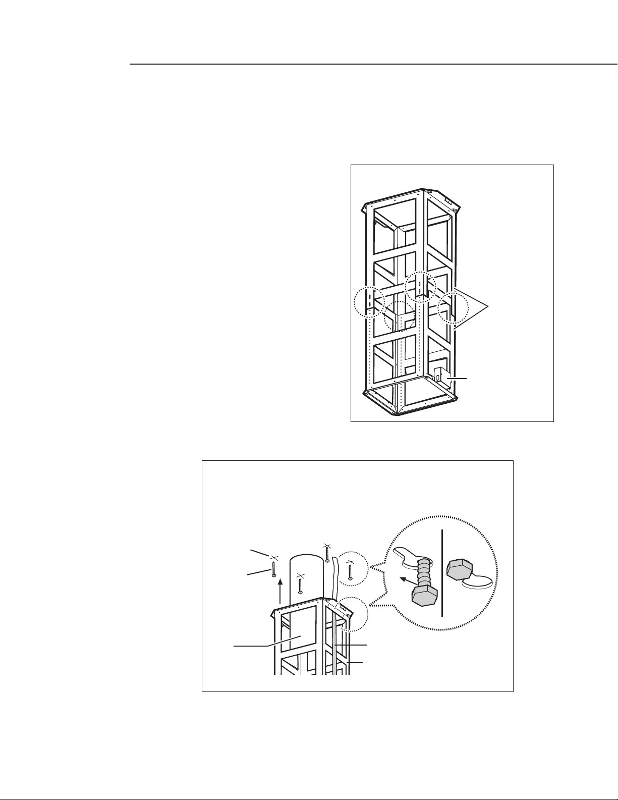
1. Adjust chimney mounting structure to E + 3/8” dimension as determined in installation height
calculation on page 7. Use 2 screws per attachment leg,see Fig.3.
2. To install Chimney Structure to ceiling, use a 10mm or adjustable wrench or flat head screwdriver.
a. Drill pilot holes into ceiling at fixing
points as determined in Step 6 under
Ceiling Preparation (Pg.8).
b. Screw the 4 lag screws provided (see
Fig. 4, do not tighten completely).
c. Attach mounting structure to joists with
the 4 lag screws provided.(see Fig.4,
keep 10” duct inside structure) .
AT T E NT I O N: Junction Box on the chimney
structure should be oriented to the right
side when facing the front of the cooktop.
d. Tighten the 4 lag screws, see Fig. 4.
FIG.3
FIG.4
Attachment
Leg
Fixing
point
Leg
screw
10" Duct
Junction
Box
Ceiling
1/2" Conduit
Chimney
Structure
Page 11

10
INSTALLATION
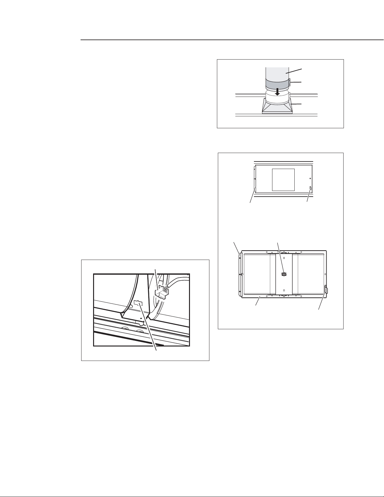
3. Assembly of the 10”Transition.
The transition supplied with the hood mounts to the top
of the hood, Figure 5.
a. Place the transition piece over the hood exhaust
and secure with 4 screws provided.
b. Duct tape connection between transition and
hood.
c. Remove tape holding damper.
4. Check that the screws on bottom of chimney structure
are partially screwed into place; these will serve to hang
and fix the canopy.
5. If already mounted in place remove all grease filters.
6. Back out the hanging screws on the bottom of the
chimney structure to 1/4” gap.
Lift the canopy up to the chimney support .
Carefully align the canopy keyhole to the screws on the
chimney support.
Slide the hood to engage the keyhole slots. See Fig. 6.
7. Tighten screws securely (from inside the canopy). Fix
canopy to structure with 4 screws from inside the
canopy.See Fig.7.
8. Make final angular adjustment to unit at ceiling if necessary, then finish installation adding two
fixing screws. See Fig. 8.
FIG.5
FIG.6
FIG.7
FIG.8
Duct
Transition
Top o
Hood
f
Screw
additional
fixing screw
Page 12
11
INSTALLATION
9. Ducting: There should be no more than 1"
gap between canopy transition and house
ducting. Adjust starting collar over both
ducts. Tighten collar. Fasten duct with
screws and tape per code. Screws must not
hamper the damper.See Fig.9.
INTEGRAL VENTILATOR INSTALLATION
(see Fig.10 to 11)
1. The Integral ventilator can be mounted to
discharge air towards the ceiling.So motor
connector may be located frontwards.
From the inside of the hood, slip motor into
the bracket on the left.
Rotate motor upwards until it snaps into the
spring clip on the right.
Secure the motor to the hood with the
machine screw and lock washer.
Plug connector into the motor, Fig. 11.
FIG. 10
FIG. 9
FIG. 11
10" Duct
Collar
Transition
From Control
Panel
Bracket
Fixing
point
Outlet
Bracket
Integral ventilator for 40" Hood
Motor Connector
Motor
support
Spring Clip
Spring Clip
Fixing
point
Motor connector
Page 13
INSTALLATION
12
2. Snap the central baffle filter panel into the place so the both rails engage with side pins on both
sides of hood.Drive 2 screws (1 on each side ) through baffle filter panel hole to hood.See Fig. 12.
3. Snap four-side baffle trim to hood (4 pins engage each side trim).The baffle trims are supplied
separately (for IVS52 only). See Fig. 13.
4. Install all baffle filters as per Use and Care Manual instructions.
Fig. 12
Fig. 13
Baffle filter panel
Baffle trim
Fixing screw location
Page 14
13
INSTALLATION
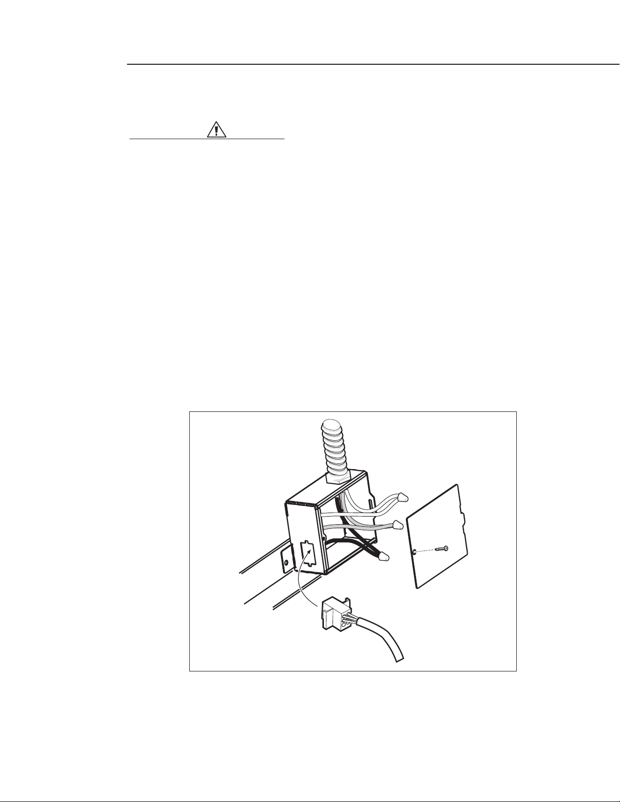
WIRING TO POWER SUPPLY
WAR NING:
Turn off power circuit at the service panel before wiring this unit.
120 VAC,15 Amp circuit required.
1. Remove j-box cover as shown in Fig. 14.
2. Remove the knockout and install the strain relief (conduit) connector (1/2") in junction box.
3. Run 3 wires; black,white and green (#14 AWG) in 1/2" conduit from service panel to junction box.
4. Connect black wire from service panel to black or red in junction box, white to white and green
to green-yellow.See Fig. 14.
5. Close junction box cover.
6. Plug cable at the top of the hood into the junction box connector.
7. Check all light bulbs to make sure they are secure in their sockets, then turn power on in service
panel and check lights and blower operation per Care & Use manual and install drip tray support
and filters.
FIG. 14
Junction
Box
1/2"
Conduit
From Control
Panel
Junction
Box
Cover
Page 15

14
INSTALLATION
FINAL ASSEMBLY
For final Chimney Cover installation, DO NOT USE ELECTRIC SCREW DRIVER.
NOTE: Overtightening screws can deform metal.
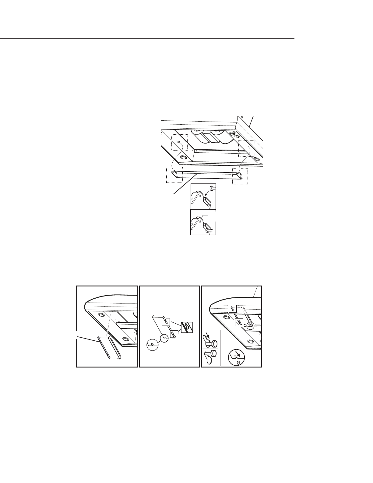
1. Install the cage nuts from inside the rectangular slots supplied with top and bottom duct covers.
See Fig.15.
A total of 14 nuts must be fitted.
FIG. 15
x
Duct cover
Top section
Duct cover
Top section
Duct cover
bottom section
Duct cover
Top section
Duct cover
bottom section
Page 16

15
INSTALLATION
2. Install the two brackets to the chimney structure supplied with the kit by using one screw each
side.
3. Join the two top sections of the duct cover.
Screw the two sections together with 8 screws (4 each side- see the top view in Fig.16 for
joining the two sections).
4. Install the top duct cover assembly to the bracket, near the ceiling, with two screws (one each
side).
FIG. 16
Fix to the top
Duct cover
Bracket
Duct cover
Top section
Top section
Top Duct
assembly
Diagram
Bracket
Drive a #10 x 2-1/4"
screw into wood
framing above
ceiling. This screw
supports the load of
the upper chimney
duct cover. One
screw each side.
Screw
Page 17

16
INSTALLATION
5. Join the two bottom sections of the duct cover which covers the chimney structure using 6
screws, (3 each side, see Fig. 17 for the plan diagram for joining the two sections).
6. Insert the bottom section of the duct cover in its seat so that it completely covers the chimney
structure.
7. Install the 4 supplied trims for duct cover channels to cover the fasteners of the bottom duct
covers. (CAUTION! THE BOTTOM FLUE TRIMS ARE THE NARROWER AND SHALLOWER ONES).
The wider and deeper trims are those used for the top flue,and must be cut to size.
If necessary, slightly expand the trims to ensure their adherence to the flue.
8. Turn the power on again at the electrical panel and check for correct hood operation.
9. Make sure to leave this
manual for the home owner.
FIG. 17
Screw
Duct cover
Front Bottom
section
Bottom Duct
assembly
Diagram
Duct cover
Rear Bottom
section
X
X
Tabs
Page 18

17
HOW TO OBTAIN SERVICE
BEFORE YOU CALL FOR SERVICE
Is the circuit breaker tripped or the fuse blown?
Is there a power outage in the area?
For warranty service, contact DCS Customer Care Representative at (888) 281-5698. Before you call,
please have the following information ready:
Model Number
Serial Number
Date of installation
A brief description of the problem
Your satisfaction is of the utmost importance to us. If a problem cannot be resolved to your satisfaction,
please call, write or email us at:
Write:
Fisher & Paykel Appliances,Inc.
Attention: DCS Customer Care
5900 Skylab Road
Huntington Beach, CA 92647
email: support@dcsappliances.com
Page 19

18
WARRANTY
LIMITED WARRANTY
When you purchase a new DCS Ventilation Product for personal or consumer use you automatically
receive a One year Limited Warranty covering parts and labor for the entire product, and a Five year
Limited Warranty on the switches and motor (parts only) for servicing within the 48 mainland United
States,Hawaii,Washington D.C and Canada.In Alaska the Limited Warranty is the same except that you
must pay to ship the Product to the service shop or for the service technician’s travel to your home.
Products for use in Canada must be purchased through the Canadian distribution channel to ensure
regulatory compliance.
If the Product is installed in a motor vehicle, boat or similar mobile facility,you receive the same One
year Limited Warranty, but you must bring the vehicle, boat or mobile facility containing the Product
to the service shop at your expense or pay the service technician’s travel to the location of the Product.
FISHER & PAYKEL UNDERTAKES TO:
Repair without cost to the owner either for material or labor any part of the Product,the serial number
of which appears on the Product, which is found to be defective. In Alaska, you must pay to ship the
Product to the service shop or for the service technician’s travel to your home.If the Product is installed
in a motor vehicle,boat or similar mobile facility,you must bring it to the service shop at your expense
or pay for the service technician’s travel to the location of the Product. If we are unable to repair a
defective part of the Product after a reasonable number of attempts,at our option we may replace the
part or the Product, or we may provide you a full refund of the purchase price of the Product (not
including installation or other charges).
This warranty extends to the original purchaser and any succeeding owner of the Product for products
purchased for ordinary single-family home use. All service under this Limited Warranty shall be
provided by Fisher & Paykel or its Authorized DCS Service Agent during normal business hours.
HOW LONG DOES THIS LIMITED WARRANTY LAST?
Our liability under this Limited Warranty for the entire product expires ONE YEAR from the date of
purchase of the Product by the first consumer. Our liability under this Limited Warranty for the
switches and motor (parts only) expires FIVE YEARS from the date of purchase of the Product by the
first consumer.
Our liability under any implied warranties, including the implied warranty of merchantability (an
unwritten warranty that the Product is fit for ordinary use) also expires ONE YEAR (or such longer
period as required by applicable law) from the date of purchase of the Product by the first consumer.
Some states do not allow limitations on how long an implied warranty lasts, so this limit on implied
warranties may not apply to you.
THIS WARRANTY DOES NOT COVER:
A. Service calls that are not related to any defect in the Product. The cost of a service call will be
charged if the problem is not found to be a defect of the Product.For example:
1. Correct faulty installation of the Product.
2. Instruct you how to use the Product.
3. Replace house fuses, reset circuit breakers, correct house wiring or plumbing, or replace light
bulbs.
4. Correct fault(s) caused by the user.
5. Change the set-up of the Product.
6. Unauthorized modifications of the Product.
Page 20

WARRANTY
19
7. Noise or vibration that is considered normal,for example,drain/fan sounds, regeneration noises
or user warning beeps.
8. Correcting damage caused by pests,for example, rats, cockroaches etc.
B. Defects caused by factors other than:
1. Normal domestic use or
2. Use in accordance with the Product’s User Guide.
C. Defects to the Product caused by accident,neglect, misuse, fire, flood or Act of God.
D. The cost of repairs carried out by non-authorized repairers or the cost of correcting such
unauthorized repairs.
E. Travel Fees and associated charges incurred when the product is installed in a location with limited
or restricted access. (i.e. airplane flights,ferry charges, isolated geographic areas).
F. Normal recommended maintenance as set forth in the Product’s User Guide.
If you have an installation problem contact your dealer or installer.You are responsible for providing
adequate electrical, exhausting and other connection facilities. We are not responsible for
consequential or incidental damages (the cost of repairing or replacing other property damaged if the
Product is defective or any of your expenses caused if the Product is defective). Some states do not
allow the exclusion or limitation of incidental or consequential damages, so the above limitation or
exclusion may not apply to you.
HOW TO GET SERVICE
Please read your User Guide. If you then have any questions about operating the Product, need the
name of your local DCS Authorized Service Agent,or believe the Product is defective and wish service
under this Limited Warranty,please contact your dealer or call us at:
TOLL FREE 1-888-281 5698 or contact us through our web site: www.dcsappliances.com.
You may be required to provide reasonable proof of the date of purchase of the Product before the
Product will be serviced under this Limited Warranty.
COMMERCIAL USE
This warranty applies to appliances used in residential applications; it does not cover their use in
commercial situations.
NO OTHER WARRANTIES
This Limited Warranty is the complete and exclusive agreement between you and Fisher & Paykel
regarding any defect in the Product. None of our employees (or our Authorized Service Agents) are
authorised to make any addition or modification to this Limited Warranty.
Warrantor: Fisher & Paykel Appliances, Inc.
If you need further help concerning this Limited Warranty,please call us at the above number, or write
to:
Fisher & Paykel Appliances, Inc.
5900 Skylab Road, Huntington Beach, CA 92647
This Limited Warranty gives you specific legal rights, and you may also have other rights which vary
from state to state.
Page 21

NOTES
20
Page 22

LA HOTTE À ÉVACUATION
PROFESSIONNELLE ISLAND
Guide d'installation
MODÈLES :
IVS40
IVS52
DS-364GL
RDS-364GD
Page 23

À L'INTENTION DE NOS CLIENTS
1
AV ER TI SSEMENT
Si les informations de ce manuel ne sont pas suivies à la lettre, un incendie ou
une explosion peuvent se produire et causer des dommages matériels, des
blessures ou la mort. Évitez de stocker ou d'utiliser de l'essence ou tout autre
liquide et vapeur inflammable à proximité de cet appareil électroménager ou
de tout autre.
AV ER TI SSEMENT
Pour réduire les risques de blessures en cas de feu de graisse sur la cuisinière,
respectez les consignes suivantes : Éteignez d'abord le brûleur. Étouffez les
flammes à l'aide d'un couvercle hermétique, d'une plaque à biscuits ou d'un
plateau métallique. Attention à ne pas vous brûler. Si les flammes ne
s'éteignent pas immédiatement, évacuez les lieux et appelez les pompiers. Ne
prenez jamais en main une poêle ou une casserole qui a pris feu - Vous pourriez
vous brûler. N'UTILISEZ PAS D'EAU, y compris des serviettes mouillées; une
explosion de vapeur violente pourrait en résulter. Utilisez un extincteur
SEULEMENT si :
1) Vous êtes sûr qu'il s'agit d'un extincteur de classe ABC et savez
comment le faire fonctionner.
2) L'incendie est limité et se limite à l'endroit où il s'est déclenché.
3) Vous êtes en train d'avertir les pompiers.
4) Vous pouvez combattre l'incendie le dos tourné vers une sortie.
Nous vous remercions d'avoir choisi cette îlot hotte à évacuation professionnelle Island de DCS.Nous avons conçu
ce Manuel d'utilisation et d'installation pour expliquer ses fonctions uniques. Il contient des informations
extrêmement utiles sur la façon de faire fonctionner et d'entretenir correctement votre nouvel appareil. Vous
pourrez ainsi en profiter pendant des années en toute sécurité.
Si vous avez des questions au sujet de notre produit,communiquez avec un représentant du centre de service à la
clientèle DCS par téléphone : 1-888-281-5698,par courriel : support@dcsappliances.com,ou par courrier :
AUTORISÉ POUR APPAREILS ÉLECTROMÉNAGERS RÉSIDENTIELS ET POUR USAGE
RÉSIDENTIEL SEULEMENT.
VEUILLEZ LIRE TOUTES LES INSTRUCTIONS AVANT DE COMMENCER.
L'installation doit être conforme aux codes en vigueur.
Fisher & Paykel Appliances, Inc.
Attention: DCS Customer Care
5900 Skylab Road
Huntington Beach, CA 92647
www.dcsappliance.com
Page 24

À L'INTENTION DE NOS CLIENTS
2
CONSIGNES DE SÉCURITÉ ......................................................................................................................................3-4
PIÈCES ........................................................................................................................................................................................5
AVANT D'INSTALLER LA HOTTE.........................................................................................................................6-8
INSTALLATION...............................................................................................................................................................9-16
POUR L'OBTENTION DE SERVICE.......................................................................................................................17
GARANTIE.......................................................................................................................................................................18-20
VEUILLEZ CONSERVER CE MANUEL À TITRE DE RÉFÉRENCE.
TABLE DES MATIÈRES
AV ER TI SSEMENT RELATIF À LA SÉCURITÉ :
Coupez le circuit électrique au niveau du panneau de service et verrouillez le
panneau avant de brancher cet appareil électroménager.
Alimentation : Circuit de branchement de 120 V c.a.,60 Hz, 15 A.
POUR VOTRE SÉCURITÉ
Si vous sentez une odeur de gaz :
N'essayez pas d'allumer aucun appareil électroménager.
Ne touchez aucun interrupteur électrique; n'utilisez aucun téléphone dans
l'édifice.
Appelez immédiatement votre fournisseur de gaz de chez un voisin. Suivez
les instructions du fournisseur de gaz.
Si vous n'arrivez pas à joindre votre fournisseur de gaz, appelez les
pompiers.
Toute installation ou service doit être confié à un installateur qualifié, un
organisme de service ou le fournisseur de gaz.
Page 25

MESURES DE SÉCURITÉ ET DE PRÉCAUTION
3
MISE EN GARDE :
Pour ventilation générale seulement.N'utilisez pas l'appareil pour évacuer des
substances ou vapeurs dangereuses ou explosives.
AV ERTISSEMENT :
Pour réduire les risques de feu de graisse sur la cuisinière :
A) Ne laissez jamais les plaques de cuisson sur réglage élevé sans surveillance. L'ébullition peut
provoquer des débordements graisseux pleins de fumée pouvant prendre feu. Chauffez l'huile
lentement, à feu doux ou moyen.
B) Allumez toujours la hotte lorsque vous cuisinez à feu vif ou que vous flambez des aliments.
C) Nettoyez les ventilateurs fréquemment. Ne laissez pas s'accumuler la graisse sur le ventilateur
ou le filtre.
D) Utilisez des récipients de taille appropriée. Utilisez toujours des ustensiles de cuisson dont la
taille est appropriée à la surface de votre élément de cuisson.
Il peut s'avérer nécessaire d'assurer de l'air d'appoint pour empêcher l'air de s'écouler dans une
cheminée, une porte ou fenêtre non hermétique, ou l'ouverture d'un foyer.
AV ERTISSEMENT :
Pour réduire les risques d'incendie,de choc électrique et de blessures,respectez
les consignes suivantes :
A) Utilisez l'appareil strictement selon les consignes du fabricant et communiquez avec celui-ci si
vous avez des questions.
B) Avant tout entretien ou nettoyage, coupez le courant au niveau du panneau de service et
verrouillez le dispositif de sectionnement pour éviter une mise sous tension accidentelle.S'il ne
peut être verrouillé, fixez solidement un avertissement clairement visible (une étiquette, p. ex.)
au panneau de service.
C) L'installation et le câblage électrique doivent être effectués conformément aux codes et
normes en vigueur,y compris les constructions classées résistant au feu.
D) Pour éviter le refoulement d'air, une quantité d'air suffisante est nécessaire pour assurer une
bonne combustion et l'évacuation des gaz à travers le carneau (cheminée) de l'appareil à gaz.
Suivez les consignes du fabricant de l'appareil de cuisson ainsi que les normes de sécurité
comme celles publiées par la National Fire Protection Association (NFPA) et la American Society
for Heating, Refrigeration and Air Conditioning Engineers (ASHRAE), ainsi que les normes
locales.
E) Faites preuve de prudence lorsque vous découpez ou percez des murs ou des plafonds afin de
ne pas endommager le câblage électrique et autres installations des services publics pouvant
être dissimulées.
AV ERTISSEMENT :
Pour réduire les risques d'incendie et pour assurer une bonne évacuation de
l'air, veillez à ce que l'air soit acheminé vers l'extérieur. Ne rejetez pas l'air
évacué dans les espaces entre les murs ou les plafonds,ni dans les greniers, les
galeries ou les garages.
Page 26

MESURES DE SÉCURITÉ ET DE PRÉCAUTION
4
REMARQUE : L'appareil DOIT évacuer l'air vers l'extérieur du bâtiment.
IMPORTANT : Reportez-vous aux informations sur les conduits indiquées dans ce manuel.
AV ERTISSEMENT :
Pour réduire les risques de choc électrique ou de blessures, les hottes à
évacuation doivent être installées avec des ventilateurs dont l'utilisation avec
ces hottes a été approuvée.
AV ERTISSEMENT :
Pour réduire les risques d'incendie, utilisez des conduits métalliques
uniquement.
Installez cette hotte conformément à toutes les exigences spécifiées.
AV ERTISSEMENT :
Afin de réduire les risques d'incendie ou de choc électrique, évitez d'utiliser
cette hotte avec un appareil externe de contrôle de vitesse transistorisé.
AV ERTISSEMENT :
Pour réduire les risques de blessures en cas de feu de graisse sur la cuisinière,
respectez les consignes suivantes : Éteignez d'abord le brûleur. Étouffez les
flammes à l'aide d'un couvercle hermétique, d'une plaque à biscuits ou d'un
plateau métallique. Attention à ne pas vous brûler. Si les flammes ne
s'éteignent pas immédiatement, évacuez les lieux et appelez les pompiers. Ne
prenez jamais en main une poêle ou une casserole qui a pris feu - Vous
pourriez vous brûler.N'UTILISEZ PAS D'EAU,y compris des serviettes mouillées;
une explosion de vapeur violente pourrait en résulter. Utilisez un extincteur
SEULEMENT si :
1) Vous êtes sûr qu'il s'agit d'un extincteur de classe ABC et savez
comment le faire fonctionner.
2) L'incendie est limité et se limite à l'endroit où il s'est déclenché.
3) Vous êtes en train d'avertir les pompiers.
4) Vous pouvez combattre l'incendie le dos tourné vers une sortie
AV ERTISSEMENT :
Pour réduire les risques d'incendie, de choc électrique ou de blessures
corporelles, le Island Hood (IVS40/52) doit être installé avec la structure de
cheminée (IVCK) fournie dans la boîte séparée.Il n'y a pas de substitut pour les
pièces sur commande.
.
Page 27

5
PIÈCES
PIÈCES INCLUSES AVEC LA HOTTE
Toit d'évacuation de la hotte avec ampoules installées.
Tr ansition métallique avec registres antirefoulement
Instructions d'utilisation et entretien,et d'installation
Filtres (quantité en fonction du modèle et des dimensions)
Vis
Ventilateurs intégraux
4 baffle le taille
Baffle le filtre panneau
PIÈCES NON INCLUSES AVEC LA HOTTE
Ruban pour conduits
Tu be 1/2 po
Serres-fils
Structure de cheminée de la hotte et couvre-conduits. Ces articles sont compris avec le kit
d'accessoires modèle IVCK, lequel doit être commandé séparément.
Page 28

6
AVANT D'INSTALLER LA HOTTE
1. Pour assurer une évacuation d'air optimale, installez un conduit droit ou comprenant le moins de
coudes possibles.
MISE EN GARDE :
Dirigez l'évacuation d'air vers l'extérieur du bâtiment seulement.
2. Il faut deux personnes pour l'installation.
3. La hotte est munie de vis adéquats pour la plupart des surfaces. Consultez un installateur qualifié.
Vérifiez s'ils conviennent parfaitement à votre plafond.
4. N'utilisez pas de conduits flexibles.
5. CLIMAT FROID : L'installation doit disposer d'un registre antirefoulement supplémentaire pour
minimiser le reflux d'air froid et d'un isolant thermique non métallique pour réduire la conduction
des températures extérieures à travers le conduit. Le registre doit être installé du côté air froid
(paroi extérieure) de l'isolant thermique.
Placez l'isolant à un endroit aussi proche que possible du point d'entrée du conduit dans la partie
chauffée de la maison.
6. Il appartient à l'utilisateur de décider de la hauteur d'installation de la hotte au-dessus de la table
de cuisson ou de la cuisinière. Une hauteur d'installation plus basse contribue à améliorer l'efficacité avec laquelle les odeurs de cuisson, la graisse et la fumée sont capturées. Ces hottes sont
homologuées pour être installées à 76,2 cm (30 po) au-dessus des tables de cuisson et des
cuisinières. Les personnes de grande taille trouveront peut-être qu'une telle hauteur n'est pas
pratique. DCS recommande une hauteur d'installation entre 76,2 et 91,4 cm (30 et 36 po).
7. La hotte à évacuation modèle IVS52 est recommandée pour une installation au-dessus des
cuisinières et tables de cuisson DCS modèles RGS-364GL ou CS-364GL.
8. Air d'appoint : Il se peut que les codes du bâtiment en vigueur exigent l'utilisation d'un système
d'air d'appoint si vous utilisez un système de ventilation à conduit dont le volume est supérieur au
volume de déplacement d'air spécifié.
Le volume spécifié varie d'un endroit à l'autre. Consultez votre spécialiste en chauffage, ventilation
et climatisation en ce qui concerne les exigences particulières à votre région.
Page 29

7
AVANT D'INSTALLER LA HOTTE
INSTALLATION TYPIQUE
La figure 1 ci-dessous illustre une installation de hotte typique. Lorsqu'elle est installée avec le kit
d'accessoires de cheminée IVCK, la hotte peut être installée à une hauteur de 76,2 à 91,4 cm (30 à 36
po) dans les cuisines dont le plafond s'élève de 2,6 à 3 m (8 à 10 pieds).Toute installation en dehors
de cette norme nécessite un cadrage sur mesure. Consultez un installateur qualifié pour un cadrage
sur mesure.
CONDUITS
Procurez-vous un conduit rond de 25,4 cm (10 po). La longueur totale des conduits ne peut pas
dépasser 12,2 m (40 pieds), y compris les coudes et les transitions.
CARACTÉRISTIQUES ÉLECTRIQUES
Installez un tube de 1,3 cm (1/2 po), à partir du panneau de service, suffisamment long pour atteindre la hotte une fois installé.
Assurez une alimentation de 120 V 60 Hz,15 A (minimum).
CALCUL DE LA HAUTEUR D'INSTALLATION
Voir la figure 1.
a) Sélectionnez une hauteur d'installation de hotte C qui convient à l'utilisateur. (76,2 à 91,4 cm
[30 à 36 po] recommandé, 30 po minimum).
b) Calculez la hauteur de couvercle de cheminée E en utilisant la formule ci-dessous.
Conservez ce calcul pour référence ultérieure durant
l'installation.
A = Hauteur du plafond de la cuisine
B= Hauteur du comptoir (91,4cm/36 po standard)
C= Hauteur d'installation de la hotte.
D= Hauteur du toit d'évacuation = 33 cm (13 po)
E= Hauteur du couvercle de cheminée = A – B – C – D
REMARQUE : La hauteur du couvercle de
cheminée peut être ajustée de 62,2 à
91,4 cm (24-1/2 à 36 po) en fonction
de la hauteur d'installation de hotte
voulue.
FIG.1
E
D
A
C
B
Page 30

8
AVANT D'INSTALLER LA HOTTE
PRÉPARATION DU PLAFOND
Installation des supports au-dessus de la cloison sèche du plafond.
REMARQUE : Tenez compte de la profondeur de la hotte; certains modèles sont beaucoup plus
profonds que la table de cuisson.
REMARQUE : Les étapes suivantes s'appliquent à l'installation de la hotte en utilisant le type de
structure de cheminée/couvre-conduit modèle IVCK.D'autres types d'installation peuvent nécessiter un cadrage sur mesure, etc.Consultez un installateur qualifié.
1. Marquez les lignes médianes de la table de cuisson ou de la
cuisinière sur le plafond au-dessus.Servez-vous des lignes médianes
marquées au plafond pour positionner le gabarit de montage. La
flèche avant sur le gabarit doit pointer vers l'avant de la surface de
cuisson. Marquez les trous de montage indiqués sur le gabarit.
2. Retirez et conservez le gabarit.Découpez et retirez la cloison sèche
du plafond. Installez des pièces de bois 2 x 4 po d'une longueur
suffisante entre les poutrelles afin de disposer de points de
montage pour la cheminée, tel qu'illustré à la figure 2. Utilisez le
gabarit pour les dimensions et le dégagement requis.
Prenez soin de bien fixer les pièces de bois en vous assurant qu'elles
soient de niveau. Consultez un professionnel si vous éprouvez des
difficultés ou si votre installation présente certaines particularités.
Consultez le gabarit et la figure 2.
IMPORTANT :
La structure du plafond (les poutrelles et les pièces de
bois) doit être capable de supporter le poids de la
hotte (environ 50 kg/110 lb pour une hotte de 1 m/40
po et 65 kg/143 lb pour une hotte 1,3 m/52 po) ainsi
que toute charge involontaire exercée par l'utilisateur.
3. INSTALLATION DES CONDUITS
Pour IVS-52 : Installez un conduit d'évacuation de 25,4 cm/10 po
sur une longueur de E moins 11,7 cm/4-5/8 po (E – 11,7 cm/4-5/8
po) à partir du plafond.
Voir fig.1. Évitez d'utiliser un conduit plus petit que celui spécifié.
4. Installez un tube électrique de 1,3 cm/1/2 po à l'emplacement
marqué sur le gabarit, sur une longueur de E moins 7,9 cm/3-1/8
po (E – 7,9 cm/3-1/8 po) à partir du plafond (utilisez la formule de
la figure 1).
5. Installez la cloison sèche autour du conduit et du tube; puis finissez
le plafond.
6. Collez le gabarit en place en vous servant des lignes médianes
marquées à l'étape 1. Marquez les emplacement des points de
montage. Retirez le gabarit.
FIG.2
Page 31

9
INSTALLATION
INSTALLATION DE LA HOTTE
1. Réglez la structure de montage de la cheminée à la dimension E + 0,95 cm/3/8 po selon le calcul
de hauteur d'installation effectué à la page 7. Utilisez 2 vis par pied de fixation; voir figure 3.
2. Pour installer la structure de cheminée au plafond,utilisez une clé de 10 mm, une clé à molette ou
un tournevis à tête plate.
a. Percez des trous de guidage dans le
plafond, aux points de fixation
déterminés à l'étape 6 sous la section
Préparation du plafond (p.8).
b. Vissez les 4 tire-fonds fournis (voir figure
4; ne serrez pas complètement).
c. Fixez la structure de montage aux
poutrelles à l'aide des 4 tire-fonds
fournis. (Voir figure 4, gardez le conduit
de 10 po à l'intérieur de la structure.)
AT T E NT I O N : La boîte de jonction sur la
structure de cheminée doit être orientée
vers le côté droit par rapport à l'avant de
la table de cuisson.
d. Serrez les 4 tire-fonds; voir figure 4.
FIG.3
FIG.4
Pied de
fixation
Boîte de
jonction
Point
de
fixation
Vis de
pied
Conduit 25,4 cm (10 po)
Plafond
Tube 1,3 cm (1/2 po)
Structure de
cheminée
Page 32

10
INSTALLATION
3. Assemblage de la transition de 25,4 cm/10 po.
La transition fournie avec la hotte doit être installée en
haut de la hotte (figure 5).
a. Placez la transition sur l'évacuation de la hotte et
fixez-la à l'aide des 4 vis fournies.
b. Recouvrez de ruban pour conduits la connexion
située entre la transition et la hotte.
c. Enlevez le ruban retenant le registre.
4. Vérifiez que les vis sur la partie inférieure de la structure
de cheminée sont partiellement vissées; celles-ci
serviront à accrocher et fixer le toit d'évacuation.
5. Si les filtres à graisses sont déjà installés, enlevez-les.
6. Dévissez les vis suspendues sur la partie inférieure de la
structure de cheminée de façon à laisser un espace de
0,6 cm (1/4 po).
Soulevez le toit d'évacuation vers le support de la
cheminée.
Alignez soigneusement le trou de serrure du toit
d'évacuation sur le support de cheminée.
Glissez la hotte de façon à accrocher les trous de serrure.
Voir fig.6.
7. Serrez bien les vis (de l'intérieur du toit d'évacuation). Fixez le toit d'évacuation à la structure à
l'aide de 4 vis, de l'intérieur du toit d'évacuation. Voir fig. 7.
8. Ajustez les angles de l'appareil sur le plafond au besoin, puis terminez l'installation en ajoutant
deux vis de fixation.Voir fig.8.
FIG.5
FIG.6
FIG.7
FIG.8
Transition
de conduit
Dessus de
la hotte
Vis
Vis de fixation
supplémentaire
Page 33

11
INSTALLATION
9. Conduits : Il ne doit pas y avoir plus d'un pouce
entre la transition du toit d'évacuation et les
conduits de la maison. Ajustez le collier de
connexion sur les deux conduits. Serrez le collier.
Fixez le conduit à l'aide de vis et de ruban confor
mément au code en vigueur.Les vis ne doivent
pas gêner le registre.Voir fig.9.
INSTALLATION DU VENTILATEUR INTÉGRAL
(Voir fig. 10 à 11)
1. Le ventilateur intégral peut être monté de
façon à évacuer l'air vers le plafond.Le
connecteur moteur peut être vers localisé
l'avant.
De l'intérieur de la hotte, glissez le moteur
dans le support à gauche.
Tournez le moteur vers le haut jusqu'à ce
qu'il se mette en place d'un déclic dans
l'attache-ressort à droite.
Fixez le moteur à la hotte à l'aide de la vis à
métaux et de la rondelle de blocage.
Branchez le connecteur dans le moteur,
fig. 11.
FIG. 10
FIG. 9
FIG. 11
Conduit 25,4 cm
(10 po)
Collier
Pièce de
transition
À partir du panneau
de contrôle
Support
Point de
fixation
Sortie
Support
Ventilateur intégral pour hotte de 40 po
Connecteur du moteur
Support du
moteur
Attache-ressort
Attache-ressort
Point de
fixation
Connecteur du
moteur
Page 34

12
INSTALLATION
2. Enfoncez d'un déclic le panneau du filtre en chicanes central de sorte que les deux rails
s'emboîtent dans les tiges latérales des deux côtés de la hotte.Insérez 2 vis (1 de chaque côté ) à
travers le trou du panneau du filtre en chicanes et dams la hotte.Voir fig. 12.
3. Enfoncez d'un déclic la garniture de chicane (fournie séparément) à quatre côtés sur la hotte
(4 tiges s'enfoncent dans chaque côté de la garniture) (IVS-52 seulement). Voir fig. 13.
4. Installez tous les filtres en chicanes conformément aux instructions du manuel d'utilisation et
d'entretien.
FIG. 12
FIG. 13
Emplacement de la vis de fixation
Page 35

13
INSTALLATION
CÂBLAGE D'ALIMENTATION
AV ERTISSEMENT :
Coupez le circuit électrique au niveau du panneau de service avant de
brancher cet appareil.
Circuit de 120 V c.a.,5 A requis
1. Retirez la boîte de jonction tel qu'indiqué à la fig.14.
2. Enlevez le trou d'évacuation et installez le raccord de retenue (tube;1,3 cm [1/2 po]) dans la boîte
de jonction.
3. Faites passer trois fils, noir, blanc et vert (14 AWG), dans un tube de 1,3 cm (1/2 po),du panneau
de service à la boîte de jonction.
4. Connectez le fil noir du panneau de service au fil noir ou rouge de la boîte de jonction, le blanc
au blanc et le vert au vert-jaune. Voir fig. 14.
5. Fermez le couvercle de la boîte de jonction.
6. Branchez le câble de la partie supérieure de la hotte au connecteur de la boîte de jonction.
7. Vérifiez toutes les ampoules pour vous assurer qu'elles sont bien vissées dans leurs douilles,
mettez ensuite le courant au niveau du panneau de service et vérifiez les lumières et le
fonctionnement du ventilateur conformément au manuel d'utilisation et d'entretien, puis
installez le support du récipient à graisse et les filtres.
FIG. 14
Tub e 1,3 cm
(1/2 po)
Boîte de
jonction
Couvercle
de la boîte
de jonction
À partir du
panneau de
contrôle
Page 36

14
INSTALLATION
ASSEMBLAGE FINAL
N'UTILISEZ PAS DE TOURNEVIS ÉLECTRIQUE pour l'installation finale du couvercle de cheminée.
REMARQUE : Si les vis sont trop serrées,cela peut déformer le métal.
1. Installez les écrous de cage de dans les emplacements rectangulaires fournis avec les
couvre-conduits supérieur et inférieur. Voir fig. 15.
Il faut installer 14 écrous au total.
FIG. 15
x
Section
supérieure du
couvre-conduit
Section
supérieure du
couvre-conduit
Section
inférieure du
couvre-conduit
Section
supérieure du
couvre-conduit
Section inférieure
du couvre-conduit
Page 37

15
INSTALLATION
2. IInstallez les deux supports sur la structure de cheminée fournie avec le kit en utilisant une vis de
chaque côté.
3. Joignez les deux sections supérieures du couvre-conduit.
Vissez les deux sections ensemble au moyen de 8 vis (4 de chaque côté; voir la vue de dessus à
la figure 16 montrant comment joindre les deux sections).
4. Fixez le haut du couvre-conduit au support,près du plafond, à l'aide de deux vis (une de chaque
côté).
FIG. 16
Fixer sur le haut
Section
supérieure du
couvre-
Support
Section
supérieure du
couvre-conduit
conduit
Schéma
du conduit
supérieur
Support
Enfoncez une vis nº
10 x 2-1/4 po dans la
charpente en bois
au-dessus du
plafond. Cette visse
supporte la charge
du couvre-conduit
supérieur de la
cheminée.
Une vis de chaque
côté.
Vis
Page 38

16
INSTALLATION
5. Joignez les deux sections inférieures du couvre-conduit qui recouvre la structure de cheminée à
l'aide de 6 vis,(trois de chaque côté; voir le schéma de la figure 17 montrant comment joindre les
deux sections).
6. Insérez la section inférieure du couvre-conduit dans son siège de sorte qu'elle couvre
complètement la structure de cheminée.
7. Installez les quatre garnitures fournies pour les canaux du couvre-conduit afin de recouvrir les
fixations des couvre-conduits inférieurs. (MISE EN GARDE! LES GARNITURES DE CARNEAU
INFÉRIEURES SONT PLUS ÉTROITES ET MOINS PROFONDES.)
Les garnitures les plus larges et les plus profondes sont utilisées pour le carneau supérieur et
doivent être découpées selon ses dimensions.
Élargissez légèrement les
garnitures au besoin afin
d'assurer leur adhérence au
carneau.
8. Rétablissez le courant au niveau
du panneau électrique et vérifiez
que la hotte fonctionne
correctement.
9. Prenez soin de laisser ce manuel
au propriétaire de la résidence.
FIG. 17
Section inférieure
avant du couvreconduit
Schéma du
conduit
inférieur
X
Vis
Section inférieure
arrière du couvreconduit
X
Languettes
Page 39

17
POUR L'OBTENTION DE SERVICE
AVANT D'APPELER LE SERVICE TECHNIQUE
Est-ce que le disjoncteur s'est déclenché ou que le fusible est grillé?
Y a-t-il une coupure de courant dans le secteur?
Pour le service sous garantie, contactez le représentant du centre de service à la clientèle DCS au
(888) 281-5698. Avant d'appeler,veuillez avoir les informations suivantes à portée de main :
Numéro de modèle
Numéro de série
Date d'installation
Brève description du problème
Preuve d'achat
Votre satisfaction revêt la plus grande importance pour nous. Si un problème n'est pas résolu à votre
entière satisfaction, veuillez communiquer avec nous par téléphone, courrier ou courriel :
Écrivez-nous à l'adresse suivante :
Fisher & Paykel Appliances,Inc.
Attention: DCS Customer Care
5900 Skylab Road
Huntington Beach, CA 92647
Courriel : support@dcsappliances.com
Page 40

18
GARANTIE
GARANTIE LIMITÉE
Lors de l'achat d'un appareil de ventilation neuf DCS pour usage personnel ou non commercial, vous
bénéficiez automatiquement d'une garantie limitée d'un an couvrant les pièces et la main d'œuvre
pour l'intégralité du produit, et d'une garantie limitée de cinq ans sur les interrupteurs et le moteur
(pièces seulement) valide dans les 48 états continentaux des États-Unis, ainsi que Hawaï, Washington
D.C. et le Canada. La garantie limitée est la même en Alaska sauf que vous devez payer les frais
d'expédition du produit à un centre de service ou les frais de déplacement d'un technicien dans le cas
d'une visite à domicile. Les produits destinés à une utilisation au Canada doivent être achetés auprès
d'un distributeur canadien afin de respecter la réglementation en vigueur.
Si le produit est installé dans un véhicule ou bateau à moteur, ou une installation mobile similaire, vous
bénéficiez de la même garantie limitée d'un an, mais vous devrez acheminer à vos frais ledit véhicule,
bateau ou installation mobile contenant le produit jusqu'au centre de service ou payer les frais de
déplacement du technicien jusqu'à l'emplacement où se trouve le produit.
FISHER & PAYKEL S'ENGAGE À :
entreprendre à ses frais (pièces et main-d'oeuvre) toutes réparations du produit (sur lequel figure le
numéro de série) jugé défectueux. En Alaska, vous devez payer les frais d'expédition du produit à un
centre de service ou les frais de déplacement d'un technicien dans le cas d'une visite à domicile. Si le
produit est installé dans un véhicule ou bateau à moteur, ou une installation mobile similaire, vous
devez l'acheminer à vos frais jusqu'au centre de service ou payer les frais de déplacement du
technicien jusqu'à l'emplacement où se trouve le produit.Si nous sommes dans l'incapacité de réparer
une pièce défectueuse du produit après un nombre raisonnable de tentatives,nous pourrons, à notre
choix, remplacer la pièce ou le produit, ou vous rembourser entièrement le prix d'achat du produit (à
l'exclusion des frais d'installation ou autres frais.)
Cette garantie s'applique à l'acheteur initial et à tous les propriétaires successifs du produit dans la
mesure où il s'agit d'un produit acheté pour une utilisation à domicile normale. Tout service couvert
par cette garantie limitée sera assuré par Fisher & Paykel ou son agent de service DCS agréé durant les
heures d'ouverture normales.
QUELLE EST DURÉE DE CETTE GARANTIE LIMITÉE?
Notre responsabilité en vertu de cette garantie limitée concernant l'intégralité du produit expire UN
AN à partir de la table d'achat du produit par le premier acheteur. Notre responsabilité en vertu de
cette garantie limitée concernant les interrupteurs et le moteur (pièces seulement) expire CINQ ANS à
partir de la date d'achat du produit par le premier acheteur.
Notre responsabilité en vertu de toute garantie implicite, y compris la garantie implicite de qualité
marchande (la garantie tacite selon laque le produit est approprié pour un usage normal) expire
également UN AN (ou une période plus longue si requis par la loi) à partir de la date d'achat du produit
par le premier acheteur.Certaines juridictions ne permettent pas la limitation de la garantie implicite,
il est donc possible que la limitation ci-dessus sur les garanties implicites ne s'applique pas à vous.
NE SONT PAS COUVERTS PAR LA GARANTIE :
A. Les appels de service n'ayant aucun rapport avec un défaut éventuel du produit. Le coût de l'appel
de service sera facturé s'il se trouve que le problème n'est pas dû à un défaut du produit. Par
exemple :
1. Corriger une mauvaise installation du produit.
2. Montrer comment utiliser le produit.
Page 41

19
GARANTIE
3. Remplacer des fusibles du domicile, réarmer les disjoncteurs, réparer les fils électriques ou la
plomberie du domicile, ou remplacer des ampoules.
4. Corriger des anomalies causées par l'utilisateur.
5. Changer la configuration du produit.
6. Modifications non autorisées du produit.
7. Bruits ou vibrations considérés comme normaux, par exemple les bruits de drain ou de
ventilateur,les bruits de régénération (vibrations, sifflements) ou les signaux d'avertissement à
l'intention de l'utilisateur.
8. Corriger des dommages causés par des animaux nuisibles, par exemple des rats, des
coquerelles, etc.
B. Défauts causés par des facteurs autres que :
1. Utilisation domestique normale ou
2. Utilisation conformément aux indications du guide de l'utilisateur.
C. Défauts du produit pour cause d'accident, négligence,mauvaise utilisation, incendie, inondation ou
calamité naturelle.
D. Les coûts des réparations effectuées par des techniciens non autorisés ou le coût de correction de
ces réparations non autorisées.
E. Les frais de voyage et les frais connexes encourus lorsque le produit est installé dans un lieu à accès
illimité ou restreint (déplacement par avion ou par bateau,régions géographiques isolées, etc.).
F. Entretien normal recommandé par le guide l'utilisateur.
Contactez votre distributeur ou votre installateur en cas de problème d'installation. Il vous incombe
d'assurer une installation électrique, une ventilation et toute autre connexion appropriées. Nous ne
sommes pas responsables des dommages indirects ou accessoires (coût de réparation ou de
remplacement d'autres biens endommagés parce que le produit était défectueux ou tout autre coût
que vous auriez encouru parce que le produit était défectueux). Certaines juridictions interdisent
l’exclusion ou la restriction de la responsabilité des dommages indirects ou accessoires; l’exclusion ou
la restriction indiquée ci-dessus peut donc ne pas s'appliquer à votre cas particulier.
POUR OBTENIR DES RÉPARATIONS
Veuillez consulter le guide de l'utilisateur. Si vous avez des questions concernant l'utilisation du
produit, que vous cherchez le nom de l'agent de service DCS agréé local ou que pensez que le produit
est défectueux et désirez le faire réparer dans le cadre de cette garantie limitée,veuillez contacter votre
distributeur ou nous appeler au numéro suivant :
(NUMÉRO SANS FRAIS) 1-888-281 5698 ou contactez-nous par l'intermédiaire de notre site
Web : www.dcsappliances.com.
Vous devrez peut-être présenter une preuve raisonnable de la date d'achat du produit avant de
pouvoir bénéficier d'une réparation dans le cadre de cette garantie limitée.
UTILISATION COMMERCIALE
Cette garantie s'applique à des appareils électroménagers utilisés à domicile;elle ne couvre pas les cas
d'utilisation commerciale.
Page 42

20
GARANTIE
AUCUNE AUTRE GARANTIE
Cette garantie limitée constitue l'accord entier et exclusif entre vous et Fisher & Paykel en ce qui
concerne tout défaut du produit.Aucun de nos employés (ou agents de service agréés) n'est autorisé
à apporter des ajouts ou des modifications à cette garantie limitée.
Garant : Fisher & Paykel Appliances, Inc.
Si vous avez besoin d'aide au sujet de cette garantie illimitée, veuillez nous appeler au numéro cidessus ou nous écrire à l'adresse suivante :
Fisher & Paykel Appliances, Inc.
5900 Skylab Road, Huntington Beach, CA 92647
États-Unis
Cette garantie limitée vous donne des droits juridiques spécifiques et vous pouvez bénéficier d'autres
droits qui varient d'une juridiction à l'autre.
Page 43

NOTES
21
Page 44

NOTES
22
Page 45

NOTES
23
Page 46

Fisher & Paykel Appliances,Inc.
5900 Skylab Road, Huntington Beach, CA 92647
Customer Care: 888.281.5698
Fax:714.372.7003
www.dcsappliances.com
As product improvement is an ongoing process at DCS, we
reserve the right to change specifications or design without
notice.
DCS améliore constamment ses produits et se réserve le droit
de modifier les spécifications ou la conception de ses produits
sans aucun préavis.
P/N 17804 Rev.D
Litho in USA 02/2005
 Loading...