

Page 1

GRIDDLE
GDE1-0 Models
INSTALLATION GUIDE
US CA
Page 2

!
DANGER
SAFETY AND WARNINGS
!
WARNING!
Electric Shock Hazard
Failure to follow this advice may result in
electric shock or death.
• This appliance is equipped with a three-prong or
four-prong grounding plug for your protection
against shock hazard and should be plugged
directly into a properly grounded power outlet.
IF YOU SMELL GAS
• Shut off gas to the appliance.
• Extinguish any open flame.
• Open lid.
• If odor continues, keep away from the
appliance and immediately call your
gas supplier or your fire department.
!
WARNING
• Do not store or use gasoline or other
flammable liquids or vapors in the
vicinity of this or any other appliance.
• An LP cylinder not connected for use
must not be stored in the vicinity of
this or any other appliance.
• Never remove the grounding plug or use with
a 2 prong adapter.
• Use only extension cords with a 3 prong grounding
plug, rated for the power of the equipment, and
approved for outdoor use with a W-A marking.
• Do not immerse cord or plugs in water or other
liquid.
!
WARNING!
Fire Hazard
Failure to follow this advice may result in a fire
causing death or serious injury.
• This unit is for outdoor use only. Do not operate
the side burner/griddle under un protected
combustible construction. Do not use in buildings,
garages, sheds, breezeways, covered structures or
other such enclosed areas.
• Never store a spare LP cylinder under or near this
unit. Do not fill the gas tank more than 80% of its
total capacity
.
• Do not use aluminium foil to line drip pans. This
can interfere with combustion, air flow or trap
excessive heat in the control area. The result of
this can be melted dials or damaged ignition
components.
2
Page 3
SAFETY AND WARNINGS
!
WARNING!
Hot Surface Hazard
Failure to follow this advice may result in fire,
burns, scalds or personal injury.
• Accessible parts may become hot during use.
• When in use, do not touch the burner, grate,
or immediate surrounding area as these areas
become extremely hot. Clean the with caution.
• Never let clothing or other flammable materials
come in contact with or get too close to any
grate, burner or hot surface until it has cooled.
• Never lean over an open unit. When lighting a
burner, always pay close attention to what you are
doing. Be certain you are pushing the burner dial
when you attempt to light.
• Never operate the unit without a drip tray. Let hot
grease cool before attempting to handle it. Avoid
letting grease deposits collect in the drip pan.
• Ensure all controls are turned off and the unit
is cool before using any type of aerosol cleaner
on or around the product. The chemical that
produces the spraying action could, in the
presence of heat, ignite or cause metal to corrode
• Keep any electrical supply cord and the fuel
supply hose away from any heated surfaces.
!
WARNING!
Excessive weight Hazard
Failure to follow this advice may result in
personal injury.
• Two or more persons are required to move and
install this unit or to handle the griddle plate.
!
WARNING!
Explosion Hazard
Failure to follow this advice may result in injury
or death
• If you smell gas, do not use the appliance.
• Do not use water on grease fires, a violent steam
explosion may result. Turn all burners off, then
smother fire or flame or use dry chemical or foamtype extinguisher.
• Do not heat unopened food containers such as
cans – build up of pressure may cause container
to burst and result in injury.
WARNING!
To reduce the risk of fire, injury to persons or damage when using the appliance, follow the
important safety instructions listed below. Read all the guidance before using the appliance.
Do not use an outdoor cooking gas appliance for purposes other than intended.
Servicing
z
Do not repair or replace any part of the appliance unless specifically recommended in
the user guide. All other servicing should be undertaken be a Fisher & Paykel trained and
supported service technician or qualified person.
z
Only use the product with the type of gas specified on the rating plate. To change gas
type a factory conversion kit is required.
Fire Hazard
z
Use only in well ventilated areas.
z
Never leave the product unattended when in use.
z
Always remove the cover before lighting. Do not replace cover during cooking or before
appliance has cooled.
z
Do not use a flame to check for gas leaks.
z
Do not attempt to disconnect any gas connections while your appliance is in use or the
gas supply is on.
z
Never connect an unregulated gas line to the appliance.
z
Have an ABC rated Fire Extinguisher accessible – never attempt to extinguish a grease
fire with water or other liquids.
Storage
z
When not in use, ensure the gas supply is turned off at the supply cylinder.
z
Keep appliance covered when not in use
z
Storage of the appliance indoors is permissible only if the cylinder is disconnected and
removed from the unit.
z
Cylinders must be stored outdoors, out of reach of children and must not be stored in a
building, garage, or any other enclosed area.
1
Page 4

SAFETY AND WARNINGS
z
Do not store a full LP tank in direct sunlight.
z
After a period of storage or non-use, the appliance should be checked for gas leaks,
deterioration, proper assembly, and burner obstructions before use.
General Use
z
This appliance is not intended to be installed in or on recreational vehicles, trailers or
boats.
z
After lighting burners, ensure they are operating correctly.
z
When using the appliance, be sure that all parts of the unit are firmly in place and that
everything is stable.
z
On cart mounted units, never move without first allowing the appliance to cool,
disconnecting the cable and ensuring that the gas supply is turned off.
z
Do not move the appliance during use.
z
Children should not be left alone or unattended in an area where the product is being
used. Never allow them to sit, stand or play on or around the unit at any time.
z
Do not store items of interest to children around or below the appliance.
z
Never use the appliance in a windy area.
z
To put out flare-ups, adjust the controls to lower the temperature.
z
Do not obstruct the flow of combustion and ventilation to the appliance.
z
Spiders and insects can nest in the burners or openings and can block or restrict the
burner. This can cause a flash back to the control panel which can cause a fire.
z
Do not try lighting this appliance without reading the lighting instruction in the user guide.
z
Do not locate, store or operate the appliance on a slope.
z
This product must be installed by a licensed plumber or gas fitter when installed within
the Commonwealth of Massachusetts.
z
Do not fill the gas tank more than 80% of its total capacity.
z
Never use a dented or rusty LP tank. Keep the ventilation openings of the cylinder
enclosure free and clear from debris.
z
Clean and perform general maintenance on the appliance regularly. Watch for corrosion,
cracks, or insect activity. Check the regulator, hoses, burner ports, air shutter, and venturi/
valve section carefully. Always turn off gas at the source prior to inspecting.
z
You must inspect the unit at least once a year or immediately if the smell of gas is present
in conjunction with the burner flames appearing yellow, the appliance does not reach
temperature or heats unevenly or the unit makes popping noises.
z
Do not smoke while leak testing and extinguish all open flames.
z
When cleaning the burners centre the burner onto the orifice correctly and ensure they
are level before lighting to prevent fire hazard or explosion. Refer to the user guide for
detailed guidance.
z
Use only a Ground Fault Interrupter (GFI) protected circuit with this outdoor cooking gas
appliance.
z
Unplug from the outlet when not in use and before cleaning. Allow to cool before putting
on or taking off parts.
z
Do not operate the appliance with a damaged cord, plug, or after the appliance
malfunctions or has been damaged in any manner. Contact the manufacturer for repair.
z
Do not let the cord hang over the edge of a table or touch hot surfaces.
z
When connecting, first connect plug to the appliance then plug appliance into the outlet.
z
Do not place the unit directly on the ground or other surface without support. This will
prevent damage to the regulator/hose assembly.
2
Gas requirements
z
This appliance can be used with any brand of 20lb LP gas tank provided it is
compatible with a proper retention device (not supplied).
z
The LP gas cylinder must be:
z
Designed for use with a Type 1 system only.
z
Constructed and marked in accordance with the Specifications for LP gas Cylinders
of the U.S. Department of Transportation (D.O.T.) or the Standard for Cylinders,
Spheres and Tubes for Transportation of Dangerous Goods and Commission, CAN/
CSA-B339
z
Provided with a listed overfilling prevention device.
z
Provided with a cylinder connection device compatible with the connection for
outdoor cooking gas appliances
z
The cylinder must be provided with a shut-off valve terminating in an LP gas supply
cylinder valve outlet specified, as applicable, for connection Type 1.
z
Do not change the regulator/hose assembly from that supplied with the unit or attempt
to use a Type 1 equipped regulator/hose assembly with a standard 510 POL tank/valve
assembly.
z
Never use a cylinder with a damaged valve. The cylinder that is used must have a collar
to protect the cylinder valve.
z
An installer-supplied gas shut-off valve must be installed in an easily accessible location
z
All installer supplied parts must conform to local codes, or in the absence of local
codes, with the National Electrical Code, ANSI/NFPA 70 or the Canadian Electrical
Code, CSA C22.1, and the National Fuel Gas Code, ANSI Z223.1 or CSA-B149.1 Natural
Gas Installation Code or CSA-B149.2 Propane Installation Code.
z
In Massachusetts such shut-off valves should be approved by the Board of State
Examiners or Plumbers & Gas Fitters.
z
All pipe sealants must be an ap proved type and resistant to the actions of LP gases.
Never use pipe sealant on flare fittings.
z
A dented or rusty LP tank may be hazardous and should be checked by your LP
supplier.
z
Always check for leaks after every LP tank change.
z
For LP units, check for leaks with a full cylinder.
z
Do not use the appliance until all connections have been checked and do not leak.
z
Before each use, inspect the gas supply piping or hose prior to turning the gas
ON. If there is evidence of cuts, wear, or abrasion, it must be replaced prior to use.
The pressure regulator and hose assembly supplied with the unit must be used. If
replacements are needed, contact customer care at www.dcsappliances.com
SAVE THESE INSTRUCTIONS
The models shown in this installation guide may not be available in all markets and are subject to
change at any time. For current details about model and specification availability in your country,
please visit our website dcsappliances.com or contact your local DCS dealer.
Page 5

PRODUCT DIMENSIONS
a
e
b
FRONT
j
g
f
h
PRODUCT DIMENSIONS
A Overall height (excluding burners and pan supports) 10 1/2 266
D
i
PROFILE
GDE1 MODELS
INCHES MM
k
l
c
PLAN
B Overall width 30 762
C Overall depth (excluding dials) 26 7/8 683
D Depth of chassis 22 1/2 572
E Width of chassis (including bracket) 27 13/16 707
F Height below countertop 10 1/8 257
G Height of surface above countertop 9/16 14
H Depth of control panel to front of chassis 2 3/16 56
I Depth from control panel to rear of product 25 1/2 647
J Depth of lid 22 15/16 583
K Width of lid 29 1/2 750
L Height of lid 29 1/2 43
3
Page 6
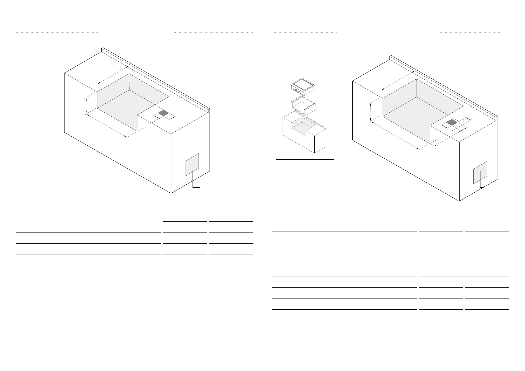
CUTOUT DIMENSIONS
STANDARD CUTOUT INSULATED JACKET CUTOUT
If the unit is to be placed into a combustible enclosure, an insulated jacket is required.
b
a
e
d
c
ventilation ventilation
GDE1-30 MODELS
CUTOUT DIMENSIONS
INCHES MM
A Height of cutout 10 1/8 257
B Depth of cutout 22 3/4 578
C Width of cutout 28 1/2 724
D Depth of gas supply opening 4 102
E Width of gas supply opening 4 15/16 125
Notes:
• When determining a suitable location, take into account concerns such as exposure to wind, proximity to traffic paths,
and keeping any gas supply lines as short as possible.
• Locate the unit in a well-ventilated area.
• The counter and supporting ledges or deck must be level and flat.
• The enclosure should have ventilation holes to prevent gas build-up in the event of a leak. Refer to ANSI Z21.58
Standard for Outdoor Cooking Gas Appliances, Section 1.7 Enclosures For Self Contained LP-Gas Supply Systems.
b
a
g
e
d
c
f
GDE1-30 MODELS
CUTOUT DIMENSIONS
INCHES MM
A Height of cutout 11 1/8 283
B Depth of cutout 23 3/4 603
C Width of cutout 34 7/8 886
D Depth of gas supply opening 4 102
E Width of gas supply opening 4 102
F Depth to gas supply opening from front of cutout 18 1/2 470
G Width to gas supply opening from side of cutout 3 1/2 89
Notes:
• Use only the DCS insulated jacket which has specifically been designed and tested for this purpose.
• To purchase access doors and drawers, visit dcsappliances.com
• 30” access doors model number: ADN1-30
• 30” access drawers model number: ADR2-30
4
Page 7
Clearances to non-combustible construction
Material which is not capable of being ignited and burned, such as
materials consisting entirely of, or a combination of, steel, iron, brick
tile, concrete, slate, and plaster.
The griddle is designed for easy placement into built-in masonry
enclosures. For non-combustible applications the unit drops into
the opening and hangs from its side flanges. A deck is not required
to support it from the bottom.
Fisher&Paykel recommends installing the manual shut-off valve
in a location readily accessible by the customer, so that gas to the
appliance can be shut off in an emergency situation. However, the
appliance must not be modified in any way to accommodate such
placement.
A level should be used to ensure that the unit is level both frontto-back and side-to-side. If it is not level, burner combustion may
be erratic or the unit may not function efficiently for grease flow.
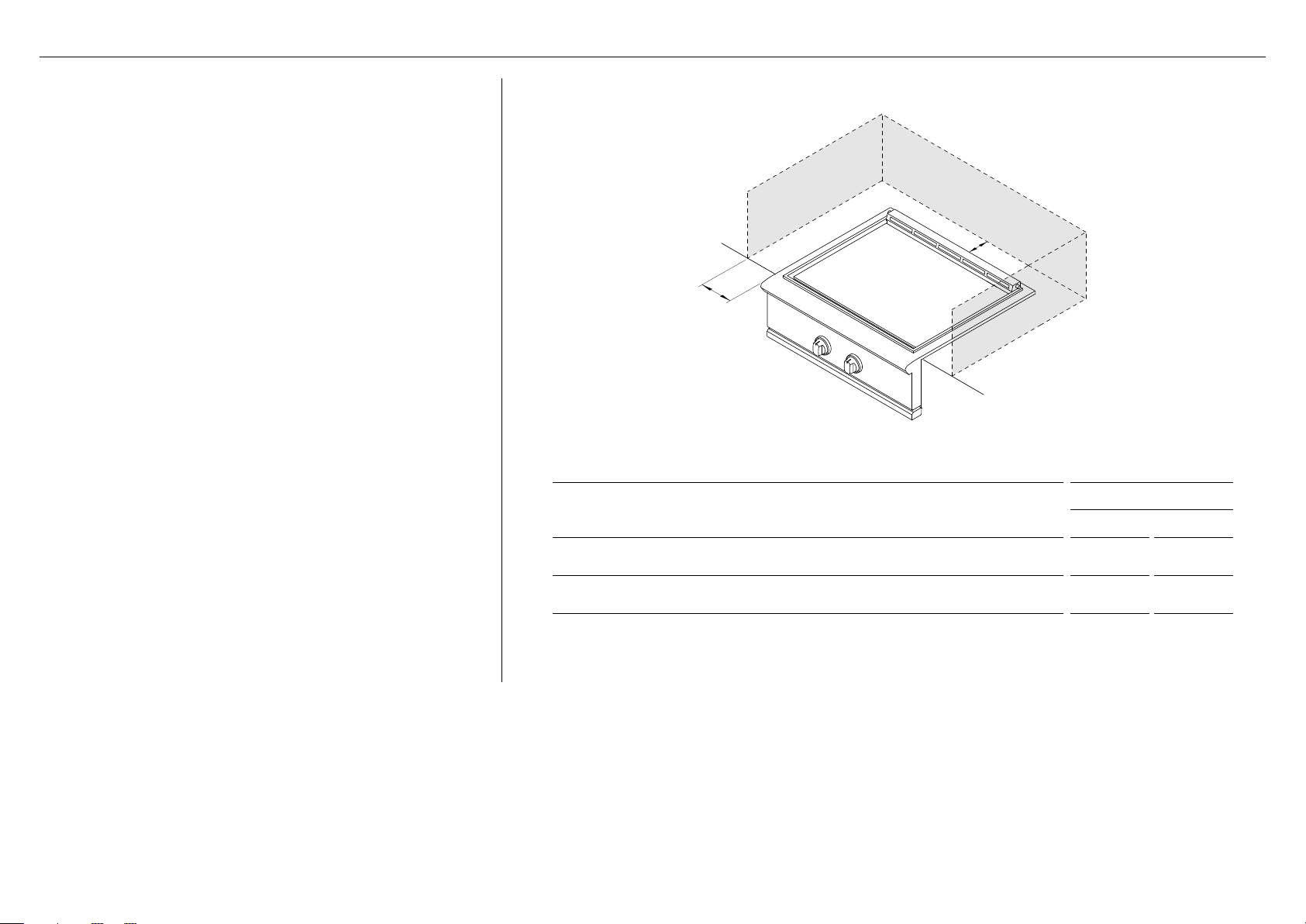
BUILT-IN CLEARANCES
B
a
CLEARANCE DIMENSIONS
Minimum distance from non-combustible construction to rear of griddle
A
(above counter)
Minimum distance from non-combustible construction to sides of griddle
B
(above counter)
GDE1-30 MODELS
INCHES MM
3 76
6 152
5
Page 8

Clearances to combustible construction
Any materials of a building structure or decorative structure made
of wood, compressed paper, plant fibres, vinyl/plastic or other
materials that are capable of transferring heat or being ignited
and burned. Such material shall be considered combustible even
though flame-proofed, fire-retardant treated or surface-painted,
or plastered.
Do not use this appliance under unprotected overhead
combustible surfaces.
BUILT-IN CLEARANCES
Insulated jacket
If the griddle is to be placed into a combustible enclosure, an
approved insulated jacket is necessary. Insulated jackets are
available from your dealer. Use only the DCS insulated jacket
which has specifically been designed and tested for this purpose.
Review the detail drawing shown and take into account the
provisions shown for gas line connection clearance in the right
rear corner. It is required that ventilation holes are provided in the
enclosure to eliminate the potential build-up of gas in the event
of a gas leak. The supporting ledges or deck must be level and
flat and strong enough to support the grill and insulated jacket.
The counter should also be level.
30” insulated jacket part number: 70859
a
CLEARANCE DIMENSIONS
Minimum distance from combustible construction to rear of griddle
A
(above counter)
Minimum distance from combustible construction to sides of griddle
B
(above counter)
B
GDE1-30 MODELS
INCHES MM
12 305
12 305
6
Page 9

GRIDDLE PLATE
Excessive weight Hazard
Two or more persons are required to handle the griddle plate.
Ensure the griddle plate is removed before moving the product to the installation location.
Removing the griddle plate
Remove the vent assembly
1
front of griddle rear of griddle
2
by pulling up gently from the
product, and set aside on a
protected surface.
Grip the griddle plate from under
the brackets at the front and rear
of the product as shown.
Replacing the griddle plate
1
2
Grip the front and rear of the
plate. Lower the plate to slot
back in place onto the product
ensuring it is centered.
Replace the vent assembly by
slotting the flash tubes back
gently into the support brackets
and lowering.
3
Lift up the griddle assembly and
set aside on a protected surface.
7
Page 10
All units are supplied with a 12V power transformer to operate the
products ignition and dial illumination features. The transformer is
sealed in a box with an attached power supply cord.
Electrical requirements
Use only a Ground Fault Interrupter (GFI) protected circuit with
this product.
An outdoor 120VAC 15A GFI electrical outlet should be installed
by a qualified electrician either inside the island enclosure for
built-in units, or near the location where a free-standing unit
will be used. For built-in products, the supplied 12V transformer
should be connected during installation.
Installation
The transformer must be secured below the product in a dry
location away from any excessive heat. Be sure to provide
adequate access to facilitate service if the transformer or
connections require maintenance.
Dial halos
When a dial is in use, an orange halo around that dial will
illuminate. This will change from orange to white if the dial is
turned to
OFF but another dial remains active. If all dials are
turned OFF, all halos will dim.
Multiple DCS Series 9 products may be linked together to allow
for cross-product halo illumination. To allow for this functionality,
an approved DCS kit is required and can be purchased separately
from your local DCS dealer.
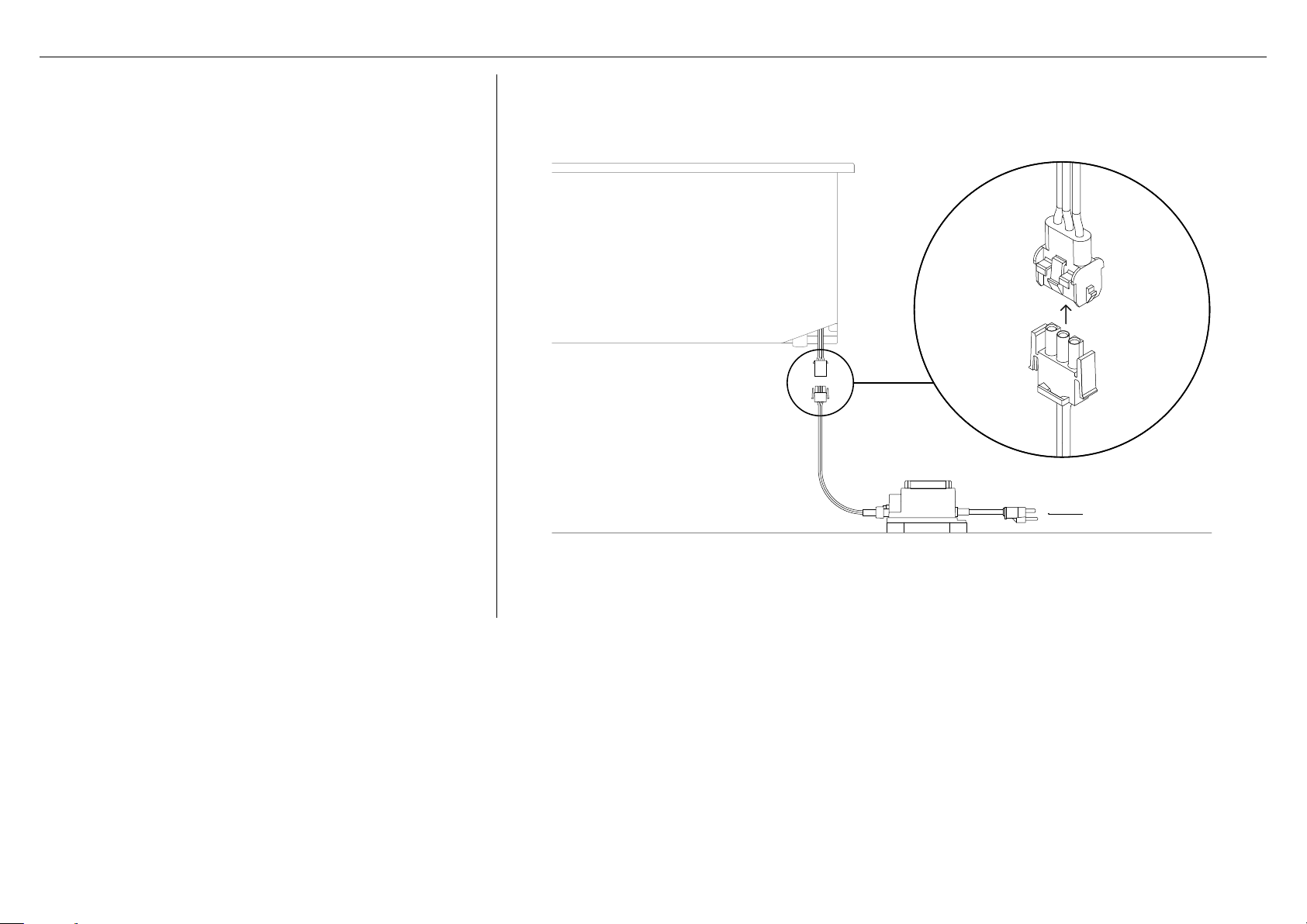
ELECTRICAL CONNECTION
TO OUTLET
If the ignition or dial halos fail to operate, a connection may
have come loose during installation or the GFI may have tripped
requiring a reset. Refer to the troubleshooting section of your
user guide for further guidance.
8
Page 11
GAS CONNECTION
GAS REQUIREMENTS NATURAL GAS CONNECTION
Verify the type of gas supply to be used, either natural or LP, and make sure the marking
on the appliance rating plate agrees with that of the supply. The rating plate is located on
the underside of the drip tray. Never connect an unregulated gas line to the appliance. You
must use a gas regulator even if the supply is controlled.
Gas conversion kits are available from Customer Care. When ordering gas conversion kits,
have the model number, and the type of gas (natural or LP) from your griddle.
The appliance and its individual shut-off valve must be disconnected from the gas supply
piping system during any pressure testing of that system at test pressures in excess of
1/2 PSIG (3.5 kPa.) The appliance must be isolated from the gas supply piping system by
closing its individual manual shut-off valve during any pressure testing of the gas supply
piping system at test pressures equal to or less than 1/2 PSIG (3.5 kPa.).
Total gas consumption of the griddle with all burners on HI
GDE1: 40,000 Btu/hr
Note:
z
If it is evident there is excessive abrasion or wear, or the hose is cut, it must be
replaced prior to the outdoor cooking gas appliance being put into operation.
z
The replacement hose assembly shall be that specified by the manufacturer.
Connection: 1/2” NPT male with 3/8” flare adapter Operating pressure: 4.0” W.C.
Supply pressure: 5” to 14” WC. If in excess of 14” W.C. a step down regulator is required.
Check with your local gas utility company or local codes for instructions on installing gas
supply lines. Be sure to check on type and size of run, and how deep to bury the line. If the
gas line is too small, the griddle will not function properly. Any joint sealant used must be
an approved type and be resistive to the actions of LP gases.
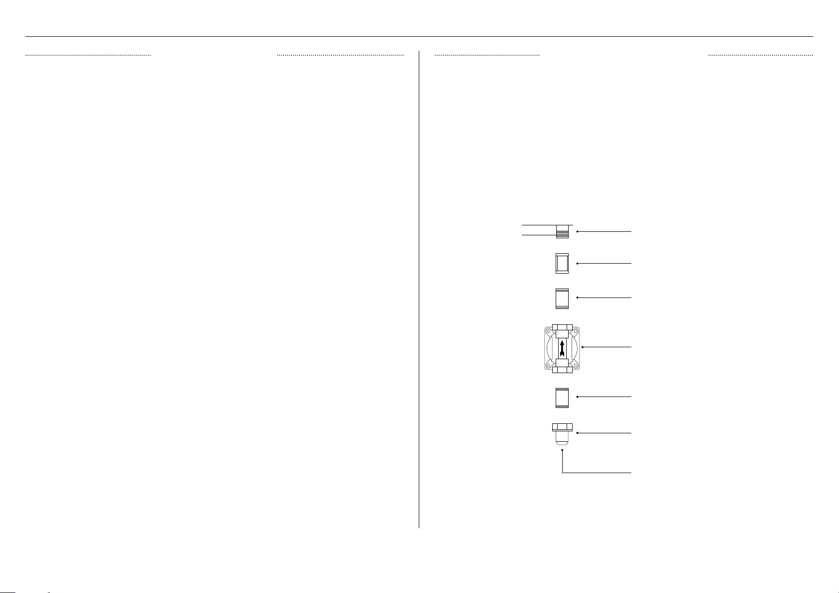
Connecting the fittings supplied with the griddle
Use joint compound on male threads only. Do not use joint compound on the flare end of
the 1/2” NPT to 3/8” flare adapter. Ensure that the regulator arrow points in the direction
of gas flow towards the unit, away from the supply. Do not forget to place the installersupplied gas valve in an accessible location.
base of product
open top manifold
1/2” coupling
1/2” NPT x 2.0 nipple
Regulator
1/2” NPT x 5.0 nipple
1/2” NPT to 3/8”
flare adapter
to gas supply
9
Page 12

GAS CONNECTION
CART LP CONNECTION
Units set for use with LP gas come equipped with a high capacity hose/regulator assem bly
for connection to a standard 20 lb. LP cylinder (Type 1). The LP tank is not included. The grill
system is leak tested, do not remove the Regulator/Hose assembly from the product during
cart installation.
Connection: LP Hose with a type 1 quick disconnect and regulator. Operating pressure: 11.0”W.C.
Connecting LP regulator/hose assembly to the tank/valve assembly
First, ensure the main valve on the tank is completely closed, all burner dials are in the OFF
position and the cart is stable. Although the flow of gas is stopped when the Type 1 system is
disconnected as part of its safety feature, you should always turn off the LP tank main valve
after each use and during transport of the tank or unit.
Open the tank drawer of the cart and place the LP tank into the tank retention device (as
shown in the cart installation guide). Insert the regulator inlet into the tank valve and turn
the black coupler clockwise until it tightens. Do not over tighten the coupler. Turn the main
tank valve
system to purge. Turn valves OFF and wait 5 minutes before attempting to ignite the burners.
Threading compound must
be resistant to LP gas
type 1 regulator
ON and the burner control valves to HI for about 20 seconds to allow the air in the
base of product
1/2” female NPT
x 3/8 male flare
(installed on unit)
BUILT-IN LP CONNECTION
If the grill is to be installed in a built-in application, then the grill must be installed in
accordance with the built–in installation guidelines and the LP regulator/hose assembly must
be removed from the product.
When an LP unit is being directly connected to an LP house system, you must follow the
natural gas connection guidelines. The installer must provide the proper gas regulator to
reduce the gas pressure to 11” W.C.
Connection: LP Hose with a Type 1 quick disconnect and regulator. Operating pressure: 11.0” W.C.
To operate your built-in grill on LP gas utilizing a 20lb type 1 cylinder, then a built-in LP tank
restraint must be installed prior to initial use of the grill. The Installer must supply ½” ID Flex
hose and fixed pipe and a flare adaptor
adapter 3/8” flare
fitting 1/2” NPT female
LP regulator/
hose assembly
base of product
open top manifold
1/2” ID flex hose with 1/2”
NPT fittings*
main tank valve
to type 1 tank
LP regulator hose
assembly 11” W.C.
(installed on unit)
Changing the LP cylinder
Ensure the main tank valve is turned off before turning the coupler counter clockwise, the
inlet will then disengage. Remove the inlet from the tank valve opening. Your local LP filling
station should be equipped with the proper equipment to fill your tank.
Do not attempt to remove, repair or replace the regulator/hose assembly. This must be
done by qualified and licensed technician only.
10
20lb LP tank*
Tank retention
device*
1/2” NPT fixed pipe*
Enclosure wall
*not supplied
Page 13

LEAK TESTING
A complete gas tightness check must be performed at the installation site. Periodically check
the whole system for leaks, or immediately if the smell of gas is present.
Removing the valve panel
1
2
Remove all dials by pulling outwards.
Remove the 2 screws securing
the valve panel to the unit using
a Phillips screwdriver.
Testing for leaks
1
NG:
2
LP:
leak points
leak points
Prepare soap solution by combining
one part liquid detergent and one
part water. Pour into a spray bottle.
Ensure all control valves are in the
OFF position before turning the gas
supply ON.
leak points
Check all connections from the
supply line or LP cylinder by
applying the solution around the
connection, tubing and end of the
manifold. Soap bubbles will appear
where a leak is present.
3
Pull the valve panel down then
outward and unplug any wires.
If a leak is present
Immediately turn the gas supply
and recheck. If you cannot stop a gas leak turn the gas supply OFF and call your local gas
utility or the dealer you purchased the appliance from. Only parts recommended by the
manufacturer should be used on the side burner/griddle, substitution can void the warranty.
OFF and tighten any leaking connections. Turn gas ON,
11
Page 14

Flames should be blue and stable with no
yellow tips, excessive noise or lifting (Note:
LP units may have some yellow tipping). If
any of these conditions exist, check the air
shutter and burner ports are clear. If cleaning
these does not improve performance, the air
shutter can be adjusted.
1
2
3
FLAME HEIGHT ADJUSTMENT
AIR SHUTTER
Ensure the griddle is
To access the air shutters, remove
the griddle plate. Refer to page 7
for guidance.
With a screw driver, loosen the lock
screw on the face of the air shutter
so it can be adjusted. If the flame is
yellow turn the air shutter counterclockwise, if the flame is noisy and
tends to lift turn the air shutter
clockwise.
Reinstall the U-burner and light
to check. If the flame is blue and
stable, remove the burner, tighten
the air shutter screw and replace all
parts. If flame is still unstable, repeat
the above steps.
OFF and cool.
yellow tips
12
noisy/lifting
blue + stable
Page 15

FREESTANDING CART INSTALLATION (OPTIONAL)
Designed with flexibility in mind, the 30” griddle can be either built-in or mounted on a
freestanding cart. If the unit is to be placed onto a freestanding cart, an approved DCS
cart is required and can be purchased separately from your local DCS dealer.
CAD1-30 freestanding cart part number: 71432
IMPORTANT!
z
For further guidance, refer to the installation
guide provided with your freestanding cart.
z
Wear gloves when handling the cart, some
edges may be sharp.
z
Two or more people are required to move
and assemble the cart.
z
Push or pull the cart at the corners, do not
move by the drawers or handles.
z
To prevent tipping, do not push down on top
of the drawers.
z
For optimal use, this product should be
located on a level surface with minimum flat
area of 30x48” (762 x 1219mm). Any bumps,
cracks or protrusions should be less than 1/4”.
z
Do not overload the drawers. The maximum
rating of each drawer is 35lbs.
Preparing the griddle
Securing griddle to cart
1
2
cart bracket
fixed to side
of griddle
Remove the drip pan and any other
removable components from the
griddle.
Place the griddle on the cart by
locating the rear side tabs of the unit
with the slots on the cart. Lower the
griddle and locate the remaining tabs.
The griddle should sit flush on the
cart.
1
2
support bracket
(remove on
both sides)
cart bracket
(secure on
both sides)
Remove the support brackets from
the sides of the unit and replace with
the supplied cart mount brackets.
Secure cart mounting brackets
using four of the supplied 10-24 x
1/2” screws on each side.
3
Secure the griddle to the cart with
two Phillips-head screws at the rear
and three at the front.
Replace any components removed
in step 1 before referring to page 9
for gas connection advice.
13
Page 16

INSTALLER CHECKLIST
Read all installation instructions in this manual to see if the unit has been correctly installed.
Ensure that installation has been completed correctly before use.
Ensure that:
specified clearances are maintained to combustibles
proper enclosure ventilation has been verified
all internal packaging and any adhesive residue is removed
the burner is level and does not rock
dials turn freely, bezels centered
halo lighting is functioning correctly
all warning labels removed and supplied to customer for future reference
Complete and keep for safe reference:
flame has been adjusted
each burner lights satisfactorily - individually or with adjacent burner lit
the pressure regulator is connected and set for 4.0” W.C. Natural, 11.0” W.C. LP gas
the manual shut-off valve is installed and accessible
the unit has been tested and is free of leaks
the user is informed of gas supply shut-off valve location
Model
Serial No.
Purchase Date
Purchaser
Dealer Address
Installer’s Name
Installer’s Signature
Installation Company
Installation Date
14
Page 17

Page 18

DCSAPPLIANCES.COM
The product specifications in this document apply to the specific products
and models described at the date of issue. Under our policy of continuous
product improvement, these specifications may change at any time. You should
therefore check with your Dealer to ensure this booklet correctly describes the
© Fisher & Paykel Appliances 2019. All rights reserved.
product currently available.
US CA
592068A 11.19
Page 19

PLAQUE CHAUFFANTE
Modèles GDE1-0
GUIDE D’INSTALLATION
US CA
Page 20

CONSIGNES DE SÉCURITÉ ET MISES EN GARDE
!
DANGER
SI VOUS DÉCELEZ UNE ODEUR DE GAZ
!
MISE EN GARDE!
Risque de choc électrique
Le non-respect de cette consigne peut
entraîner un choc électrique ou la mort.
• Cet appareil est équipé d’une fiche à trois ou
quatre broches avec mise à la terre pour vous
protéger des chocs électriques; branchezla directement dans une prise électrique
correctement mise à la terre.
• Fermez l’alimentation en gaz de
l’appareil.
• Éteignez toute flamme nue.
• Ouvrez le couvercle.
• Si l’odeur persiste, éloignez-vous de
l’appareil et appelez immédiatement
votre fournisseur de gaz ou le service
d’incendie.
!
MISE EN GARDE
• Ne rangez et n’utilisez pas de
l’essence ou d’autres liquides et
vapeurs inflammables à proximité
de cet appareil ou de tout autre
appareil.
• Ne rangez pas de bouteille de GPL
déconnectée et inutilisée à proximité
de cet appareil ou de tout autre
appareil.
• Ne retirez jamais la broche de mise à la terre ou
n’utilisez jamais la fiche avec un adaptateur à
2broches.
• Utilisez uniquement des rallonges munies d’une
fiche à 3broches avec mise à la terre, prévues
pour la puissance électrique de l’équipement et
homologuées pour l’usage extérieur avec une
indication W-A.
• N’immergez pas le cordon ou les fiches dans
l’eau ou tout autre liquide.
!
MISE EN GARDE!
Risque d’incendie
Le non-respect de cette consigne peut
entraîner un incendie causant des blessures
graves, voire mortelles.
• Cet appareil est conçu uniquement pour une
utilisation à l’extérieur. Ne faites pas fonctionner
le brûleur latéral/la plaque chauffante sous
une construction combustible non protégée.
N’utilisez pas l’appareil dans des bâtiments,
garages, remises, passages recouverts,
structures couvertes ou autres espaces clos.
1
Page 21

CONSIGNES DE SÉCURITÉ ET MISES EN GARDE
!
MISE EN GARDE!
• Ne rangez jamais une bouteille de GPL de rechange
sous cet appareil ou à proximité de celui-ci.
• N’utilisez pas de papier d’aluminium pour recouvrir
les bacs d’égouttement. Cela peut compromettre la
circulation de l’air de combustion ou entraîner une
accumulation de chaleur excessive dans la zone de
commande, risquant de faire fondre les boutons ou
d’endommager les pièces d’allumage.
!
MISE EN GARDE!
Risque d’explosion
Le non-respect de cette consigne peut
entraîner des blessures ou la mort
• Si vous sentez une odeur de gaz, n’utilisez pas
l’appareil.
• N’essayez pas d’éteindre les feux de friture avec
de l’eau, car cela pourrait causer une explosion
de vapeur violente. Éteignez tous les brûleurs,
puis étouffez le feu ou la flamme, ou utilisez un
extincteur à poudre ou à mousse.
• Ne faites pas chauffer des contenants d’aliments
non ouverts tels que des boîtes de conserve–
l’accumulation de pression pourrait faire exploser
le contenant et provoquer des blessures.
!
MISE EN GARDE!
Risque de poids excessif
Le non-respect de cette consigne peut
entraîner des blessures.
• Au moins deux personnes sont requises pour le
déplacement et l’installation de cet appareil ou
pour la manipulation de la plaque chauffante.
!
MISE EN GARDE!
Risque de surface brûlante
Le non-respect de cette consigne peut
entraîner un incendie, des brûlures, des
ébouillantages ou des blessures.
• Les pièces accessibles peuvent devenir brûlantes
pendant l’utilisation.
• Lors de l’utilisation, ne touchez pas le brûleur, la
grille ou les environs immédiats, car ces zones
deviennent extrêmement brûlantes. Nettoyez
avec précaution.
• Ne laissez jamais les vêtements et autres
matières inflammables se trouver trop près
ou entrer en contact avec des grilles, surfaces
brûlantes ou brûleurs avant qu’ils soient
refroidis.
• Ne vous penchez jamais au-dessus d’un appareil
ouvert. Lors de l’allumage d’un brûleur, portez
toujours une attention particulière à chaque
étape effectuée. Assurez-vous de bien enfoncer
le bouton du brûleur lorsque vous tentez de
l’allumer.
• Gardez les cordons d’alimentation électrique et
le tuyau d’alimentation en combustible à bonne
distance de toute surface chaude.
• Assurez-vous que toutes les commandes sont
à la position d’arrêt et que l’appareil est froid
avant d’utiliser un type quelconque de produit
nettoyant en aérosol sur le produit ou autour
de celui-ci. Les produits chimiques servant à la
pulvérisation pourraient, en présence de chaleur,
s’enflammer ou provoquer la corrosion des
pièces métalliques
2
Page 22

CONSIGNES DE SÉCURITÉ ET MISES EN GARDE
!
MISE EN GARDE!
• Ne faites jamais fonctionner l’appareil sans
plateau d’égouttement. Laissez refroidir
la graisse chaude avant de tenter toute
manipulation. Évitez de laisser les dépôts de
graisse s’accumuler dans le bac d’égouttement.
MISE EN GARDE!
Pour réduire les risques d’incendie, de blessures ou de dommages lors de l’utilisation de
l’appareil, respectez les consignes de sécurité importantes indiquées ci-dessous. Lisez
toutes les instructions avant d’utiliser l’appareil. N’utilisez pas un appareil de cuisson au gaz
d’extérieur à d’autres fins que celles prévues.
Entretien
z
Ne réparez ou remplacez aucune pièce de cet appareil, à moins que ce ne soit
spécifiquement recommandé dans le guide d’utilisation. Tous les autres travaux doivent
être effectués par un technicien de service formé et supporté par Fisher&Paykel ou une
personne qualifiée.
z
Utilisez uniquement le produit avec le type de gaz spécifié sur la plaque signalétique.
Risque d’incendie
z
Utilisez uniquement l’appareil dans des zones bien ventilées.
z
Ne laissez jamais le produit sans surveillance pendant l’utilisation.
z
Retirez toujours le couvercle avant l’allumage. Ne remettez pas le couvercle en place
pendant la cuisson ou avant que l’appareil ait refroidi.
z
N’utilisez jamais une flamme pour vérifier s’il y a des fuites de gaz.
z
N’essayez pas de déconnecter des raccordements de gaz pendant que votre appareil est
en cours d’utilisation ou que l’alimentation en gaz est ouverte.
z
Ne connectez jamais de conduite de gaz non régulée à l’appareil.
z
Ayez un extincteur de classe ABC à portée de la main– ne tentez jamais d’éteindre un feu
de friture avec de l’eau ou d’autres liquides.
Rangement
z
Lorsque l’appareil n’est pas utilisé, assurez-vous que l’alimentation en gaz est fermée à la
bouteille d’alimentation.
z
Gardez l’appareil couvert lorsqu’il n’est pas utilisé.
z
Il est possible de ranger l’appareil à l’intérieur uniquement si la bouteille est déconnectée
et retirée de l’appareil.
z
Les bouteilles doivent être rangées à l’extérieur, hors de la portée des enfants; elles ne
doivent pas se trouver dans un bâtiment, un garage ou tout autre endroit clos.
z
N’entreposez pas de bouteille de GPL pleine à la lumière directe du soleil.
z
Après une période de rangement ou d’inutilisation, vous devez vérifier l’appareil avant
de l’utiliser pour confirmer l’assemblage adéquat et l’absence de fuites de gaz, de
détérioration et d’obstruction au niveau des brûleurs.
Utilisation générale
z
Cet appareil n’est pas conçu pour être installé dans ou sur des véhicules récréatifs,
remorques ou bateaux.
z
Après l’allumage des brûleurs, assurez-vous qu’ils fonctionnent correctement.
z
Lors de l’utilisation de l’appareil, assurez-vous que toutes les pièces sont fermement en
place et que l’ensemble de l’appareil est stable.
z
Ne déplacez pas l’appareil pendant l’utilisation.
z
Les enfants ne doivent pas être laissés seuls ou sans surveillance à proximité de
l’endroit où le produit est utilisé. Ne laissez jamais les enfants s’asseoir, se tenir ou jouer
sur l’appareil ou à proximité de celui-ci à un moment quelconque.
z
Ne rangez pas d’articles pouvant attirer les enfants à proximité ou en dessous de
l’appareil.
z
N’utilisez jamais l’appareil dans un endroit venteux.
z
Pour éteindre des flambées soudaines, ajustez les commandes pour abaisser la
température.
z
N’obstruez pas le débit de combustion et de ventilation de l’appareil.
z
Les araignées et insectes peuvent faire leur nid dans les brûleurs ou les ouvertures et
ainsi bloquer ou limiter le débit du brûleur. Cela peut provoquer un retour de flamme au
niveau du panneau de commande, risquant de provoquer un incendie.
z
N’essayez pas d’allumer cet appareil avant d’avoir lu les instructions d’allumage dans le
guide d’utilisation.
z
Ne placez, ne rangez ou n’utilisez pas l’appareil sur une pente.
z
Dans le Commonwealth du Massachusetts, ce produit doit être installé par un monteur
d’installation au gaz ou plombier autorisé.
z
Ne remplissez pas le réservoir de gaz à plus de 80% de sa capacité totale.
z
N’utilisez jamais de réservoir de GPL bosselé ou rouillé. Gardez les ouvertures de
ventilation de l’enceinte de la bouteille dégagées et exemptes de débris.
z
Avant chaque utilisation, inspectez la tuyauterie ou le tuyau d’alimentation en gaz avant
d’ouvrir le gaz (ON). Si vous remarquez la présence de coupures, d’usure ou d’abrasion,
il doit être remplacé avant l’utilisation. Vous devez utiliser l’assemblage de régulateur
de pression et tuyau fourni avec l’appareil. Pour tout remplacement, communiquez avec
le service à la clientèle sur le site www.dcsappliances.com
z
Nettoyez et effectuez régulièrement l’entretien général de l’appareil. Surveillez toute
apparition de corrosion, de fissures ou d’activité d’insectes. Vérifiez soigneusement le
régulateur, les tuyaux, les orifices de brûleurs, l’obturateur d’air et la section venturi/
valve. Fermez toujours le gaz à la source avant d’inspecter les pièces.
z
Vous devez inspecter l’appareil au moins une fois par année ou immédiatement si une
odeur de gaz est présente et les flammes de brûleur sont de couleur jaune, si l’appareil
n’atteint pas la température réglée ou ne chauffe pas uniformément ou si l’appareil
produit des bruits de claquement.
z
Ne fumez pas pendant la vérification des fuites et éteignez toutes les flammes nues.
z
Pendant le nettoyage des brûleurs, centrez correctement les brûleurs sur leur orifice
et assurez-vous qu’ils soient de niveau avant de procéder à l’allumage pour éviter
les risques d’incendie ou d’explosion. Reportez-vous au guide d’utilisation pour des
instructions détaillées.
z
Utilisez uniquement un circuit protégé par un disjoncteur différentiel de fuite à la terre
(DDFT) avec cet appareil de cuisson au gaz d’extérieur.
z
Débranchez l’appareil de la prise de courant lorsqu’il n’est pas utilisé et avant de le
nettoyer. Laissez-le refroidir avant d’installer ou de retirer des pièces.
3
Page 23

CONSIGNES DE SÉCURITÉ ET MISES EN GARDE
z
Ne faites pas fonctionner l’appareil avec une fiche ou un cordon d’alimentation
endommagé, après un problème de fonctionnement ou si l’appareil est endommagé
de quelque manière que ce soit. Communiquez avec le fabricant pour demander une
réparation.
z
Ne laissez pas le cordon pendre sur le côté d’une table ou toucher des surfaces brûlantes.
z
Lors du raccordement, connectez d’abord la fiche à l’appareil, puis branchez l’appareil à la
prise de courant.
z
Ne placez pas l’appareil directement sur le sol ou toute surface sans support. Cela évitera
d’endommager l’assemblage de régulateur/tuyau.
Exigences relatives à l’alimentation en gaz
z
Cet appareil peut être utilisé avec un réservoir de GPL de 20lb de n’importe quelle
marque, à condition qu’il soit compatible avec un dispositif de retenue adéquat (non
fourni).
z
Cet appareil est réglé pour l’utilisation avec du gaz de pétrole liquéfié (GPL) ou du gaz
naturel (GN); le type est déterminé au point de vente.
z
La bouteille de GPL doit être:
z
Conçue pour l’utilisation avec un système de Type1 uniquement.
z
Fabriquée et marquée conformément aux spécifications applicables aux bouteilles de
GPL du ministère des Transports des États-Unis (D.O.T.) ou à la norme Bouteilles et
tubes pour le transport des matières dangereuses et commission, CAN/CSA-B339
z
Fournie avec un dispositif limiteur de remplissage homologué.
z
Fournie avec un dispositif de raccordement de bouteille compatible avec les raccords
pour appareils de cuisson au gaz d’extérieur
z
La bouteille doit posséder un robinet d’arrêt terminé par une sortie de robinet
d’alimentation en GPL spécifiée, selon le cas, pour un raccordement de Type1.
z
Ne changez pas l’assemblage de régulateur/tuyau fourni avec l’appareil ou n’essayez pas
d’utiliser un assemblage de régulateur/tuyau de Type1 avec un assemblage de réservoir/
robinet 510POL standard.
z
N’utilisez jamais une bouteille dont le robinet est endommagé. La bouteille utilisée doit
être munie d’un collet permettant de protéger le robinet de la bouteille.
z
Un robinet d’arrêt de gaz fourni par l’installateur doit être installé dans un endroit
facilement accessible
z
Toutes les pièces fournies par l’installateur doivent être conformes aux codes locaux, ou
en l’absence de codes locaux, à la norme ANSI/NFPA70 du National Electrical Code ou la
norme CSA C22.1 du Code canadien de l’électricité, et à la norme ANSIZ223.1 du National
Fuel Gas Code ou la norme CSA-B149.1 du Code d’installation du gaz naturel ou CSAB149.2 du Code d’installation du propane.
z
Au Massachusetts, de tels robinets d’arrêt doivent être approuvés par le Board of State
Examiners of Plumbers&Gas Fitters.
z
Le scellant d’étanchéité de toutes les conduites doit être d’un type approuvé et résistant à
l’action des gaz de pétrole liquéfié. N’utilisez jamais de scellant d’étanchéité de conduite
sur des raccords coniques.
z
Un réservoir de GPL bosselé ou rouillé peut être dangereux; vous devez le faire vérifier par
votre fournisseur de GPL.
z
Vérifiez toujours s’il y a des fuites après chaque changement de réservoir de GPL.
z
Pour les appareils au GPL, effectuez la vérification des fuites avec une bouteille pleine.
z
N’utilisez pas l’appareil avant la vérification de tous les raccordements pour confirmer
l’absence de fuites.
CONSERVEZ CES INSTRUCTIONS
Les modèles illustrés dans ce guide d’installation peuvent ne pas être disponibles dans tous les pays
et sont sujets à modifications sans préavis. Pour les plus récentes informations sur la disponibilité des
modèles et des caractéristiques dans votre pays, veuillez visiter notre site Web dcsappliances.com ou
contacter votre détaillant DCS local.
4
Page 24

DIMENSIONS DU PRODUIT
a
e
b
AVANT
j
g
f
h
DIMENSIONS DU PRODUIT
A Hauteur hors tout (excluant les brûleurs et les pièces d’appui) 10 1/2 266
D
i
PROFIL
MODÈLES GDE1
POUCES MM
k
l
B Largeur hors tout 30 762
C Profondeur hors tout (excluant les boutons) 267/8 683
D Profondeur du châssis 221/2 572
c
PLAN
5
E Largeur du châssis (incluant le support) 2713/16 707
F Hauteur sous le comptoir 101/8 257
G Hauteur de la surface au-dessus du comptoir 9/16 14
H Profondeur du panneau de commande jusqu’à l’avant du châssis 23/16 56
I Profondeur du panneau de commande jusqu’à l’arrière du produit 251/2 647
J Profondeur du couvercle 2215/16 583
K Largeur du couvercle 291/2 750
L Hauteur du couvercle 291/2 43
Page 25

DIMENSIONS DE LA DÉCOUPE
DÉCOUPE STANDARD DÉCOUPE AVEC ENVELOPPE ISOLÉE
Si l’appareil doit être placé dans une enceinte combustible, une enveloppe isolée est requise.
b
a
e
d
c
ventilation ventilation
MODÈLES GDE1-30
DIMENSIONS DE LA DÉCOUPE
POUCES MM
A Hauteur de la découpe 101/8 257
B Profondeur de la découpe 223/4 578
C Largeur de la découpe 281/2 724
D Profondeur de l’ouverture pour l’alimentation en gaz 4 102
E Largeur de l’ouverture pour l’alimentation en gaz 415/16 125
Remarques:
• Au moment de déterminer un endroit adéquat, tenez compte de divers critères tels que l’exposition au vent, la proximité
de trajets de circulation et la nécessité de garder les conduites d’alimentation en gaz aussi courtes que possible.
• Placez l’appareil dans un lieu bien aéré.
• Le comptoir et les pièces d’appui ou la base de support doivent être de niveau et à plat.
• L’enceinte doit comporter des ouvertures de ventilation pour éviter l’accumulation de gaz en cas de fuite. Reportez-vous
à la norme ANSI Z21.58 pour Appareils de cuisson au gaz d’extérieur, Section 1.7 Enceintes pour systèmes autonomes
d’alimentation en gaz de pétrole liquéfié.
b
a
g
e
d
c
f
MODÈLES GDE1-30
DIMENSIONS DE LA DÉCOUPE
POUCES MM
A Hauteur de la découpe 111/8 283
B Profondeur de la découpe 233/4 603
C Largeur de la découpe 347/8 886
D Profondeur de l’ouverture pour l’alimentation en gaz 4 102
E Largeur de l’ouverture pour l’alimentation en gaz 4 102
F Profondeur de l’ouverture pour l’alimentation en gaz
à partir du devant de la découpe
G Largeur de l’ouverture pour l’alimentation en gaz à
partir du côté de la découpe
Remarques:
• Utilisez uniquement l’enveloppe isolée DCS ayant été conçue et testée spécialement pour cet usage.
• Pour vous procurer des portes et tiroirs d’accès, visitez le site dcsappliances.com
• Numéro de modèle des portes d’accès de 30”: ADN1-30
• Numéro de modèle des tiroirs d’accès de 30”: ADR2-30
181/2 470
31/2 89
6
Page 26

Dégagements pour une construction incombustible
Matériau ne pouvant pas être enflammé et brûlé, comme les
matériaux composés entièrement, ou constitués d’une combinaison,
d’acier, de fer, de brique, de tuile, de béton, d’ardoise et de plâtre.
La plaque chauffante est conçue pour s’installer facilement dans
les enceintes de maçonnerie encastrées. Pour les emplacements
incombustibles, l’appareil est inséré dans l’ouverture et suspendu
par ses brides latérales. Il n’est pas nécessaire de le soutenir par le
bas.
Fisher&Paykel recommande d’installer le robinet d’arrêt manuel
dans un endroit facilement accessible par le client afin qu’il
puisse fermer l’alimentation en gaz de l’appareil en cas d’urgence.
Toutefois, l’appareil ne doit être modifié d’aucune façon pour
permettre un tel positionnement.
Utilisez un niveau à bulle pour vous assurer que l’appareil est bien
de niveau de l’avant à l’arrière et d’un côté à l’autre. S’il n’est pas
de niveau, la combustion du brûleur risque d’être erratique ou
l’écoulement des graisses pourrait ne pas s’effectuer efficacement.
DÉGAGEMENTS DE L’APPAREIL ENCASTRÉ
B
a
DIMENSIONS DE DÉGAGEMENT
Distance minimale entre une construction incombustible et l’arrière de la plaque
A
chauffante (au-dessus du comptoir)
Distance minimale entre une construction incombustible et les côtés de la
B
plaque chauffante (au-dessus du comptoir)
7
MODÈLES GDE1-30
POUCES MM
3 76
6 152
Page 27

Dégagements pour une construction combustible
Tout matériau de structure de construction ou structure
décorative en bois, papier comprimé, fibres de plante, vinyle/
plastique ou autres matériaux capables de transférer la chaleur ou
pouvant être enflammés et brûlés. Un tel matériau sera considéré
comme combustible même s’il est ignifugé, traité pour retarder la
propagation des flammes ou recouvert de peinture ou plâtre.
N’utilisez pas cet appareil sous des surfaces combustibles non
protégées en surplomb.
DÉGAGEMENTS DE L’APPAREIL ENCASTRÉ
Enveloppe isolée
Si la plaque chauffante doit être placée dans une enceinte
combustible, une enveloppe isolée homologuée est requise. Des
enveloppes isolées sont disponibles auprès de votre détaillant.
Utilisez uniquement l’enveloppe isolée DCS ayant été conçue et
testée spécialement pour cet usage. Consultez le schéma détaillé
et tenez compte des dimensions de dégagement indiquées pour
le raccordement de la conduite de gaz dans le coin arrière droit.
Il est nécessaire de prévoir des ouvertures de ventilation dans
l’enceinte pour éviter le risque d’accumulation de gaz en cas de
fuite. Les pièces d’appui ou la base de support doivent être de
niveau, à plat et suffisamment solides pour supporter le gril et
l’enveloppe isolée. Le comptoir doit également être de niveau.
Numéro de pièce de l’enveloppe isolée de 30”: 70859
B
a
DIMENSIONS DE DÉGAGEMENT
Distance minimale entre une construction combustible et l’arrière de la plaque
A
chauffante (au-dessus du comptoir)
Distance minimale entre une construction combustible et les côtés de la plaque
B
chauffante (au-dessus du comptoir)
MODÈLES GDE1-30
POUCES MM
12 305
12 305
8
Page 28

PLAQUE CHAUFFANTE
Risque de poids excessif
Au moins deux personnes sont requises pour manipuler la plaque
chauffante.
Il est nécessaire de retirer la plaque chauffante pour accéder aux brûleurs afin d’effectuer le
nettoyage régulier, pour régler la hauteur de la flamme ou avant de déplacer le produit.
Retrait de la plaque chauffante
Retirez l’assemblage d’évent
1
2
avant de la plaque
chauffante
arrière de la plaque
chauffante
en le soulevant délicatement
du produit, puis mettez-le de
côté sur une surface protégée.
Saisissez la plaque chauffante
en la tenant par le dessous des
supports à l’avant et l’arrière du
produit, comme illustré.
Réinstallation de la plaque chauffante
1
2
Saisissez l’avant et l’arrière de
la plaque. Abaissez la plaque
pour la réinsérer en place sur
le produit, en vous assurant
qu’elle soit bien centrée.
Réinstallez l’assemblage
d’évent en réinsérant
délicatement les tubes éclairs
dans les supports, puis en
abaissant l’assemblage.
3
9
Soulevez l’assemblage de plaque
chauffante et mettez-le de côté
sur une surface protégée.
Page 29

Tous les appareils sont fournis avec un transformateur
d’alimentation 12V permettant le fonctionnement du dispositif
d’allumage et des fonctions d’éclairage des boutons. Le
transformateur est scellé dans un boîtier avec un cordon
d’alimentation électrique raccordé.
Exigences électriques
Utilisez uniquement un circuit protégé par un disjoncteur
différentiel de fuite à la terre (DDFT) avec ce produit.
Une prise électrique 120VCA 15A extérieure avec DDFT doit
être installée par un électricien qualifié à l’intérieur de l’enceinte
pour les appareils encastrés, ou à proximité du lieu d’utilisation
pour un appareil non encastré. Pour les produits encastrés,
le transformateur 12V fourni doit être raccordé pendant
l’installation.
Installation
Le transformateur doit être fixé sous le produit, dans un
emplacement sec et éloigné de toute chaleur excessive. Assurezvous de prévoir un accès adéquat pour faciliter l’entretien si le
transformateur ou les raccordements devaient nécessiter des
travaux de maintenance.
Halos de boutons
Lorsqu’un bouton est en cours d’utilisation, un halo orange
s’allume autour de ce bouton. Il passe d’orange à blanc si le
bouton est tourné à la position
OFF (ARRÊT), mais qu’un autre
bouton demeure activé. Si tous les boutons sont tournés à la
position OFF (ARRÊT), tous les halos sont atténués.
Il est possible de relier plusieurs produits DCS de Série9 afin de
permettre l’illumination de halos entre les différents produits.
Pour utiliser cette fonctionnalité, un ensemble DCS approuvé est
requis et disponible séparément auprès de votre détaillant DCS
local.
RACCORDEMENT ÉLECTRIQUE
VERS LA PRISE
Si le dispositif d’allumage ou les halos de boutons ne fonctionnent
pas, il est possible qu’un branchement se soit desserré lors de
l’installation ou que le DDFT se soit déclenché et nécessite un
réenclenchement. Reportez-vous à la section de dépannage de
votre guide d’utilisation pour davantage d’instructions.
10
Page 30

RACCORDEMENT DU GAZ
RACCORDEMENT DE GAZ NATURELEXIGENCES RELATIVES À L’ALIMENTATION EN GAZ
Vérifiez le type d’alimentation en gaz à utiliser (gaz naturel ou GPL) et assurez-vous
que l’indication figurant sur la plaque signalétique de l’appareil est conforme à celle de
l’alimentation. La plaque signalétique est apposée sous le plateau d’égouttement. Ne
connectez jamais de conduite de gaz non régulée à l’appareil. Vous devez utiliser un
régulateur de pression même si l’alimentation en gaz est contrôlée.
Des ensembles de conversion de gaz sont disponibles auprès du service à la clientèle.
Au moment de commander des ensembles de conversion de gaz, indiquez le numéro de
modèle et le type de gaz (naturel ou GPL) de votre plaque chauffante.
L’appareil et son robinet d’arrêt individuel doivent être débranchés du système de
tuyauterie d’alimentation en gaz pendant toute vérification de pression de ce système à
des pressions d’essai supérieures à 1/2PSIG (3,5kPa). Fermez le robinet d’arrêt manuel
individuel de l’appareil pour l’isoler du système de tuyauterie d’alimentation en gaz
pendant toute vérification de pression du système à des pressions d’essai égales ou
inférieures à 1/2PSIG (3,5kPa).
Consommation de gaz totale de la plaque chauffante avec tous les brûleurs réglés à HI
(ÉLEVÉ)
GDE1: 40000BTU/heure
Remarque:
z
Si vous constatez des signes évidents d’abrasion ou d’usure excessive, ou encore si le
tuyau est coupé, vous devez le faire remplacer avant d’utiliser l’appareil de cuisson au
gaz d’extérieur.
z
L’assemblage de tuyau de rechange spécifié par le fabricant doit être utilisé pour le
remplacement.
Raccordement: NPT 1/2” mâle avec adaptateur évasé de 3/8” Pression de fonctionnement:
4,0” C.E.
Pression d’alimentation: 5” à 14” C.E. Si la pression est supérieure à 14” C.E., vous devez
utiliser un régulateur abaisseur.
Communiquez avec votre fournisseur de gaz local ou consultez les codes locaux pour des
instructions sur l’installation des conduites d’alimentation en gaz. Assurez-vous de vérifier
le type et les dimensions de la conduite, ainsi que la profondeur d’enfouissement. Si la
conduite de gaz est trop petite, la plaque chauffante ne fonctionnera pas correctement.
Tout scellant à joint utilisé doit être d’un type approuvé et résistant à l’action des gaz de
pétrole liquéfié.
Pour connecter les raccords fournis avec la plaque chauffante
Utilisez de la pâte à joint sur les filetages mâles uniquement. N’appliquez pas de pâte à joint
sur l’extrémité évasée de l’adaptateur évasé NPT 1/2” vers 3/8”. Assurez-vous que la flèche
du régulateur pointe dans le sens du débit de gaz vers l’appareil, dans le sens opposé à
l’alimentation en gaz. N’oubliez pas de placer le robinet d’arrêt fourni par l’installateur dans
un endroit accessible.
base du produit
collecteur ouvert
manchon 1/2”
raccord NPT 1/2” x 2,0
Régulateur
raccord NPT 1/2” x 5,0
adaptateur évasé
NPT 1/2” vers 3/8”
vers l’alimentation en gaz
11
Page 31

RACCORDEMENT DU GAZ
RACCORDEMENT DE GPL POUR UN APPAREIL SUR CHARIOT RACCORDEMENT DE GPL POUR UN APPAREIL ENCASTRÉ
Les appareils réglés pour l’utilisation avec du GPL sont équipés d’un assemblage tuyau/
régulateur de haute capacité pour le raccordement à une bouteille de GPL standard de 20lb
(Type1). Le réservoir de GPL n’est pas compris. Le système de gril a été soumis à des essais
d’étanchéité; ne retirez pas l’assemblage de régulateur/tuyau du produit pendant l’installation
sur un chariot.
Raccordement: Tuyau pour GPL avec raccord à débranchement rapide de type1 et régulateur.
Pression de fonctionnement: 11,0” C.E.
Pour connecter l’assemblage de régulateur/tuyau de GPL à l’assemblage de réservoir/robinet
Assurez-vous d’abord que le robinet principal du réservoir est complètement fermé, que tous
les boutons de brûleur sont à la position
OFF (ARRÊT) et que le chariot est stable. Bien que
le débit de gaz soit interrompu lorsque le système de Type1 est déconnecté par mesure de
sécurité, fermez toujours le robinet principal du réservoir de GPL après chaque utilisation et
pendant le transport du réservoir ou de l’appareil.
Ouvrez le tiroir d’accès du chariot et placez le réservoir de GPL dans le dispositif de retenue
de réservoir (comme illustré dans le guide d’installation sur chariot). Insérez l’admission du
régulateur dans le robinet du réservoir et tournez le coupleur noir dans le sens des aiguilles
d’une montre pour le serrer. Ne serrez pas excessivement le coupleur. Ouvrez le robinet
principal du réservoir (
ON) et tournez les valves de réglage de brûleur à la position HI (ÉLEVÉ)
pendant environ 20secondes afin de purger l’air du système. Fermez les valves (OFF) et
attendez 5minutes avant d’essayer d’allumer les brûleurs.
Le composé pour filetage doit être résistant
à l’action du gaz de pétrole liquéfié
régulateur de
type1
robinet
principal du
réservoir de
type1
base du produit
NPT 1/2” femelle
x 3/8” mâle
évasé (installé
sur l’appareil)
assemblage de
régulateur/tuyau de
GPL 11” C.E. (installé
sur l’appareil)
Pour l’installation dans un emplacement encastré, il est nécessaire d’installer le gril
conformément aux directives d’installation encastrée et de retirer l’assemblage de régulateur/
tuyau de GPL du produit.
Lorsqu’un appareil au GPL est directement raccordé à un système d’alimentation en GPL
résidentiel, vous devez suivre les consignes de raccordement de gaz naturel. L’installateur doit
fournir un régulateur de pression approprié pour réduire la pression du gaz à 11” C.E.
Raccordement: Tuyau pour GPL avec raccord à débranchement rapide de Type1 et
régulateur. Pression de fonctionnement: 11,0” C.E.
Pour faire fonctionner votre gril encastré avec du GPL en utilisant une bouteille de 20lb de
type1, un dispositif de retenue de réservoir de GPL intégré doit être installé avant la première
utilisation du gril. L’installateur doit fournir un tuyau flexible de DI ½po, un tuyau fixe et un
adaptateur évasé
raccord NPT 1/2” femelle
avec adaptateur évasé 3/8”
assemblage de
régulateur/tuyau
de GPL
réservoir de
GPL de 20lb*
Dispositif de
retenue de
réservoir*
base du produit
collecteur ouvert
tuyau flexible de DI 1/2”
avec raccords NPT 1/2”*
tuyau fixe NPT 1/2”*
Mur de l’enceinte
*non fourni
Changement de bouteille de GPL
Assurez-vous de fermer le robinet principal du réservoir avant de tourner le coupleur dans
le sens inverse des aiguilles d’une montre pour désengager l’admission. Retirez l’admission
de l’ouverture de robinet du réservoir. Votre station locale de remplissage de GPL devrait
disposer de l’équipement approprié pour remplir votre réservoir.
N’essayez pas de retirer, réparer ou remplacer l’assemblage de régulateur/tuyau. Cela doit
être effectué uniquement par un technicien qualifié agréé.
12
Page 32

VÉRIFICATION DES FUITES
Une vérification d’étanchéité complète doit être effectuée sur le site d’installation. Vérifiez
périodiquement l’absence de fuites dans l’ensemble du système ou effectuez immédiatement
une vérification si vous sentez une odeur de gaz.
Retrait du panneau des valves
1
2
Retirez tous les boutons en les tirant
vers l’extérieur.
Utilisez un tournevis à tête étoilée
pour retirer les 2vis servant à
fixer le panneau des valves sur
l’appareil.
Vérification d’étanchéité
1
points de fuite
GN:
2
points de fuite
GPL:
Préparez une solution savonneuse,
composée d’une part de détergent
liquide et d’une part d’eau. Versez
la solution dans un vaporisateur.
Assurez-vous que toutes les valves
de réglage sont à la position OFF
(ARRÊT) avant d’ouvrir l’alimentation
en gaz à la position ON (MARCHE).
points de fuite
Vérifiez tous les raccordements de
la conduite d’alimentation ou de la
bouteille de GPL en appliquant la
solution autour du raccordement,
sur le tuyau et à l’extrémité du
collecteur. Des bulles de savon
apparaîtront en présence d’une
fuite.
3
13
Tirez le panneau des valves vers
le bas, puis vers l’extérieur et
débranchez les fils.
En présence d’une fuite
Fermez immédiatement l’alimentation en gaz à la position
raccordements présentant une fuite. Ouvrez l’alimentation en gaz à la position ON
(MARCHE), puis vérifiez de nouveau. Si vous ne parvenez pas à arrêter une fuite de gaz,
fermez l’alimentation en gaz à la position OFF (ARRÊT) et appelez votre fournisseur de
gaz local ou le détaillant auprès duquel vous avez acheté l’appareil. Seules les pièces
recommandées par le fabricant doivent être utilisées sur le brûleur latéral/la plaque
chauffante; toute substitution peut entraîner l’annulation de la garantie.
OFF (ARRÊT) et serrez les
Page 33

FLAME HEIGHT ADJUSTMENT
Les flammes doivent être bleues et stables,
sans pointe jaune, bruit excessif ou élévation
au-dessus du brûleur (Remarque: les
flammes des appareils au GPL peuvent avoir
certaines pointes jaunes). Si l’une de ces
situations se produit, vérifiez que l’obturateur
d’air et les orifices de brûleur sont dégagés.
Si le nettoyage de ces pièces n’améliore pas
les performances, il est possible d’ajuster
l’obturateur d’air.
1
2
3
OBTURATEUR D’AIR
Assurez-vous que la plaque
chauffante est à
refroidie.
Pour accéder aux obturateurs
d’air, retirez la plaque chauffante.
Reportez-vous à la page12 pour
les instructions.
À l’aide d’un tournevis, desserrez
la vis de blocage sur la face de
l’obturateur d’air de manière à
pouvoir l’ajuster. Si la flamme est
jaune, tournez l’obturateur d’air
dans le sens inverse des aiguilles
d’une montre; si la flamme est
bruyante et tend à s’élever, tournez
l’obturateur d’air dans le sens des
aiguilles d’une montre.
Réinstallez le brûleur en U et
allumez pour vérifier. Si la flamme
est bleue et stable, retirez le
brûleur, serrez la vis de l’obturateur
d’air et réinstallez toutes les pièces.
Si la flamme est toujours instable,
répétez les étapes ci-dessus.
OFF (ARRÊT) et
pointes
jaunes
bruit/
élévation
bleue +
stable
14
Page 34

INSTALLATION SUR CHARIOT NON ENCASTRÉ (ÉTAPE OPTIONNELLE)
Conçue dans un esprit de flexibilité, la plaque chauffante de 30” peut être encastrée
ou installée sur un chariot non encastré. Si l’appareil doit être placé sur un chariot non
encastré, un chariot DCS approuvé est requis et disponible séparément auprès de votre
détaillant DCS local.
Numéro de pièce du chariot non encastré CAD1-30: 71432
IMPORTANT!
z
Pour davantage d’instructions, reportezvous au guide d’installation fourni avec votre
chariot non encastré.
z
Portez des gants pour manipuler le chariot,
car certains bords peuvent être tranchants.
z
Au moins deux personnes sont requises pour
le déplacement et l’assemblage du chariot.
z
Poussez ou tirez le chariot en le saisissant
par les coins; ne le déplacez pas en tenant les
tiroirs ou les poignées.
z
Pour éviter tout basculement, ne poussez pas
sur la partie supérieure des tiroirs.
z
Pour une utilisation optimale, ce produit doit
être situé sur une surface de niveau avec
une zone plane d’un minimum de 30x 48”
(762 x 1219mm). Toute bosse, fissure ou
protubérance doit mesurer moins de 1/4”.
z
Ne surchargez pas les tiroirs. La capacité
maximale de chaque tiroir est 35lb.
Préparation de la plaque chauffante
Fixation de la plaque chauffante sur le chariot
1
support pour
chariot fixé au
côté de la plaque
chauffante
2
Retirez le bac d’égouttement et tout
autre composant amovible de la
plaque chauffante.
Placez la plaque chauffante sur le
chariot en alignant les languettes
arrière de l’appareil avec les fentes du
chariot. Abaissez la plaque chauffante
en alignant les languettes restantes.
La plaque chauffante doit bien
reposer à plat sur la surface du
chariot.
1
2
15
support
(retirez sur les
deux côtés)
support pour
chariot
(fixez sur les
deux côtés)
Retirez les supports sur les côtés de
l’appareil et remplacez-les par les
supports de fixation pour chariot
fournis.
Fixez les supports de fixation
pour chariot sur chaque côté à
l’aide de quatre des vis 10-24x
1/2” fournies.
3
Fixez la plaque chauffante au
chariot à l’aide de deux vis à tête
étoilée à l’arrière et de trois vis à
l’avant.
Remettez en place tous les
composants retirés à l’étape1 avant
de vous reporter à la page9 pour
les consignes de raccordement de
l’alimentation en gaz.
Page 35

LISTE DE VÉRIFICATION DE L’INSTALLATEUR
Lisez toutes les instructions d’installation de ce manuel pour vérifier que l’appareil est correctement
installé. Assurez-vous que l’installation est correctement effectuée avant d’utiliser l’appareil.
Assurez-vous que:
les mesures de dégagement spécifiées sont respectées par rapport aux matériaux
combustibles
la ventilation adéquate de l’enceinte a été vérifiée
tous les emballages internes et les résidus d’adhésif sont enlevés
le brûleur est de niveau et ne balance pas
les boutons tournent librement et les cadrans sont centrés
l’éclairage de halo fonctionne correctement
toutes les étiquettes de mise en garde sont enlevées et remises au client pour
référence ultérieure
Remplir et conserver pour référence ultérieure:
la flamme a été ajustée
chaque brûleur s’allume correctement, que ce soit individuellement ou avec le brûleur
adjacent allumé
le régulateur de pression est raccordé et réglé à 4,0” C.E. pour le gaz naturel, ou 11,0”
C.E. pour le GPL
le robinet d’arrêt manuel est installé et accessible
l’appareil est testé et exempt de fuites
l’utilisateur est informé de l’emplacement du robinet d’arrêt de l’alimentation en gaz
Modèle
N° de série
Date d’achat
Acheteur
Adresse du détaillant
Nom de l’installateur
Signature de l’installateur
Entreprise d’installation
Date de l’installation
16
Page 36

DCSAPPLIANCES.COM
Les caractéristiques de produit présentées dans ce document s’appliquent aux
modèles et produits spécifiques qui y sont décrits à la date de publication.
Dans le cadre de notre politique d’amélioration en permanence de nos
produits, ces caractéristiques peuvent être modifiées à tout moment. Nous
vous recommandons de vérifier auprès de votre détaillant que ce livret décrit le
© Fisher&Paykel Appliances 2019. Tous droits réservés.
produit actuellement disponible.
US CA
592068A 11.19
 Loading...