

Page 1

Mount
Cantilever Series
Installation Guide
Every effort has been made to provide accurate
and error-free assembly and installation.
DCS Mount disclaims liability for any difficulties
arising from the interpretation of information
contained in these instructions.
If DCS Mount products are used for purposes other
than their original intent. DCS Mount, its distributors
and retailers shall not be held responsible or liable
for injuries or property damage, direct indirect, or
consequential, which may arise from the inability
to use this product safely, properly, and in the manner
for which it has been designed and manufactured.
Warranty does not apply to products, which have been
lost, damaged by misuse, abuse, or accident.
Thank you for choosing DCS Mount
Fly your Flat Panel TV
Page 2
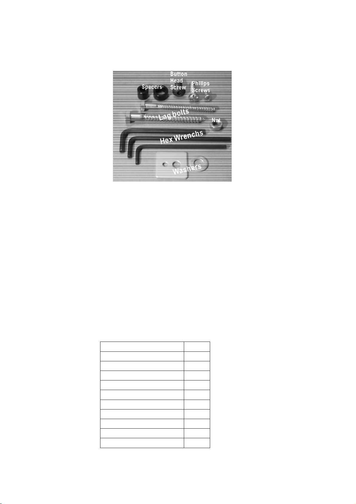
Illustration for hardware kit
LP-80 Flat Panel Cantilever Mount Installation Instructions
z 80 lb. Maximum weight capacity
z VESA 75/100 compliant
z Cantilever arm mount for large LCD and small plasma panels
z Allows maximum flexibility for installing and viewing displays.
z Cantilever arm provides full extension and 180¡of lateral rotation for viewing from multiple
locations.
z Nesting arm design allows display to be folded parallel to wall
z Provides full tilt and swivel capabilities for optimum viewing
z Durable grey or black powder coat finish
z Single stud mounting
Check the Hare Ware Kit after open the package
Description Quantity
3/16 inch Hex Wrench 1
5/32 inch Hex Wrench 1
7/32 inch Hex Wrench 1
5/16 x 3-1/2 inch Lag bolt 2
Philips Screw M5 x 8 mm 4
Philips Screw M5 x 12 mm 4
Philips Screw M4 x 8 mm 4
Philips Screw M4 x 12 mm 4
5/16 Washer 4
Button Head Screw 1/2-20 x 1/2 4
Read through the entire instruction manual before beginning.
Page 3
This flat panel cantilever will hold larger LCD monitor 30 inches and over. It will also hold smaller
plasma monitors up to 32 inches.
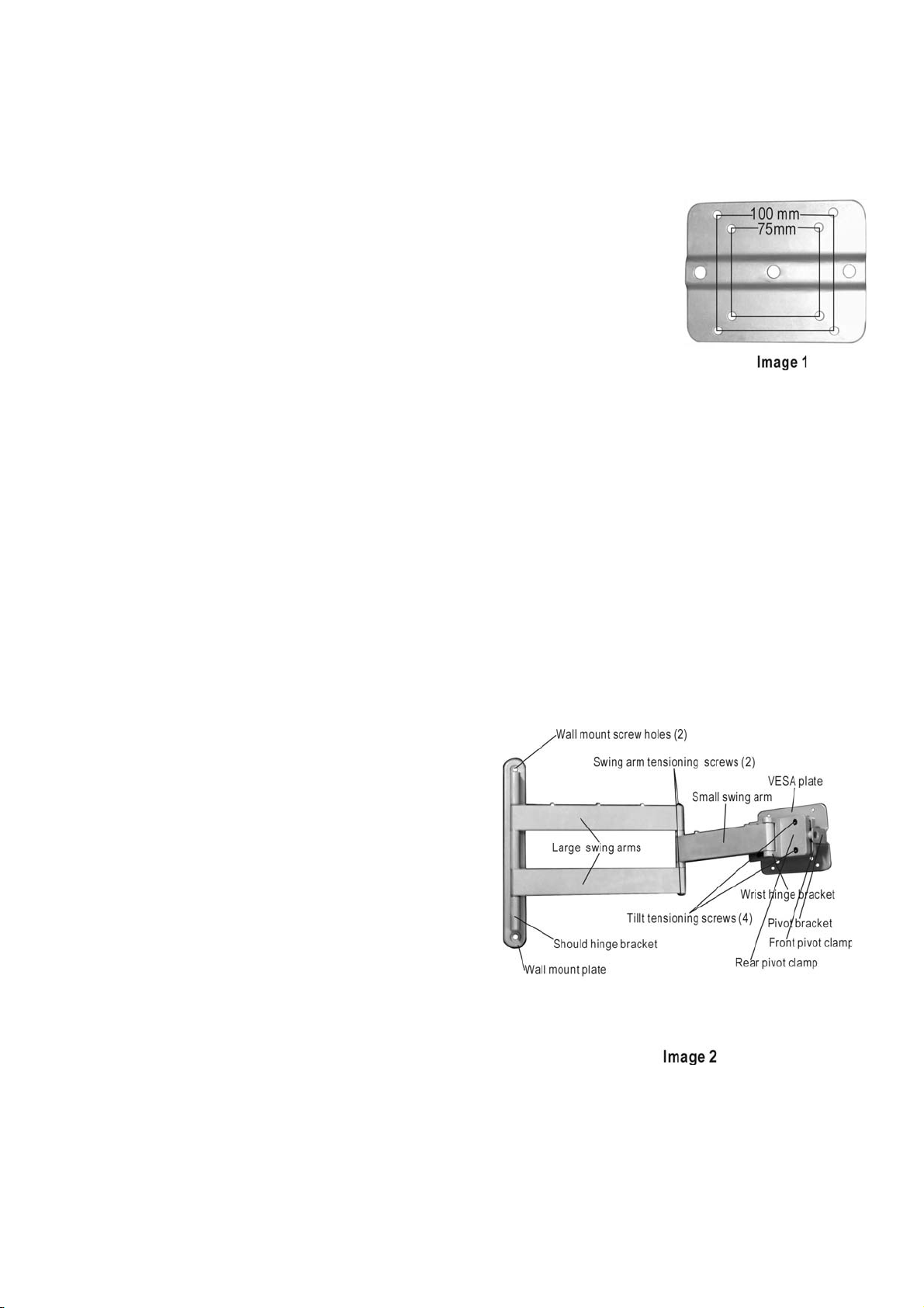
First determine if your monitor is VESA standard compliant, refer to the monitor’s
users manual. VESA is a standard mounting hole pattern (see image 1). The LP-80
Flat Panel Cantilever can attach directly to both 75mm & 100mm VESA square hole
patterns. If your monitor is not VESA standard compliant, a mounting adapter bracket
will be needed between your monitor and the cantilever mount. Contact your dealer or
contact DCS Mount to find out if an adapter is available for your monitor. All plasma
will require an adapter bracket. You will need someone to help with this installation.
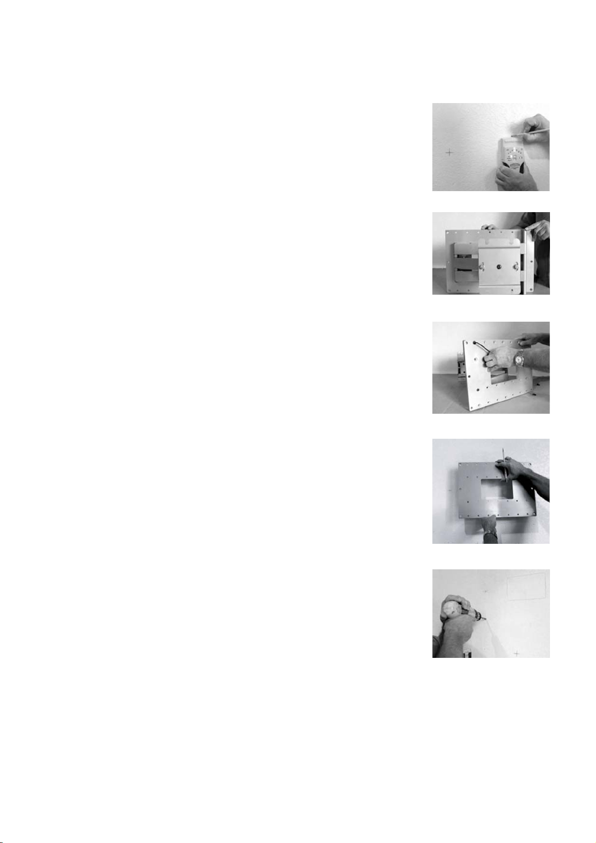
1. Determine your preferred mounting location keeping in mind good viewing angles and that this
mount MUST BE PROPERLY SECURED TO THE CENTER OF A STUD.
2. While holding the mount in place and being sure that the mount is plumb, mark the mounting
location (you can use the supplied lag bolts to poke marks into the mounting surface through the
center of each mounting hole on the wall mounting plate). When mounting to a wood stud, drill a
3-1/4 inch deep pilot hole with a 9/32”drill bit through each mark. Attach the cantilever mount to the
wall before attaching your monitor to the cantilever’s monitor mounting plate.
3. If your monitor has a table stand attached, you will need to remove the stand before attaching it to
the cantilever mount; refer to the monitor’s users manual for proper instruction to remove the stand.
In the hardware kit, there are 4 sets of screws with 4 screws per set supplied. Depending on your
monitor’s manufacture’s specifications, determine
the proper diameter & length of screws that you will
need. CAUTION: Damage to your monitor’s
internal components can occur if you use screws
that are too long. Attach your monitor to the
VESA plate using the proper screws, DO NOT over
tighten the screws that attaché to the monitor,
DAMAGE to the monitor may occur. If your
monitor needs an adapter bracket, use the supplied
1/4-20 screws to attaché the bracket, once it has
been mounted to your monitor, to the 100mm
pattern on the VESA plate.
4. If you attach any wires along the cantilever’s swing
arms (for example using P-CLIPS), be sure that the wires (or P-clips) are not pulled, pinched or
kinked between the swing arms when you move the cantilever mount around into different
positions.
Page 4
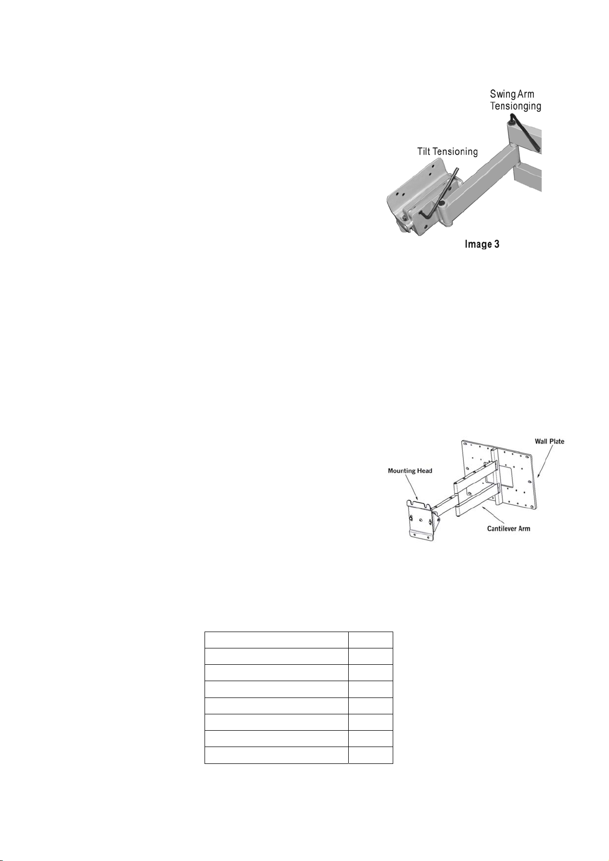
5. All of the screws are properly torqued to specification when the
unit is assembled at the factory and should not need an further
initial adjustments. However, due to the variety in size of different
monitors, MINOR adjustment may be required to optimize the
tension needed for ease of movement. Be sure that your
monitor is supported properly while making ANY changes to
the cantilever. To loosen or tighten the 4 screws respectfully on
the back of the rear pivot clamp until the desired tension is
obtained (see image 2 – Tilt Tensioning Screws and Image 3 –
Tensioning Tilt). It is important to try to maintain even torque on
each of the 4 screws. It does not take that much change in torque to make a large difference in the
tilt tension. To loosen or tighten the swing arm tension use the supplied 5/32 inch hex wrench to
loosen or tighten the screw shown in image 2 & 3 (Swing Arm Tensioning Screw). Periodic
adjustment of these screws may be necessary to maintain desired tension. There should be NO
reason to tighten or loosen the wrist hinge bracket. You should need to tighten or loosen the
shoulder hinges screws (located top and bottom of hinge), improper tightening of these screws can
damage the shoulder hinge bracket and the wall mount plate.
P-150 Cantilever Mount Installation Instructions
z 125 lb maximum weight capacity
z Cantilever arm mount for large plasma panels
z Allows maximum flexibility for installing and viewing
displays
z Horizontal leveling adjustment (20erange,f10)
z Cantilever arm provides full extension and 180e
of lateral rotation for viewing from multiple locations.
z Nesting arm design allows display to be folded parallel to
wall
z Provides full tilt and swivel capabilities for optimum viewing
z Quick mount capability with Plad PA-4260
z Durable grey or black powder coat finish.
Check the Hare Ware Kit after open the package
Description Quantity
3/16 inch Hex Wrench 1
5/32 inch Hex Wrench 1
7/32 inch Hex Wrench 1
3/8 x 3-1/2 inch Lag bolt 6
3/8ID x 13/16OD Washer 6
Button Head Screw 3/8-16 x 1/2 4
Nylon jam nut 3/8-16 4
Read through the entire instruction manual before beginning.
Page 5
Mounting the Wall Plate
Mounting to Wooden Stud
1. Determine the location where you want the display mounted on the wall.
2. USE stud finder to locate and mark the center of the two studs.
3. Remove P-150 from box. Remove the PA-4260 Adaptor plate from the
Mounting Head, and set the four 3/8-16 button head screws aside for later.
4. Remove the cantilever arm from Wall Plate
5. Align center mounting holes of wall plate with center marks on studs. Using
the wall plate as a template, mark the mounting holes and center J box hole.
Install J box as required.
Note: Electrical outlets should only be installed by a qualified electrician.
6. Drill mounting holes with 9/32 inch bit. Mounting holes should be 3 inch
(76mm) deep.
Mounting to Masonry
1. Using the wall plate as a template, mark the mounting holes in the desired
mounting location.
2. Drill mounting holes with 3/8”(10mm) masonry bit. Mounting holes should be
a minimum of 2-9/16”(65mm) deep.
3. Insert masonry mounting anchors (not supplied) into holes, and tap flash with hammer.
Proceed to Mounting Cantilever Assembly
Page 6
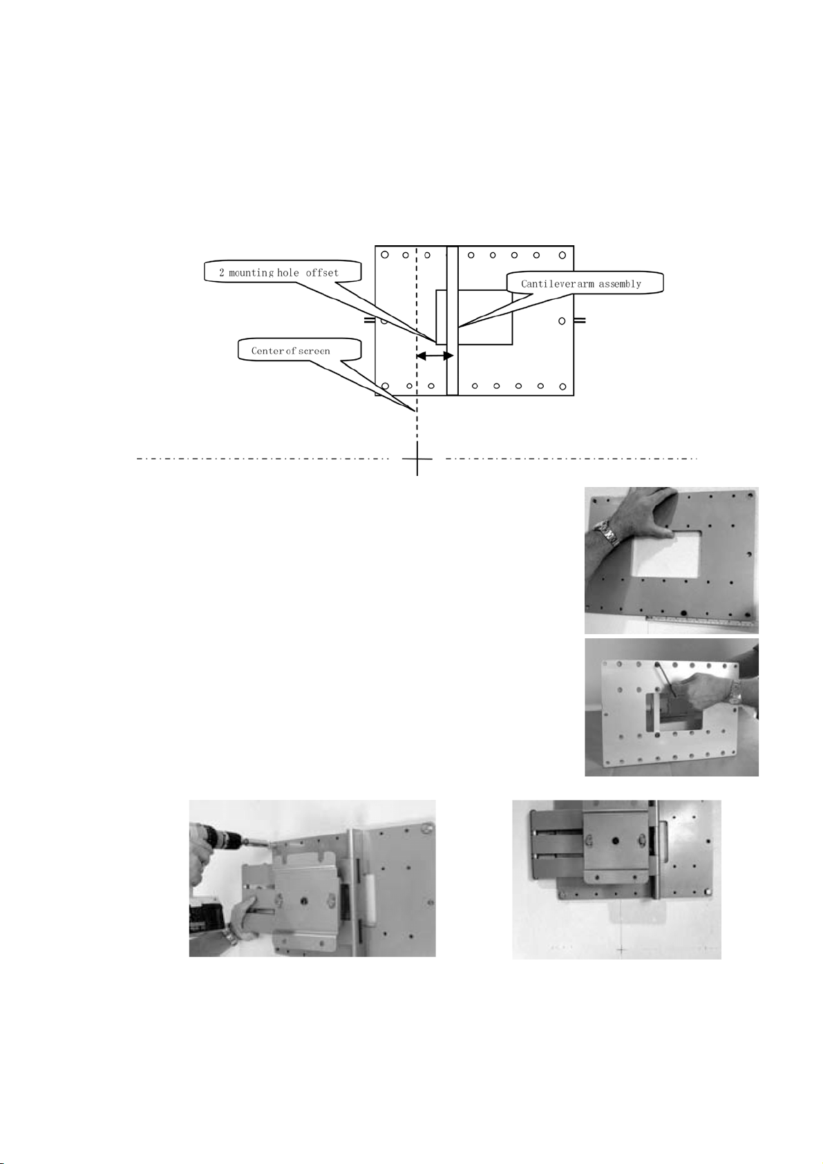
Mounting Cantilever Assembly
1. Important: for the display to be centered over the wall plate when the cantilever arm is folded, the
arm will need to be offset by approximately 4”(10.1cm) from the desired center position of the
screen. To do this, first not where the desired center of screen position intersects the wall plate, and
then mark the all plate.
2. Attach cantilever arm to the wall plate at the indicated offset location.
3. Mount cantilever assembly to wall using supplied 3/8” lag bolts.
4. Fold cantilever arm to verify center location of mounting head.
Note: the mounting head will be centered with the arm folded in one direction
only.
Page 7

Configuring the PA-4260 adaptor plate (Installation instructions)
PA-4260 Universal Plasma TV Adaptor Installation Instructions
z Fully adjustable design fits most large flat panel displays
z Includes complete hardware kit
z Quick mount capability with P-150
z Durable grey or black powder coat finish
Check the Hare Ware Kit after open the package
ID* Description Quantity
N/A Button Head Screw 1/4-20 x 1/2 14
N/A Washer 1/4 ID X 1/2 OD 4
N/A Nylon jam nut 2/4-20 4
A Button Head Screw 1/4-20 x 1/2 8
B Square Washer 8
C Spacer (0.3ID) 9/16 x 1/2 Length 8
D Spacer 3/4OD x 3/8 Length 8
E Spacer (0.42 ID) 5/8 x 1 Length 8
F 5/32 Hex Wrench (Allen) 1
G Philips Screw M4 x 16 mm 8
H Philips Screw M4 x 25 mm 6
I Philips Screw M4 x 45 mm 8
J Philips Screw M5 x 15 mm 8
K Philips Screw M5 x 45 mm 8
L Philips Screw M6 x 16 mm 8
M Philips Screw M8 x 16 mm 6
N Philips Screw M8 x 1.25 x 20 6
O Philips Screw M8 x 25 mm 8
P Philips Screw M8 x 35 mm 6
R Philips Screw M8 x 45 mm 4
* ID in Hardware Cross Reference List: Particular set of spacers and Fasteners may required for
some Flat Screen TV need, select the right ID for your display.
Measure display
The PA-4260 Ships with a standard set of mounting rails pre-installed. These rails will fit a display where
the vertical distance between mounting lands on the display are 17 1/8” or less. If your display is larger
than this, you will need to install the large set of mounting rails, which are included with the PA-4260.
Please see Install Mounting Rails at the end of this section for details.
Page 8

Set PA-4260 width
The PA-4260 is capable of handling a wide range of landed insert
widths. Measure the horizontal distance between mounting lands
on your display, and set the width of the Mounting Rails as shown,
Standard Range: 38 1/2”(98 cm) to 15 3/4”(40 cm)
Standard Configuration
For standard range configurations, loosen the screws on the sliders
using the supplied Hex Wrench; adjust rails to desired width, and
then re-tighten screws.
Narrow Range: 15 1/2”(39 cm) to 3 1/2”(9 cm)
Narrow Configuration
For narrow range configurations, flip slider/rail assembly over (as
shown below) before inserting them into the channels.
Secure Sliders and back plate
Secure sliders with (8) button head screws. For medium and narrow displays, where the nuts on the
slider are beneath the back plate, thread button head screws through the back plate and into the slider
as shown.
Note: The outer corners of the back plate must always be secured with a screw. For wide displays,
where the nuts on the slider are positioned outside of the back plate, use Nylon jam nuts with button
head screws (supplied) to secure the back plate, as shown.
Page 9

Mount PA-4260 to Display
Hardware Selection
a. Consult the supplied Hardware Cross Reference list.
b. Select the mounting hardware for your display.
Attach PA-4260 to Display
a. Position the PA-4260 over back of display.
b. Thread mounting screws through square washers and spacers (if required), as shown.
c. Thread mounting screws through slots on side rails into landed inserts, and secure loosely.
d. With mounting screws installed, center PA-4260 on the back of the display, and then tighten all
screw securely.
CAUTION: Do not use power tools or over-tighten the mounting screws.
Install Mounting Rails
1. Remove slider retaining screws as shown.
2. Remove sliders from channels.
3. Select required side size: Medium rail- up to 17 1/8”height of
landed inserts Large rail- up to 25” height of landed inserts.
4. Attach selected side rails to sliders as shown.
5. Re-install slider assemblies into channels as shown, and return
to Set PA-4260 Width section.
Page 10

Mounting the display
1. Locate the set of four 3/8”-16 button head cap screws removed at the
beginning of the installation.
2. Thread two of the screws approximately a 1/4”(0.6cm) into the upper
set of PEM nuts on the adaptor plate, as shown
3. With the help of an assistant, carefully lift the display and hang it onto
the P-150 by dropping the exposed portion of the screws down into the
key slots on the nose piece of the P-150.
4. With the display hanging on the mount, thread the second set of screw
into place, and then tighten all four screws securely.
Display Adjustments
Roll Control
Function – Horizontal leveling of the display.
Operation – Grasp the sides of the display, and roll it into the desired position.
Adjusting Roll Tension – Roll tension is controlled by the two tension bolts located
on the outer edges of the nose piece. Use an open-ended 9/16” wrench to make
adjustments to the tension bolts by inserting wrench between the nose piece and the
adaptor plate.
Page 11

Vertical Tilt
Function – raising and lowering the screen edge to improve viewing
angle/picture quality.
Operation – Loosen tilt tension screws with supplied 3/16” Hex wrench as
shown. Adjust display for desired tilt angle. Re-tighten tension screws.
CAUTION :
It is important to try to maintain even torque on each of the 4 screws.
Swivel
Purpose – Optimize viewing angle for off center viewing positions.
Operation – Grasp edges of display and swivel into desired position.
Adjust swivel tension – Adjust tension with supplied 3/16” Hex wrench.
180¡Pan
Purpose – Allows display to be positioned perpendicular to wall.
Operation – Extend cantilever arm completely. Fully swivel display in desired
direction.
Note: Maximum screen size for full 180¡Pan is approximately 50.
Stowing the screen
Purpose – Allows display to be folded flat to the wall.
Operation – Grasp center pivot point of cantilever arm and edge of display. Fold arm
in half at pivot point and push display back flat against wall.
Centering the Screen
The screen will be centered with the cantilever arm folded in one direction only, as
shown.
Page 12

HARDWARE CROSS REFERENCE LIST
3DJH
Manufacturer Model Spacer Part ID
AKIRA EPM 420A/B NONE N/A 5mm x 15 J
AKIRA EPM 600 NONE N/A 8mm x 20* N
AKAI PDP4290 NONE N/A M8 x 35 P
B & Q BEOVISION 4 3/4 x 3/8 D 8mm x 35 P
BENQ PDP46W1 NONE N/A 6mm x 35 L
DAWOO DP425M NONE N/A 5mm x 15 J
DAWOO DSP4210 NONE N/A 5mm x 15 J
DWIN HD-501 3/4 x 3/8 D 8mm x 35 P
DWIN HD-50TS 3/4 x 3/8 D 8mm x 35 P
ELECTROGRAPH DTS42DD 3/4 x 3/8 D 8mm x 35 P
ELECTROGRAPH DTS4230 NONE N/A 5mm x 15 J
FAROUDJA FDP-42HD10 NONE N/A 5mm x 15 J
FAROUDJA FDP-50HD10 NONE N/A 5mm x 15 J
Fastener
dia x length
Part ID
FUJITSU P42HHA10WS 3/4 x 3/8 D 8mm x 35 P
FUJITSU P42VCA21 NONE N/A 8mm x 20 N
FUJITSU P42HCA11 NONE N/A 8mm x 20 N
FUJITSU P50XCA11UH NONE N/A 8mm x 20 N
FUJITSU PDS-4207 NONE N/A 8mm x 20 N
FUJITSU PDS-4233 NONE N/A 8mm x 20 N
FUJITSU PDS-5002 NONE N/A 8mm x 20 N
FUJITSU PDS-5003 NONE N/A 8mm x 20 N
FUJITSU PDS-5004 NONE N/A 8mm x 20 N
FUJITSU PDS-6101 NONE N/A 8mm x 20 N
FUJITSU PDS4208W NONE N/A 8mm x 20 N
FUJITSU PDS-4209 NONE N/A 8mm x 20 N
FUJITSU PDS-4210 NONE N/A 8mm x 20 N
FUJITSU PDS-4211 NONE N/A 8mm x 20 N
FUJITSU PDS-4212 NONE N/A 8mm x 20 N
FUJITSU PDS-4213 NONE N/A 8mm x 20 N
FUJITSU PDS-4214 NONE N/A 8mm x 20 N
FUJITSU PDS-4221 NONE N/A 8mm x 20 N
FUJITSU PDS-4222 NONE N/A 8mm x 20 N
FUJITSU PDS-4233 NONE N/A 8mm x 20 N
DCS Mount
Page 13

HARDWARE CROSS REFERENCE LIST
3DJH
Manufacturer Model Spacer Part ID
HITACHI 50HDT50 NONE N/A 6mm x 16 L
HITACHI 50HDT55 NONE N/A 6mm x 16 L
HITACHI CMP4201 NONE N/A 6mm x 16 L
HITACHI CMP4202 NONE N/A 6mm x 16 L
HITACHI CMP5000WXV NONE N/A 6mm x 16 L
HITACHI 32HDT20 NONE N/A 6mm x 16 L
HITACHI 42HDT20 NONE N/A 6mm x 16 L
HITACHI 42HDT50 NONE N/A 6mm x 16 L
HITACHI 50HDT50 NONE N/A 6mm x 16 L
JVC GM-P42UG NONE N/A 5mm x 15 J
JVC PD-42WX84 NONE N/A 5mm x 15 J
JVC PD-42WV74 NONE N/A 5mm x 15 J
MARANTZ PD-4293D NONE N/A 5mm x 15 J
MARANTZ PD-5020 NONE N/A 5mm x 15 J
MARANTZ PD-6120D
DO NOT CANTILEVER
Fastener
dia x length
Part ID
MITSUBISHI PD4220 NONE N/A 5mm x 15 J
MITSUBISHI PD4230 NONE N/A 5mm x 15 J
MITSUBISHI PD5020 NONE N/A 5mm x 15 J
MITSUBISHI PD5030 NONE N/A 5mm x 15 J
MITSUBISHI PD6120 NONE N/A 5mm x 15 J
MITSUBISHI PD6130 NONE N/A 5mm x 15 J
MITSUBISHI PD5010 NONE N/A 5mm x 15 J
MONOVISION PD46ACS NONE N/A 5mm x 15 J
MYRON & DAVIS AP-42 3/4 x 3/8 d 8mm x 35 P
NEC 42HP82 5/8 x1 E 5mm x 45 K
NEC PX-42MP1 5/8 x1 E 5mm x 45 K
NEC PX-42MP2 5/8 x1 E 5mm x 45 K
NEC PX-42MP3 5/8 x1 E 5mm x 45 K
NEC PX-42VP2A 5/8 x1 E 5mm x 45 K
NEC PX-50M5A 5/8 x1 E 5mm x 45 K
NEC PX50-MP1 5/8 x1 E 5mm x 45 K
NEC PX-50PD1 5/8 x1 E 5mm x 45 K
NEC PX-50VP1A 5/8 x1 E 5mm x 45 K
NEC PX-50XM1A 5/8 x1 E 5mm x 45 K
DCS Mount
Page 14

HARDWARE CROSS REFERENCE LIST
3DJH
Manufacturer Model Spacer Part ID
NEC 42MP3 NONE N/A 5mm x 15 J
NEC 42MP4 NONE N/A 5mm x 15 J
NEC 42VP4A NONE N/A 5mm x 15 J
NEC 42VP4D NONE N/A 5mm x 15 J
NEC 50XM3A NONE N/A 5mm x 15 J
NEC 50MP2 NONE N/A 5mm x 15 J
NEC 61MP1 5mm x 15 J
NEC PD-42XM1 NONE N/A 5mm x 15 J
NEC PX-61M1A 5mm x 15 J
PANASONIC PT-37PD4 3/4 x 3/8 D 8mm x 35 P
PANASONIC PT-42PD1-P 3/4 x 3/8 D 8mm x 35 P
PANASONIC PT-42PD2-P 3/4 x 3/8 D 8mm x 35 P
PANASONIC PT-42PD3-P 3/4 x 3/8 D 8mm x 35 P
PANASONIC PT42D4P 3/4 x 3/8 D 8mm x 35 P
PANASONIC PT-42PHD4 3/4 x 3/8 D 8mm x 35 P
PANASONIC TH-42PWD3 NONE N/A 8mm x 45* R
PANASONIC TH42PA20U NONE N/A 8mm x 45* R
PANASONIC TH42PX20U NONE N/A 8mm x 45* R
PANASONIC TH-42PWD3U NONE N/A 8mm x 45* R
PANASONIC PT-50PD3-P 3/4 x 3/8 D 8mm x 35 P
PANASONIC PT-50PHD4 3/4 x 3/8 D 8mm x 35 P
PANASONIC TH50PHD3U NONE N/A 8mm x 45* R
PANASONIC 50PHW5U2 3/4 x 3/8 D 8mm x 35 P
PANASONIC FP42HD3P 3/4 x 3/8 D 8mm x 35 P
PANASONIC FP50HD3P 3/4 x 3/8 D 8mm x 35 P
PANASONIC FP42HDX63 3/4 x 3/8 D 8mm x 35 P
PANASONIC FP50HDX63 3/4 x 3/8 D 8mm x 35 P
PANASONIC PT-37A20UP 3/4 x 3/8 D 8mm x 35 P
PANASONIC PT-42PD4-P 3/4 x 3/8 D 8mm x 35 P
PANASONIC PT-42PA20UP 3/4 x 3/8 D 8mm x 35 P
PANASONIC PT-42PX20UP 3/4 x 3/8 D 8mm x 35 P
DO NOT CANTILEVER
DO NOT CANTILEVER
Fastener
dia x length
Part ID
PHILIPS 32PF9954 NONE N/A 5mm x 15 J
PHILIPS 42FD9954 NONE N/A 5mm x 15 J
PHILIPS 42PF9954 NONE N/A 5mm x 15 J
PHILIPS 50FD9934 NONE N/A 5mm x 15 J
PHILIPS 50FD9955 NONE N/A 5mm x 15 J
PHILIPS 50PF9955 NONE N/A 5mm x 15 J
DCS Mount
Page 15

HARDWARE CROSS REFERENCE LIST
3DJH
Manufacturer Model Spacer Part ID
PIONEER PRO800 NONE N/A 8mm x 20* N
PIONEER PDP-433CMX NONE N/A 8mm x 20* N
PIONEER PDP-4330HD NONE N/A 8mm x 20* N
PIONEER PRO1000 NONE N/A 8mm x 20* N
PIONEER PDP-502MX NONE N/A 8mm x 20* N
PIONEER PDP-5030HD NONE N/A 8mm x 20* N
PIONEER PDP-4340HD NONE N/A 8mm x 20* N
PIONEER PDP-503CMX NONE N/A 8mm x 20* N
PIONEER PDP-503MX NONE N/A 8mm x 20* N
PIONEER PDP-610CMX 8mm x 20* N
PIONEER PDP-V402 NONE N/A 8mm x 20* N
RCA PHD50400 NONE N/A 5mm x 15 J
RCA PHD50500 NONE N/A 5mm x 15 J
RUNCO PL-42CX 3/4 x 3/8 D 8mm x 35 P
RUNCO CW42 NONE N/A 5mm x 15 J
RUNCO PL-43HDX NONE N/A 8mm x 20 N
RUNCO PL-50CX 3/4 x 3/8 D 8mm x 35 P
RUNCO PL-50HDX NONE N/A 8mm x 20 N
RUNCO CW50 NONE N/A 5mm x 15 J
RUNCO CW61 5mm x 15 J
RUNCO PL-61CX 5mm x 15 J
RUNCO PL-61HDX NONE N/A 5mm x 15 J
DO NOT CANTILEVER
DO NOT CANTILEVER
DO NOT CANTILEVER
Fastener
dia x length
Part ID
SAMPO PME-42S6 3/4 x 3/8 D 8mm x 35 P
SAMPO PME-42X6 3/4 x 3/8 D 8mm x 35 P
SAMPO PME-42V3 3/4 x 3/8 D 8mm x 35 P
SAMSUNG PPM4252 3/4 x 3/8 D 8mm x 35 P
SAMSUNG SPN4235 3/4 x 3/8 D 8mm x 35 P
SAMSUNG SPL4225K 3/4 x 3/8 D 8mm x 35 P
SAMSUNG HPL5025K 3/4 x 3/8 D 8mm x 35 P
SAMSUNG HPN5039 3/4 x 3/8 D 8mm x 35 P
SAMSUNG SPD-50P2HM 3/4 x 3/8 D 8mm x 35 P
SAMSUNG SPD-63P1HM 3/4 x 3/8 D 8mm x 35 P
SAMSUNG PPM63HI 3/4 x 3/8 D 8mm x 25 O
SAMSUNG HPN5027 3/4 x 3/8 D 8mm x 35 P
SAMSUNG HPN5039 3/4 x 3/8 D 8mm x 35 P
DCS Mount
Page 16

HARDWARE CROSS REFERENCE LIST
3DJH
Manufacturer Model Spacer Part ID
SAMSUNG HPN6339 3/4 x 3/8 D 8mm x 35 P
SAMSUNG HPM6315 8mm x 35 P
SAMSUNG PPM42S3 3/4 x 3/8 D 8mm x 35 P
SAMSUNG PPM50H3 3/4 x 3/8 D 8mm x 35 P
SAMSUNG PPM63H3 8mm x 35 P
SAMSUNG SPL-4225K 3/4 x 3/8 D 8mm x 35 P
SAMSUNG SPN-4235 3/4 x 3/8 D 8mm x 35 P
SAMSUNG SPM-4227 3/4 x 3/8 D 8mm x 35 P
SHARP PZ-43HV2U NONE N/A 8mm x 20 N
SHARP PZ-50HV2U NONE N/A 8mm x 20 N
SONY KDE42XBR950 NONE N/A 4mm x 16 G
SONY KDE50XBR950 NONE N/A 4mm x 16 G
SONY KDE61XBR950 4mm x 16 G
SONY KE32TS2 9/16 x 1/2 C 4mm x 25 H
SONY KE42TS2 9/16 x 1/2 C 5mm x 15 J
SONY KE37XS910 NONE N/A 5mm x 15 J
SONY KE42XS910 NONE N/A 5mm x 15 J
SONY KE42XBR900 NONE N/A 5mm x 15 J
SONY KE42XBR910 NONE N/A 4mm x 16 G
SONY KE42XBR950 NONE N/A 4mm x 16 G
SONY KE50XBR900 NONE N/A 5mm x 15 J
SONY KE50XBR910 NONE N/A 4mm x 16 G
SONY KE50XBR950 NONE N/A 4mm x 16 G
SONY KLV30XBR900 NONE N/A 4mm x 16 G
SONY KZ-32TS1 9/16 x 1/2 C 4mm x 25 H
SONY KZ-42TS1 5/8 x 1 E 4mm x 45 I
SONY PFM-32CI NONE N/A 4mm x 16 G
SONY PFM-42B1 NONE N/A 8mm x 16 M
SONY PFM-42B2 NONE N/A 8mm x 16 M
SONY PFM-50C1 NONE N/A 8mm x 16 M
SONY PFM-500A2WU NONE N/A 8mm x 16 M
SONY PFM-510A2WU NONE N/A 8mm x 16 M
DO NOT CANTILEVER
DO NOT CANTILEVER
DO NOT CANTILEVER
Fastener
dia x length
Part ID
TOSHIBA 42HP82 NONE N/A 5mm x 15 J
TOSHIBA 50HP82 NONE N/A 5mm x 15 J
TOSHIBA 42HP83 NONE N/A 5mm x 15 J
DCS Mount
Page 17

HARDWARE CROSS REFERENCE LIST
3DJH
Manufacturer Model Spacer Part ID
YAMAHA PDM-1 3/4 x 3/8 D 8mm x 35 P
ZENITH P40B24 NONE N/A 5mm x 15 J
ZENITH P42W22B NONE N/A 5mm x 15 J
ZENITH P42W26 NONE N/A 5mm x 15 J
ZENITH P42W22BH NONE N/A 5mm x 15 J
ZENITH P60W26 NONE N/A 8mm x 20 N
ZENITH P60W26H 8mm x 20 N
ZENITH DPDP60W 8mm x 16 M
ZENITH P40V22 NONE N/A 5mm x 15 J
ZENITH P40V24 NONE N/A 5mm x 15 J
ZENITH P42W22B/H NONE N/A 5mm x 15 J
ZENITH P42W24B/P NONE N/A 5mm x 15 J
ZENITH P42W34/34H NONE N/A 5mm x 15 J
ZENITH P42W38 NONE N/A 5mm x 15 J
ZENITH P50W26B NONE N/A 5mm x 15 J
ZENITH P50W28B/P NONE N/A 5mm x 15 J
ZENITH P50W38/38H NONE N/A 5mm x 15 J
ZENITH P60W26P 8mm x 20 N
ZENITH P60W38/38H 8mm x 20 N
DO NOT CANTILEVER
DO NOT CANTILEVER
DO NOT CANTILEVER
DO NOT CANTILEVER
Fastener
dia x length
Part ID
* may substitute a 8 mm x 60
mm, using a 3/4 x 3/8 spacer
If your Flat Screen TV is not on this list please cantact DCS Mount for updated
information.
*DCS Mount
is not resposible for changes or errors in manufacturer's
specifucations.
DCS Mount
 Loading...