


Dcs Edv36-bqarn, Edv36-bqar, Edv36-bqa, Edv36-bqan, Edv27-bqrn Owner's Manual
...
ENDEAVOR GRILL
Use and Care Guide
Installation Guide
Models:
■
EDV27-BQ
■
EDV27-BQR
■
EDV36-BQA
■
EDV36-BQAR
1
Thank you for selecting this Professional “ENDEAVOR” Series Grills. Because of these appliances’ unique
features we have developed this Use and Care Guide and Installation Guide. It contains valuable information
on how to properly operate and maintain your new appliance for years of safe and enjoyable cooking.
To help serve you better, please fill out and return the Ownership Registration Card and keep this guide
handy, as it will help answer questions that may arise as you use your new appliance.
For your convenience, product questions can be answered by a
Consumer Service Representative at 877-553-0243.
WARNING
Improper installation, adjustment alteration, service or maintenance can cause property
damage, injury or death. Read the installation, operating and maintenance instructions
thoroughly before use, installing or servicing this equipment. For outdoor use only.
PRECAUTION
Do Not store or use gasoline or any other flammable vapors and liquids in the vicinity of this or
any other appliance.
FOR YOUR SAFETY
If you smell gas:
1. Shut-off gas to the appliance.
2. Extinguish any open flames.
3. If odor continues, immediately call your gas supplier.
WARNING
A separate regulator must be installed at the appliance. A regulator is supplied with this
product.
PLEASE RETAIN THIS MANUAL
FOR FUTURE REFERENCE.
A Message To Our Customers

2
SAFETY PRACTICES & PRECAUTIONS......................................................3-4
GRILL MODELS .......................................................................................................5
GAS REQUIREMENTS........................................................................................6-7
LOCATING GRILL/BUILT-IN CLEARANCES...............................................8-9
BUILT-IN CONSTRUCTION DETAILS........................................................10-11
LEAK TESTING.......................................................................................................12
INSTALLER FINAL CHECKLIST .......................................................................13
BURNER ADJUSTMENTS.............................................................................13-14
USING THE GRILL...........................................................................................15-16
LIGHTING INSTRUCTIONS ..........................................................................16-17
USING THE ROTISSERIE .............................................................................18-19
CARE & CLEANING ..............................................................................................20
BURNER REMOVAL AND CLEANING ...........................................................21
TROUBLESHOOTING ..........................................................................................22
PARTS LISTS
Grill Burner Assembly 27” Parts List................................................................23
Grill Body 27” Parts List...................................................................................24
Rotisserie Assembly 27” Parts List..................................................................25
Grill Burner Assembly 36” Parts List................................................................26
Grill Body 36” Parts List...................................................................................27
Rotisserie Assembly 36” Parts List..................................................................28
Cart Assembly 27” and 36” Parts List .............................................................29
HEAD AND CART ASSEMBLY ..........................................................................30
WIRING DIAGRAM
Wiring Diagram for EDV27-BQ.........................................................................31
Wiring Diagram for EDV27-BQR ......................................................................32
Wiring Diagram for EDV36-BQA ......................................................................33
Wiring Diagram for EDV36-BQAR....................................................................34
SERVICE ...................................................................................................................35
WARRANTY .............................................................................................................36
Ta b le Of Contents
3
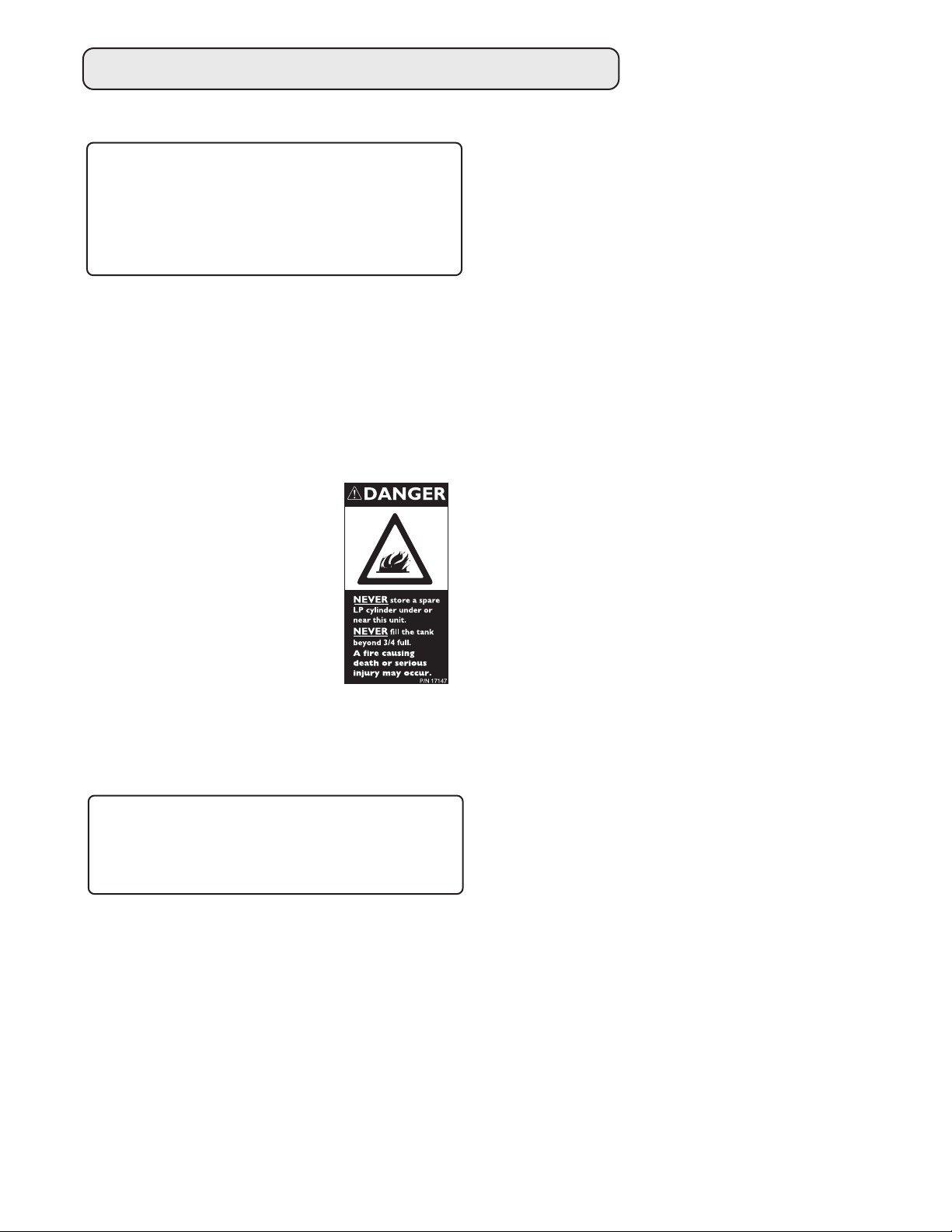
IMPORTANT SAFETY NOTICE:
Certain Liquid Propane dealers may fill
liquid propane cylinders for use in the
grill beyond cylinder filling capacity.
This “Overfilling” may create a
dangerous condition.
• “Overfilled” tanks can build up excess pressure.
As a safety device, the tanks pressure relief valve
will vent propane gas vapor to relieve this excess
pressure. This vapor is combustible and
therefore can be ignited. To reduce this danger,
you should take the following safety precautions:
1. When you have your tank filled, be sure you
tell the supplier to fill it to no more than 3/4
(75%) of its total capacity.
2. If you own or use an extra
spare tank, or have a
disconnected tank, you
should NEVER store it near
or under the grill unit or
heat box, or near any other
ignition or heat source. A
metallic sticker with this
warning is attached to the
grill to remind you, your
family and all others who
may use your BBQ grill of these safety
precautions.
Do not remove this sticker.
WARNING: Do not try lighting
this appliance without reading the
“LIGHTING INSTRUCTIONS” section
of this manual.
• This Grill is for outdoor use only.
• Children should not be left alone or unattended in
an area where the grill is being used. Never allow
them to sit, stand or play on or around the grill at
any time. When in use, portions of the grill get
hot enough to cause severe burns.
• Do not store items of interest to children around
or below the grill, in the cart or masonry
enclosure. Never allow children to crawl inside a
cart or enclosure.
• Never let clothing, pot holders or other
flammable materials come in contact with or too
close to any grate, burner or hot surface until it
has cooled. Fabric may ignite and result in
personal injury.
• Do not heat unopened food containers as a
build-up of pressure may cause the container to
burst.
• Use a covered hand when opening the grill lid
and only do so slowly to allow heat and steam
to escape.
• Never lean over an open grill. When lighting a
burner, always pay close attention to what you
are doing. Be certain you are turning the knob
labeled for the burner you intend on using.
• When using the grill, do not touch the grill rack,
burner grate or immediate surrounding area as
these areas become extremely hot and could
cause burns.
• Grease is flammable. Let hot grease cool before
attempting to handle it. Avoid letting grease
deposits collect in the drip pan. Clean often.
• Do not use aluminum foil to line drip pans or grill
racks. This can severely upset combustion air
flow or trap excessive heat in the control area.
The result of this can be melted knobs or
ignition module.
• Begin by insuring proper installation and
servicing. Follow the installation instructions.
Have your grill installed by a qualified
technician. Have the installer show you where
the gas supply shut-off valve is located so that
you know where to shut-off the gas to the grill.
If you smell gas, your installer has not done a
proper job of checking for leaks. If the
connections are not perfectly seated and
tightened, you can have a small leak and
therefore a faint gas smell. Finding a leak is not
a “do-it-yourself” procedure. Some leaks can
only be found with the burner control in the “on”
position and this must be done by a qualified
technician.
Safety Practices & Precautions

4
For personal safety, wear proper apparel. Loose
fitting garments or sleeves should never be worn
while using this appliance. Some synthetic fabrics
are highly flammable and should not be worn while
cooking. Only certain types of glass, heat-proof
glass ceramic, earthenware, or other glazed
utensils are suitable for grill use. Use of these
types of materials may break with sudden
temperature changes. Use only on low or medium
heat settings according to the manufacturer’s
directions.
WARNING: Spiders and insects can
nest in the burners of this and any
other grill, and cause the gas to flow
from the front of the burner. This is a
very dangerous condition which can
cause a fire to occur behind the valve
panel, thereby damaging the grill and
making it unsafe to operate.
• Clean the grill with caution. Avoid steam burns;
do not use a wet sponge or cloth to clean the
grill while it is hot. Some cleaners produce
noxious fumes or can ignite if applied to a hot
surface.
• Be sure all grill controls are turned off and the
grill is cool before using any type of aerosol
cleaner on or around the grill. The chemical that
produces the spraying action could, in the
presence of heat, ignite or cause metal parts to
corrode.
• Do not use the grill for cooking excessively fatty
meats or products which promote flare-ups.
• Never grill without the drip pan in place and
pushed all the way to the back of the grill.
Without it hot grease could leak downward and
produce a fire or explosion hazard.
• Do not operate the grill under unprotected
combustible construction. Use only in well
ventilated areas. Do not use in buildings,
garages, sheds, breezeway or other such
enclosed areas. This unit is for outdoor use only.
• Keep the area surrounding the grill free from
combustible materials, trash, or combustible
fluids and vapors such as gasoline or charcoal
lighter fluid. Do not obstruct the flow of
combustion and ventilation air.
• If a cart unit is stored indoors ensure that it is
cool, then push, never pull, the grill. If LP, the
cylinder must be unhooked and the LP cylinder
stored outside in a well ventilated area, out of
reach of children.
• Do not use charcoal in the grill. Never use the
grill in a windy area. Keep any electrical supply
cord, or the rotisserie motor cord away from the
heated areas of the grill.
• Never use the grill in windy conditions. If located
in a consistently windy area (oceanfront,
mountaintop, etc.) a wind break will be required.
Always adhere to the specified clearances listed.
• Never use a dented or rusty LP tank. Keep the
ventilation openings of the cylinder enclosure
free and clear from debris.
• Use only dry potholders; moist or damp
potholders on hot surfaces may cause burns
from steam. Do not use a towel or bulky cloth in
place of potholders. Do not let potholders touch
hot portions of the grill rack or burner grate.
• CALIFORNIA PROPOSITION 65-WARNING: The
Burning of gas cooking fuel generates some by
products which are on the list of substances
which are known by the State of California to
cause cancer or reproductive harm. California
law requires businesses to warn customers of
potential exposure to such substances. To
minimize exposure to these substances always
operate this unit according to the use and care
manual, ensuring you provide good ventilation
when cooking with gas.
Safety Practices & Precautions
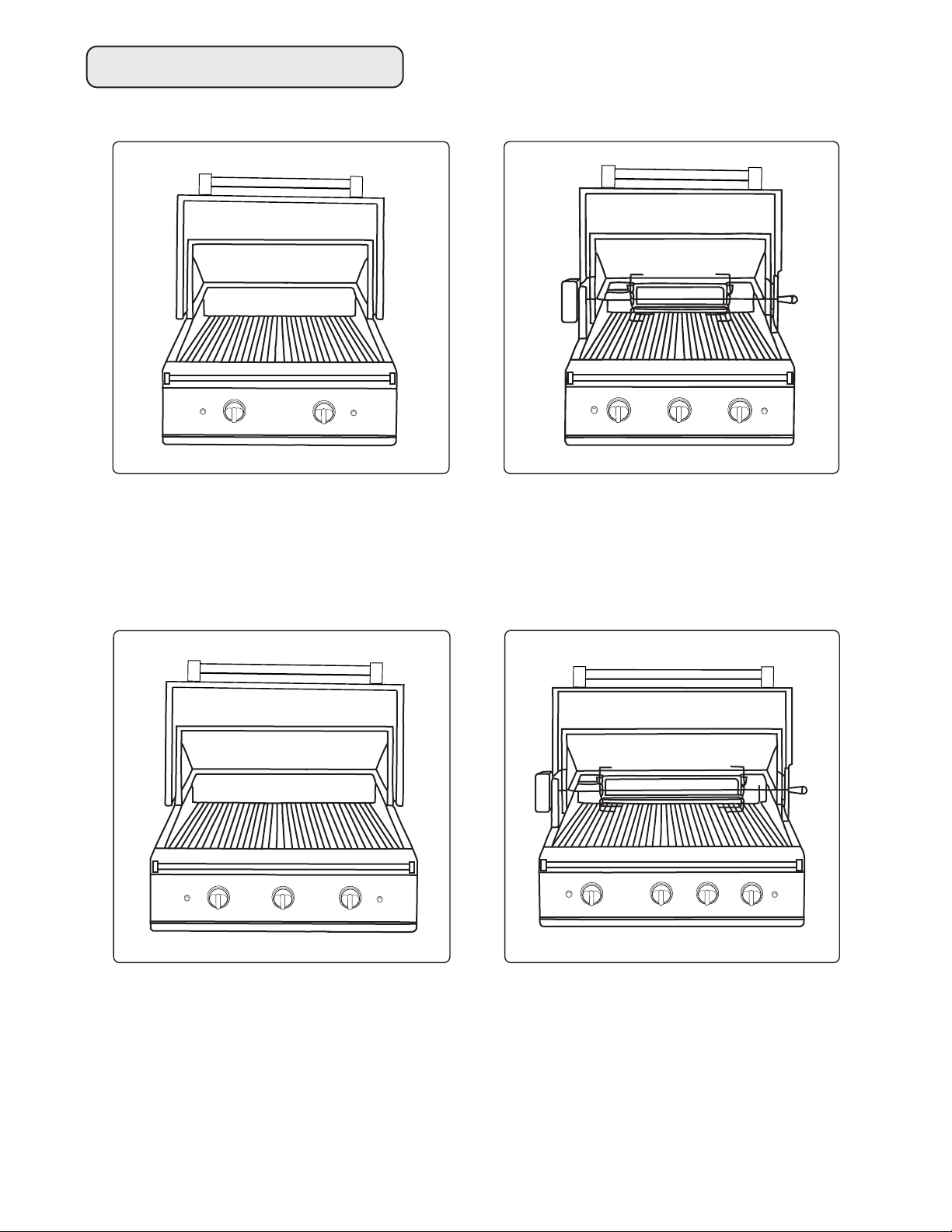
5
ROTISSERIE
GRILL
GRILL
IGNITION
SAFETY
HOLD IN 10 SEC.
WHILE LIGHTING
(ROTISSERIE)
GRILL
GRILL
SAFETY
HOLD IN 10 SEC.
WHILE LIGHTING
(ROTISSERIE)
IGNITION
EDV27-BQ
EDV27-BQR
Grill Models
ROTISSERIE
GRILL
GRILL
GRILL
IGNITION
SAFETY
HOLD IN 10 SEC.
WHILE LIGHTING
(ROTISSERIE)
GRILL
GRILL
SAFETY
HOLD IN 10 SEC.
WHILE LIGHTING
(ROTISSERIE)
IGNITION
GRILL
EDV36-BQA
EDV36-BQAR
6
Verify the type of gas supply to be used, either
natural or LP, and make sure the marking on the
appliance rating plate agrees with that of the
supply. Never connect an unregulated gas line to
the appliance.
An installer supplied gas shut-off valve must be
installed in an easily accessible location. All
installer supplied parts must conform to local
codes, or in the absence of local codes, with the
National Electrical Code, ANSI/NFPA 70-1990, and
the National Fuel Gas Code,
ANSI Z223.1-1988.
All pipe sealants must be an approved type and
resistant to the actions of LP gases. Never use
pipe sealant on flare fittings. All gas connections
should be made by a qualified technician and in
accordance with local codes and ordinances. In
the absence of local codes, the installation must
comply with the national fuel gas code
ANSI Z223.1-1988. Gas conversion kits are
available from the factory. When ordering gas
conversion kits have the model number, and the
type of gas (natural or LP) from your grill.
TOTAL GAS CONSUMPTION OF THE
GRILL WITH ALL BURNERS ON HI:
EDV27-BQR - 54,000 Btu/hr
EDV27-BQ - 40,000 Btu/hr
EDV36-BQA - 60,000 Btu/hr
EDV36-BQAR - 74,000 Btu/hr
The appliance and its individual shut-off valve must
be disconnected from the gas supply piping system
during any pressure testing of that system at test
pressures in excess of 1/2 PSIG (3.5 kPa.) The
appliance must be isolated from the gas supply
piping system by closing its individual manual shutoff valve during any pressure testing of the gas
supply piping system at test pressures equal to or
less than 1/2 PSIG (3.5 kPa.). The installation of
this appliance must conform with local codes or, in
the absence of local codes, with the national fuel
gas code, ANSI Z223.1a-1988. Installation in
Canada must be in accordance with the Standard
Can1-b149.1 and/or .2 (installation code for gas
burning appliances and equipment) and local
codes.
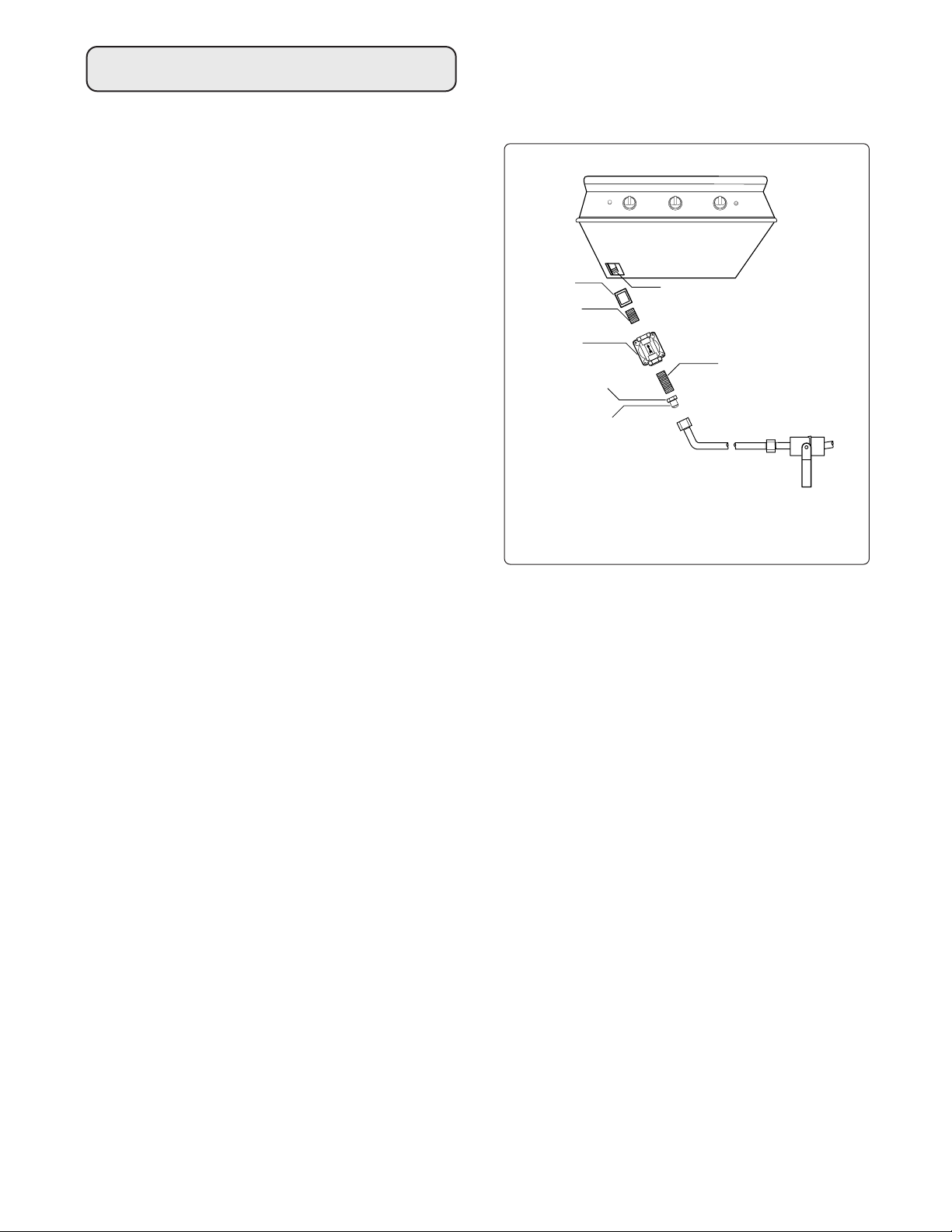
Coupling
1/2 NPT
Close
Nipple
Adapter 1/2 NPT
to 3/8 flare fitting
Do not put threading
compound on these
threads
*Installation must conform with local
codes or with the National Fuel Gas Code
ANSI Z223.1
Bottom of unit
Threading
compound must be
resistant to LP gas
1/2 NPT x 5"
Close Nipple
Bottom of unit
Installer supplied
shut-off valve must
be easily accessible*
Regulator
NATURAL GAS HOOK UP:
Connection: 1/2" NPT male with 3/8" flare
adapter. Operating pressure: 4.0" W.C.
Supply pressure: 5" to 14" water column. If in
excess of 14" W.C. a step down regulator is
required. Check with your local gas utility
company or with local codes for instructions on
installing gas supply lines. Be sure to check on
type and size of run, and how deep to bury the
line. If the gas line is too small, the grill will not
function properly. Any joint sealant used must be
an approved type and be resistive to the actions of
LP gases.
TO HOOK-UP THE FITTINGS SUPPLIED
WITH THE GRILL:
Assemble as shown (Fig.01). Use threading
compound on male threads only. Do not use
threading compound on the male end of the 1/2
NPT to 3/8 flare adapter. Use a second pipe
wrench to hold the grill inlet pipe to avoid shifting
any internal gas lines of the grill. Ensure that the
regulator arrow points in the direction of gas flow
towards the unit, away from the supply. Do not
forget to place the installer supplied gas valve in an
accessible location.
FIG.01
Natural Gas
Gas Requirements
7
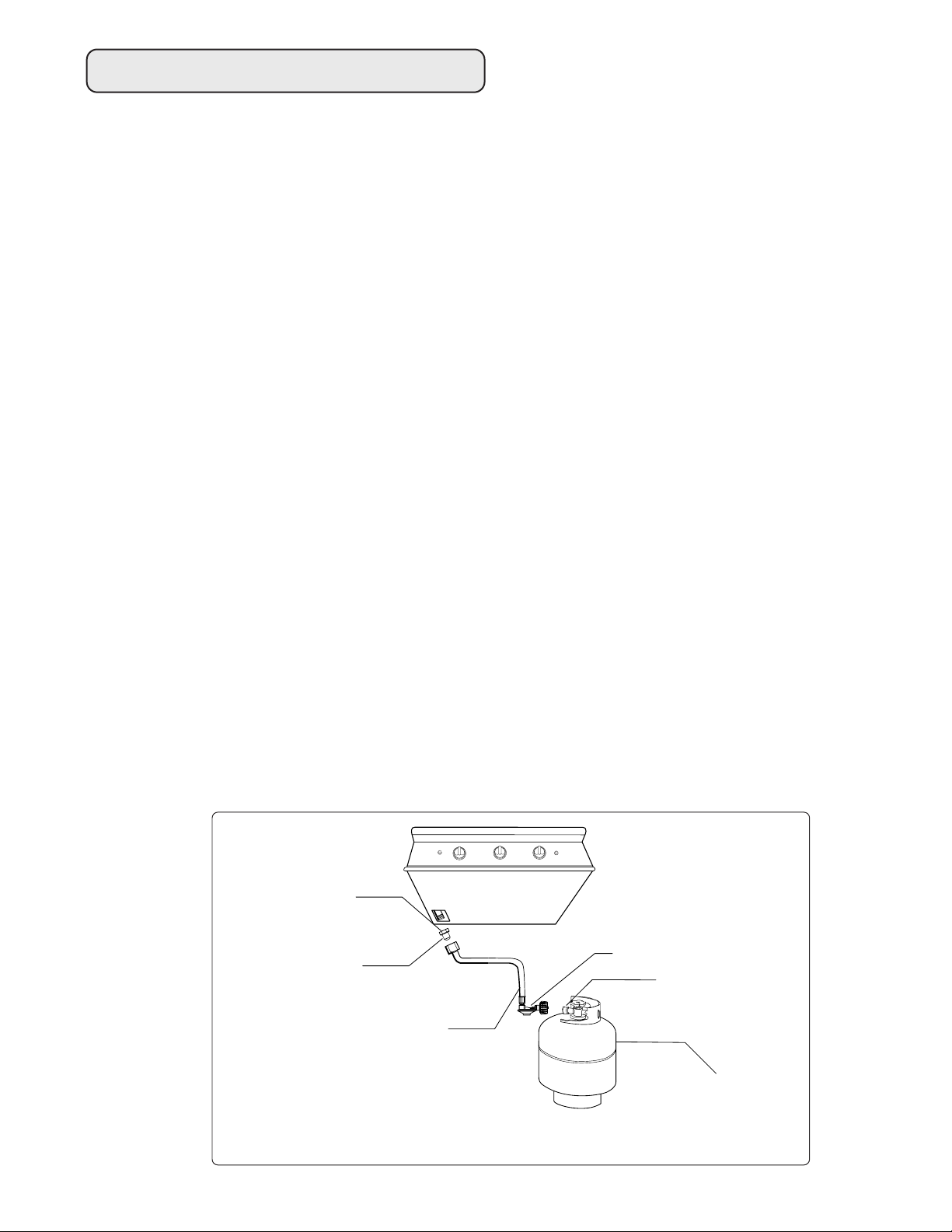
LP GAS HOOK UP (TYPE 1 OR QCC1
REGULATOR):
Grills orificed for use with LP gas come equipped
with a high capacity hose/regulator assembly for
connection to a standard 20 lb. LP cylinder
(Type 1). The LP tank is not included.
Connection: 1/2" NPT male with a 3/8" Flare
adapter (included). LP Hose with a quick
disconnect and fittings are included.
Operating pressure: 10.0" W.C.
To connect the LP regulator/hose assembly to the
tank/valve assembly, first make sure the main valve
on the tank is completely closed. Although the
flow of gas is stopped when the Type 1 system is
disconnected as part of of its safety feature, you
should always turn the LP tank main valve (Fig.02)
off after each use and during transport of the tank
or unit. Insert the regulator inlet into the tank valve
and turn to the black coupler clockwise until the
coupler tightens up. Do not overtighten the
coupler. Turn the main tank valve on and turn the
burner control valves on the unit to the “HI”
position for about 20 seconds to allow the air in
the system to purge before attempting to light the
burners.
To disconnect the coupler, first make sure the main
tank valve is turned off. Grasp the coupler and
turn counter clockwise. The inlet will then
disengage, remove the inlet from the tank valve
opening if it has not already done so when it
Bottom of unit
Threading Compound
must be resistant to
LP gas
Type 1 Regulator
Main Valve
Adapter 1/2 NPT to
3/8 flare fitting
Do not put threading
compound on these
threads
LP Regulator hose
assemby 10 W.C.
Installation must conform with local
codes or with the National Fuel Gas
Code ANSI Z223.1
Type 1 Tank
disengaged. Your local LP filling station should be
equipped with the proper equipment to fill your
tank.
LP TANK REQUIREMENTS:
A dented or rusty LP tank may be hazardous and
should be checked by your LP supplier. Never use
a cylinder with a damaged valve. Always check for
leaks after every LP tank change. The LP gas
cylinder must be constructed and marked in
accordance with the specifications for LP gas
cylinders of the U.S. Department of Transportation
(DOT) and designed for use with a Type 1 system
only. Do not change the regulator/hose assembly
from that supplied with the unit or attempt to use a
Type 1 equipped regulator/hose assembly with a
standard 510 POL tank/valve assembly. The
cylinder must be provided with a shut-off valve
terminating in an LP gas supply cylinder valve
outlet specified, as applicable, for connection
Type 1. If the appliance is stored indoors the
cylinder must be disconnected and removed from
the appliance. Cylinders must be stored outdoors
in a well-ventilated area out of the reach of
children.
Note: When a LP unit is directly attached
into a LP house system, the step
down regulator
MUST be used to
reduce the supply pressure to a max.
14” W.C. and min. 11” W.C. to the
grill regulator.
FIG.02
LP Gas
Gas Requirements

8
INSULATED JACKET:
Do not build the Grill under overhead unprotected
combustible construction. If the Grill is to be
placed into a combustible enclosure, an approved
insulated jacket is necessary and is available from
your dealer. Use only the insulated jacket which
has specifically been designed and tested for this
purpose.
LOCATION:
When determining a suitable location take into
account concerns such as exposure to wind,
proximity to traffic paths and keeping any gas or
electrical supply lines as short as possible. Locate
the grill only in a well ventilated area. Never locate
the grill in a building, garage, breezeway, shed or
other such enclosed areas without an approved
ventilation system. During heavy use, the grill will
produce a lot of smoke. Ensure there is adequate
area for it to dissipate.
IMPORTANT: Gas fittings, regulator,
and installer supplied shut-off valves
must be easily accessible.
Locating Grill / Built-In Clearances
CLEARANCES TO COMBUSTIBLE
CONSTRUCTION:
A Minimum of 12" from the sides and a minimum
of 12" from the back must be maintained from the
Grill above and below the cooking surface to
adjacent vertical combustible construction.
CLEARANCES TO NON-COMBUSTIBLE
CONSTRUCTION:
A minimum of 3" clearance from the back of the
grill to non-combustible construction is required for
the purpose of allowing the lid to open fully. It is
desirable to allow at least 6" side clearance to noncombustible construction above the cooking
surface for counter space. If you’ll be using the
rotisserie option, the space is essential for motor
and skewer clearance. The Grill can be placed
directly adjacent to non-combustible construction
below the cooking surface.
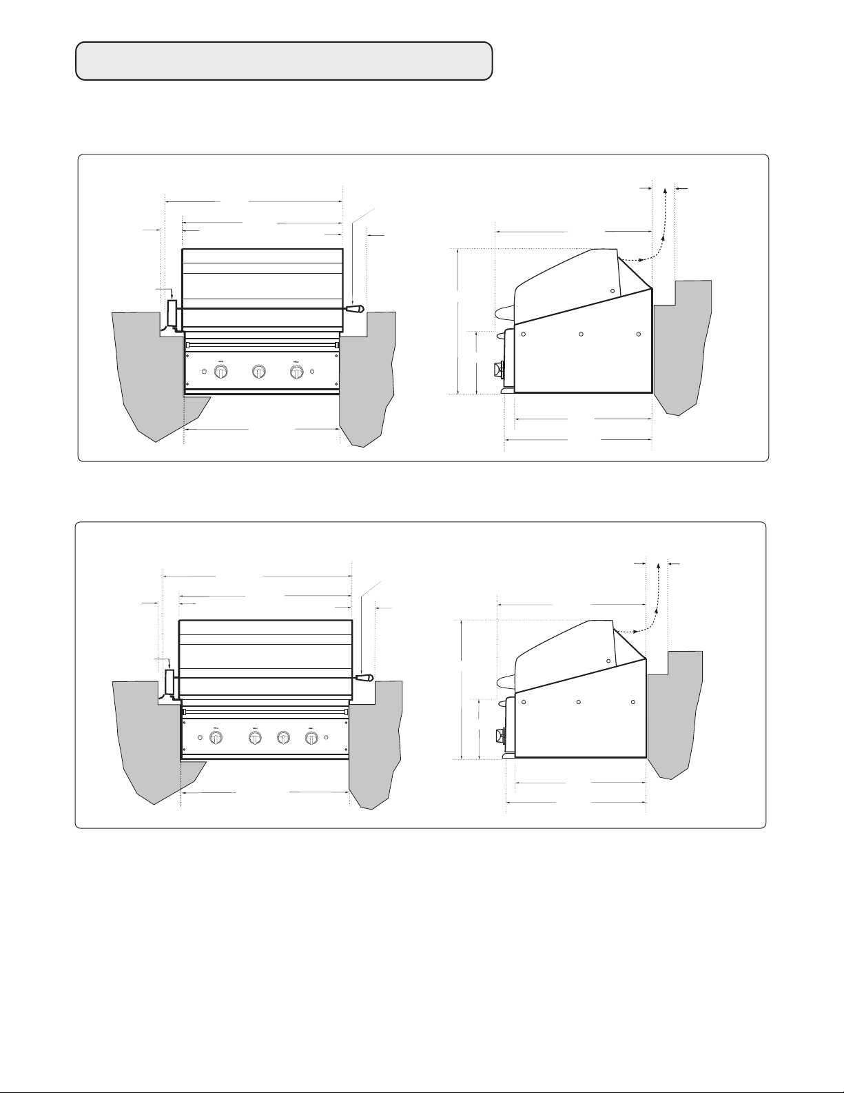
9
ROTISSERIE
SAFETY
IGNITION
(to left and right
side of grill to
combustible
construction)
(with rotisserie motor mounted)
rotisserie motor
(lid)
6"
36"
27
3/4"
27
3
/8
"
(cutout)
3" (to non-
combustible
construction/
min. lid
clearance)
12"
(to combustible
construction)
grill
exhaust
26
1
/2
"
(to left and
right side of
grill to
combustible
construction)
6"
rotisserie handle
22"
24
7
/8
"
24
3
/8
"
10
1
/2
"
GENERAL:
The Grill is designed for easy placement into
masonry enclosures. For non-combustible
applications the grill drops into the opening shown
in (Fig. 05 & Fig. 06). A deck or ledge is required to
support it from the bottom. When using the
insulated jacket in a combustible enclosure
application, (Fig. 05 & Fig. 06) bottom, the jacket
assembly must be supported from the bottom by a
ledge on each side or a solid deck beneath the
entire grill or insulated jacket.
Built–In Grill Clearances
FIG.03
Review the detail drawings shown and take into
account the provisions shown for gas line hook-up
clearance in the left rear corner. It is
recommended that ventilation holes are provided in
the enclosure in the event of a gas leak. The
supporting ledges or deck must be level and flat.
The counter should also be level.
FOR MODEL 27”
FOR MODEL 36”
R
O
T
I
S
S
E
R
I
E
SAFETY
IGNITION
(to left and right
side of grill to
combustible
construction)
(with rotisserie motor mounted)
rotisserie motor
(lid)
6"
45"
36
3
/4
"
36
3
/8
"
(cutout)
3" (to non-
combustible
construction/
min. lid
clearance)
12"
(to combustible
construction)
grill
exhaust
26
1
/2
"
(to left and
right side of
grill to
combustible
construction)
6"
rotisserie handle
22"
24
7
/8
"
24
7
/8
"
10
1
/2
"
FIG.04
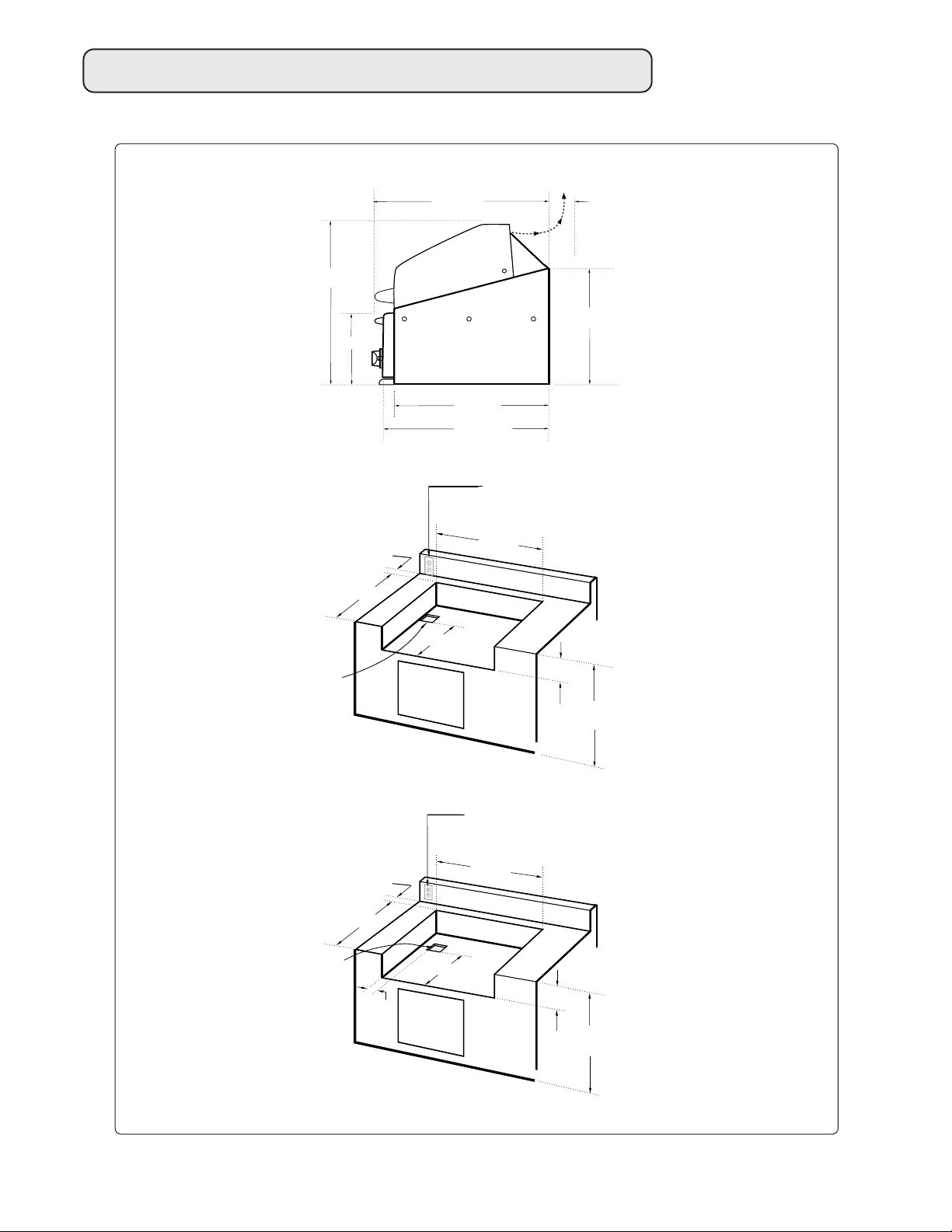
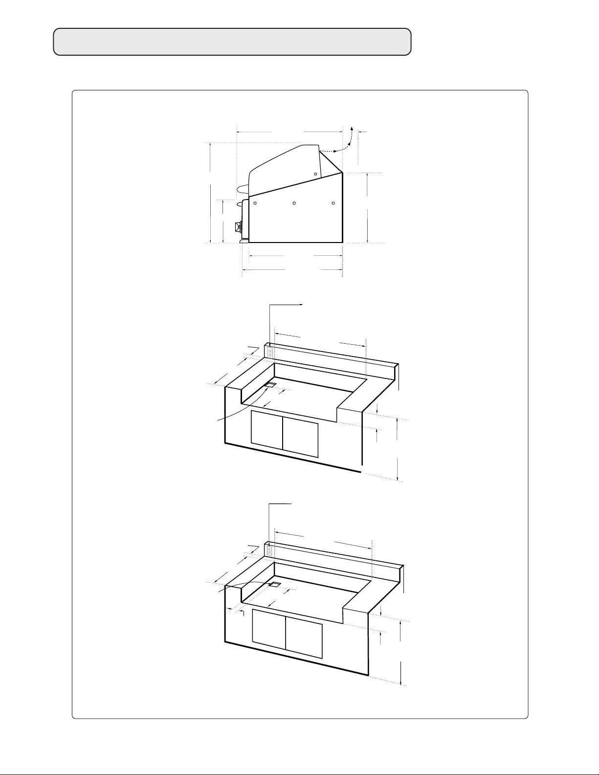
10
3" (to non-combustible
construction / min. lid
clearance)
12" (to combustible
construction)
grill
exhaust
NOTE: If using a backguard apron or rear wall, locate
electrical service on the left hand side for rotisserie
motor connection
STANDARD LAYOUT FOR NON-COMBUSTIBLE ENCLOSURE:
3" min. for lid
clearance
INSULATED JACKET LAYOUT FOR COMBUSTIBLE ENCLOSURE:
NOTE: If using a backguard apron or rear wall, locate
electrical service on the left hand side for rotisserie
motor connection
3" min. for lid
clearance
4" X 4" opening for
gas supply line
4" X 4" opening for gas
supply line
24
3
/8
"
10
1
/2
"
22"
24
7
/8
"
16
1
/4
"
26
1
/2
"
27
3
/8
"
23"
10
3
/8
"
35
1
/2
"
max.
14
1
/2
"
11
3
/8
"
35
1
/2
"
max.
33
3
/8
"
14
1
/2
"
3"
24"
Built–In Construction Details – 27”
FIG.05
11
Built–In Construction Details – 36”
3" (to non-combustible
construction / min. lid
clearance)
12" (to combustible
construction)
grill
exhaust
NOTE: If using a backguard apron or rear wall, locate
electrical service on the left hand side for rotisserie
motor connection
STANDARD LAYOUT FOR NON-COMBUSTIBLE ENCLOSURE:
3" min. for lid
clearance
INSULATED JACKET LAYOUT FOR COMBUSTIBLE ENCLOSURE:
NOTE: If using a backguard apron or rear wall, locate
electrical service on the left hand side for rotisserie
motor connection
3" min. for lid
clearance
4" X 4" opening for
gas supply line
4" X 4" opening for gas
supply line
24
7
/8
"
10
1
/2
"
22"
24
7
/8
"
16
1
/4
"
26
1
/2
"
36
3
/8
"
23"
10
3
/8
"
35
1
/2
"
max.
14
1
/2
"
11
3
/8
"
35
1
/2
"
max.
42
3
/8
"
14
1
/2
"
3"
24"
FIG.06