

DCS DRHRMT Installation Manual
DEL REY HEATER REMOTE CONTROL KIT
INSTALLATION INSTRUCTIONS
IMPORTANT!
Read all instructions before you begin. Do not jump ahead or skip any step.
CAUTION!
Some parts may have sharp edges; care must be taken when handling the various components
to avoid injury. Please read safety information provided in these instructions before beginning
assembly. Be sure to have a qualified technician install and ground this appliance before using.
CONTENTS INCLUDED:
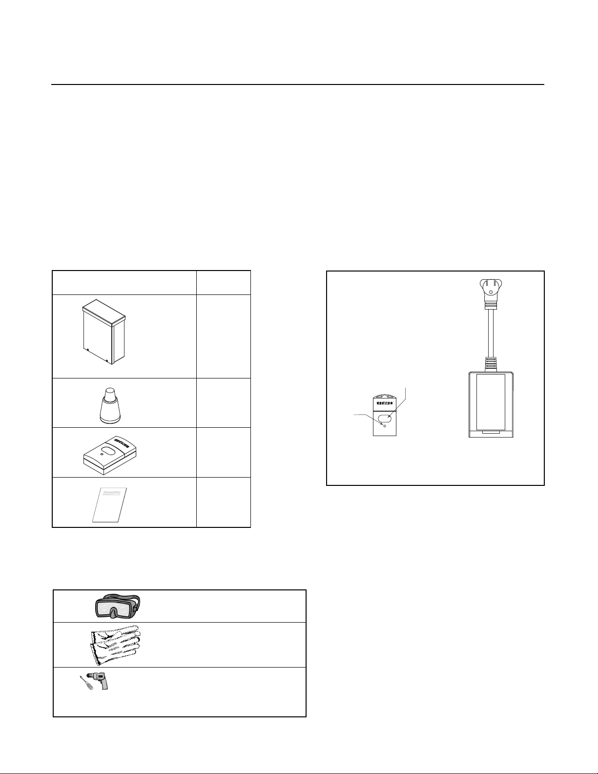
The package contains a weather-proof receiver assembly, wire nuts, a transmitter remote control and
installation sheet (Fig. 01 & 02).
Fig. 02
Fig. 03
Fig. 01
Contents Qty.
1
6
1
1
TOOLS REQUIRED:
Receiver Assembly
Wire Nuts
Transmitter
Transmitter Receiver,
inside Receiver Assembly
Instruction
Eye Goggles
Work Gloves
Power Screwdriver or
Variable Speed Drill with
Phillips -tip #2 Attachment
Control
Button
Activation
light

FCC
This device complies with part 15 of the FCC Rules. Operation is subject to the following two conditions:
1. This device may not cause harmful interference.
2. This device must accept any interference received, including interference that may cause undesired
operation.
WARNING
Changes or modifications to this unit not expressly approved by DCS by Fisher & Paykel could
void the user’s authority to operate the equipment. DCS by Fisher & Paykel will not be held liable
or responsible for any misuse or application of this product other than for its intended use.
SPECIFICATIONS
RANGE: Up to 100 feet
INPUT: 120 VAC 60 Hz
MAXIMUM LOAD: 300W
BATTERY (TRANSMITTER): 12-volt alkaline battery
(type 23AE, see Fig. 04)
ELECTRICAL
This kit contains the 24 VAC, 40 VA transformer and remotely controlled switch that’s needed for proper
operation. If this is an upgrade to an existing installation, discard the transformer that is currently installed
with your heater (DCS DRH-48N). It’s no longer needed. Follow the electrical diagram to connect the heater to
the transformer wires included in this kit and to connect the electrical supply line to the switch receptacle
(Fig. 05~07).
Each remote control box must be electrically grounded and installed in accordance with the local codes or, in
the absence of local codes with the National Electrical Code, ANSI/NFPA 70. Use at least 18 AWG wire up to 50
ft from heater to remote control unit. Use 16 AWG over 50 ft distance. If the original wires supplied should
need replacement, they must be replaced with wiring material having a temperature rating of at least 105°C.
The on-off control of the heater is controlled by the transmitter (Fig. 02). This unit provides 24 VAC power
to your Del Rey built-in patio heater.
NOTE: Aim the transmitter at the box when operating.
Fig. 04
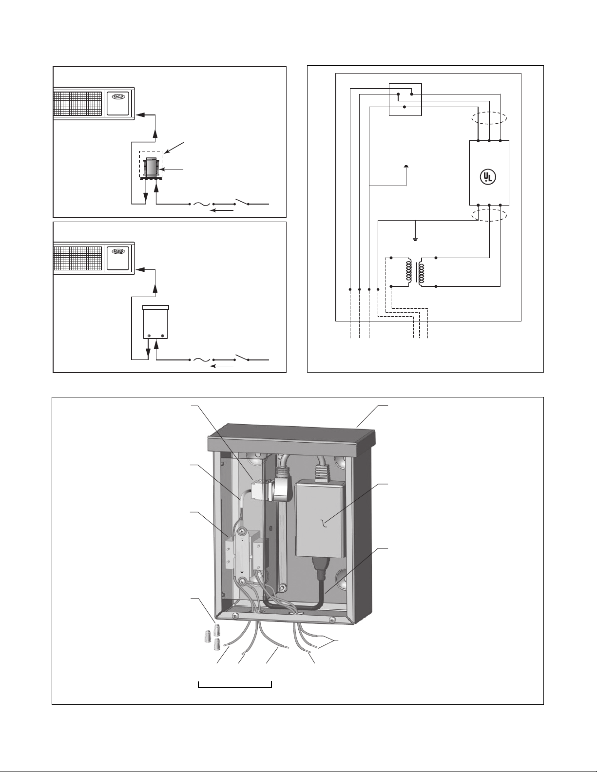
Fig. 07
Black
(Line)
White
(Nut.)
Input 110 VAC
Green
(Grd.)
Green
(Grd.)
NL
Transformer
EXISTING TRANSFORMER CONFIGURATION
REMOTE CONTROLLED CONNECTION
24 VAC Input
115 VAC Power
24 VAC Input
115 VAC Power
24 VAC
24 VAC
Existing transformer is replaced
with the receiver assembly
Weatherproof protective
enclosure
Fig. 05
Fig. 06
Receiver
Pre-wired Pigtail
Interface
Enclosure
Pre-wired 115 VAC
Receptacle
Harness with
Receptacle
24 VAC Transformer
Wire Nuts (
Output
24 VAC wires
RECEPTACLE
N
GG
L
18 CA AWG INPUT
(110 VAC MIN. 60 Hz, 10 Amp)
G
GROUND
CHASSIS
GROUND
CHASSIS
24 VAC
110 VAC
STEP DOWN
TRANSFORMER
18 AWG OUTPUT
(24 VAC MIN.) TO HEATER
REMOTE
SENSOR
9HX9
APPLIANCE
CONTROL
 Loading...