

DCS DISHDRAWER DD124P5, DISHDRAWER DD224P5 Installation Manual
MODELS:
DD124P5
DD224P5
DISHDRAWER®
Installation Guide
Important safety precautions!
Installation of this DishDrawer® requires basic mechanical and electrical skills.
Be sure to leave these Instructions with the Customer.
Installation must comply with your local building and electricity regulations.
At the completion of the DishDrawer® installation, the Installer must perform
Final Check List on Page 29.
Remove all packaging materials supplied with the DishDrawer®.
This dishwasher is manufactured for indoor use only.
Ensure all water connections are turned OFF. It is the responsibility of the plumber and
electrician to ensure that each installation complies with all Codes and Regulations.
The DishDrawer® MUST be installed to allow for future removal from the enclosure if service is
required.
The switched power outlet must be outside the DishDrawer® cavity so that it is accessible after
installation.
Care should be taken when the appliance is installed or removed to reduce the likelihood of
damage to the power supply cord.
If the DishDrawer® is to be relocated from one installation to another it must be kept upright to
avoid damage from water spillage.
Make sure only new hoses are used for connection (supplied with DishDrawer®).
Old hoses should not be reused.
Failure to install the DishDrawer® correctly could invalidate any warranty or liability claims.
If the product is installed in a motor vehicle, boat or similar mobile facility, you must bring the
vehicle, boat or mobile facility containing the product to the service shop at your expense or pay
the service technician’s travel to the location of the product.
WARNING!
Cut Hazard
Take care - panel edges are sharp.
Failure to use caution could result in injury or cuts.
Safety and warnings
WARNING!
Electrical hazard
Before installing the DishDrawer®, remove the house fuse or open the circuit
breaker.
If permanently connecting the DishDrawer®, be sure the power is isolated
and the DishDrawer® unplugged.
This appliance must be grounded. In the event of a malfunction or
breakdown, grounding will reduce the risk of electric shock by providing
a path of least resistance for electric current. This appliance is equipped
with a cord having an equipment-grounding conductor and a grounding
plug. The plug must be plugged into an appropriate outlet that is installed
and grounded in accordance with all local codes and ordinances. Improper
connection of the equipment-grounding conductor can result in a risk of
electric shock. Check with a qualified electrician or service representative if
you are in doubt as to whether the appliance is properly grounded.
Do not modify the power supply plug provided with the appliance - if it will
not fit the outlet, have a proper outlet installed by a qualified electrician. Do
not use an extension cord, adapter plug or multiple outlet box.
Failure to do so may result in electrical shock or death.
US CA

1
Contents
DOUBLE MODELS
Product and cabinetry dimensions
2
Installation
Cavity preparation
4
Optionally hard wiring the product
5
Route the hoses and move into the cavity
6
Removing the tub and levelling the product
7
Securing the product and refitting the tub
8
Fitting the toekick
9
Plumbing and drainage - OPTION 1
10
Plumbing and drainage - OPTION 1 (connection)
11
Plumbing and drainage - OPTION 2
12
Plumbing and drainage - OPTION 2 (connection)
13
Plumbing and drainage - OPTION 3
14
Plumbing and drainage - OPTION 3 (connection)
15
SINGLE MODELS
Product and cabinetry dimensions
16
Installation
Cavity preparation
18
Optionally hard wiring the product
19
Route the hoses and move into the cavity
20
Removing the tub and securing the product
21
Plumbing and drainage - OPTION 1
22
Plumbing and drainage - OPTION 1 (connection)
23
Plumbing and drainage - OPTION 2
24
Plumbing and drainage - OPTION 2 (connection)
25
Plumbing and drainage - OPTION 3
26
Plumbing and drainage - OPTION 3 (connection)
27
Refitting the tub
28
Final checklist
29
Important!
SAVE THESE INSTRUCTIONS
The models shown in this User Guide may not be available in all markets and are
subject to change at any time. For current details about model and specification
availability in your country, please go to our website www.dcsappliances.com or
contact your local DCS Customer Care Representative.
US CA
2
DOUBLE MODELS
US CA
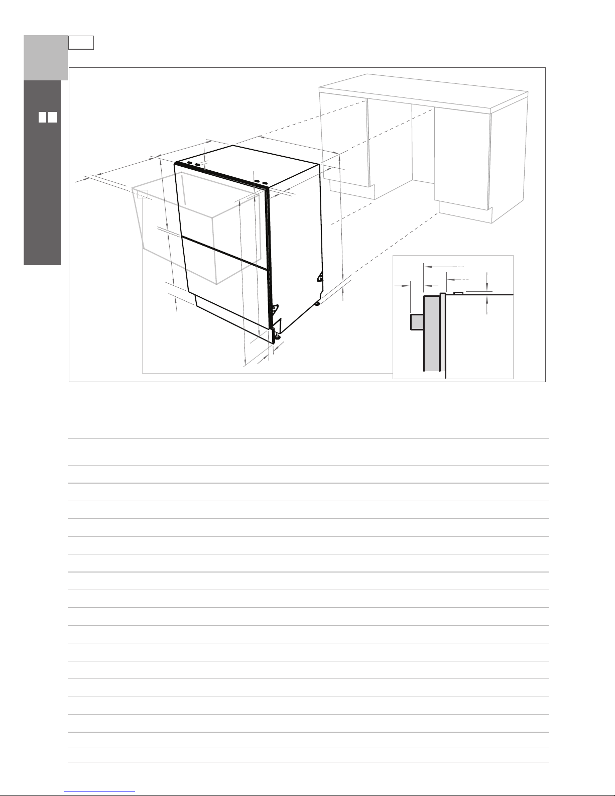
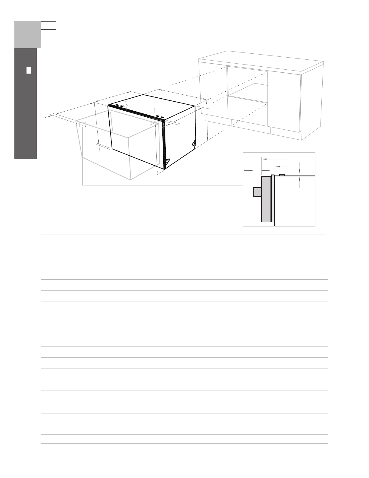
Product dimensions
Product dimensions (inches (mm))
Pre nished
Flat door
DD224P5
A
overall height* of product
32 ¼ - 34 ⁄”
(819.5- 879.5)
B
overall width of product 23 ⁄”(605)
C
overall depth of product (excl. curvature/handle) 22 ⁄” (570)
D
depth of drawer (open) (excl. curvature/handle) 20 ⁄” (520)
E
height* of chassis 31 ⁄” (809)
F
height range of levelling feet 2 ⁄” (60)
G
depth of chassis 21 ¾ ” (552)
H
depth of drawer front panel (excl. curvature/handle) 1” (25)
I
depth of handle 3 ⁄” (81)
J
depth of kickstrip 2 - 4 ⁄” (50 - 110)
K
height of upper drawer front 15 ⁄” (398)
L
height of lower drawer front 14” (356)
M
height of kickstrip (adjustable)
2 ¾ - 4 ¾ ” (70 - 120)
N
height of installation tab slots (on top of chassis) ¾ ” (2)
O
height of drawer fronts 30 ⁄” (764)
P
height* of top of upper drawer to top of chassis ¾ ” (2)
* Chassis heights include tab slots
O
B
C
E
D
F
G
H
J
N
P
I
K
L
M
A
N
G
C
I
Installation diagrams for illustration purposes only
3
DOUBLE MODELS
US CA
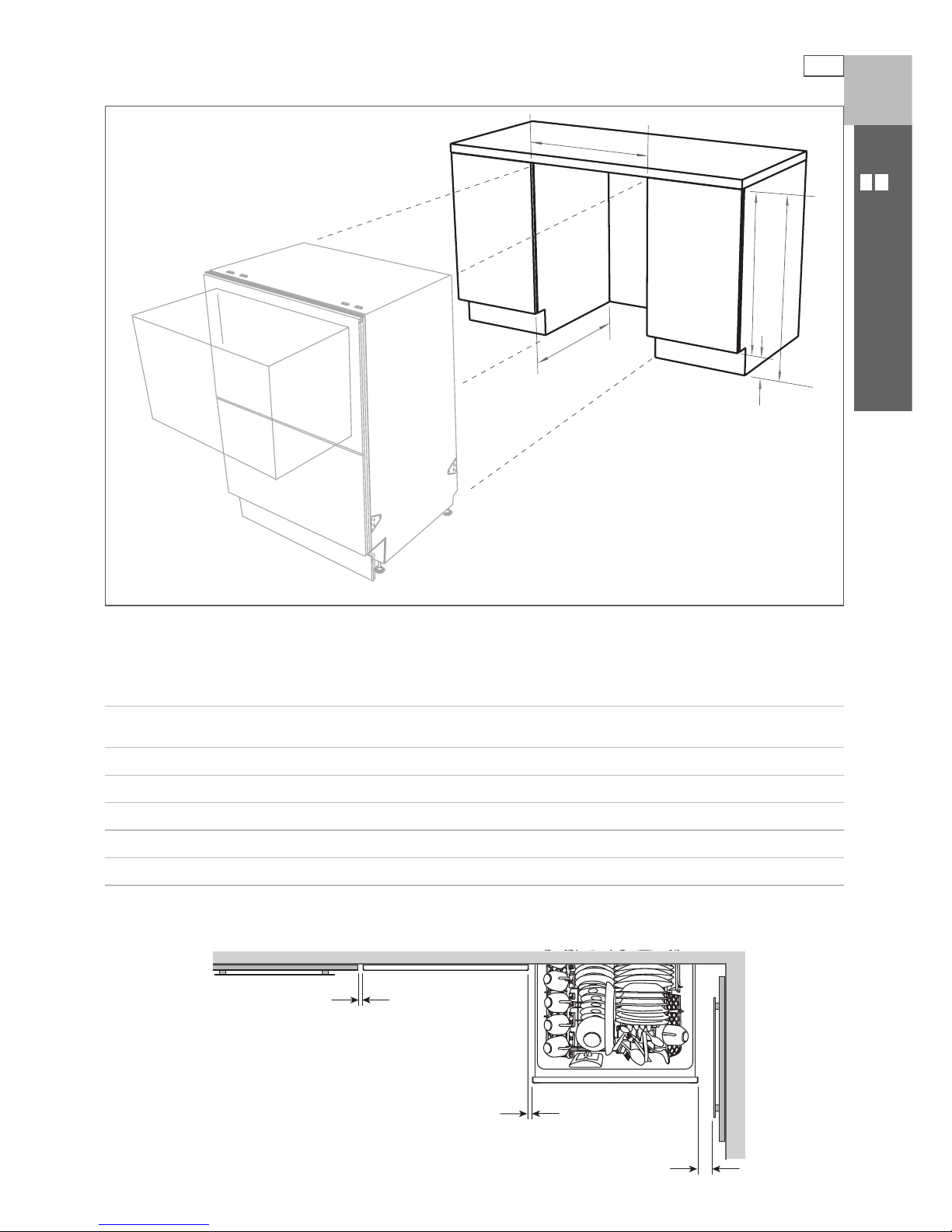
Cabinetry dimensions
A
B
C
D
E
Installation diagrams for illustration purposes only
Cabinetry dimensions (inches (mm))
Pre nished
Flat door
DD224P5
A
inside height of cavity
32 ⁄ - 34 ¾ ”
(820 - 882.5)
B
inside width of cavity 24” (610)
C
inside depth of cavity (inside)
22 ⁄” (580)
D
height of adjacent cabinetry 28 ⁄” (720)
E
height of kickstrip
2 ¾ - 4 ¾ ” (70 - 120)
Minimum clearances (inches (mm))
⁄” (2.5 mm)
⁄
” (2.5 mm)
½
” (13 mm)
4
90
o
2” x 4”
DOUBLE MODELS
US CA
Note: Services can be located
either side of DishDrawer®.
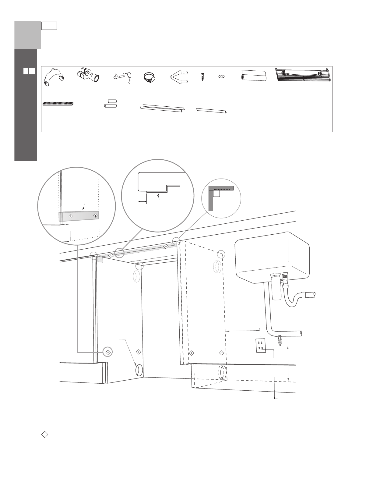
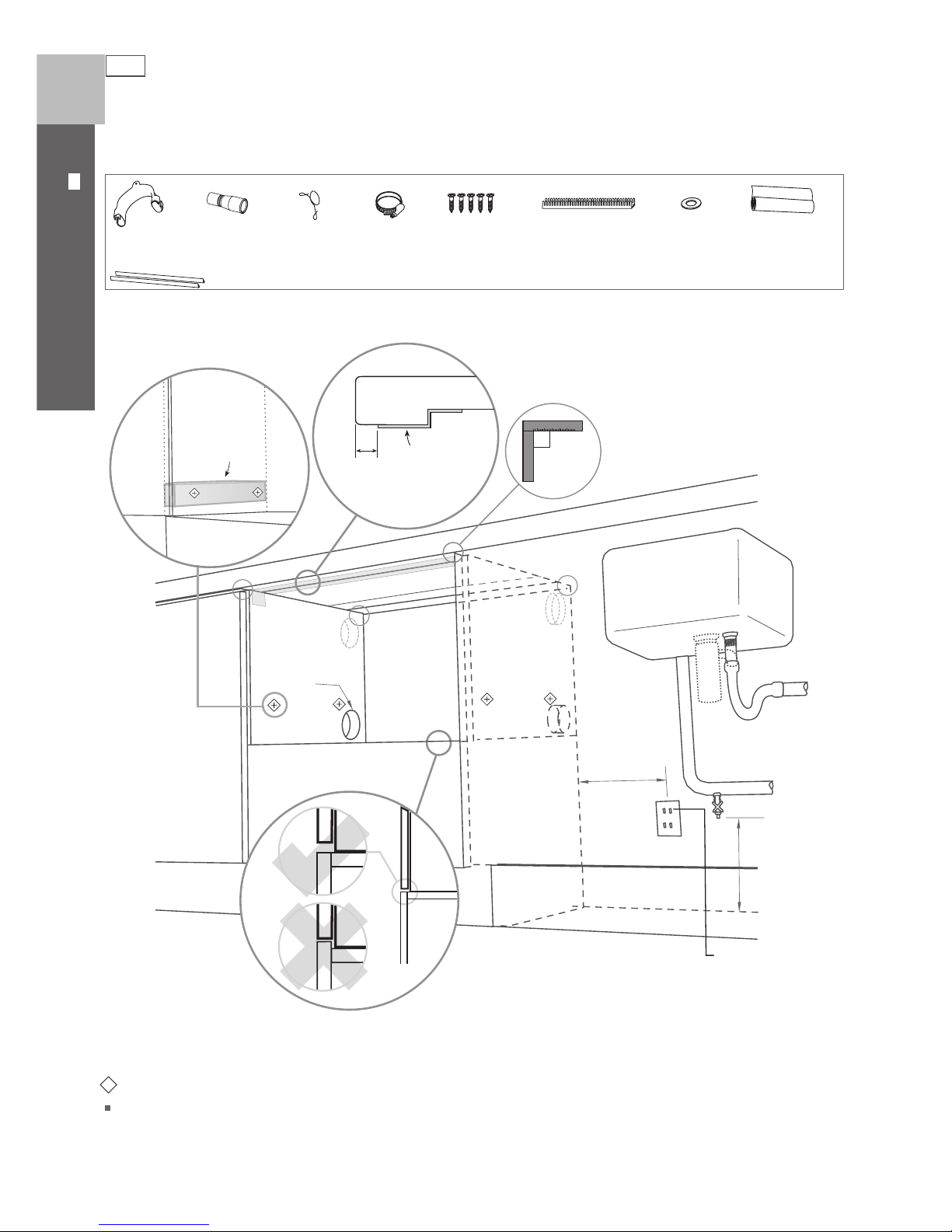
Cavity preparation
Parts supplied
Important!
Be sure the edges of the services hole are smooth or covered. If the service hole is through a metal partition
the hole must be protected with the Edge Protector supplied to prevent damage to the power cord or hoses.
These marks indicate mounting tab screw locations
Preferred position. If adequate clearance, services hole can be higher to clear toe kick space.
If hole is higher, ensure drain hose(s) are routed straight into the waste connection.
110-120 VAC
max. 15 A
Moisture
protection
tape must
be applied.
max. ø
1 ½ ” (
38 mm)
*
*
*
min.
7 ⁄”
(
200 mm)
Clamp (1)
Wire clip (2)
Phillips
16 mm
screws (9)
Drain hose
support (1)
Moisture
protection
tape (1)
(to prevent
moisture damage)
Drain hose
joiner (1)
Install
tabs (2)
Prefinished toe kick (1)
White or Black
Washer (1)
Edge Protector (1)
(if service hole
partition is metal)
⁄”
(
10 mm)
max.
17 ⁄”
(
450 mm)
If no side partition,
use a brace for
securing.
If the Drain hose(s) supplied are not long enough to reach your services, you must use a Drain Hose Extension Kit
P/N 525798 which will extend the drain hose(s) by 3.6m. The kit is available from the nearest DCS
Authorized Service Agent, or by phone: 1-888-281-5698, or www.dcsappliances.com. DO NOT extend beyond this limit.
Hexagonal
socket (2)
(Long & Short)
Side flexible
extrusions (2)
Top flexible
extrusion (1)
5
DOUBLE MODELS
US CA
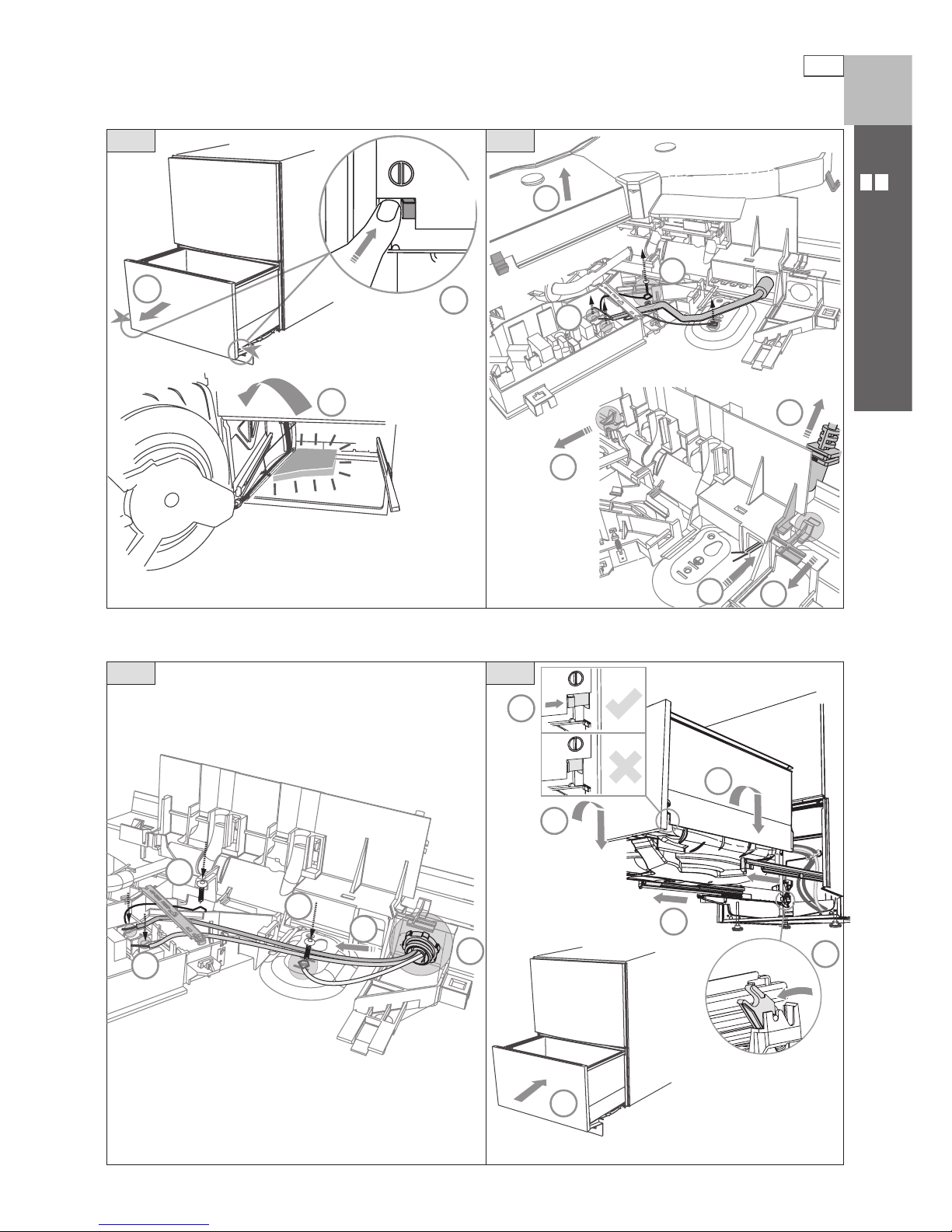
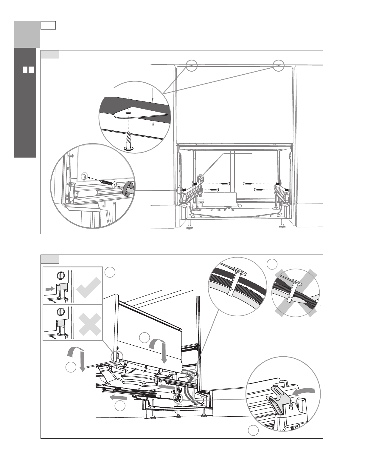
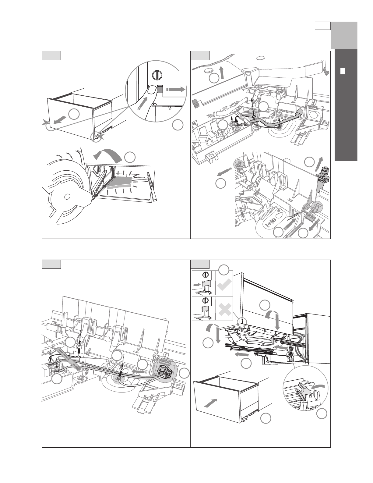
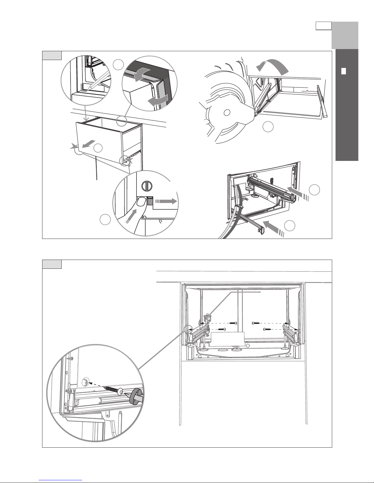
Optionally hard wiring the product
30 mm
1
2
3
4
5
6
7
9
7
8
8
13
17
14
15
15
16
12
11
11
10
4
1 2
3
1 ⁄”
(
30 mm)
Ensure the tub is removed and
then rotated counter-clockwise
to prevent kinked hoses.
Before refitting the tub,
ensure the hoses are not
twisted and the latches at
the rear of each drawer
runner are facing forward.
Ensure the tub clips on
both sides are reset.
Ensure the tub is
now rotated
clockwise back.
Remove power supply cord.
Remove knock-out for cable
clamp. Fit suitable cable clamp for
the conduit and terminate the
wiring as shown.
6
DOUBLE MODELS
US CA
2
3
1
1
1
2
4
4
optional
1b
2
optional
1a
Tie together to avoid kinking.
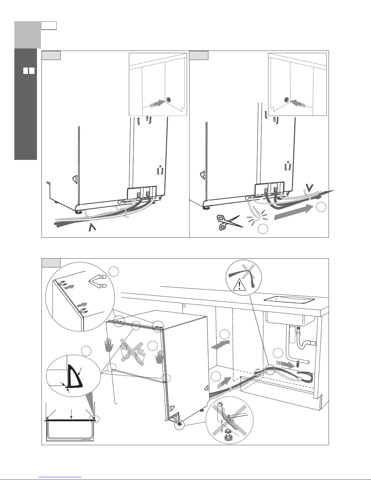
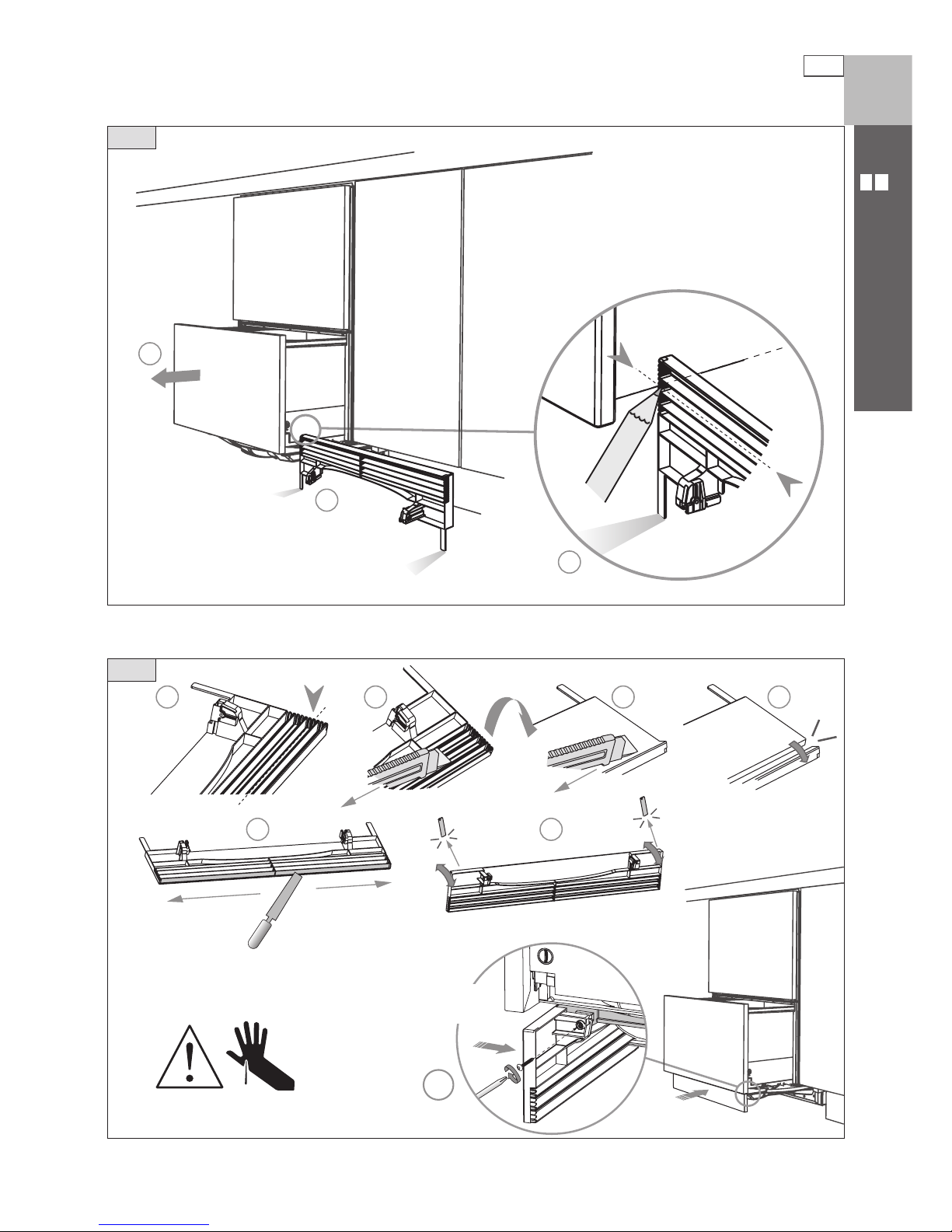
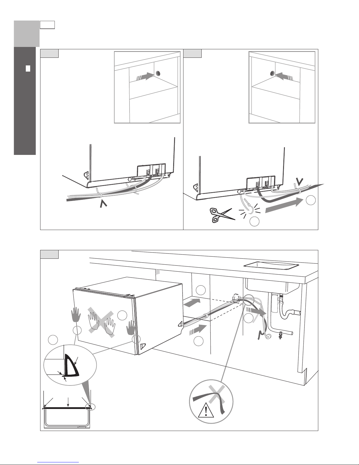
Route the hoses and move into the cavity
If top two tabs are being used,
ensure they’re securely fitted
before sliding product into
cavity.
Ensure hoses and cord
are not kinked or twisted.
Loosen feet first, but
do not fully extend
until product is in cavity.
Side
extrusion
Lip
Chassis
trim
edge
Flexible
extrusions
Open drawer
If cavity is bigger than
specified (Pg 3), flexible
extrusions can be stuck along
the top and sides of the product.
Ensure extrusions do not prevent
the drawer from closing completely.
7
DOUBLE MODELS
US CA
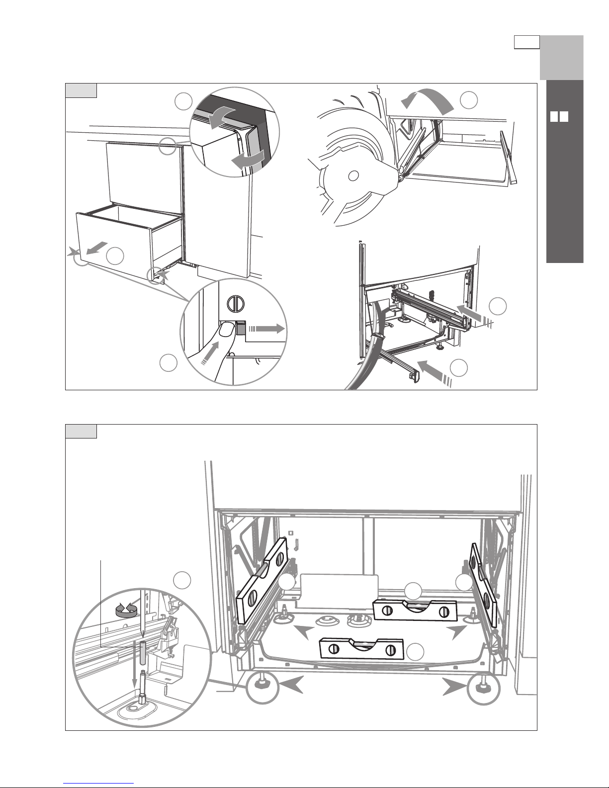
Removing the tub and levelling the product
30 mm
x 4
1
2
3
4
5
5
1
2
3
4
5
3
4
Ensure the tub is removed and
then rotated counter-clockwise
to prevent kinked hoses.
Ensure product is level. Using the most appropriate length
Hexagonal socket supplied, and a screwdriver, fully extend
levelling feet up to required distance.
Hexagonal socket
8
DOUBLE MODELS
US CA
Securing the product and re tting the tub
A
1
2
4
5
4
3
C
C
BB
A
5
optional
6
max.
¾ ” (19 mm)
The mounting tabs
are in pairs, one on
each side of the
product. At least two
sets of tab pairs must
be used.
A and B tab pairs
OR B and C tab pairs
or all three pairs.
Ensure the sound
insulation is
repositioned
correctly.
Before refitting the tub,
ensure the hoses are not
twisted and the latches at
the rear of each drawer
runner are facing forward.
Ensure the tub clips on
both sides are reset.
Ensure the tub is
now rotated
clockwise back.
9
DOUBLE MODELS
US CA
1
2
3
4 5 6 7
8 9
10
19
7
8
Important!
D o not overtighten screw.
Fitting the toekick
10
DOUBLE MODELS
US CA
DishDrawer® with Waste Disposal
Water Pressure Max Min
Water softener models 1 MPa (145 psi) 0.1 MPa (14.5 psi)
Other models 1 MPa (145 psi) 0.03 MPa (4.3 psi)
Drains will need to be separated to satisfy Kosher requirements. We suggest you confirm
acceptability with your local Rabbi in respect to Kosher installations.
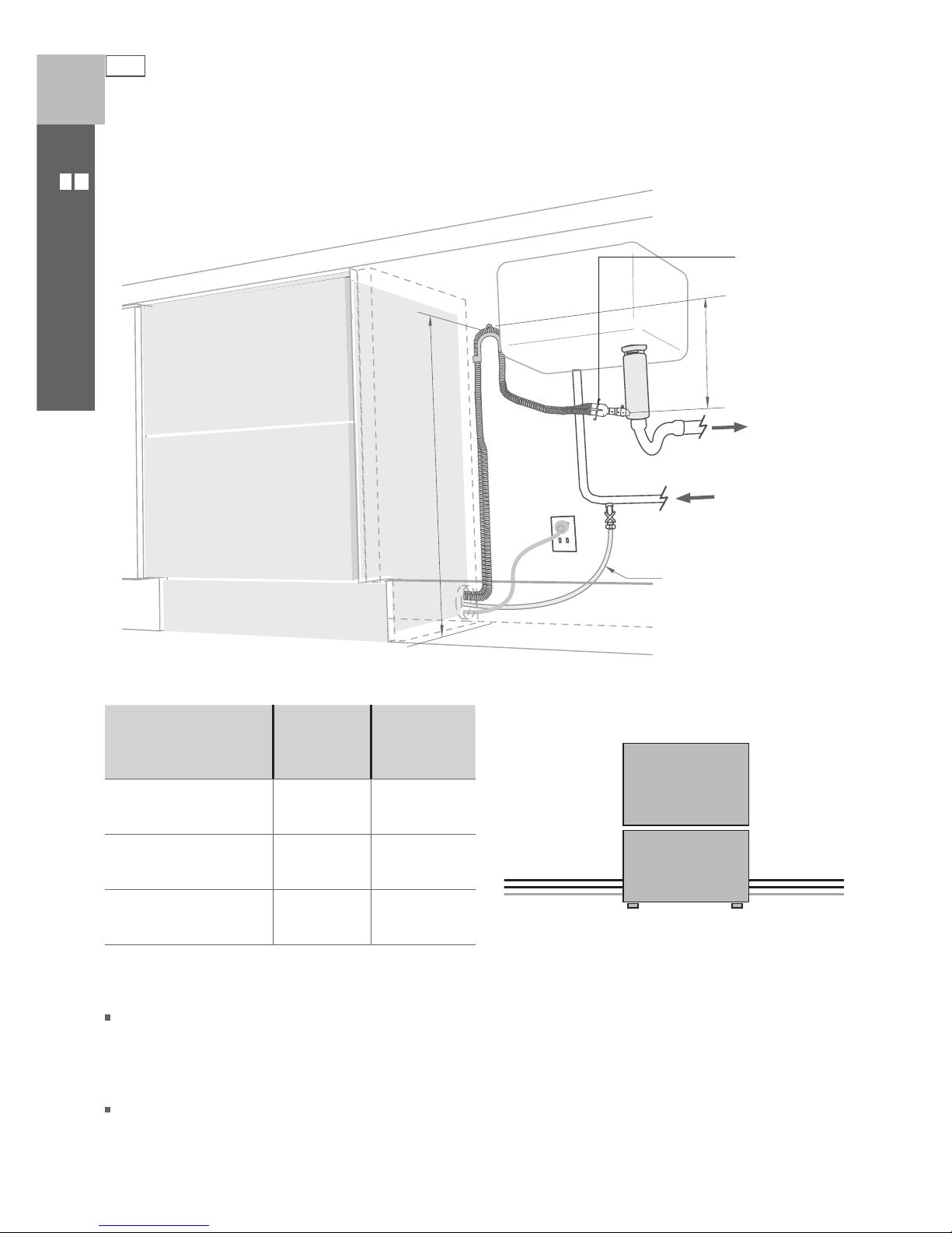
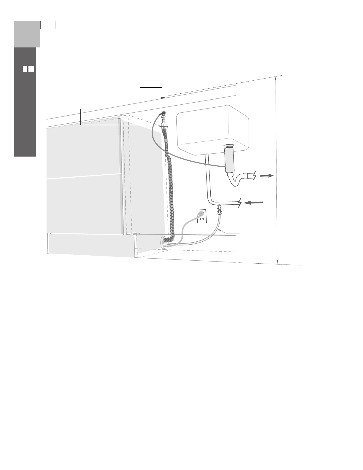
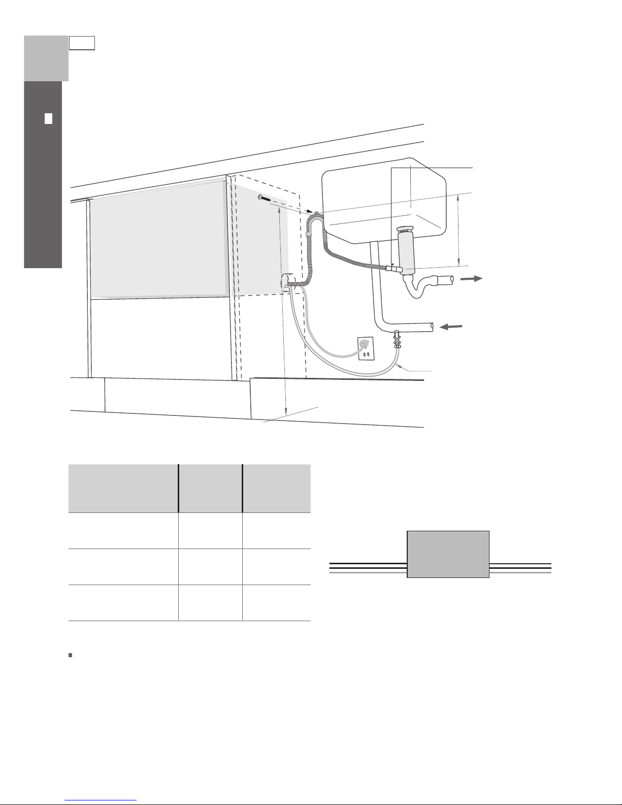
Plumbing and drainage - OPTION 1
29 ½ ” - 34 ¾ ”
(
750 - 882.5 mm)
Waste
Valve
Water
supply
(HOT)
min. R 8 ” (200 mm)
Supplied drain
hose joiner
(ø
¾
” (19 mm))
waste tee)
HIGHLOOP
min. 6” (150 mm)
Max. distance of
hoses and cord from
chassis edge
Left hand
side
Right hand
side
Drain hose
79”
(2011 mm)
71”
(1794 mm)
Inlet hose
61”
(1561 mm)
53”
(1344 mm)
Power cord
70”
(1776 mm)
61”
(1559 mm)
Left hand
side
Right hand
side
11
DOUBLE MODELS
US CA
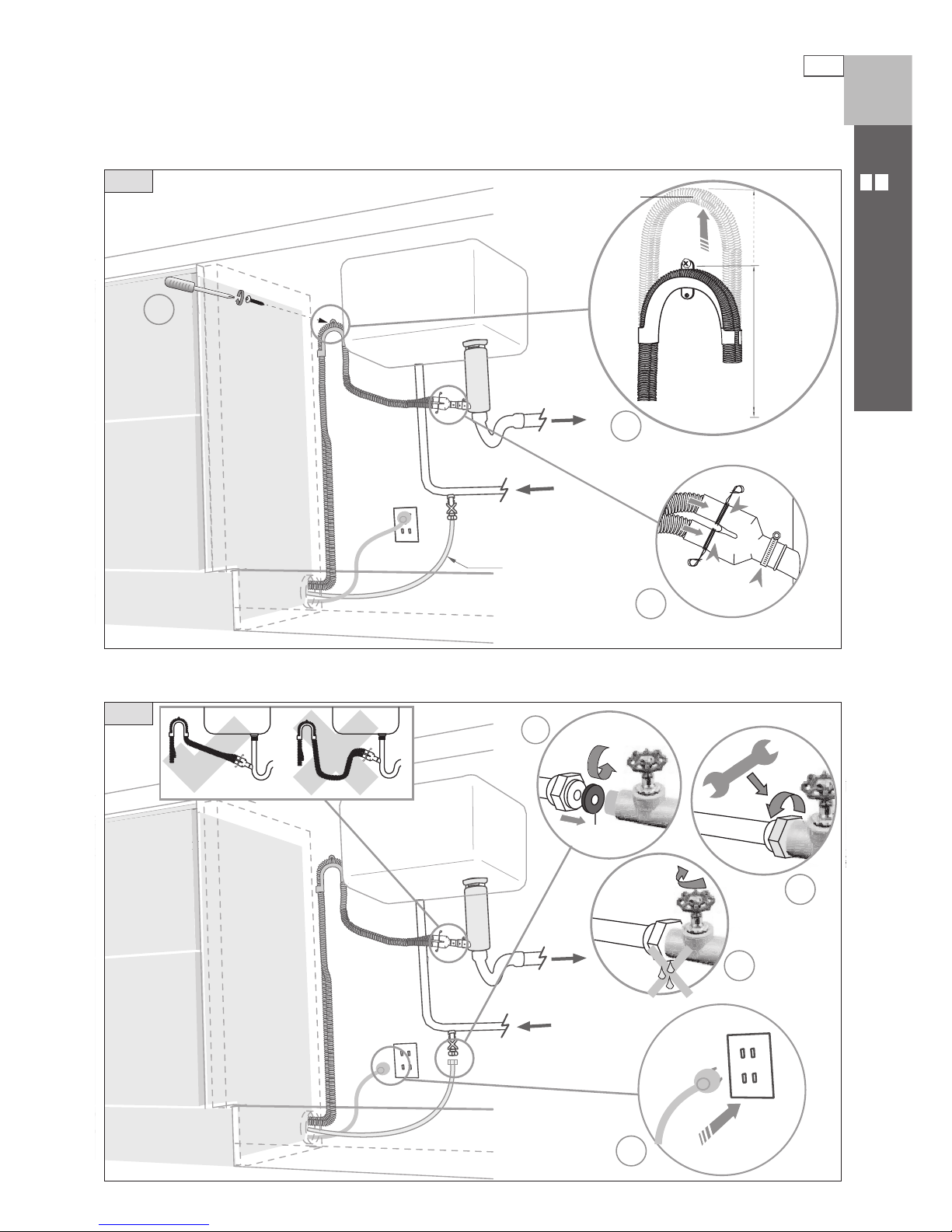
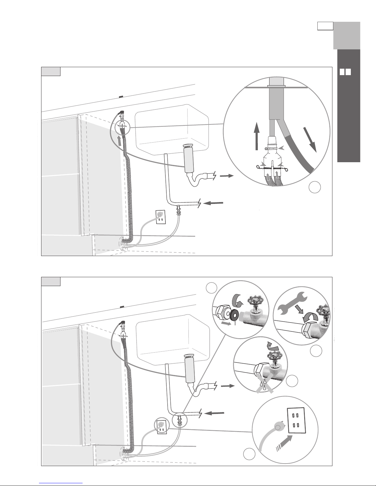
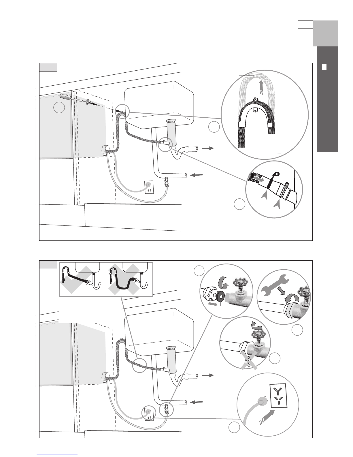
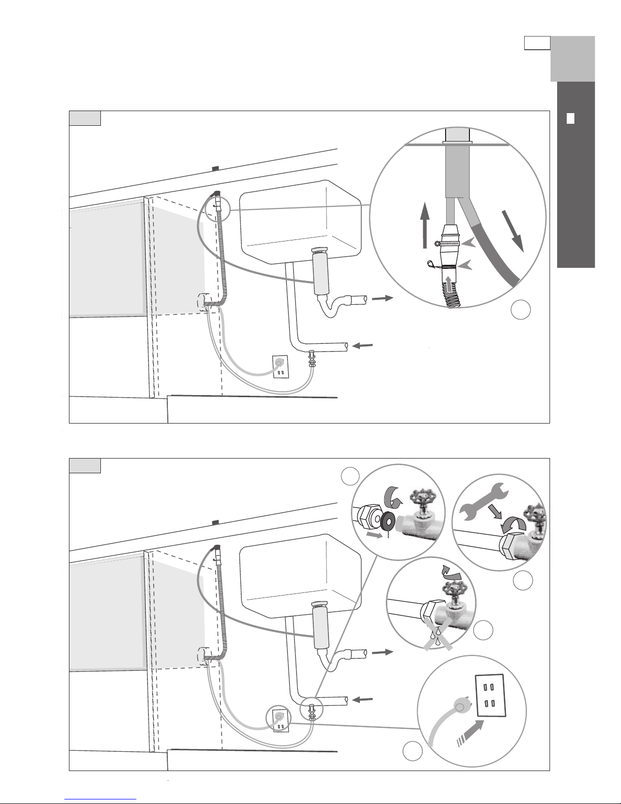
Plumbing and drainage - OPTION 1 (connection)
3
2
1
4
2
29 ½” - 34 ¾”
(750 -
882.5 mm)
1
3
If space is limited
for fixing, push hose
through drain hose
support to required
height
DishDrawer® with Waste Disposal
9
10
Fit supplied
washer
Ensure hoses are routed
straight to joiner. Remove
excess hose material if
necessary.
12
DOUBLE MODELS
US CA
DishDrawer® using Air Break with Drain Hose Joiner
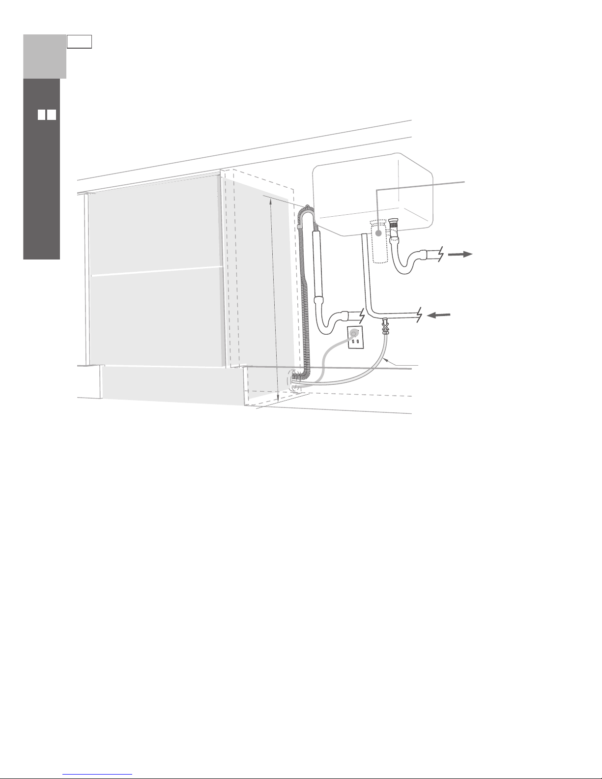
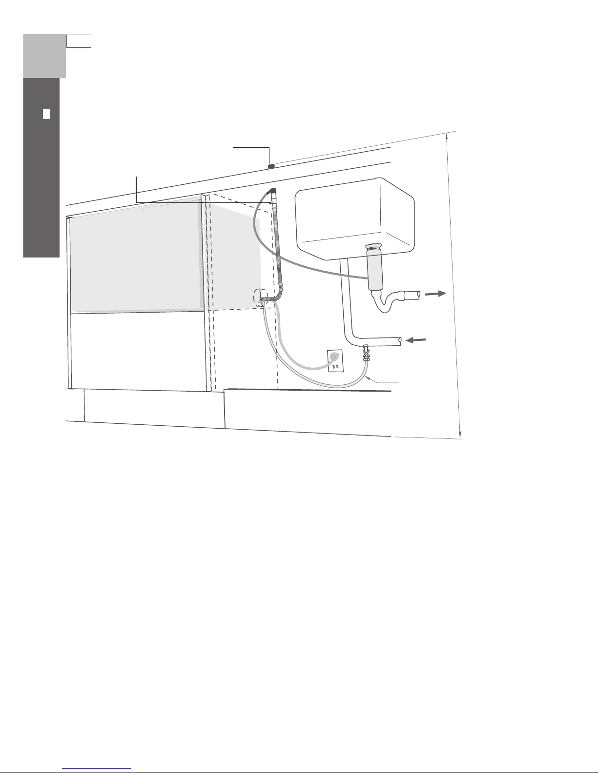
Plumbing and drainage - OPTION 2
Waste
Valve
Water
supply
(HOT)
min. R 8 ”
(
200 mm)
Supplied drain
hose joiner
(ø
¾
” (19 mm))
waste tee)
Air Break
37 ⁄” (950 mm)
Max. height to
top of Air Break
(countertop or
wall mounted)
13
DOUBLE MODELS
US CA
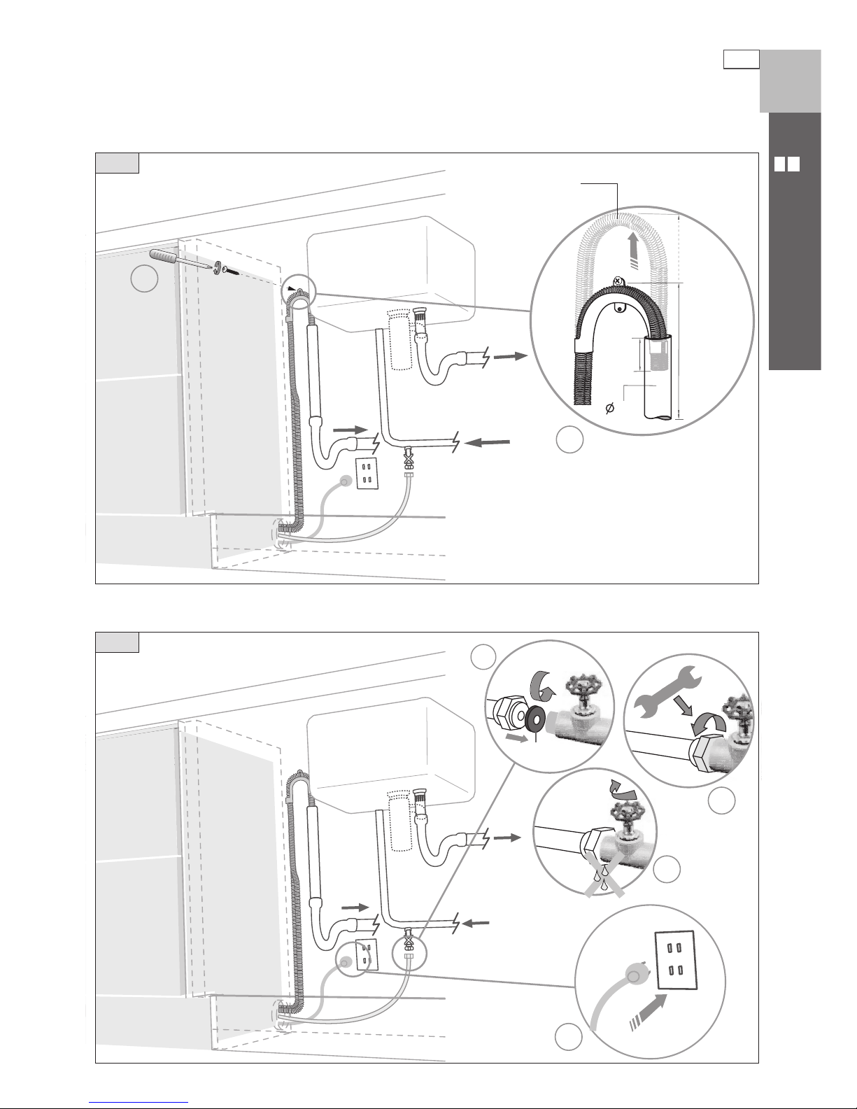
Plumbing and drainage - OPTION 2 (connection)
3
2
1
4
1
DishDrawer® using Air Break with Drain Hose Joiner
9
10
Ensure hoses are routed
straight to joiner. Remove
excess hose material if
necessary.
Fit supplied
washer
14
DOUBLE MODELS
US CA
DishDrawer® and Standpipe Ø
1 ½ ”
(38 mm)
Plumbing and drainage - OPTION 3
29 ½ ” - 34 ¾ ”
(
750 - 882.5 mm)
Waste
Waste
Valve
Water
supply
(HOT)
Waste disposal
(optional)
min. R 8 ” (200 mm)
15
DOUBLE MODELS
US CA
Plumbing and drainage - OPTION 3 (connection)
3
2
1
2
29 ½” - 34 ¾”
(750 -
882.5 mm)
1 ½”
(38 mm)
4
1
max. 4 ¾”
(120 mm)
9
If space is limited
for fixing, push hose
through drain hose
support to required
height
DishDrawer® and Standpipe Ø
1 ½ ”
(38 mm)
10
Fit supplied
washer
16
Product dimensions
SINGLE MODELS
US CA
Product dimensions (inches (mm))
Pre nished
Flat door
DD124P5
A
overall height* of product
16 ⁄” (409)
B
overall width of product
23 ⁄” (605)
C
overall depth of product (excl. curvature/handle)
22 ⁄” (570)
D
depth of drawer (open) (excl. curvature/handle)
20 ½ ” (520)
E
height* of chassis
16 ⁄” (409)
F
depth of chassis
21 ¾ ” (552)
G
depth of drawer front panel (excl. curvature/handle)
1” (25)
H
depth of handle
3 ⁄” (81)
I
height of drawer front
15 ⁄” (398)
J
height of venting area at base of product
⁄” (9)
K
height of installation tab slots (on top of chassis)
⁄” (2)
L
height* of top of drawer to top of chassis
⁄” (2)
*Chassis heights include tab slots
Note: for Pre nished Flat door models, the height from the top of handle to the top of door - 2 ⁄” (59.5 mm)
A
B
C
E
D
F
G
H
J
K
L
I
Installation diagrams for illustration purposes only
K
F
C
H

17
Cabinetry dimensions
A
B
C
D
Installation diagrams for illustration purposes only
SINGLE MODELS
US CA
Cabinetry dimensions (inches (mm))
Pre nished
Flat door
DD124P5
A
inside height of cavity
16 ¼ ” (412)
B
inside width of cavity
24” (610)
C
inside depth of cavity (inside)
22 ⁄” (580)
D
clearance below benchtop
Min. ⁄” (3)*
* Clearance is measured from the underside of benchtop to the chassis
Minimum clearances (inches (mm))
⁄” (2.5 mm)
⁄
” (2.5 mm)
½
” (13 mm)
18
SINGLE MODELS
US CA
Cavity preparation
Cavity
Important!
Be sure the edges of the services hole are smooth or covered. If the service hole is through a metal partition
the hole must be protected with the Edge Protector supplied to prevent damage to the power cord or hoses.
These marks indicate mounting tab screw locations
Note: To align drawer front to adjacent cabinetry, the product to counter top clearance can be
increased to
⁄” (
3 mm).
Preferred position. If adequate clearance, services hole can be higher.
If hole is higher, ensure drain hose(s) are routed straight into the waste connection.
90
o
2” x 4”
Note: Services can be located
either side of DishDrawer®.
Important!
Adjacent cabinetry must not
extend above cavity base
Clamp (1)
Wire clip (1)
Phillips 16 mm
screws (5)
Drain hose
support (1)
Drain hose
joiner (1)
Washer (1)
Edge Protector (1)
(if service hole
partition is metal)
110-120 VAC
max. 15 A
min.
7 ⁄”
(
200 mm)
⁄”
(
10 mm)
max.
17 ⁄”
(
450 mm)
max. ø
1 ½ ” (
38 mm)
If the Drain hose(s) supplied are not long enough to reach your services, you must use a Drain Hose Extension Kit
P/N 525798 which will extend the drain hose(s) by 3.6m. The kit is available from the nearest DCS
Authorized Service Agent, or by phone: 1-888-281-5698, or www.dcsappliances.com. DO NOT extend beyond this limit.
Moisture
protection
tape must
be applied.
If no side partition,
use a brace for
securing.
Moisture protection
tape (1)
(to prevent
moisture damage)
*
*
*
Side flexible extrusions (2)
19
SINGLE MODELS
US CA
Optionally hard wiring the product
1
1
30 mm
2
3
13
17
14
15
15
4
5
6
7
1
2
3
9
7
8
8
12
11
11
10
16
1 ⁄”
(
30 mm)
4
12
3
Ensure the tub is removed and
then rotated counter-clockwise
to prevent kinked hoses.
Before refitting the tub, ensure the hoses are
not twisted and the latches at the rear of each
drawer runner are facing forward.
Ensure the tub clips on
both sides are reset.
Ensure the tub is
now rotated
clockwise back.
Remove power supply cord.
Remove knock-out for cable
clamp. Fit suitable cable clamp for
the conduit and terminate the
wiring as shown.
20
SINGLE MODELS
US CA
Route the hoses and move into the cavity
1
1
1
2
3
3
2
5b
6
5
a
Tie together to avoid kinking
Ensure hoses and cord
are not kinked or twisted.
Side
extrusion
Lip
Chassis
trim
edge
Flexible
extrusions
Open drawer
If cavity is bigger than
specified (Pg 17), flexible
extrusions can be stuck along
the top and sides of the product.
Ensure extrusions do not prevent
the drawer from closing completely.
21
SINGLE MODELS
US CA
Removing the tub and securing the product
2
30 mm
1
5
5
3
4
7
8
1 ⁄”
(
30 mm)
Ensure the tub is removed and
then rotated counter-clockwise
to prevent kinked hoses.
The mounting tabs are in
pairs, one on each side of
the product.
Ensure the sound insulation
is repositioned correctly.
22
SINGLE MODELS
US CA
DishDrawer® with Waste Disposal
Plumbing and drainage - OPTION 1
29 ½ ” - 34 ¾ ”
(
750 - 882.5 mm)
Waste
Valve
Water
supply
(HOT)
min. R 8 ” (200 mm)
Supplied drain
hose joiner
(ø
¾
” (19 mm))
waste tee)
HIGHLOOP
min. 6” (150 mm)
Water Pressure Max Min
Water softener models 1 MPa (145 psi) 0.1 MPa (14.5 psi)
Other models 1 MPa (145 psi) 0.03 MPa (4.3 psi)
Max. distance of
hoses and cord from
chassis edge
Left hand
side
Right hand
side
Drain hose
79”
(2011 mm)
71”
(1794 mm)
Inlet hose
37”
(1561 mm)
53”
(1344 mm)
Power cord
61”
(936 mm)
28”
(719 mm)
Left hand
side
Right hand
side
23
SINGLE MODELS
US CA
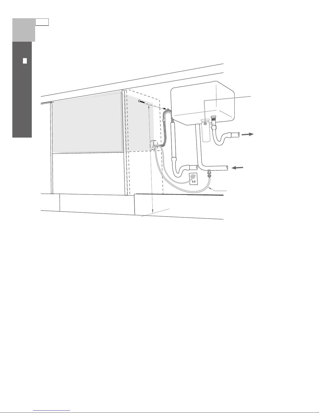
Plumbing and drainage - OPTION 1 (connection)
3
2
1
2
3
1
4
29 ½” - 34 ¾”
(750 -
882.5 mm)
DishDrawer® with Waste Disposal
If space is limited
for fixing, push hose
through drain hose
support to required
height
9
10
Fit supplied
washer
Ensure hoses are routed
straight to joiner. Remove
excess hose material if
necessary.
24
SINGLE MODELS
US CA
DishDrawer® using Air Break with Drain Hose Joiner
Plumbing and drainage - OPTION 2
Waste
Valve
Water
supply
(HOT)
min. R 8 ”
(
200 mm)
Supplied drain
hose joiner
(
ø
¾
” (19 mm))
waste tee)
Air Break
37 ⁄” (950 mm)
Max. height to
top of Air Break
(countertop or
wall mounted)
25
SINGLE MODELS
US CA
Plumbing and drainage - OPTION 2 (connection)
1
3
2
1
4
DishDrawer® using Air Break with Drain Hose Joiner
9
10
Ensure hoses are routed
straight to joiner. Remove
excess hose material if
necessary.
Fit supplied
washer
26
SINGLE MODELS
US CA
DishDrawer® and Standpipe Ø
1 ½ ”
(38 mm)
Plumbing and drainage - OPTION 3
29 ½ ” - 34 ¾ ”
(
750 - 882.5 mm)
Waste
Waste
Valve
Water
supply
(HOT)
min. R 8 ” (200 mm)
Waste disposal
(optional)
 Loading...