

DCS DCS-VH-48S, DCS-VH-48HS, DCS-VH-36HS, DCS-VH12-36HS, DCS-VH12-36S Use And Installation Manual
...
_Oynamic _ _yot_, _nc.
Thank you for selecting this DCS ProfessionalVent Hood. Because of its unique features, we have developed this
Use and Installation Guide.It contains valuable information on how to properly operate and maintain your new
Vent Hood for years of safe and enjoyable cooking.
Tohelp serve you better, please fitt out and return the Ownership Registration Card and keep this guide handy,
as it wilt help answer questions that may arise as you useyour New Vent Hood.
For your convenience,product questions can be answered by a DCS Customer Service
Representative by phone: 1-888-281-5698, or Fax: 714-372-7003,
or by mail:
DCS
Attention Customer Service,
5800 Skylab Road,Huntington Beach,CA 92647
WARNING
Toreduce the risk of electrical shock or injury to persons all Vent Hoods must be installed with ventilators that
have been approved for use with the hood. SeeTableA of this instruction manual for a listing of approved
ventilators.
PRECAUTION
Do Not store or usegasoline or any other flammable vapors and liquids in the vicinity of this or any other
appliance.
PLEASE RETAIN THIS MANUAL
FOR FUTURE REFERENCE.
INTRODUCTION:
The DCSVent Hood Models have been designed with the ultimate in household convenience in mind.
Features include High Capacity, Variable Speed Blower, Commercial Style dishwasher-safe filters, Easy-
to-Clean inside liner, and Illuminating Halogen Lighting, all packaged in a stylish, welded-seam exterior.
Before proceeding with installation, please read this installation guide and observe all safety precautions
and warnings.
NOTE: Installation of this DCSVent Hood must comply with all local codes.
IHPORTANT- Savethese instructions for the Local Electrical Inspector's use.
INSTALLER- Leave these instructions with the unit for the owner.
SAFETY PRACTICES & PRECAUTIONS ...............................................................................3
PLANNING THE INSTALLATION ..............................................................................................4
INNER LINER REMOVAL ..................................................................................................................4
VENT HOOD ASSEMBLY .................................................................................................................S
VENT HOOD INSTALLATION (WITH SOFFIT) .........................................................6-7
VENT HOOD INSTALLATION (WITHOUT SOFFIT) .................................................8
FINISHING THE INSTALLATION ...............................................................................................9
DUCT INFORMATION ....................................................................................................................10
DCSVH SERIES SPECIFICATIONS .........................................................................................I
HOWTO OBTAIN SERVICE ........................................................................................................12
WARRANTY ............................................................................................................................................13
WIRING DIAGRAM ......................................................................................................................N-IS
O WARNING: To reduce the risk of a range top grease fire:
A) Never leave surface units unattended at high se_ings. Boilovers cause smoldng and greasy
spillovers that may ignite. Heat oil slowly on low or medium settings.
B) Always turn hood"ON" when cooldng at high heat or when cooldng flaming foods.
C) Clean ventilating fans frequently. Grease should not be allowed to accumulate on fan or filter.
D) Use proper pan size. Always use cookware appropriate for the size of the surface element.
Make-Up air may be necessary to prevent air flowing down chimney, unsealed door, window, or fireplace
opening.
WARNING: To reduce the risk of fire, electrical shock, or injury to persons, observe the following
guidelines.
A) Installation and Electrical Wiring Must Be Performed By Qualified Personnel In Accordance With All
Applicable Codes & Standards, Including Fire-Rated Construction.
B) To Prevent Backdrafting, sufficient air is needed to maintain proper combustion and safe exhausting
of gases through the flue (chimney) of fuel burning equipment. Follow the cooking equipment
manufacturers guideline and safety standards such as those published by the National Fire
Protection Association (NFPA) and the American Society for Heating, Refrigeration and Air
Conditioning Engineers (ASHRAE), and the local code authorities.
C) Use caution when cutting or drilling into walls or ceilings as not to damage electrical wiring and
other hidden utilities.
CAUTION:To Reduce the risk of fire and to properly exhaust air, be sure to duct air to outside. -do not
vent exhaust air into spaceswithin walls or ceiling, nor into attics, crawl spaces,or garages.
NOTE: unit MUST be vented to the outside of the building.
WARNING:To reduce the risk of electrical shock or injury to persons, all vent hoods must be installed
with ventilators that have been approved for use with the hood.
Ventilator Use:
TABLE A:
Vent Hood Model
DCS-VH-48HS
DCS-VH-48S
DCS-VH12-36HS
DCS-VH12-36S
DCS-VH-36HS
DCS-VH-36S
DCS-VH-30HS
DCS-VH-30S
use with Ventilator Model
DCS-IBI2 (1200 CFM)
DCS-IBI2 (1200 CFM)
DCS-IBI2 (1200 CFM)
DCS-IBI2 (1200 CFM)
DCS-IB6 (600 CFM)
DCS-IB6 (600 CFM)
DCS-IB6 (600 CFM)
DCS-IB6 (600 CFM)
*AII Ventilator Models used
in DCS Professional Vent
Hoods are approved by
Underwriters Laboratory
BACKDRAFT DAHPER:
We recommend that a backdraft damper be used in all Vent Hood installations. Cold weather installa-
tions necessitate the use of a backdraft damper to minimize the flow of cold air into the room. A non-
metallic thermal break should also be installed to minimize conduction of outside temperatures
through the ductwork. Locate the thermal break as close as possible to where the ducting enters the
heated portion of the house.
PLANNING THE INSTALLATION:
Before beginning installation of theVent Hood andVentilator, PLAN OUT the entire installation proce-
dure beforehand, considering the following areas:
I. HOOD SIZE & LOCATION- (The hood should be as wide or wider than the cooldng appliance with
the hood being centered on the appliance.Vertically, the bottom of the hood should be between 30"-
36" above the appliance cooldng surface).
2. DUCTING- (ducting transitions, air flows to outside? Use of Backdraft damper? ...etc.)
3. ELECTRICAL REQUIREMENTS- ( 120Volts, 60 Hz, 15 AMP Service, Local Codes...etc.)
4.ADEQUATE MOUNTING SURFACES- (location of wall studs, additional support for safe wall
mounting...etc.)
0 HANDLING NOTE- This Hood has been inspected prior to shipping to be free of defects. Due to the
weight of the Vent Hood and Ventilator and to prevent scratching or denting the unit, we recommend the use of
two installers to move,place, and secure the Vent Hood to avoid personal injury or damage to the Hood.
INNER LINER REHOVAL:
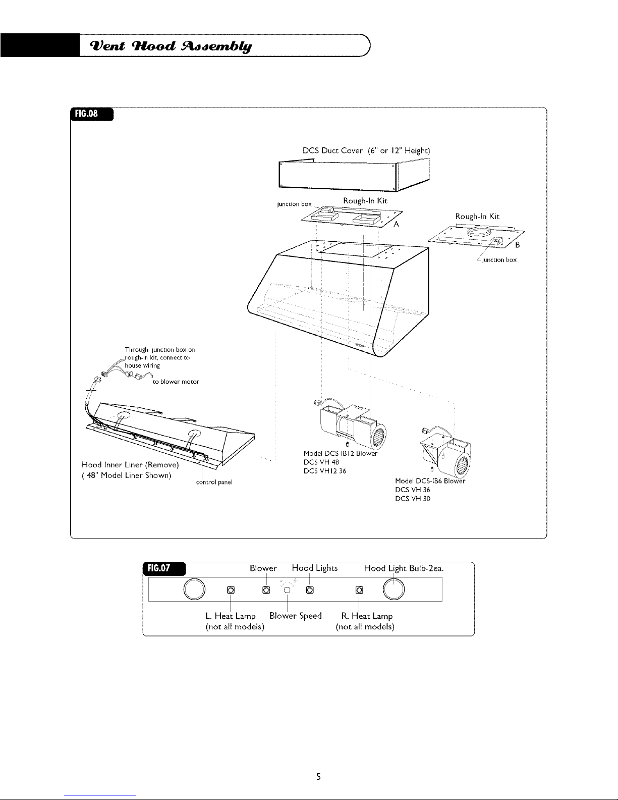
The DCS Professional Vent Hood has been designed into (2) major assemblies to accommodate easy
and safe installation. The following procedure is best done with the Hood on its back on a padded sur-
face. The inside liner assembly can be separated from the outer hood assembly by removing the (I 2)
inner perimeter screws- (3 each side/front/back). Once these screws have been removed, the liner
assembly can slide down to gain access to the male/female disconnect plug- See Fig.8 on page 5.After
the disconnect plug has been unplugged, the liner assembly can be set aside until the hood has been
installed into the soffit or wall.
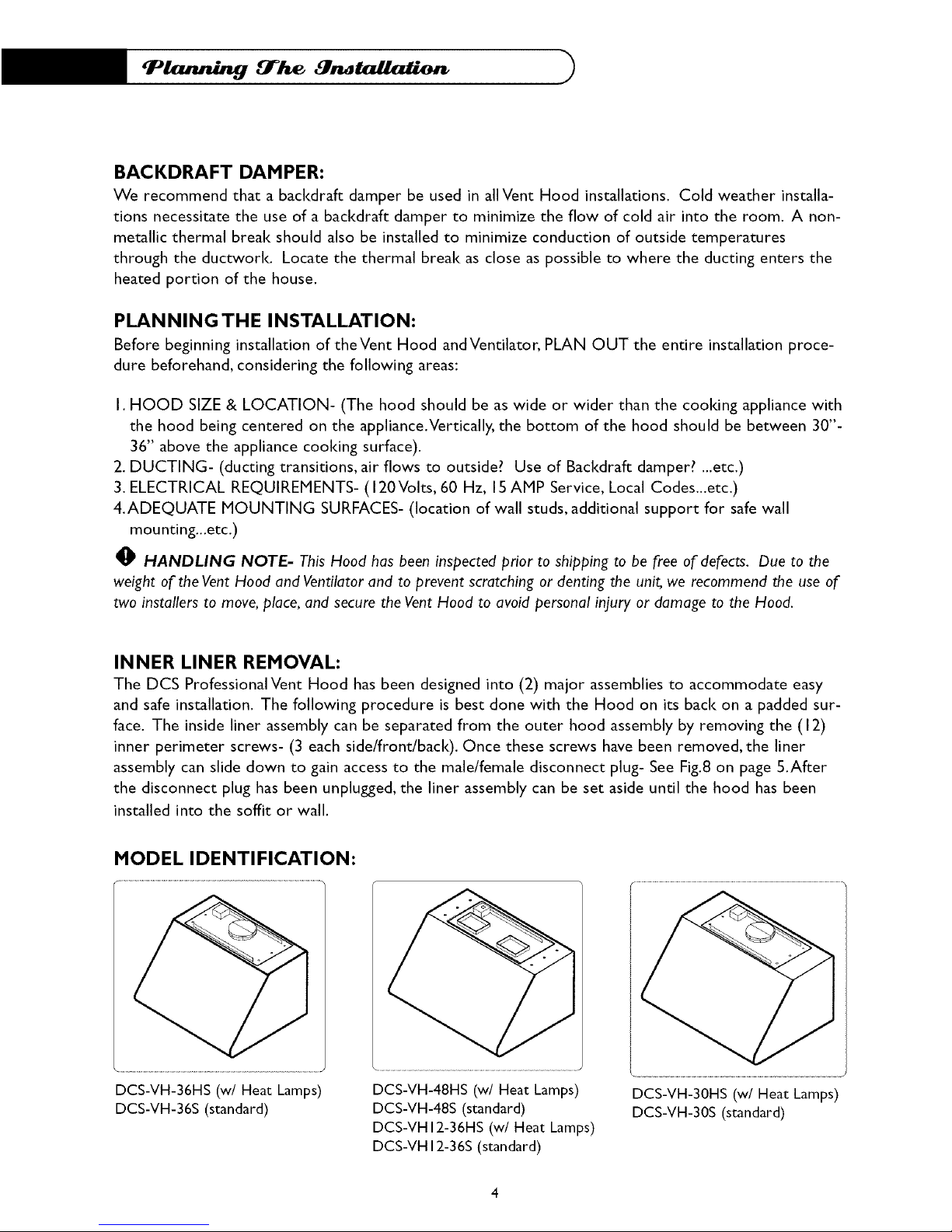
HODEL IDENTIFICATION:
DCS-VH-36HS (w/Heat Lamps)
DCS-VH-36S (standard)
DCS-VH-48HS (w/Heat Lamps)
DCS-VH-48S (standard)
DCS-VHI2-36HS (w/Heat Lamps)
DCS-VH 12-36S(standard)
DCS-VH-30HS (w/Heat Lamps)
DCS-VH-30S (standard)
Id[_(i][;!
DCS Duct Cover (6" or 12" Height)
junctionbox Rough-In Kit
Rough-In Kit
• junction box
Through junction box on
rough-in kit, connect to
house wiring
_ to blower motor
ii
control panel
Model DCS-IB 12 Blower
DCS VH 48
DCS VH 12 36
Model -_
DCSVH 36
DCSVH 30
Blower Hood Lights Hood_t Bulb-2ea.[] [] o [] []
I d[_ly_
L. Heat Lamp Blower Speed R. Heat Lamp
(not all models) (not all models)
 Loading...