

Page 1

Dynamic Cooking S ystems, Inc.
ISLAND VENT HOOD
Care and Use Installation Instructions
Models:
■
DCS-IVH-48
■
DCS-IVH-36
Page 2

1
Thank you for selecting this DCS Professional Island Vent Hood. Because of this appliance’s unique features we
have developed this Installation and Use Guide. It contains valuable information on how to properly operate and
maintain your new appliance for years of safe and enjoyable use.
To help serve you better, please fill out and return the Ownership Registration Card and keep this Guide handy,
as it will help answer questions that may arise as you use your new vent hood.
For your convenience, product questions can be answered by a
DCS Technical Support Representative by phone:
1-888-281-5698 or Fax: 714-372-7003
or by mail:
DCS
Attention Customer Service,
5800 Skylab Road, Huntington Beach, CA 92647
Before proceeding with installation, please read this installation guide and observe all safety precautions
and warnings.
NOTE: Installation of this DCS Island Vent Hood must comply with all local codes.
IMPORTANT: Save these instructions for the Local Electrical Inspector’s use.
INSTALLER: Please leave these instructions with the unit for the owner.
OWNER: Please retain these instructions for future reference.
Mes sag e To Our Customers
Page 3

2
Tab le of Contents
IMPORTANT SAFETY INSTRUCTIONS . . . . . . . . . . . . . . . . . . . . . . . . . . . . . . . . . . . . . . . . . . . . . . . . .3
FEATURES . . . . . . . . . . . . . . . . . . . . . . . . . . . . . . . . . . . . . . . . . . . . . . . . . . . . . . . . . . . . . . . . . . . . . . . . . . . . . . . . . . .4
PLANNING THE INSTALLATION . . . . . . . . . . . . . . . . . . . . . . . . . . . . . . . . . . . . . . . . . . . . . . . . . . . . . . . . . . . . . .5
SPECIFICATIONS. . . . . . . . . . . . . . . . . . . . . . . . . . . . . . . . . . . . . . . . . . . . . . . . . . . . . . . . . . . . . . . . . . . . . . . . . . .6
SITE PREPARATION AND INSTALLATION GUIDELINES . . . . . . . . . . . . . . . . . . . . . . . . . . . .7
SOFFIT INSTALLATION . . . . . . . . . . . . . . . . . . . . . . . . . . . . . . . . . . . . . . . . . . . . . . . . . . . . . . . . . . . . . . .8-10
DUCTING INFORMATION . . . . . . . . . . . . . . . . . . . . . . . . . . . . . . . . . . . . . . . . . . . . . . . . . . . . . . . . . . . . . .11
CARE AND USE . . . . . . . . . . . . . . . . . . . . . . . . . . . . . . . . . . . . . . . . . . . . . . . . . . . . . . . . . . . . . . . . . . . . . . . .12-13
WIRING DIAGRAM . . . . . . . . . . . . . . . . . . . . . . . . . . . . . . . . . . . . . . . . . . . . . . . . . . . . . . . . . . . . . . . . . . . . . . .14
WARRANTY INFORMATION . . . . . . . . . . . . . . . . . . . . . . . . . . . . . . . . . . . . . . . . . . . . . . . . . . . . . . . . . . . .15
SERVICE . . . . . . . . . . . . . . . . . . . . . . . . . . . . . . . . . . . . . . . . . . . . . . . . . . . . . . . . . . . . . . . . . . . . . . . . . . . . . . . . . . . .16
Page 4

3
Important Safety Instructions
WARNING:To reduce the risk of a range top grease fire:
A) Never leave surface units unattended at high settings. Boilovers cause smoking and greasy
spillovers that may ignite. Heat oil slowly on low or medium settings.
B) Always turn hood “ON” when cooking at high heat or when cooking flaming foods.
C) Clean ventilating fans frequently. Grease should not be allowed to accumulate on fan or filter.
D) Use proper pan size. Always use cookware appropriate for the size of the surface element.
Make-Up air may be necessary to prevent air flowing down chimney, unsealed door, window, or fireplace
opening.
WARNING:To reduce the risk of fire, electrical shock, or injury to persons, observe the following
guidelines.
A) Installation and electrical wiring must be performed by qualified personnel in accordance
with all applicable codes & standards, including fire-rated construction.
B) To Prevent Backdrafting, sufficient air is needed to maintain proper combustion and safe
exhausting of gases through the flue (chimney) of fuel burning equipment. Follow the cooking
equipment manufacturers guideline and safety standards such as those published by the
National Fire Protection Association (NFPA) and the American Society for Heating,
Refrigeration and Air Conditioning Engineers (ASHRAE), and the local code authorities.
C) Use caution when cutting or drilling into walls or ceilings as not to damage electrical wiring
and other hidden utilities.
CAUTION: To Reduce the risk of fire and to properly exhaust air, be sure to duct air to outside. -do
not vent exhaust air into spaces within walls or ceiling, nor into attics, crawl spaces, or
garages.
NOTE: Unit MUST be vented to the outside of the building.
IMPORTANT: Refer to ducting information supplied on Pg. 11
Page 5
4
Features
ISLAND VENT HOODS DCS-IVH-48 & DCS-IVH-36
The DCS Island Vent Hood Models: DCS-IVH-48 , DCS-IVH-36, have been designed with the ultimate in
household convenience in mind.
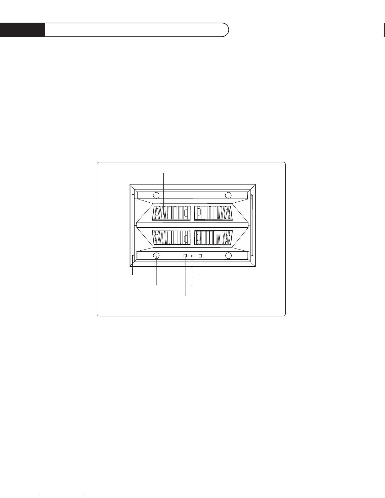
Features include a high capacity, variable speed blower with speed controller, commercial style
dishwasher-safe filters, easy to clean inside grease trays and four halogen lights with Hi/Low light switch.
(4)
halogen
lights
light on/off switch
blower variable speed control
blower on/off switch
removable washable filters
hanger rods
Page 6

5
Planning the Installation
BACKDRAFT DAMPER
We recommend that a backdraft damper be used in all Vent Hood installations. Cold weather installations necessitate the use of a backdraft damper to minimize the flow of cold air into the room.A
non-metallic thermal break should also be installed to minimize conduction of outside temperatures
through the ductwork. Locate the thermal break as close as possible to where the ducting enters the
heated portion of the house.
PLANNING THE INSTALLATION
Before beginning installation of the Island Vent Hood and Ventilator, PLAN OUT the entire installation
procedure beforehand, considering the following areas:
• HOOD SIZE & LOCATION- (The hood should be as wide or wider than the cooking
appliance with the hood being centered on the appliance.Vertically, the bottom of the hood
should be between 30”-36” above the appliance cooking surface.)
• DUCTING- (ducting transitions, air must flow to outside, use of Backdraft damper...etc.)
• ELECTRICAL REQUIREMENTS- (120 Volts, 60 Hz, 15 AMP Service, Local Codes...etc.)
• ADEQUATE MOUNTING SURFACES- (To support the weight of the vent hoods, location of
ceiling studs, additional support for safe ceiling mounting...etc.)
HANDLING NOTE: This Hood has been inspected prior to shipping to be free of defects. due to the
weight of the Island Vent Hood and Ventilator; and to prevent scratching or
denting the unit, we recommend the use of two installers to move, place, and
secure the Vent Hood to avoid personal injury or damage to the Hood.
Page 7
6
Specifications
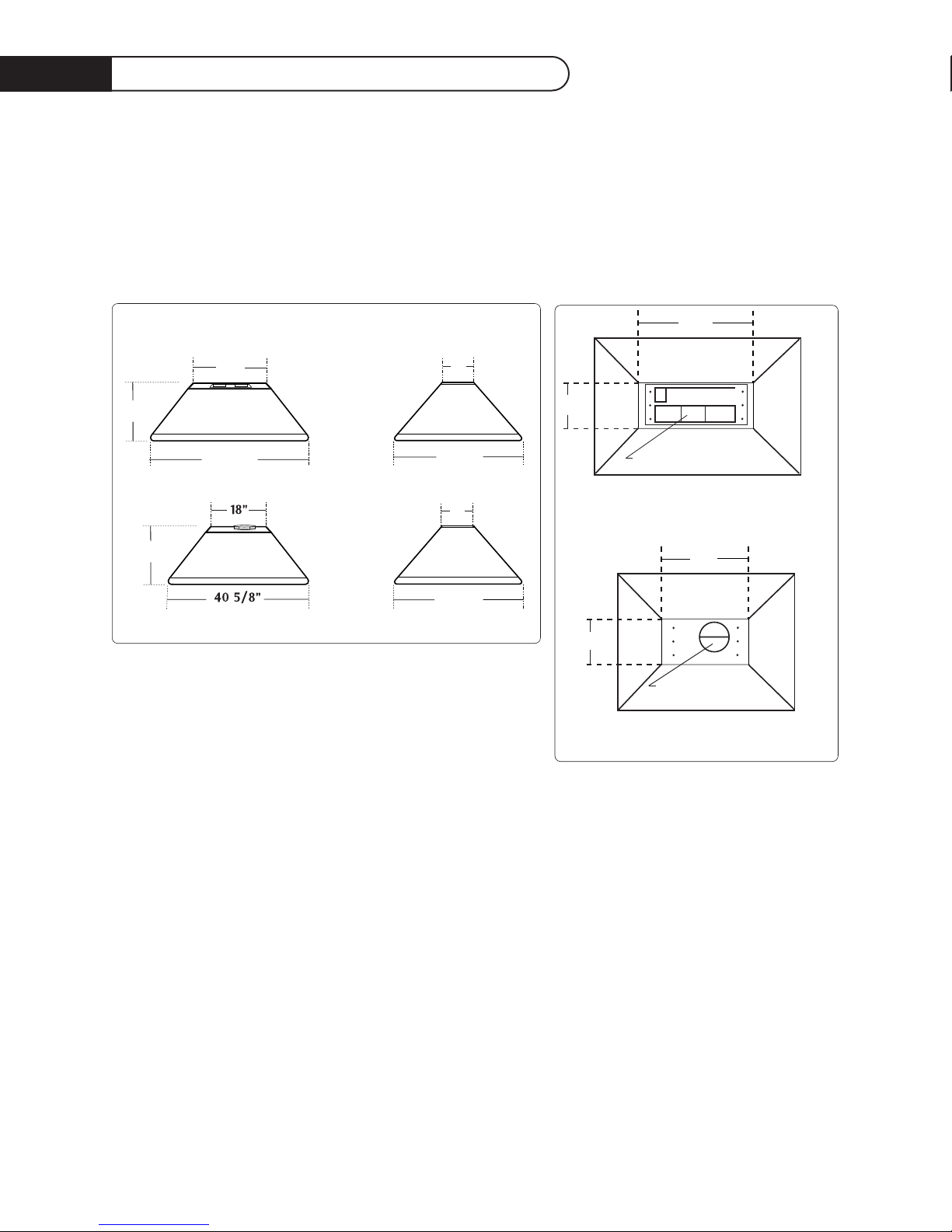
PRODUCT AND VENTING SPECIFICATIONS
Refer to venting specifications below when ordering the duct transition to 10” Ø for 36” Island Vent
Hood.
See Page 11 for
Ducting Information.
30"
12"
TOP VIEW of DCS-IVH-48
18"
12"
TOP VIEW of DCS-IVH-36
venting specs 7" Ø
venting specs 4"x18" rectangular
16"
52 5/8"
30"
16"
FRONT VIEW
SIDE VIEW
34 5/8"
12"
12"
34 5/8"
DCS-IVH-48
DCS-IVH-48
DCS-IVH-36
DCS-IVH-36
VENT HOOD DIMENSIONS
Page 8

7
Site Preparation and I nstallation G uidelines
SITE PREPARATION
You will need to create a secure soffit structure to mount the Island Vent Hood to the ceiling.We
suggest using 1 1/2” by 3 1/2“ wood cut to fit the installation as shown in the following pages.The soffit
mounting to the top of the Island Vent Hood will be 10 7/8“ in length for the DCS-IVH-48 and 10 3/4“
for the DCS-IVH-36.These dimensions allow room for a 1/2 drywall duct cover. Do not deviate from
these dimensions when choosing a duct cover as the soffit structure must align with the mounting
holes on the Island Vent Hood.You are limited to a maximum of 1/2 inch on all sides.
NOTE: You will need to determine which type of duct cover will be used before installation and leave
enough space around the soffit for a flush mount between the duct cover material and the top
of the Island Vent Hood.
CAUTION: When installing the ISLAND VENT HOOD directly to the ceiling, adequate structural
supports are critical to secure the unit.The Island Vent Hood is heavy, weighing 128 LBS for
the DCS-IVH-48 and 94 LBS for the DCS-IVH-36.
NOTE: The soffit height will vary according to the ceiling height.
GENERAL INSTALLATION GUIDELINES:
1) Determine the location for installation.
2) Determine the centerline of the installation.
3) If drywall is installed, cut away enough drywall to expose 2 ceiling joist (1 on each side of the
Hood center line)
4) Create your soffit structure according to ceiling height and attach soffit plates for DCS-IVH-36
or soffit brackets for DCS-IVH-48 with screws to sides (see the following pages for soffits and
construction).
5) Attach soffit structure to existing ceiling joist.
6) Secure soffit with soffit braces according to model type (see diagrams page 8-10).
7) Attach Island Vent Hood to soffit with the six 2 inch mounting screws provided.
FINISHING THE INSTALLATION:
Once the Island Vent Hood has been mounted in place it will be necessary to install the electrical
service. All electrical work should be done by a qualified electrician and must conform to all local
standards. Refer to the wiring diagram on Pg. 14 for proper hook-up and grounding.
NOTE: Black=live, White=neutral, Green=ground
Complete the installation by making ductwork connections, testing unit functions, and installing
& finishing drywall.
Page 9
8
Soffit Installation
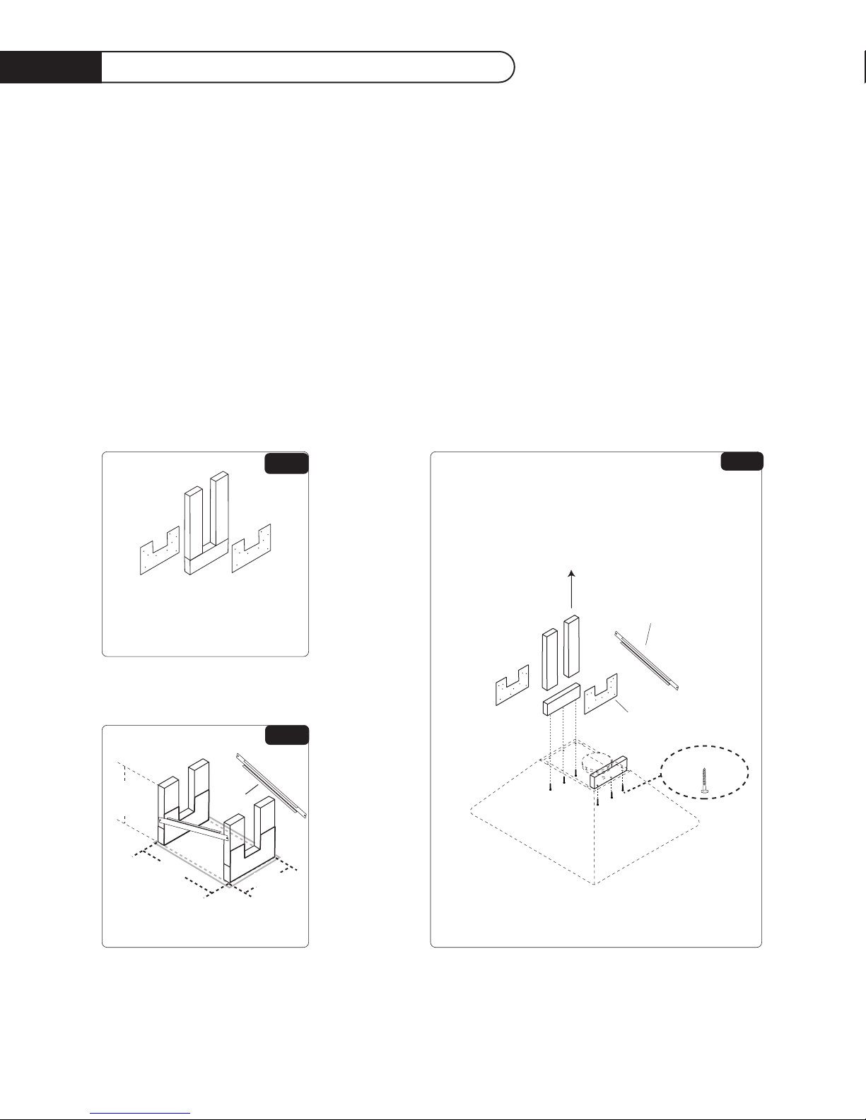
SOFFIT FOR DCS-IVH-36 ISLAND VENT HOOD
The dimensions given are for a 1/2 inch drywall.
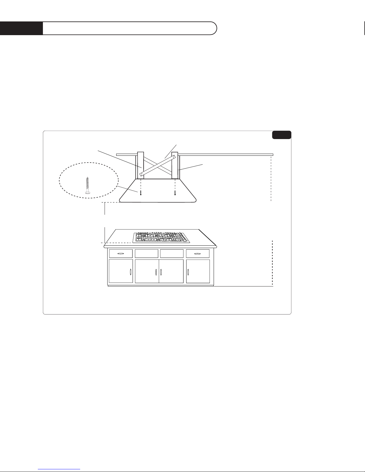
1) Create a soffit structure and attach the soffit brackets as in figure 1. Refer to the installation
guidelines on Page 7.
2) Attach the soffit support bars as shown in figure 2.
3) After securing the soffit structure adequately to the ceiling joist, attach the Island Vent Hood
with the mounting screws provided, figure 3.
Refer to page 7 on finishing the installation.
36" ISLAND VENT HOOD SOFFIT MOUNTING
6 Mounting Screws
SOFFIT BRACKETS
SCREWED TO BOTH SIDES
OF SOFFIT STRUCTURE
SCREW SUPPORT BARS
ON BOTH SIDES AS SHOWN
CREATE YOUR
SOFFIT STRUCTURE
ACCORDING TO THE
CEILING HEIGHT
THEN ATTACH IT
TO THE CEILING JOIST.
Create your Soffit Structures
first and attach Soffit Brackets
to each side with screws provided
FIG.3
FIG.1
SUPPORT
BARS
SOFFIT ASSEMBLY
FOR 36" ISLAND VENT HOOD
10 3/4 "
HEIGHT WILL
VARY
ACCORDING
TO CEILING
HEIGHT
16 3/4 "
The dimensions given
are for a 1/2 " drywall.
FIG.2
Page 10
9
Soffit Installation
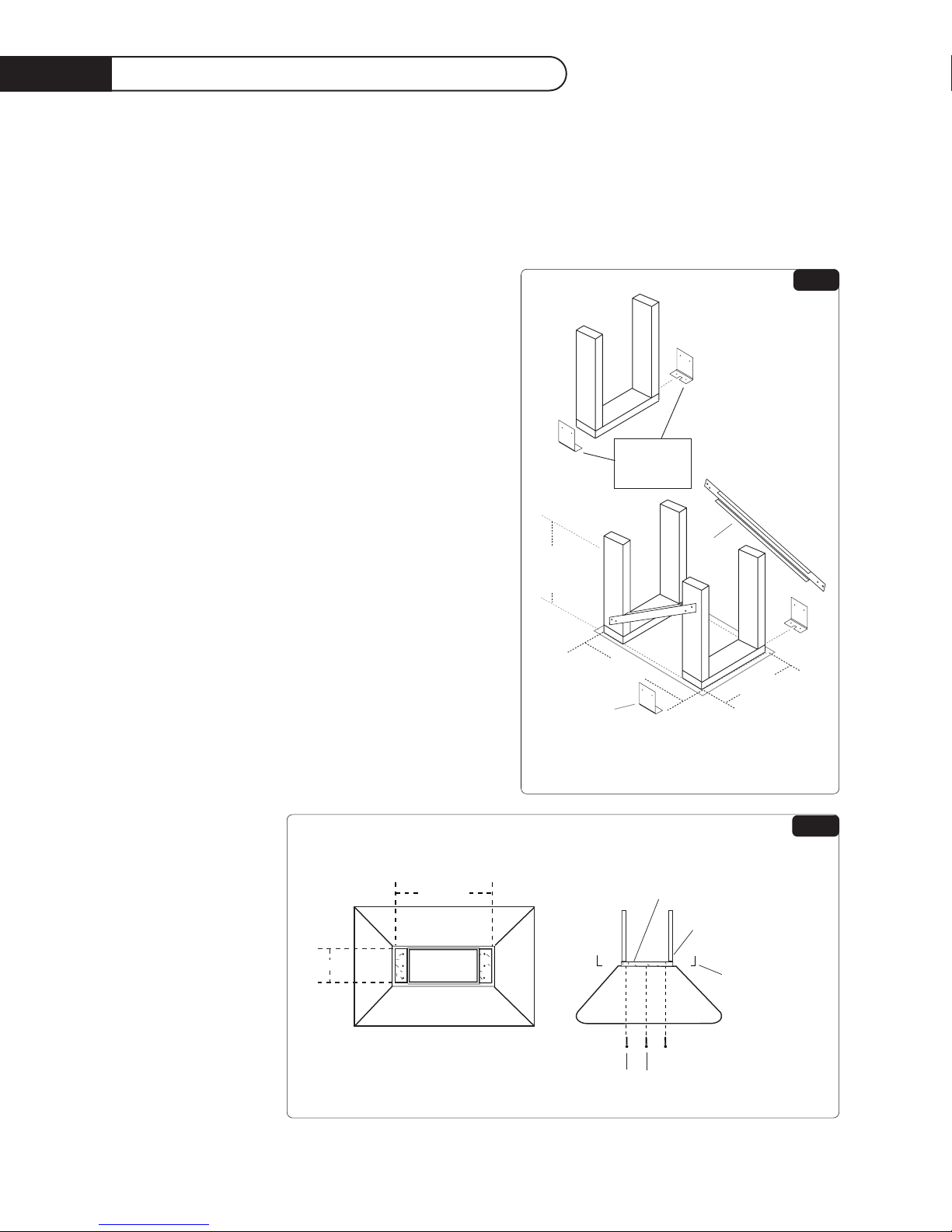
SOFFIT FOR DCS-IVH-48 ISLAND VENT HOOD
The dimensions given are for a 1/2 inch drywall duct cover.
1) Create a soffit structure and attach the soffit brackets as illustrated in figure 1. Refer to the
installation guidelines on Page 7.
2) Attach the soffit support bars as shown in figure 4.
3) After adequately securing the soffit structure to
the ceiling joist, attach the Island Vent Hood with
the 6 mounting screws provided, figures 5 and 6
show the location of the mounting screws.
Figure 5 gives soffit dimensions allowing for a 1/2 inch
duct cover.
ATTA CH SOFFIT
BRACKETS
ON 4 CORNERS
OF THE
SOFFIT STRUCTURE
2 SUPPORT
BARS
SOFFIT ASSEMBLY
FOR DCS-IVH-48
10
7
/
8
"
HEIGHT WILL
VARY
ACCORDING
TO CEILING
HEIGHT
28
7
/
8
"
4 SOFFIT
BRACKETS
The dimensions given are for a 1/2 " drywall.
FIG.4
28 7/8"
10 7/8"
TOP VIEW of DCS-IVH-48
SIDE VIEW for DCS-IVH-48 SOFFIT STRUCTURE
1 1/2" x 31/2" Soffit
3 1/2"centerline
to centerline measurement
from screw to screw
Wood Structure
1
1/2" x 31/2" Soffit
(4) soffit
brackets
The dimensions given are for a 1/2 " drywall.
FIG.5B
Page 11
10
Soffit Installation
DIAGRAMS FOR DCS-IVH-48 ISLAND VENT HOOD
The dimensions given are for a 1/2 inch drywall duct cover.
Figure 6 below illustrates a finished soffit structure for the DCS-IVH-48
Refer to page 7 on finishing the installation.
counter top level
FRONT VIEW of DCS-IVH-48
30" Min.
to cooking surface
Support Bars
Ceiling
Floor
Typical 96"
Ceiling Shown
Duct Cover
NOTE: Duct
Cover height
will vary according
to ceiling height
these must be
custom built.
6 Mounting Screws
Solid Soffit Structure
mounted to ceiling joices
FIG.6B
Page 12

11
Ducting I nformation
GENERAL
When planning the path for ducting to the outside, keep in mind the following guidelines:
• Minimize use of elbows and transitions in ductwork as to maximize air flow to outside of
building.An efficient airflow path contributes to the overall efficiency of the Vent Hood.
• DCS recommends the use of “smooth wall” ducting, not flexible ductwork.
• Transitions are required from rectangular to round ducting.
(see transitions as shown below)
• Duct tape may be used at ducting joints.
DCS-IVH-48 REQUIREMENTS
• DCS recommends the use of 10” round ducting which provides 78.6 In.2of surface area.
• See Duct Accessories below on for ratio to 10” transition.
• Alternate duct sizes in rectangular style may be used. If a rectangular duct style is used, the duct
must equal at least 78.6 In.
2
for best results. (Example- 3 1/4”x 24” duct = 78 In.2)
• Maintain consistent ducting square area as to avoid reduced air flow. [ie.- With a ivh-48 Hood,
connecting a 4”x13” (52 In.
2
) to a 10”round (78.6 In.2) is not recommended]
DCS-IVH-36 REQUIREMENTS
• DCS recommends the use of 7” round ducting which provides 34.7 In.2of surface area.
• Alternate duct sizes in rectangular style may be used. If a rectangular duct style is used, the duct
must equal at least 34.7 In.
2
for best results
DUCT ACCESSORIES
• Wall Caps and Roof Caps must have free open area equal to duct size diameter.
• Note that a Sealed Back Draft Damper may reduce air delivery.
• Transition for right, left or rear air discharge also available.
10"
10
1
/2"
4
5
/8"
Vertical Duct Transition for 48" Island Vent Hood
18
5
/8"
11"
Page 13

12
Care And Use
CONTROLS
We recommend you turn your hood on before you begin cooking to establish fresh airflow.After you
have finished cooking, let the blower run for a few minutes to clear the air and help keep the kitchen
fresh and clean.
BLOWER
The Blower is operated with 2 controls.The switch adjacent to the speed control turns the blower
on/off, while the speed control adjusts the blower speed.Turn the speed knob clockwise to increase
and counterclockwise to decrease the blower speed.
HOOD LIGHTING
A single switch controls the 4 halogen lights.The switch controls the brightness of the lights with
Hi/Off/Low. Use only 50w Max. Halogen Narrow Flood replacement bulbs.
CAUTION: Halogen lamps are constructed of a glass bulb with a pressurized internal filament tube
that operates at high temperatures and could be discharged into the fixture enclosure
and/or surrounding environment, thereby creating a risk of personal injury of fire.When
replacing the bulb, let the bulb cool, and assure that power to light has been turned off.
Never allow a hot bulb to come into contact with water.
Do Not Touch the Hood Light Bulbs when they are in use.They may be hot enough to cause injury.
Blower
Blower Variable Speed Control
Hood Lights
Halogen Light Bulb
Page 14

13
Care And Use
CLEANING THE EXTERIOR STAINLESS STEEL FINISH:
When cool the appliance can be cleaned with hot soapy water, rinsed, dried and buffed to a shine with
a soft, heavy pile cloth.Always try this first, as it is the mildest form of cleaning.
1. Some brands of cleaners are harsher than others. Read their instructions.Try on a small
inconspicuous area first.
2. To avoid marring the surface always rub metal finishes in the direction of the polish lines.The
cleaner will be more effective when used in the direction of the polish lines.
3. Use only clean sponges, soft cloths, paper towels, plastic non-metal soap pads for cleaning or
scouring, use only soap pads with soap still in them, a dry pad can scratch the surface.
4. Be sure to rinse thoroughly and to wipe dry to avoid water marks.
FILTERS AND GREASE TRAYS
Filters should be cleaned frequently in a detergent solution and are dishwasher safe. Empty grease
collection tray(s) regularly.
Unplug the Blower Motor before cleaning Ventilator.
• Remove filters to access blower motor plug.Vacuum blower
to clean.
• Do not immerse in water.
• Do not allow and excessive accumulation of grease.
• Use a mild detergent when cleaning.
• Do not use harsh abrasives, steel wool pads, or abrasive
cloths.
CLEANING THE GREASE TRAY
Remove filter(s) by gently pulling up and out.The grease trays can
easily be reached once the filters are removed. Grease collection
trays are easily accessible at the center beneath the filter. See
illustration below for location.
Location of grease trays
DCS-IVH-36
DCS-IVH-48
FILTERS
GREASE TRAY
Page 15

14
Wiring D iagram
DCS-IVH-48 & DCS-IVH-36 ISLAND VENT HOOD
Page 16

15
Warranty
LENGTH OF WARRANTY
One (1) Year Full parts and labor covers the entire product
Five (5) Years Limited switches and motor
DCS WILL COVER:
All repair labor and parts found to be defective due to materials or workmanship for one full year from
date of purchase. Service must be provided by an Authorized Factory Service Agent during normal
working hours.
DCS WILL NOT COVER:
• Installation or start-up
• General maintenance
• Shipping damage
• Service by an unauthorized agency
• Damage or repairs due to service by an unauthorized agency or the use of unauthorized parts.
• Service during other than normal working hours
• Improper installation, such as improper hook-up, etc.
• Service visit to teach you how to use the appliance; correct the installation; reset circuit breakers
or replace home fuses
• Repairs due to other than normal household use.
•Damage caused from accident, abuse, alteration, misuse, incorrect installation or installation not
in accordance with local codes
• Units installed in non-residential application such as day care centers, bed and breakfast centers,
churches, nursing homes, restaurants, hotels, schools, etc.
This warranty applies to vent hoods used in residential applications; it does not cover their use in
commercial situations.
This warranty is for products purchased and retained in the 50 states of the U.S.A., the District of
Columbia and Canada.This warranty applies even if you should move during the warranty period.
Should the appliance be sold by the original purchaser during the warranty period, the new owner
continues to be protected until the expiration date of the original purchaser’s warranty period.
This warranty gives you specific legal rights.You may also have other rights which vary from state to
state.
Page 17

16
Service
HOW TO OBTAIN SERVICE:
For warranty service, contact DCS Customer Service at (888) 281-5698.
Before you call, please have the following information ready:
• Model Number
• Serial Number
• Date of installation
• A brief description of the problem
Your satisfaction is of the utmost importance to us. If a problem cannot be resolved to your
satisfaction, please write or fax us at:
Write:
DCS
Attention: Consumer Relations
5800 Skylab Road
Huntington Beach, CA 92647
Fax us at: (714) 372-7003
Page 18

Dynamic Cooking S ystems, Inc.
HOTTE À ÉVACUATION ISLAND
ENTRETIEN ET UTILISATION
INSTRUCTIONS DE MONTAGE
Modèles:
■
DCS-IVH-48
■
DCS-IVH-36
Page 19

1
Nous vous remercions d'avoir choisi cette hotte à évacuation professionnelle Island de DCS Systems. Nous
avons conçu ce Manuel d'utilisation et d'installation pour expliquer ses fonctions uniques. Il contient des
informations extrêmement utiles sur la façon de faire fonctionner et d'entretenir correctement votre nouvel
appareil.Vous pourrez ainsi en profiter pendant des années en toute sécurité.
Aidez-nous à mieux vous servir en remplissant la Carte d’enregistrement du propriétaire et en nous la
renvoyant. Gardez ce manuel à portée de main afin de trouver rapidement réponse à vos questions durant l’utilisation de votre nouvelle hotte.
Si vous avez des questions au sujet de notre produit, communiquez avec un
représentant du support technique DCS par téléphone :
1-888-281-5698, ou par télécopieur : 714-372-7003,
ou par courrier :
DCS
Attention: Customer Service,
5800 Skylab Road, Huntington Beach, CA 92647
Avant de poursuive l’installation, veuillez lire ce manuel d’installation et respecter toutes les mesures de
précaution et consignes de sécurité.
REMARQUE : L’installation de cette hotte à évacuation Island DCS doit être conforme aux codes en
vigueur.
IMPORTANT : Conservez ces instructions à l’usage de votre inspecteur des installations électriques.
INSTALLATEUR : Veuillez laisser ces instructions au propriétaire de l’appareil.
PROPRIÉTAIRE : Veuillez conserver ces instructions à titre de référence.
À L’Intention De Nos Clients
Page 20

2
Ta b l e Des Matières
IMPORTANTES CONSIGNES DE SÉCURITÉ . . . . . . . . . . . . . . . . . . . . . . . . . . . . . . . . . . . . . . . . . . . . . . . . . . . . . . . . . . . . .3
CARACTÉRISTIQUES . . . . . . . . . . . . . . . . . . . . . . . . . . . . . . . . . . . . . . . . . . . . . . . . . . . . . . . . . . . . . . . . . . . . . . . . . . . . . . . . . . . . . . . . . . . . .4
PLANIFICATION DE L’INSTALLATION . . . . . . . . . . . . . . . . . . . . . . . . . . . . . . . . . . . . . . . . . . . . . . . . . . . . . . . . . . . . . . . . . . . .5
CARACTÉRISTIQUES . . . . . . . . . . . . . . . . . . . . . . . . . . . . . . . . . . . . . . . . . . . . . . . . . . . . . . . . . . . . . . . . . . . . . . . . . . . . . . . . . . . . . . . . . . . . .6
PRÉPARATION DU SITE ET CONSIGNES D’INSTALLATION . . . . . . . . . . . . . . . . . . . . . . . . . . . . . . . . . . . . .7
INSTALLATION DU SOFFITE . . . . . . . . . . . . . . . . . . . . . . . . . . . . . . . . . . . . . . . . . . . . . . . . . . . . . . . . . . . . . . . . . . . . . . . . . . . . .8-10
INFORMATIONS SUR LES CONDUITS . . . . . . . . . . . . . . . . . . . . . . . . . . . . . . . . . . . . . . . . . . . . . . . . . . . . . . . . . . . . . . . . . . .11
ENTRETIEN ET UTILISATION . . . . . . . . . . . . . . . . . . . . . . . . . . . . . . . . . . . . . . . . . . . . . . . . . . . . . . . . . . . . . . . . . . . . . . . . . .12-13
SCHÉMA DE CÂBLAGE . . . . . . . . . . . . . . . . . . . . . . . . . . . . . . . . . . . . . . . . . . . . . . . . . . . . . . . . . . . . . . . . . . . . . . . . . . . . . . . . . . . . . . . . .14
INFORMATIONS RELATIVES À LA GARANTIE . . . . . . . . . . . . . . . . . . . . . . . . . . . . . . . . . . . . . . . . . . . . . . . . . . . . . . .15
SERVICE . . . . . . . . . . . . . . . . . . . . . . . . . . . . . . . . . . . . . . . . . . . . . . . . . . . . . . . . . . . . . . . . . . . . . . . . . . . . . . . . . . . . . . . . . . . . . . . . . . . . . . . . . . . . . .16
Page 21

3
Importantes Consig nes De Sécurité
AVERTISSEMENT : Pour réduire les risques de feu de graisse dans une cuisinière :
A) Ne laissez jamais les plaques de cuisson sur réglage élevé sans surveillance. L’ébullition peut
provoquer des débordements graisseux pleins de fumée pouvant prendre feu. Chauffez l’huile
entement, à feu doux ou moyen.
B) Allumez toujours la hotte lorsque vous cuisinez à feu vif ou avec des aliments flambants.
C) Nettoyez les ventilateurs fréquemment. Ne laissez pas s’accumuler la graisse sur les ventilateurs
ou les filtres.
D) Utilisez toujours des récipients de taille appropriée aux dimensions des plaques de cuisson.
Il peut s'avérer nécessaire d’assurer de l’air d'appoint pour empêcher l’air de s’écouler dans une
cheminée, une porte ou fenêtre non hermétique ou l’ouverture d’un foyer.
AVERTISSEMENT : Pour réduire les risques d'incendie, d'électrocution et de blessures, respectez les
consignes suivantes
A) L’installation et le câblage électrique doivent être effectués conformément aux codes et normes
en vigueur, y compris les constructions classées résistant au feu.
B) Pour éviter le refoulement d'air, une quantité d’air suffisante est nécessaire pour assurer une
bonne combustion et l’évacuation des gaz à travers le carneau (cheminée) de l’appareil à gaz.
Suivez les consignes du fabricant de l’appareil de cuisson ainsi que les normes de sécurité
comme celles publiées par la National Fire Protection Association (NFPA) et la American
Society for Heating, Refrigeration and Air Conditioning Engineers (ASHRAE), ainsi que les
normes locales.
C) Faites preuve de prudence lorsque vous découpez ou percez des murs ou des plafonds afin de
ne pas endommager le câblage électrique et autres installations des services publics pouvant
être dissimulées.
MISE EN GARDE : Pour réduire les risques d'incendie et pour assurer une bonne évacuation de l’air,
veillez à ce que l’air soit conduit vers l’extérieur. Ne rejetez pas l’air évacué dans
les espaces entre les murs ou les plafonds, ni dans les greniers, les galeries ou les
garages.
NOTE : L’appareil DOIT évacuer l’air vers l’extérieur du bâtiment.
IMPORTANT : Reportez-vous aux informations sur les conduits à la page 11.
Page 22

4
Caractéristiques
HOTTES À ÉVACUATION ISLAND DCS-IVH-48 ET DCS-IVH-36
Les modèles d’hotte à évacuation Island DCS : DCS-IVH-48 et DCS-IVH-36 ont été conçus pour en
faire des appareils domestiques extrêmement pratiques.
Cette hotte possède les caractéristiques suivantes : haute capacité, ventilateur à vitesse variable avec
contrôleur de vitesse, filtres commerciaux lavables en lave-vaisselle, récipients à graisse faciles à
nettoyer et quatre lampes halogènes avec interrupteur d’éclairage Haut/Bas.
(4)
lampes
halogènes
interrupteur d'éclairage
contrôleur de vitesse du ventilateur variable
interrupteur marche/arrêt du ventilateur
filtres lavables amovibles
tiges de suspension
Page 23

5
Planification De L’Installation
REGISTRE ANTIREFOULEMENT
Nous recommandons l’utilisation d’un registre antirefoulement dans toutes les installations de hotte à
évacuation. Les installations dans des climats froids nécessitent l’utilisation d’un registre antirefoulement
pour minimiser le flot d’air froid dans la pièce. Un isolant thermique non métallique doit aussi être
installé pour réduire la conduction des températures extérieures à travers le système de conduits.
Placez-le à un endroit aussi proche que possible du point d’entrée du système de conduits dans la
partie chauffée de la maison.
PLANIFICATION DE L’INSTALLATION
Avant de débuter l’installation de la hotte et du ventilateur, PLANIFIEZ toutes les étapes de l’installation en tenant compte des éléments suivants :
• DIMENSION ET EMPLACEMENT DE LA HOTTE - (La hotte doit être aussi large, sinon plus,
que l’appareil de cuisson et doit être centrée sur celui-ci.Verticalement, le bas de la hotte doit
se trouver entre 76 et 91 cm (30 à –36 po) au-dessus de la surface de l’appareil de cuisson.
• SYSTÈME DE CONDUITS - (transitions entre les conduits, air évacué vers l’extérieur,
utilisation de registre antirefoulement...etc.)
• EXIGENCES ÉLECTRIQUES - (120 Volts, 60 Hz, intensité du courant de 15 A, normes en
vigueur...etc.)
• SURFACES DE MONTAGE ADÉQUATES – (Pour soutenir le poids des hottes, emplacement
des poteaux muraux, soutien additionnel pour un montage au plafond sécuritaire...etc.)
NOTE CONCERNANT LA MANIPULATION : Cette hotte a été inspectée avant expédition et est
exempte de défauts. En raison du poids de la hotte Island et du ventilateur, et pour ne pas risquer
d’égratigner ou de bosseler l’appareil, nous recommandons que deux personnes se chargent de
déplacer, installer et fixer la hotte afin d’éviter des blessures et de ne pas endommager la hotte.
Page 24

6
Caractéris tiq ues
CARACTÉRISTIQUES DU PRODUIT ET DE VENTILATION
Référez-vous aux caractéristiques de ventilation ci-dessous pour commander la transition de conduit à
10 po Ø pour la hotte Island de 36 po.
Voir la page 11 concernant les Informations sur les conduits.
30"
12"
DCS-IVH-48
VUE DE HAUT
18"
12"
DCS-IVH-36
VUE DE HAUT
Spécification de
ventilation : Ø de 18 cm (7 po)
Spécifications de ventilation :
ouverture rectangulaire de 10 x 46 cm (4 x 18 po)
16"
52 5/8"
30"
16"
VUE DE FACE
VUE LATÉRALE
34 5/8"
12"
12"
34 5/8"
DCS-IVH-48
DCS-IVH-48
DCS-IVH-36
DCS-IVH-36
DIMENSIONS DE LA HOTTE
Page 25

7
Site Consignes Pour La Préparation Du Site Et L’Installation
PRÉPARATION DU SITE
Vous devrez fabriquer un soffite pour monter la hotte au plafond. Nous vous suggérons d’utiliser du
bois mesurant 1 1/2 po x 3 1/2 po pour une installation comme celle illustrée dans les pages suivantes.
Le soffite monté sur le haut de la hotte doit mesurer 10 7/8 po de longueur pour le modèle DCS-IVH48 et 10 3/4 po pour le modèle DCS-IVH-36. Ces dimensions laissent de la place à un couvre-conduit
fait de cloison sèche de 1/2 po. Respectez ces dimensions dans le choix d’un couvre-conduit car le
soffite doit être aligné avec les trous de montage de la hotte.Vous êtes limité à 1/2 po maximum sur
tous les côtés.
REMARQUE : Vous devrez déterminer quel type de couvre-conduit sera utilisé avant de procéder à
l’installation et laisser un espace suffisant autour du soffite pour que le couvre-conduit
affleure le haut de la hotte.
MISE EN GARDE : Pour installer la hotte directement au plafond, un support structurel adéquat doit
absolument être présent pour permettre de fixer solidement l’appareil. La hotte
Island est lourde et pèse 58 kg/128 lb (modèle DCS-IVH 48) et 43 kg (modèle
DCS-IVH-36).
REMARQUE : La hauteur du soffite varie selon la hauteur du plafond.
CONSIGNES D’INSTALLATION GÉNÉRALES :
1) Déterminez le lieu de l’installation.
2) Déterminez l’axe médian de l’installation.
3) Si vous utilisez des panneaux de cloison sèche, découpez-en suffisamment pour exposer 2 solives
du plafond (1 de chaque côté de l’axe médian de la hotte).
4) Créez le soffite en fonction de la hauteur du plafond. Fixez sur les côtés, à l’aide de vis, les
plaques de soffite (modèle DCS-IVH-36) ou les supports de soffite (modèle DCS-IVH-48).Voir la
construction des soffites aux pages suivantes.
5) Fixez le soffite à la solive du plafond.
6) Retenez-le solidement à l’aide de renforts en fonction du type du modèle (voir les schémas des
pages 8 à 10).
7) Fixez la hotte Island au soffite à l’aide des six vis de fixation de 2 po fournies.
PHASE FINALE DE L'INSTALLATION :
Une fois la hotte mise en place, vous devez procéder à l’installation électrique. Celle-ci doit être
confiée à un électricien qualifié et respecter les normes en vigueur. Reportez-vous aux schéma de
câblage à la page 14 pour savoir comment entreprendre un branchement et une mise à la terre
correctes.
REMARQUE : Noir=sous tension, Blanc=neutre, Vert=terre
Pour achever l’installation, effectuez les connexions à travers les conduits, testez les
fonctions de l’appareil, posez la cloison sèche et faites-en la finition.
Page 26

8
Installation D u Sof fite
SOFFITE POUR HOTTE ISLAND MODÈLE DCS-IVH-36
LES COTES INDIQUÉES S’APPLIQUENT À UNE CLOISON SÈCHE DE 1/2 PO.
1) Fabriquez un soffite et fixez les supports de soffite tel qu’indiqué à la figure 1. Reportez-vous aux
consignes d’installation à la page 7.
2) Fixez les barres de support du soffite tel qu’indiqué à la figure 2.
3) Après avoir bien fixé le soffite à la solive du plafond, fixez la hotte à l’aide des vis de fixation
fournies.Voir figure 3.
Voir la page 7 pour terminer l’installation.
MONTAGE DU SOFFITE DE
HOTTE ISLAND MODÈLE 36 po
6 vis de fixation
SUPPORTS VISSÉS DES
DEUX CÔTÉS DU SOFFITE
VISSEZ LES BARRES DE SUPPORT DES
DEUX CÔTÉS, TEL QU'INDIQUÉ
CRÉEZ LE SOFFITE
EN FONCTION DE
LA HAUTEUR DU
PLAFOND, PUIS
FIXEZ-LE À LA
SOLIVE DU PLAFOND.
Créez d’abord le soffite, puis
fixez les supports de soffite
sur les côtés, à l'aide
des vis fournies
FIG.3
FIG.1
BARRES
DE SUPPORT
SOFFITE POUR HOTTE
ISLAND MODÈLE 36 po
10 3/4 "
LA HAUTEUR
DU SOFFITE
VARIE SELON
LA HAUTEUR
DU PLAFOND
16 3/4 "
Les cotes indiquées s’appliquent
à une cloison sèche de 1/2 po
FIG.2A
Page 27

9
SOFFITE POUR HOTTE ISLAND MODÈLE DCS-IVH-48
LES COTES INDIQUÉES S’APPLIQUENT À
UN COUVRE-CONDUIT EN CLOISON
SÈCHE DE 1/2 PO.
1) Fabriquez un soffite et fixez les supports
de soffite tel qu’indiqué à la figure 4.
Reportez-vous aux consignes d’installation à la page 7.
2) Fixez les barres de support du soffite tel
qu’indiqué à la figure 4.
3) Après avoir bien fixé le soffite à la solive
du plafond, fixez la hotte à l’aide des 6 vis
de fixation fournies. Leur emplacement
est indiqué sur les figures 5 et 6.
La figure 5 donne les cotes de soffite pour un
couvre-conduit en cloison sèche de 1/2 po.
FIXEZ LE
SUPPORT
DE SOFFITE AUX
4 COINS
DU SOFFITE
2 BARRES
DE
SUPPORT
ENSEMBLE DE SOFFITE
POUR DCS DCS-IVH-48
10
7
/
8
"
LA HAUTEUR
DU SOFFITE
VARIE SELON LA
HAUTEUR DU
PLAFOND
28
7
/
8
"
4 SUPPORTS
DE SOFFITE
Les cotes indiquées s’appliquent
à une cloison sèche de 1/2 po.
Installation D u Sof fit
FIG.4B
28 7/8"
10 7/8"
DCS-IVH-48
VUE DE HAUT
SOFFITE DE DCS-IVH-48
VUE LATÉRALE
Soffite 1 1/2 po x 3 po
3 1/2 po – mesure d’axe
médian à axe médian,
d’une vis à l’autre
Structure en bois
Soffite 1
1/2 po x 3 1/2 po
(4) supports
de soffite
Les cotes indiquées s’appliquent à une cloison sèche de 1/2 po.
FIG.5B
Page 28

10
Installation D u Sof fite
SCHÉMAS POUR HOTTE ISLAND MODÈLE DCS-IVH-48
LES COTES INDIQUÉES S’APPLIQUENT À UN COUVRE-CONDUIT EN CLOISON SÈCHE DE
1/2 POUCES.
La figure 6 ci-dessous illustre un soffite terminé pour le modèle DCS-IVH-48
Voir la page 7 pour terminer l’installation.
counter top level
DCS-IVH-48
VUE DE FACE
30 po min.
jusqu’à la surface de cuisson
Barres de support
Plafond
Plancher
Plafond
typique
de 96 po
Couvre-conduit
REMARQUE : la hauteur
du couvre-conduit
varie selon la hauteur
du plafond. Il doit être
fabriqué sur mesure.
6 vis de fixation
Soffite solide monté
aux solives du plafond
FIG.6B
Page 29

11
Informations S ur Les Conduits
GÉNÉRALITÉS
Lorsque vous planifiez la disposition des conduites menant vers l’extérieur, tenez compte des consignes
suivantes :
• Minimisez l’emploi de coudes et de transitions afin de maximiser le débit d'air vers l’extérieur du
bâtiment. Une voie de flux d'air efficiente contribue à l’efficacité globale de la hotte.
• DCS recommande l’utilisation de conduits muraux plutôt que de conduits flexibles.
• Des transitions sont requises pour connecter des conduits rectangulaires à des conduits ronds
(voir les transitions illustrées ci-dessous).
• Utilisez du ruban pour conduits pour sceller les joints de
EXIGENCES DU MODÈLE DCS-IVH-48
• DCS recommande l’utilisation de conduits ronds de 10 po fournissant une surface utile de
78,6 po
2
.
• Voir Accessoires de conduits ci-dessous pour le ratio d’une transition de 10 po.
• Des conduits rectangulaires de dimension différente peuvent être utilisés. Si vous utilisez un
conduit rectangulaire, celui-ci doit être égal à au moins 78,6 po
2
pour assurer de meilleurs
résultats. (Exemple : conduit de 3 1/4 po x 24 po = 78 po
2
)
• Assurez une surface de conduit constante afin d’éviter toute restriction de débit d'air. [Ex.- Avec
une hotte IVH-48, il n’est pas conseillé de connecter un conduit de 4 po x 13 po (52 po
2
) à un
conduit rond de 10 po (78,6 po
2
)].
EXIGENCES DU MODÈLE DCS-IVH-36
• DCS recommande l’utilisation de conduits ronds de 7 po fournissant une surface utile de
34,7 po
2
.
• Des conduits rectangulaires de dimension différente peuvent être utilisés. Si vous utilisez un
conduit rectangulaire, celui-ci doit être égal à au moins 34,7 po
2
pour assurer de meilleurs
résultats.
ACCESSOIRES POUR CONDUITS
• Les chapeaux de mur et de toit doivent posséder une zone ouverte de dimension égale au
diamètre des conduits.
• Notez qu’un registre antirefoulement scellé peut réduire le flux d’air.
• Des transitions pour évacuer l’air par la droite, la gauche ou l’arrière sont également disponibles.
10"
10
1
/2"
4
5
/8"
Transition de conduit verticale pour hotte Island modèle 48 po
18
5
/8"
11"
Page 30

12
Entretien Et Utilisation
COMMANDES
Nous vous recommandons d’allumer la hotte avant de commencer la cuisson afin d’assurer un débit
d'air frais. Une fois la cuisson terminée, laissez le ventilateur marcher pendant quelques minutes pour
purifier l’air et garder la cuisine fraîche et propre.
VENTILATEUR
Le ventilateur est contrôlé à l’aide de deux commandes. L’interrupteur adjacent au contrôle de vitesse
allume et éteint le ventilateur, alors que le contrôle de vitesse ajuste la vitesse du ventilateur.Tournez le
bouton de vitesse dans le sens horaire pour augmenter la vitesse, et le sens contraire pour la réduire.
ÉCLAIRAGE DE LA HOTTE
Un seul interrupteur contrôle les 4 lampes halogènes et peut régler leur intensité sur Hi/Off/Low
(Haut/Éteint/Bas). Utilisez uniquement des ampoules halogènes de rechange à faisceau étroit de 50 W
maximum.
MISE EN GARDE : Les lampes halogènes sont faites d'une ampoule de verre comportant un tube à
filament interne pressurisé fonctionnant à des températures élevées, créant ainsi
un risque de blessures ou d'incendie. Avant de remplacer une ampoule, laissez-la
refroidir et assurez-vous que le courant est coupé. Ne laissez jamais une ampoule
chaude entrer en contact avec l’eau.
Ne touchez pas les ampoules d’éclairage de la hotte lorsqu’elles sont allumées. Elles pourraient être
assez chaudes pour vous blesser.
Ventilateur
Contrôleur de vitesse du ventilateur variable
Éclairage de
la hotte
Ampoule halogène
Page 31

13
Entretien Et Utilisation
NETTOYAGE DE LA FINITION EN ACIER INOXYDABLE EXTÉRIEURE
Une fois refroidi, l’appareil peut être nettoyé avec de l’eau savonneuse chaude, puis rincé, séché et bien
poli à l’aide d’un tissu à poils épais et doux. Essayez cela en premier, c’est la façon la plus douce de le
nettoyer.
1. Certains produits de nettoyage sont plus durs que d’autres. Lisez leur mode d’emploi et faites-en
l’essai sur une petite surface cachée.
2. Pour ne pas gâcher la surface, frottez toujours la finition dans le sens du polissage, ce qui donne
plus d’efficacité au nettoyant.
3. Pour nettoyer ou récurer, utilisez uniquement des éponges propres, des tissus doux, des essuietout, des bichons au savon non-métalliques en plastique contenant encore du savon. Un bichon
sec peut égratigner la surface.
4. Rincez soigneusement et séchez en essuyant pour éviter de laisser des marques d’eau.
FILTRES ET RÉCIPIENTS À GRAISSE
Les filtres doivent être nettoyés fréquemment dans une solution détergente. Ils sont lavables en lavevaisselle.Videz les récipients à graisse périodiquement.
Débranchez le moteur du ventilateur avant de nettoyer le ventilateur.
• Retirez les filtres pour accéder à la prise du moteur du
ventilateur. Nettoyez le ventilateur avec un aspirateur.
• Ne l’immergez pas dans l’eau.
• Évitez toute accumulation excessive de graisse.
• Utilisez un détergent doux pour le nettoyage.
• N’utilisez pas d’abrasifs durs, de laine d'acier ou de chiffon
abrasif.
NETTOYAGE DU RÉCIPIENT À GRAISSE
Retirez les filtres en tirant doucement vers le haut, puis vers
l’extérieur. Les récipients à graisse sont facilement accessibles au
centre, sous les filtres, une fois ceux-ci retirés. Reportez-vous à
l'illustration ci-dessous pour repérer leur emplacement.
Emplacement des récipients à graisse
DCS-IVH-36
DCS-IVH-48
FILTERS
GREASE TRAY
Page 32

14
Schéma De Câblage
HOTTE À ÉVACUATION ISLAND DCS-IVH-48 ET DCS-IVH-36
Page 33

15
Informations Relatives À La Garantie
DURÉE DE LA GARANTIE
Un (1) an, pièces et main-d'œuvre sur tout le produit.
Garantie limitée de cinq (5) ans sur les interrupteurs et le moteur.
DCS COUVRE LES FRAIS SUIVANTS
Frais de main-d'œuvre et de réparation de pièces jugées défectueuses pour cause de vice de matière ou de fabrication pendant la première année d’achat. Le service doit être fourni par un agent agréé de l’usine durant les
heures ouvrables normales.
DCS NE COUVRE PAS LES FRAIS SUIVANTS :
• Installation ou démarrage
• Maintenance d’ordre général
• Dommages subis durant le transport
• Service effectué par un centre non agréé
• Dommages ou réparations causés par un service effectué par un centre non agréé ou par l’utilisation de pièces non autorisées
• Service effectué en dehors des heures ouvrables normales
• Mauvaise installation, telle qu’un branchement incorrect, etc.
• Visites de service pour vous apprendre comment utiliser l’appareil, corriger l’installation, réarmer
les disjoncteurs ou remplacer les fusibles de la maison
• Réparations dues à une utilisation autre qu'une utilisation domestique normale
• Dommages causés par accident, abus, altération, mauvaise utilisation, installation incorrecte ou
installation non conforme aux codes en vigueur
• Appareils installés dans le cadre d’applications non résidentielles telles que garderies, auberges,
églises, maisons de soin, restaurants, hôtels, écoles, etc.
Cette garantie s'applique aux hottes à évacuation utilisées dans des applications résidentielles. Elle ne
couvre pas les utilisations commerciales.
Cette garantie couvre les produits achetés et utilisés dans les 50 états des États-Unis, le District de
Columbia et le Canada. La garantie s'applique même si vous déménagez durant la période de garantie. Si
l’appareil est vendu par l’acheteur initial durant la période de garantie, le nouveau propriétaire continue
de bénéficier de la protection jusqu’à la date d'expiration de la période de garantie de l’acheteur initial.
Cette garantie vous donne des droits juridiques spécifiques. Il se peut que vous ayez d'autres droits
pouvant varier d'une juridiction à l'autre.
Page 34

16
Service
POUR L'OBTENTION DU SERVICE DE GARANTIE :
Pour le service sous garantie, appelez le service à la clientèle DCS au (888) 281-5698.
Avant d'appeler, veuillez avoir les informations suivantes à portée de main :
• Numéro de modèle
• Numéro de série
• Date d'installation
• Brève description du problème.
Votre satisfaction revêt la plus haute importance pour nous. Si un problème n'est pas résolu à votre
entière satisfaction, veuillez communiquer avec nous par courrier ou télécopieur :
Écrivez-nous à l'adresse suivante :
DCS
Attention: Consumer Relations
5800 Skylab Road
Huntington Beach, CA 92647
Faxez-nous au numéro suivant : (714) 372-7003
AVANT D'APPELER LE SERVICE TECHNIQUE :
1. Est-ce que le disjoncteur s'est déclenché ou que le fusible est grillé?
2.Y a-t-il une coupure de courant dans le secteur?
DCS améliore constamment ses produits et se réserve le droit de modifier les spécifications
ou la conception de ses produits sans aucun préavis.
Page 35

5800 Skylab Road, Huntington Beach, CA 92647
Tel: (714) 372-7000 Fax: (714) 372-7001
Customer Service: (888) 281-5698
www.dcsappliances.com
As product improvement
is an ongoing process at
DCS, we reserve the right
to change specifications
or design without notice.
Part No. 10843 Rev. 3
Litho in USA 9/2001
 Loading...