

Page 1
IMPORTANT INFORMATION
THIS SHEET IS TO BE REFERRED TO INSTEAD OF PAGE 8 IN THE SUPPLIED MANUAL
INSTALLATION
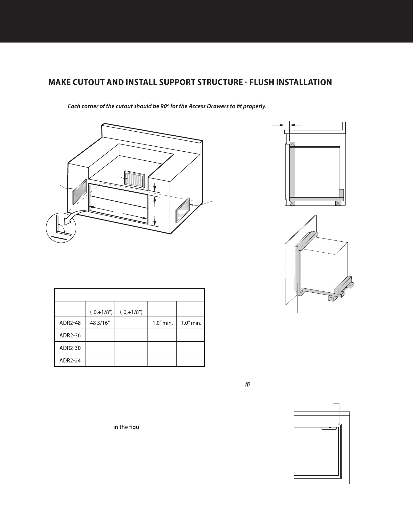
1. Make a cut-out in your cabinet or island with the following dimensions:
NOTE:
2 - 5/8” (67 mm)
D
Vent*
Vent*
C
Vent*
A
B
90º
* Island installation to use minimum of 3 vents
providing 10 sq. in. per vent (typical).
CUTOUT DIMENSIONS
Model
A
36 3/16” 1.0” min. 1.0” min.
30 3/16” 1.0” min. 1.0” min.
24 3/16” 1.0” min. 1.0” min.
B
22-1/16”
22-1/16”
22-1/16”
22-1/16”
C D
Fig. 3B
A frame should be constructed 2” (51 mm)
setback from the front face of the product
to both push the product up against and
conceal the cutout clearance around the front
frame.
Important!
Do not seal the product in with silicone caulk or
similiar. Doing so will result in the product being
di
cult to remove for servicing.
2. Place 3” X 4”s to provide support for the Access Drawers structure
in the locations indicated re opposite (Fig. 4B).
3. Board lengths are provided in the table opposite (Fig. 5B).
Note: The frame should locate the Access Drawer assembly in the
center of the cutout, and be fastened to the enclosure such that the
unit is reliably secured in place.
8
Minimum 3/16” (4 mm) cutout
clearance around front frame
07.15591027A
 Loading...