

Page 1
THE PROFESSIONAL
DS, FS SERIES GRILL
Use and Care Guide
Models:
■
DCS27FS-BQ
■
DCS27FS-BQR
■
DCS36DS-BQAR
■
DCS36DS-BQR
■
DCS36DS-BQA
■
DCS48DS-BQAR
■
DCS48DS-BQR
■
DCS48DS-BQA
Dynamic Cooking S y stems, Inc.
Page 2

1
A Message To Our Customers
Thank you for selecting this DCS Professional “DS & FS” Series Grills. Because of these appliances unique
features we have developed this Use and Care Guide. It contains valuable information on how to properly
operate and maintain your new appliance for years of safe and enjoyable cooking.
To help serve you better, please fill out and return the Ownership Registration Card and keep this guide handy,
as it will help answer questions that may arise as you use your new appliance.
For your convenience, product questions can be answered by a
DCS Consumer Service Representative at 1-888-281-5698,
or by mail:
DCS
Attention Customer Service,
5800 Skylab Road, Huntington Beach, CA 92647
WARNING
Improper installation, adjustment alteration, service or maintenance can cause property damage, injury or death.
Read the installation, operating and maintenance instructions thoroughly before use, installing or servicing this
equipment. For outdoor use only.
PRECAUTION
Do Not store or use gasoline or any other flammable vapors and liquids in the vicinity of this or any other
appliance.
FOR YOUR SAFETY
If you smell gas:
1. Shut off gas to the appliance.
2. Extinguish any open flames.
3. If odor continues, immediately call your gas supplier.
PLEASE RETAIN THIS MANUAL
FOR FUTURE REFERENCE.
Page 3

2
Tab l e O f Contents
SAFETY PRACTICES & PRECAUTIONS
...........................................................................3-4
GRILL MODELS
.......................................................................................................................................5
GAS REQUIREMENTS
....................................................................................................................6-7
LOCATING GRILL / BUILT-IN CLEARANCES
................................................................8-9
BUILT-IN CONSTRUCTION DETAILS
............................................................................10-11
LEAK TESTING
.....................................................................................................................................12
INSTALLER FINAL CHECKLIST
...............................................................................................13
BURNER ADJUSTMENTS
........................................................................................................13-14
USING THE GRILL
........................................................................................................................14-16
LIGHTING INSTRUCTIONS
.................................................................................................16-17
USING THE SMOKER SYSTEM
..................................................................................................18
USING THE ROTISERRIE BURNER
...................................................................................19-20
CARE & CLEANING
..........................................................................................................................21
BURNER REMOVAL
...........................................................................................................................22
TROUBLESHOOTING
.....................................................................................................................23
PARTS LISTS
.....................................................................................................................................24-31
Grill Burner Assembly / Parts List ............................................................................................24
Grill Body Parts List .....................................................................................................................25
Grill Body Assembly .....................................................................................................................26
Rotiserrie Assembly / Parts List ................................................................................................27
Smoker Burner Assembly / Parts List ......................................................................................28
48 Grill Cart Assembly / Parts List...........................................................................................29
36 Grill Cart Assembly / Parts List...........................................................................................30
27F Grill Cart Assembly / Parts List .......................................................................................31
SERVICE
.....................................................................................................................................................32
WARRANTY
............................................................................................................................................33
Page 4
3
Safety Practices & Precautions
IMPORTANT SAFETY NOTICE: Certain Liquid Propane dealers may fill liquid propane cylinders for
use in the grill beyond cylinder filling capacity. This “Overfilling” may create a dangerous condition.
“Overfilled” tanks can build up excess pressure. As a safety device, the tanks pressure relief valve will
vent propane gas vapor to relieve this excess pressure. This vapor is combustible and therefore can be
ignited. To reduce this danger, you should take the following safety precautions:
1. When you have your tank filled, be sure you tell the supplier to fill it to no more than 3/4 (75%) of
its total capacity.
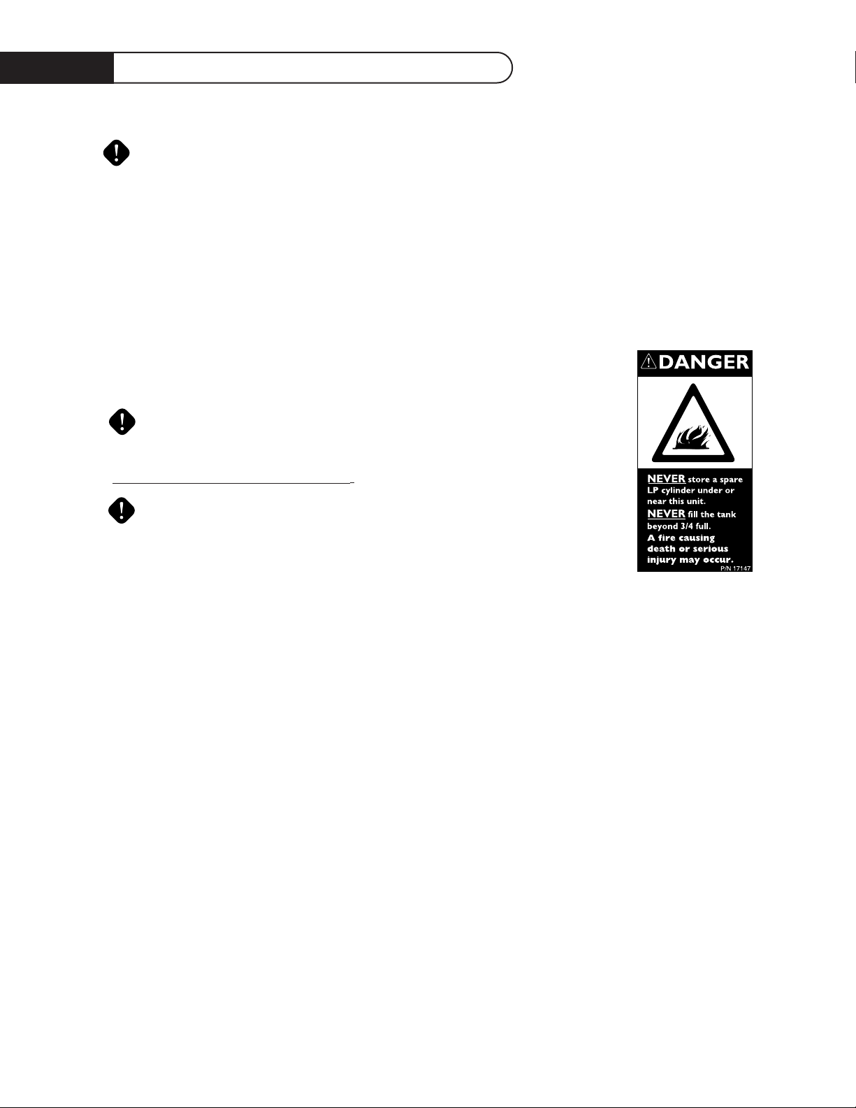
2. If you own or use an extra spare tank, or have a disconnected tank, you should NEVER store it near
or under the grill unit or heat box, or near any other ignition or heat source. A metallic sticker with
this warning is attached to the grill to remind you, your family and all others
who may use your BBQ grill of these safety precautions.
Do not remove this sticker.
WARNING: Do not try lighting this appliance without reading the “LIGHTING
INSTRUCTIONS” section of this manual.
• This Grill is f
or outdoor use only.
Children should not be left alone or unattended in an area where the grill is being
used. Never allow them to sit, stand or play on or around the grill at any time.
When in use, portions of the grill get hot enough to cause severe burns.
• Do not store items of interest to children around or below the grill, in the cart
or masonry enclosure. Never allow children to crawl inside a cart or enclosure.
•Never let clothing, pot holders or other flammable materials come in contact with or too close to
any grate, burner or hot surface until it has cooled. Fabric may ignite and result in personal injury.
• Do not heat unopened food containers as a build-up of pressure may cause the container to burst.
• Use a covered hand when opening the grill lid and only do so slowly to allow heat and steam to
escape.
•Never lean over an open grill.When lighting a burner, always pay close attention to what you are
doing. Be certain you are pushing the igniter labeled for the burner you intend on using.
• When using the grill: do not touch the grill rack, burner grate or immediate surrounding area as
these areas become extremely hot and could cause burns.
•Grease is flammable. Let hot grease cool before attempting to handle it.Avoid letting grease deposits
collect in the drip pan. Clean often.
• Do not use aluminum foil to line drip pans or grill racks.This can severely upset combustion air
flow or trap excessive heat in the control area.The result of this can be melted knobs or rotary
igniters.
• Begin by insuring proper installation and servicing. Follow the installation instructions provided with
this product. Have your grill installed by a qualified technician. Have the installer show you where the
gas supply shut off valve is located so that you know where to shut off the gas to the grill. If you
smell gas, your installer has not done a proper job of checking for leaks. If the connections are not
perfectly seated and tightened, you can have a small leak and therefore a faint gas smell. Finding a
leak is not a “do-it-yourself ” procedure. Some leaks can only be found with the burner control in
the “on” position and this must be done by a qualified technician.
Page 5

4
Safety Practices & Precautions
For personal safety, wear proper apparel. Loose fitting garments or sleeves should never be worn while
using this appliance. Some synthetic fabrics are highly flammable and should not be worn while cooking.
Only certain types of glass, heat-proof glass ceramic, earthenware, or other glazed utensils are suitable
for grill use. Use of these types of materials may break with sudden temperature changes. Use only on
low or medium heat settings according to the manufacturer’s directions.
WARNING: Spiders and insects can nest in the burners of this and any other grill, and cause the gas
to flow from the front of the burner.This is a very dangerous condition which can cause
a fire to occur behind the valve panel, thereby damaging the grill and making it unsafe
to operate.
• When using the open top burners always use flat bottomed utensils which are large enough to
cover the burner.Adjust the flame so that it heats only the bottom of the pan to avoid ignition of
clothing. Position handles inward away from open edges of the unit to avoid burns associated with
unintentional spillovers. Hold the handle of the pan to prevent movement of the utensil when
turning or stirring food. For proper lighting and performance of the burners keep the ports clean. It
is necessary to clean them periodically for optimum performance.
• Clean the grill with caution.Avoid steam burns; do not use a wet sponge or cloth to clean the grill
while it is hot. Some cleaners produce noxious fumes or can ignite if applied to a hot surface.
• Be sure all grill controls are turned off and the grill is cool before using any type of aerosol cleaner
on or around the grill.The chemical that produces the spraying action could, in the presence of
heat, ignite or cause metal parts to corrode.
• Do not use the grill for cooking excessively fatty meats or products which promote flare-ups.
•Never grill without the drip pan in place and pushed all the way to the back of the grill.Without it
hot grease could leak downward and produce a fire or explosion hazard.
• Do not operate the grill under unprotected combustible construction. Use only in well ventilated
areas. Do not use in buildings, garages, sheds, breezeway or other such enclosed areas.This unit is
for outdoor use only.
•Keep the area surrounding the grill free from combustible materials, trash, or combustible fluids and
vapors such as gasoline or charcoal lighter fluid. Do not obstruct the flow of combustion and
ventilation air.
• If a cart unit is stored indoors ensure that it is cool, fold the side shelf down, then push, never pull,
the grill. If LP, the cylinder must be unhooked and the LP cylinder stored outside in a well ventilated
area, out of reach of children.
• Do not use charcoal in the grill. Never use the grill in a windy area. Keep any electrical supply
cord, or the rotisserie motor cord away from the heated areas of the grill.
•Never use the grill in windy conditions. If located in a consistently windy area (oceanfront,
mountaintop, etc.) a wind break will be required. Always adhere to the specified clearances listed.
•Never use a dented or rusty LP tank. Keep the ventilation openings of the cylinder enclosure free
and clear from debris.
• Use only dry potholders: moist or damp potholders on hot surfaces may cause burns from steam.
Do not use a towel or bulky cloth in place of potholders. Do not let potholders touch hot portions
of the grill rack or burner grate.
• CALIFORNIA PROPOSITION 65-WARNING: The Burning of gas cooking fuel generates
some by products which are on the list of substances which are known by the State of California to
cause cancer or reproductive harm. California law requires businesses to warn customers of
potential exposure to such substances. To minimize exposure to these substances always operate
this unit according to the use and care manual, ensuring you provide good ventilation when cooking
with gas.
Page 6

5
Grill Models
R
O
T
I
S
S
E
R
I
E
DCS48DS-BQAR
DCS48DS-BQ
DCS36DS-BQAR
DCS36DS-BQR
DCS36DS-BQA
DCS27FS-BQR
DCS27FS-BQ
DCS48DS-BQR DCS48DS-BQA
Page 7

6
Gas Requirements
Verify the type of gas supply to be used, either
natural or L.P., and make sure the marking on the
appliance rating plate agrees with that of the supply.
The rating plate is located on the inside back wall
of the Grill. Never connect an unregulated gas line
to the appliance.
An installer supplied gas shut-off valve must be
installed in an easily accessible location.All installer
supplied parts must conform to local codes, or in
the absence of local codes, with the National
Electrical Code, ANSI/NFPA 70-1990, and the
National Fuel Gas Code, ANSI Z223.1-1988.
All pipe sealants must be an approved type and
resistant to the actions of L.P. gases. Never use pipe
sealant on flare fittings.All gas connections should
be made by a competent technician and in
accordance with local codes and ordinances. In the
absence of local codes, the installation must comply
with the national fuel gas code ANSI Z223.1-1988. Gas conversion kits are available from the factory.
When ordering gas conversion kits have the model number, and the type of gas (natural or L.P.) from
your grill.
TOTAL GAS CONSUMPTION OF THE GRILL WITH ALL BURNERS ON HI:
48BQRS - 124,000 BTU 48BQARS - 134,000 BTU 48BQS - 95,000 BTU 48BQAS - 120,000 BTU
36BQRS - 99,000 BTU 36BQARS - 94,000 BTU 36 BQS - 80,000 BTU 36BQAS - 80,000 BTU
27BQR - 64,000 BTU 27BQ - 50,000 BTU
The appliance and its individual shut off valve must be disconnected from the gas supply piping system
during any pressure testing of that system at test pressures in excess of 1/2 PSIG (3.5 kPa.) The
appliance must be isolated from the gas supply piping system by closing its individual manual shut-off
valve during any pressure testing of the gas supply piping system at test pressures equal to or less than
1/2 PSIG (3.5 kPa.). The installation of this appliance must conform with local codes or, in the absence
of local codes, with the national fuel gas code, ANSI Z223.1a-1988. Installation in Canada must be in
accordance with the Standard Can1-b149.1 and/or .2 (installation code for gas burning appliances and
equipment) and local codes.
NATURAL GAS HOOK UP:
Connection: 1/2" NPT male with 3/8" flare adapter. Operating pressure: 4.0" W.C.
Supply pressure: 5" to 14" water column. If in excess of 14" W.C. a step down regulator is required.
Check with your local gas utility company or with local codes for instructions on installing gas supply
lines. Be sure to check on type and size of run, and how deep to bury the line. If the gas line is too
small, the grill will not function properly. Any joint sealant used must be an approved type and be
resistive to the actions of L.P. gases.
TO HOOK-UP THE FITTINGS SUPPLIED WITH THE GRILL:
Assemble as shown (fig.01). Use threading compound on male threads only. Do not use threading
compound on the male end of the 1/2 NPT to 3/8 flare adapter. Use a second pipe wrench to hold
FIG.01 Natural Gas (36BQR Shown)
Page 8

7
Gas Requirements
the grill inlet pipe to avoid shifting any internal gas lines of the grill. Ensure that the regulator arrow
points in the direction of gas flow towards the unit, away from the supply. Do not forget to place the
installer supplied gas valve in an accessible location.
L.P. GAS HOOK UP (TYPE 1 OR QCC1 REGULATOR):
Grills orificed for use with L.P. gas come equipped with an high capacity hose/regulator assembly for
connection to a standard 20 lb. L.P. cylinder (Type 1).The L.P. tank is not included.
Connection: 1/2" NPT male with a 3/8" Flare adapter (included). LP Hose with a quick disconnect and
fittings are included. Operating pressure: 10.0"W.C.
To connect the L.P. regulator/hose assembly to the tank/valve assembly, first make sure the main valve on
the tank is completely closed. Although the flow of gas is stopped when the Type 1 system is disconnected as part of of its safety feature, you should always turn the L.P tank main valve (Fig.02) off after
each use and during transport of the tank or unit. Insert the regulator inlet into the tank valve and turn
to the black coupler clockwise until the coupler tightens up. Do not overtighten the coupler. Turn
the main tank valve on and turn the burner control valves on the unit to the “lite” position for about 20
seconds to allow the air in the system to purge before attempting to light the burners.
To disconnect the coupler, first make sure the main tank valve is turned off. Grasp the coupler and turn
counter clockwise. The inlet will then disengage, remove the inlet from the tank valve opening if it has
not already done so when it disengaged. Your local L.P. filling station should be equipped with the
proper equipment to fill your tank.
L.P.TANK REQUIREMENTS:
A dented or rusty L.P. tank may be hazardous and should be checked by your L.P. supplier. Never
use a cylinder with a damaged valve. Always check for leaks after every L.P. tank change.The L.P. gas
cylinder must be constructed and marked in accordance with the specifications for L.P. gas cylinders of the U.S.
Department of Transportation (DOT) and designed for use with a Type 1 system only. Do not change the
regulator/hose assembly from that supplied with the unit or attempt to use a 5LP-A equipped regulator/hose
assembly with a standard 510 POL tank/valve assembly. The cylinder must be provided with a shut off valve
terminating in an L.P. gas supply cylinder valve outlet specified, as applicable, for connection Type 1. If the
appliance is stored indoors the cylinder must be disconnected and removed from the appliance.
Cylinders must be stored outdoors in a well-ventilated area out of the reach of children.
FIG.02 L.P. Gas (36BQR Shown)
Page 9
8
Locating Grill/Built-In Clearances
INSULATED JACKET:
Do not build the Grill under overhead unprotected combustible construction. If the Grill is to be
placed into a combustible enclosure, an approved insulated jacket is necessary and is available from
your dealer. Use only the DCS insulated jacket which has specifically been designed and tested for this
purpose.
LOCATION:
When determining a suitable location take into account concerns such as exposure to wind, proximity
to traffic paths and keeping any gas or electrical supply lines as short as possible. Locate the grill only
in a well ventilated area. Never locate the grill in a building, garage, breezeway, shed or other such
enclosed areas without an approved ventilation system. During heavy use, the grill will produce a lot of
smoke. Ensure there is adequate area for it to dissipate.
Important : Gas fittings, regulator, and installer supplied shut-off valves must be easily accessible.
CLEARANCES TO COMBUSTIBLE CONSTRUCTION:
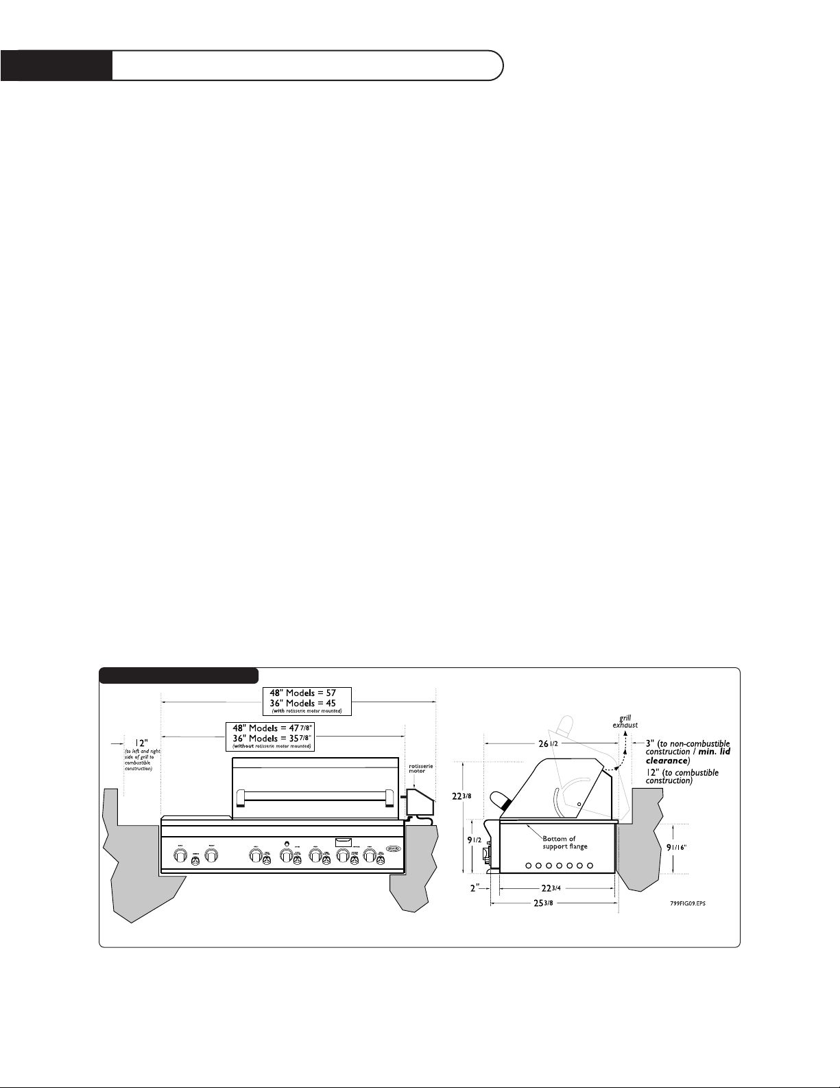
A Minimum of 12" from the sides and a minimum of 12" from the back must be maintained from the
Grill above and below the cooking surface to adjacent vertical combustible construction.
CLEARANCES TO NON-COMBUSTIBLE CONSTRUCTION:
A minimum of 3" clearance from the back of the grill to non-combustible construction is required for
the purpose of allowing the lid to open fully. It is desirable to allow at least 6" side clearance to noncombustible construction above the cooking surface for counter space. If you’ll be using the rotisserie
option, the space is essential for motor and skewer clearance.The Grill can be placed directly adjacent
to non-combustible construction below the cooking surface.
"
"
FIG.03 48DS / 36DS Models
Page 10

9
Built -I n G rill Clearances
"
FIG.03 27FS Models
GENERAL (36DS / 48DS MODELS):
The Grill is designed for easy placement into masonry enclosures. For non-combustible applications
the grill drops into the opening shown in (Fig. 05) and hangs from its side flanges. A deck is not
required to support it from the bottom.When using the insulated jacket in a combustible enclosure
application, see (Fig. 05) bottom.The jacket assembly must be supported from the bottom by a ledge
on each side or a solid deck beneath the entire grill or insulated jacket
Review the detail drawings shown and take into account the provisions shown for gas line hook-up
clearance in the left rear corner. It is recommended that ventilation holes are provided in the
enclosure in the event of a gas leak.The supporting ledges or deck must be level and flat. The counter
should also be level.
GENERAL (27FS MODELS):
The Grill is designed for easy placement into masonry enclosures. For non-combustible applications
the grill drops into the opening shown in (Fig. 06 page 10). A deck or ledge is required to support it
from the bottom.When using the insulated jacket in a combustible enclosure application, (Fig. 06 page
10) bottom. The jacket assembly must be supported from the bottom by a ledge on each side or a
solid deck beneath the entire grill or insulated jacket.
Review the detail drawings shown and take into account the provisions shown for gas line hook-up
clearance in the left rear corner. It is recommended that ventilation holes are provided in the
enclosure in the event of a gas leak. The supporting ledges or deck must be level and flat.The counter
should also be level.
Page 11

10
Built I n Cons truction D etails
FIG.05 36 / 48 Models
Page 12

11
Built I n Cons truction D etails
"
"
FIG.06 27F Models
Page 13
12
Leak Testing
GENERAL:
Although all gas connections on the grill are leak tested at the factory prior to shipment, a complete
gas tightness check must be performed at the installation site due to possible mishandling in shipment,
or excessive pressure unknowingly being applied to the unit. Periodically check the whole system for
leaks, or immediately check if the smell of gas is detected.
BEFORE TESTING:
Do not smoke while leak testing. Extinguish all open flames. Never leak test with an open
flame. Make a soap solution of one part liquid detergent and one part water. You will need a spray
bottle, brush, or rag to apply the solution to the fittings. For L.P. units, check with a full cylinder. The
valve panel must be removed to check the valves and fittings. Remove the knobs, then remove the 4
screws which fasten the valve panel to the unit (you will need a torx head for this). Pull the valve panel
outward and unplug the wires from the back of the rotary igniters. If your grill has the optional rotis
burner, remove the screws which hold the inspection cover in place.
TO TEST:
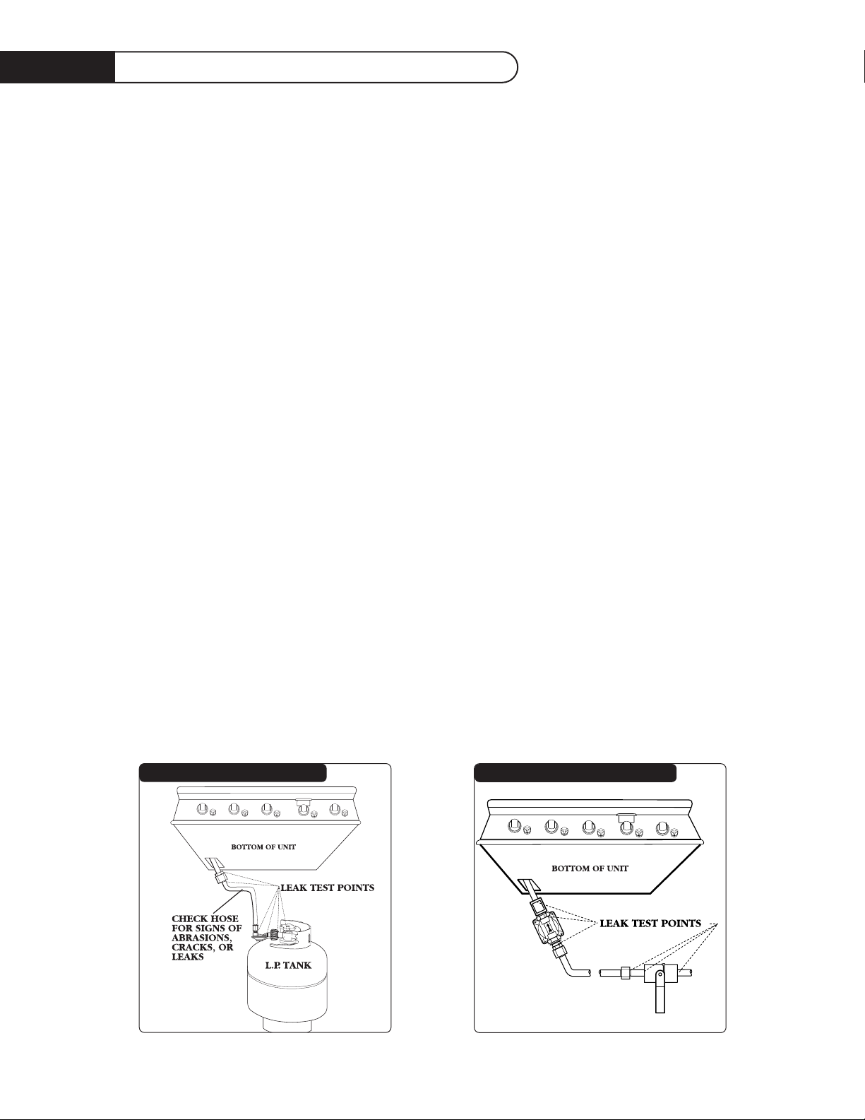
Make sure all control valves are in the “OFF” position.Turn the gas supply “ON”. Check all connections
from the supply line, or L.P. cylinder up to and including the manifold pipe assembly. Apply the soap
solution around the connection, valve and tubing. Soap bubbles will appear where a leak is present. If a
leak is present, immediately turn off gas supply, tighten any leaking fittings, turn gas on, and recheck.
Check all the gas connections at the base of the control valves where they screw into the manifold
pipe.
To check rotis burner and safety valve the burner must be lit, then leak test the connections located
under the safety cover. If you cannot stop a gas leak turn off the gas supply and call your local gas
utility, or the dealer you purchased the appliance from. Only those parts recommended by the
manufacturer should be used on the Grill. Substitution can void the warranty.
Do not use the grill until all connections have been checked and do not leak.
Check all gas supply fittings for leaks before each use. It is handy to keep a spray bottle of soapy water near
the shutoff valve of the gas supply valve. Spray all the fittings. Bubbles indicate leaks.
FIG.07 L.P. Gas
(36DS Model Shown)
FIG.08 Nat. Gas
(36DS Model Shown)
Page 14
13
INSTALLER FINAL CHECKLIST:
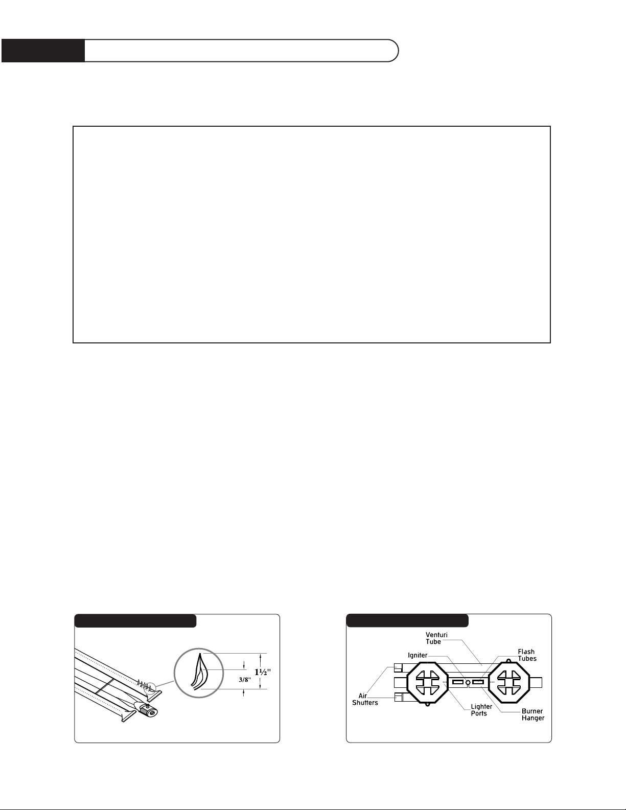
GRILL BURNER FLAME HEIGHT:
To access the grill burner air shutters first remove the valve panel by removing the four screws on the
corners of the valve panel. Remove the control knobs. Pull the valve panel outward while unplugging
the rotary igniter. With a screw driver, loosen the lock-screw on the face of the air shutter. Light the
burner and adjust according to the directions above. Access for the power burner air shutters is
through the top after removing the top burner grate (See Fig. 09).
BURNER AIR ADJUSTMENT:
Each grill burner is tested and adjusted at the factory prior to shipment; however, variations in the local
gas supply or a conversion from one gas to another may make it necessary to adjust the burners.The
flames of the burners (except the rotisserie burner) should be visually checked and compared to that
of the drawing in Fig.10 and Fig. 11. Flames should be blue and stable with no yellow tips, excessive
noise or lifting. If any of these conditions exist, check if the air shutter or burner ports are blocked by
dirt, debris, spider webs, etc. Proceed with air shutter adjustment. The amount of air which enters a
burner is governed by a sheet metal cup or disk at the inlet of the burner called an air shutter. It is
locked in place by a set screw which must be loosened prior to lighting the burner for adjustment.
❏
Specified clearances maintained to combustibles.
❏
Nylon straps removed from
burners.
❏
All internal packaging
removed.
❏
Knobs turn freely, bezels
centered.
❏
Each burner lights satisfactorily, individually or with adjacent burner lit.
❏
Air shutters adjusted.
❏
Adjustable low setting satis
factory.
❏
Drip pan in place properly
and sliding freely.
❏
Pressure regulator connected and set for 4.0"W.C.
Natural, 11.2" W.C. L.P. gas.
❏
Manual shut off valve
installed and accessible.
❏
Unit tested and free of leaks.
❏
User informed of gas supply
shut off valve location.
• PLEASE LEAVE THESE
INSTRUCTIONS WITH THE
USER.
• USER, PLEASE RETAIN
THESE INSTRUCTIONS
FOR FUTURE REFERENCE.
FIG. 09 Burner Flame Height
FIG.10 Power Burner Air Shutters
Installer Checklist / Burner Adjustments
Page 15
14
WARNING: IMPORTANT! Before lighting . . .Inspect the gas
supply piping or hose prior to turning the gas "on". If there
is evidence of cuts, wear, or abrasion, it must be replaced
prior to use.
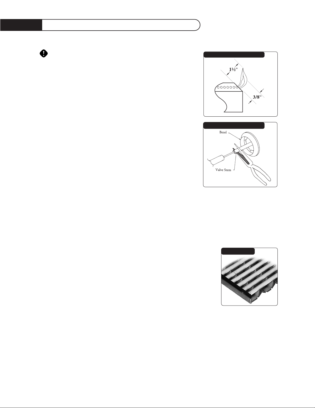
TO ADJUST:
1. Be careful as the burner may be very hot.
2. If the flame is yellow, indicating insufficient air, turn the airshutter
counterclockwise to allow more air to the burner.
3. If the flame is noisy and tends to lift away from the burner,
indicating too much air, turn the air shutter clockwise.
4. Once adjusted turn the burner off and reverse steps to
reassemble.
LOW SETTING ADJUSTMENTS:
The valves on the grill feature an adjustable low setting. Due to
fluctuations in gas pressure, heating value or gas conversion, you may
feel it necessary to increase or decrease gas flow in the low position.
We do not recommend adjusting the infra-red rotis burner.
TO ADJUST:
1. Light the burner.
2. Turn the control knob to the lowest setting (all the way counter-clockwise).
3. Remove the knob.
4. While holding the valve shaft with pliers, insert a thin, flat tipped screwdriver into the shaft and
while viewing the burner adjust to a minimum stable flame (Fig. 12).
GRILL:
Each grill section consists of a large stainless steel burner, a series of stainless
steel heat baffles, a series of ceramic tubes encased in a stainless steel rack,
and a stainless steel heat retaining cooking rack. Each burner is rated at
25,000 BTU. Below each burner is a stainless steel heat baffle which reflects
usable heat upward into the cooking area and reduces temperatures of the
drip pan below.The cast iron grill burner encompasses the entire cooking
area and is top ported to operate cooler and last longer. Above the burners
are stainless steel radiants which encase the ceramic tubes and protect the
grill burner ports from blockage. Each grill burner has its own rotary igniter.
The igniter knob is located to the immediate right of the control knob.
CERAMIC TUBES:
The Grill is supplied with radiant ceramic tubes. Because of the porosity of ceramic tubes it is
superior in its ability to capture heat as it rises from the grill burners.They also possess the thermal
mass needed for results. Flare ups are controlled because our radiant ceramic tubes keeps grease from
getting to the flames and igniting.The intense heat produced by this system produces true grilled flavor
as fats and juices are brought to the surface of the food and caramelized. Discoloration is normal
after use.
FIG.13
FIG.12 Low Setting Adjustment
Burner Adjustments /Using The Grill
Page 16

15
Us i ng The Grill
The replacement pressure regulators and hose assembly must be the type specified by the
manufacturer. Do not use the grill if the odor of gas is present.The pressure regulator and hose
assembly supplied with the unit must be used. If the unit is L.P., screw the regulator into the tank and
leak check the hose and regulator connections with a soap and water solution before operating the
grill. Turn all knobs to "off" then turn on the gas supply. If L.P., is there gas in the tank? Always keep
your face and body as far away from the grill as possible when lighting.
• DO NOT leave the grill unattended while cooking.
•Keep a spray bottle of soapy water near the gas supply valve and check the connections before
each use.
• Do not attempt to "LITE " the grill if the odor of gas is present.
•Wait 5 minutes before relighting a hot grill.
GRILLING HINTS:
The doneness of meat, whether rare, medium, or well done, is affected to a large degree by the
thickness of the cut. Expert chefs say it is impossible to have a rare doneness with a thin cut of meat.
The cooking time is affected by the kind of meat, the size and shape of the cut, the temperature of the
meat when cooking begins, and the degree of doneness desired. When defrosting meats it is
recommended that it be done overnight in the refrigerator as opposed to a microwave. This in general
yields a juicier cut of meat. Use a spatula instead of tongs or a fork to turn the meat, as a spatula will
not puncture the meat and let the juices run out. To get the juiciest meats, add seasoning or salt after
the cooking is finished and turn the meat only once (juices are lost when the meat is turned several
times). Turn the meat just after the juices begin to bubble to the surface. Trim any excess fat from the
meat before cooking. To prevent steaks or chops from curling during cooking, slit the fat around the
edges at 2-inch intervals.
Note: The hot grill sears the food, sealing in the juices. The longer the preheat, the faster the meat
browns and the darker the grill marks.
USING THE GRILL NATURAL GAS:
Grilling requires high heat for searing and proper browning. Most foods are cooked at the “MEDIUM”
heat setting for the entire cooking time. However, when grilling large pieces of meat or poultry, it may
be necessary to turn the heat to a lower setting after the initial browning. This cooks the food through
without burning the outside. Foods cooked for a long time or basted with a sugary marinade may need
a lower heat setting near the end of the cooking time.
1. Check to be certain the drip tray is in place.
2. Light the grill burners using the instructions in use and care manual.
3.With the grill lid open, turn the control knob to “HI” and preheat the grill for 15 minutes.
The grill lid is to be closed during the appliance preheat period.
4. Place the food on the grill and cook to the desired doneness.Adjust heat setting, if necessary.
The control knob may be set to any position between “HI” and “LO”.
5.Allow grill to cool and clean the drip tray after each use
Note: If using L.P. gas, your preheat time may be shorter than recommended. To prevent overcooking
or burning you may want to lower heat settings.
Page 17
16
USING THE GRILL L.P. GAS:
Grilling requires high heat for searing and proper browning. Most foods are cooked at the “Medium”
heat setting for the entire cooking time. However, when grilling large pieces of meat or poultry, it may
be necessary to turn the heat to a lower setting after the initial browning.This cooks the food through
without burning the outside. Foods cooked for a long time or basted with a sugary marinade may need a
lower heat setting near the end of the cooking time.
1. Check to be certain the drip tray is in place.
2. Light the grill burners using the instructions in use and care manual.
3.Turn the control knob to “HI”. Once the burner is lit, typical preheat time for grills using L.P.
gas is 5 to 10 minutes. The grill lid is to be closed during the appliance preheat period.
4. Place the food on the grill and cook to the desired doneness.Adjust heat setting, if necessary.
The control knob may be set to any position between “HI” and “LO”.
5.Allow grill to cool and clean the drip tray after each use
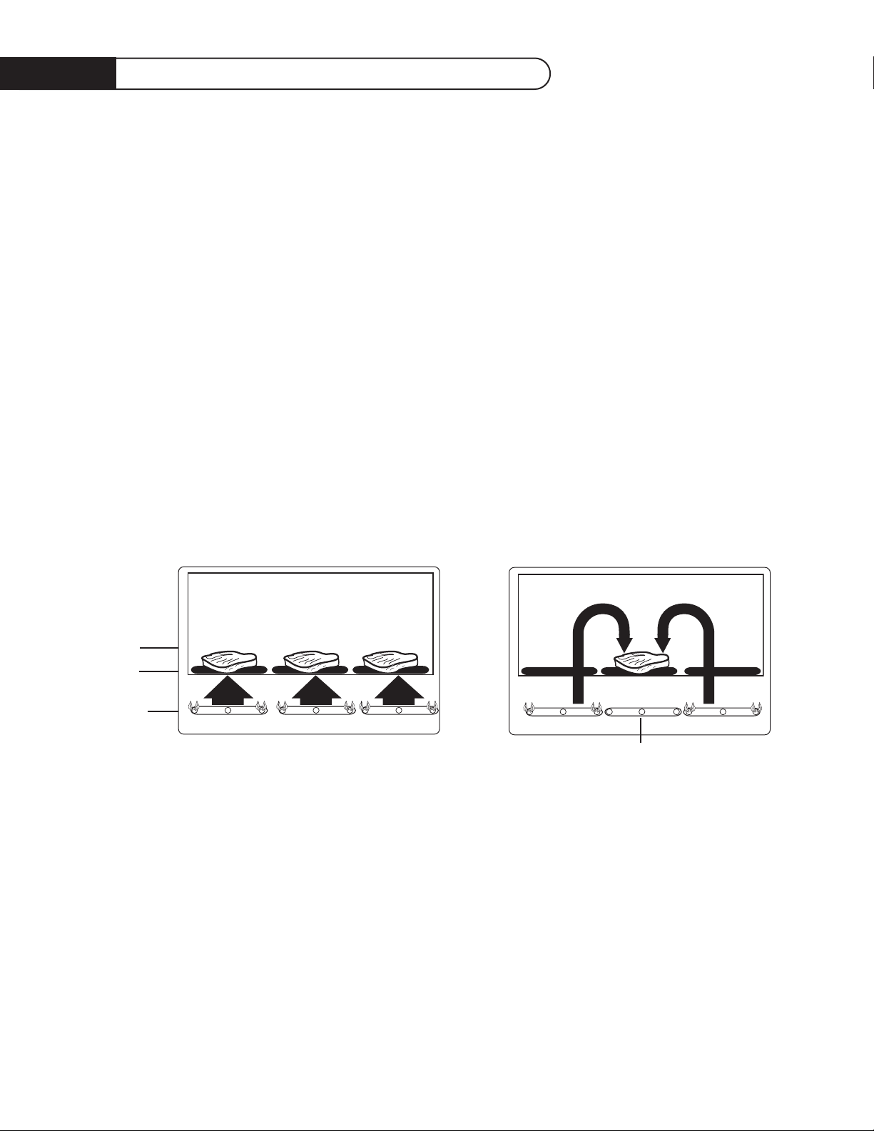
Grilling Method Note: Indirect cooking method is a popular alternative to direct heat grilling. Indirect cooking
uses heat from adjacent burners to cook food and in many cases, reduces the possibility of overcooked or overly
browned food. Foods most appropriate for indirect grilling included breads, thicker pieces of chicken or steaks.
TO LIGHT THE GRILL BURNER:
Open the lid, push and turn the control knob to the “lite” position and immediately turn the rotary
igniter knob of the spark igniter next to the burner knob.You’ll hear a snapping sound. At the same
time a spark will be provided at the grill burner. It may be necessary to turn the rotary igniter knob
several times until the burner is lit. If the burner does not light in 4 seconds, turn knobs to “off ” and
wait 5 minutes before trying again for any accumulated gas to dissipate.
MATCH LIGHTING:
If the burner will not light after several attempts then the burner can be match lit. If you’ve just
attempted to light the burner with the igniter, allow 5 minutes for any accumulated gas to dissipate.
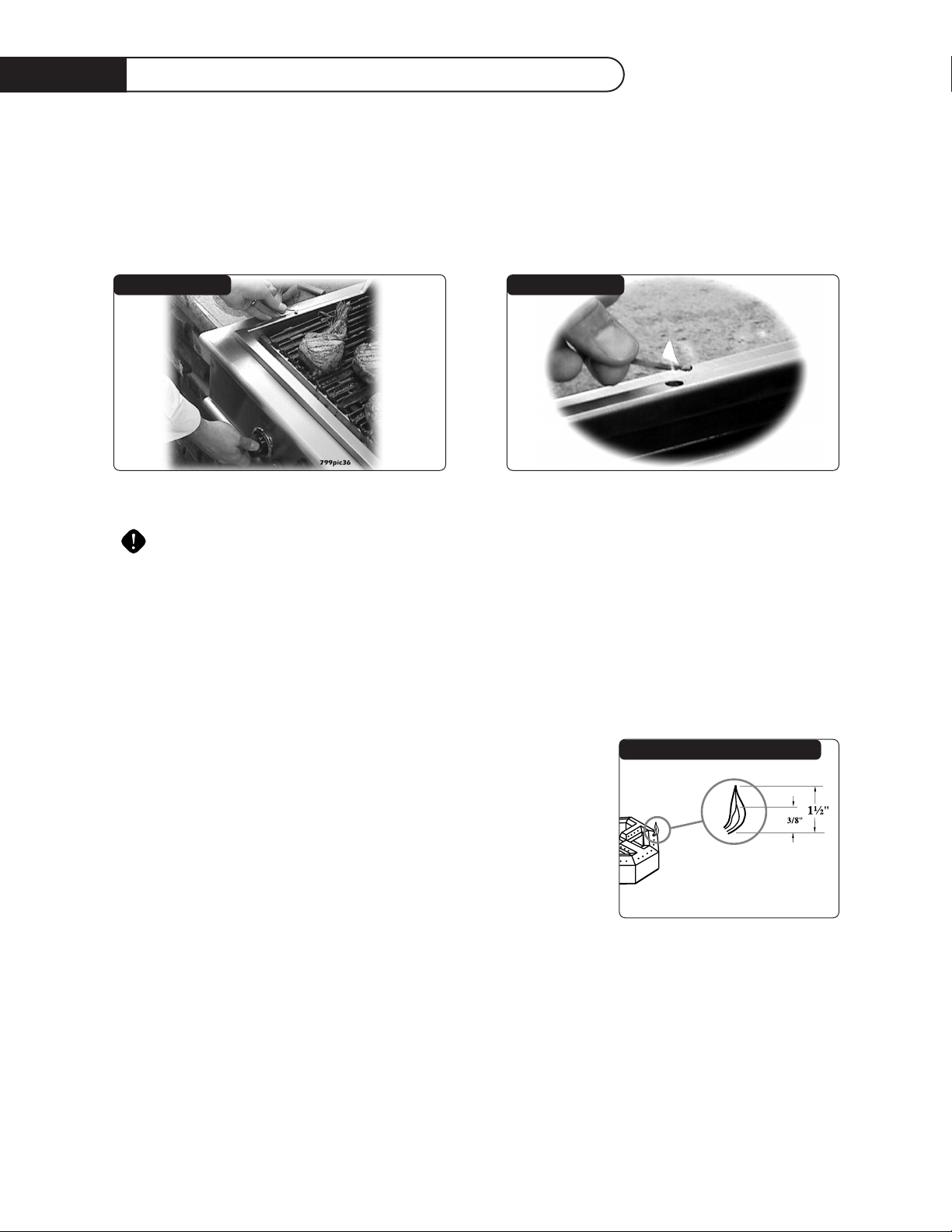
Keep your face as far away from the grill as possible and hold and pass a lit, long stem match over the
hole located on the top left for burner on the left, or the right hole for the right burner (on page 17
Fig.15). Push and turn the control knob which is centered on the burner where the lit match is located,
to “LITE”. If the burner does not light in 4 seconds turn the knob off, wait 5 minutes and try again.
Us i ng The Grill/Lighting Instructions
HEAT HEAT
Burner
Off
Indirect Heat Grilling
Food
Grill
Rack
Burner
Direct Heat Grilling
(Hot Dogs, Hamburgers,
Typical Thickness Steaks/Chicken)
HEAT HEAT HEAT
Page 18
17
Lighting / Rang etop B urner Instructions
Once the left or right burner is lit, the adjacent burner(s) can be lit by the cross-lighting method. For
center burners to cross light, light the adjacent far left or right burner using the standard or match
light procedure. Push and turn the control knob for the desired center burner to “Lite” the gas will be
ignited by the adjacent burners flame. If the burner does not light in 4 seconds, turn knob off, wait 5
minutes and try again.
SINGLE / DUAL RANGETOP BURNERS:
CAUTION:The burner cover may be hot if the grill burners are in operation.
First remove the burner cover or any cooking utensils from the burner grate. Push and turn the
control knob to the “lite” position and immediately turn the rotary igniter knob between the “Rear”
and “Front” knobs until the burner is lit or 4 seconds pass. If the burner doesn’t ignite wait 5 minutes
for any accumulated gas to dissipate then try again. If the burner will not light after several attempts,
wait 5 minutes and then the burner can be match lit by holding a lit match next to the burner ports
and turning the correct valve to “Lite”.
36/48 BQRS MODELS ONLY:
Your Grill is equipped with the same heavy cast iron burners which
we use on our line of quality restaurant ranges. Each is rated at
15,000 BTU and has a rotary spark igniter for efficient lighting. The
burner grates are porcelain enamel over cast iron for durability. To
cover the power burners when not in use, each grill comes with a
stainless steel cover which doubles as a work surface. When using the
grill burners with the work surface in place, be careful as heat can
conduct from the grill section and cause the work surface to heat up.
NEVER attempt to light the power burners with the work surface in place.
FLAME HEIGHT:
The correct height of the flame depends on the size and material of the utensil being used, the food
being cooked and how much liquid is in the utensil. Here are some basic rules for selecting the flame
height.
• The flame should never extend beyond the bottom of the pan (see Fig. 16).
• Utensils which conduct heat slowly (such as glass-ceramic) should be used with a low or
medium flame unless you are cooking with a large amount of liquid.
FIG.14 FIG.15
FIG. 16 Rangetop Burner Proper Flame
Page 19
18
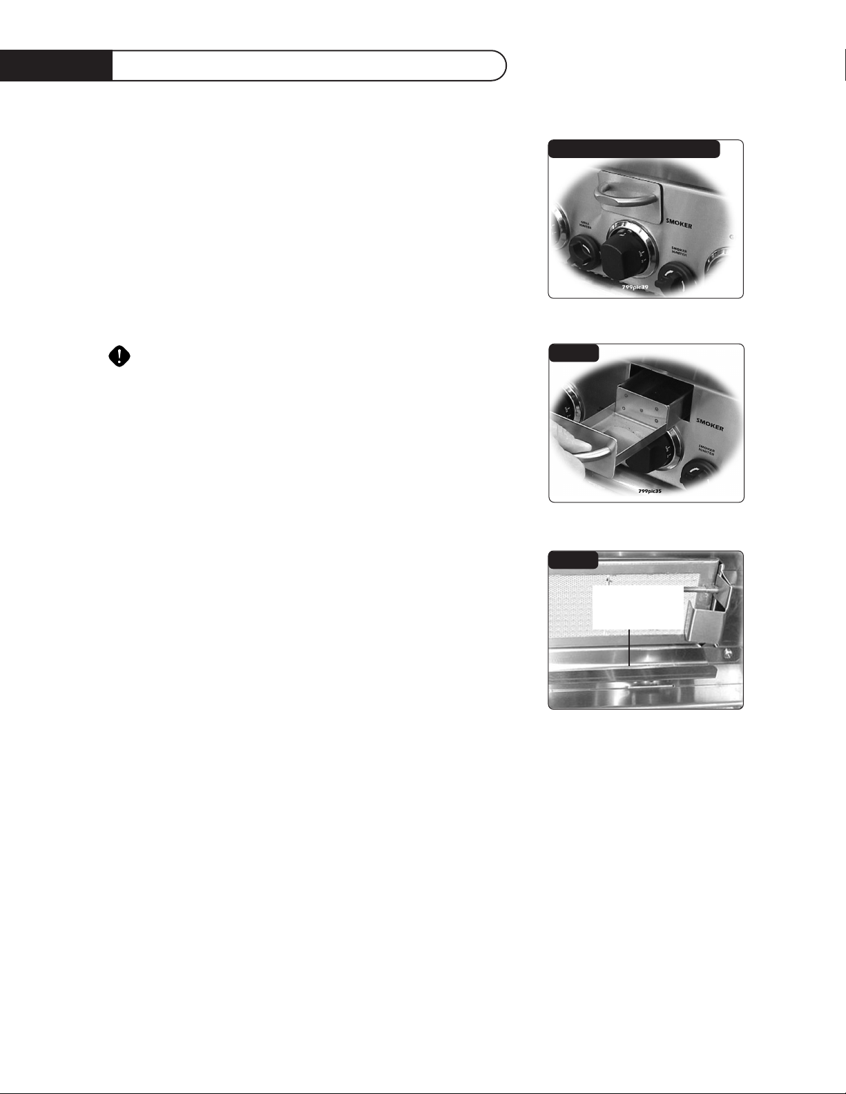
Us i ng The Smoker System
36/ 48 MODELS ONLY:
The smoker system on each grill consists of a stainless steel slide out
tray which is positioned above a 5,000 BTU burner.The burner is
controlled by a precision brass valve which is capable of being turned
down to very low heat levels.The system may be used alone for low
temperature roasting and smoking or in conjunction with any
combination of other burners. When using the smoker system in
conjunction with the optional infrared rotisserie burner you’ll find it
helpful to use the low setting of the smoker burner to minimize the
heat rising up to the rotis basting pan. Staggering the meat away from
the smoker burner also helps.
To minimize burn potential do not remove the smoker tray when hot.
27 MODELS ONLY:
The smoke flavor tray: Located directly beneath the rotis burner is a
stainless steel tray which is designed to hold wood chips or herbs for
adding a smoke flavor to foods. Smoker tray is designed to enhance
flavor only.
TO LIGHT THE SMOKER BURNER 36/48 MODELS
ONLY:
Open the lid and remove the smoker tray. Locate the burner visually
by looking through the cut-out in the valve panel. Push and turn the
control knob to the “Lite” position and immediately turn the smoker
rotary igniter knob (which is to the immediate right of the smoker
knob) until the burner is lit or 4 seconds pass. If the burner doesn’t
ignite wait 5 minutes for any accumulated gas to dissipate then try
again. If the burner will not light after several attempts, wait 5 minutes
then match light using a long stemmed match or lighter through the
cut-out in the valve panel. Once lit, fill the smoker tray and replace.
NOTE: Because of the location of the Smoker Flavor Tray on the 27” BQR Model, the rotis burner acts
as the burner for the Smoke Flavor Tray (see fig. 19).
WOOD CHIPS:
There are many wood chips available for purchase and selection is based on personal taste. The most
common wood chips used are mesquite or hickory. Mesquite has a sweeter taste and is commonly
used with poultry and seafood. Hickory is best suited for red meats. Use of oak, cherry, maple, aspen
or apple is also common while aromatic herbs like sage, bay leaves, thyme or basil may also be used.
Always soak the chips in water prior to putting them into the tray. To start, you may want to
use the “HI” position to start the chips smoking, then reduce the heat to a lower level to prevent them
from drying out and flaming. If the wood chips do flame up, add a small amount of water to extinguish
the flame.This should be done carefully through the top in the grill area, or by pulling the tray out
slightly. Use caution when adding water to a hot tray to avoid steam burns, and never
completely remove a hot tray. The tray may also be filled with water to produce steam.Whether
smoking or steaming the lid should remain closed as much as possible to maximize the effect. During
extended roasting periods it is normal to add fresh wood chips to the tray several times.
FIG. 17 36 / 48 Grill Smoker System
FIG. 19
FIG. 18
27” SMOKER
FLAVOR TRAY
Page 20
19
Us i ng The Rotisserie Burner
BQRS AND BQARS SERIES ONLY:
The grill rotisserie system is designed to cook items from
the back using infrared heat. The location of the burner
allows the placement of the rotis basting pan (included)
beneath the food to collect juices and drippings for
basting and gravy. To flavor the contents of the basting
pan, you can add herbs, onion, garlic, or spices. Hams are
especially good with the addition of pineapple slices and
brown sugar to the basting pan. The rotisserie burner is
an infrared type which provides intense searing radiant
heat. Preferred by chefs over other methods, this
intense heat is magnificent for searing in the natural
juices and nutrients found in quality cuts of meat.
Once lit, the rotis burner will reach cooking temperatures in about 1 minute.The orange/red glow will even
out in about 5 minutes. The rotis motor is equipped
with metal gears and is capable of turning up to a 25 lb.
cut of meat or poultry. On the 27” Grills, (see Fig. 21) the
motor is mounted to a metal channel which attaches to
the left side of the grill and gets tightened into place
with a thumb screw. Ensure that the motor is straight prior to tightening the thumb screw.
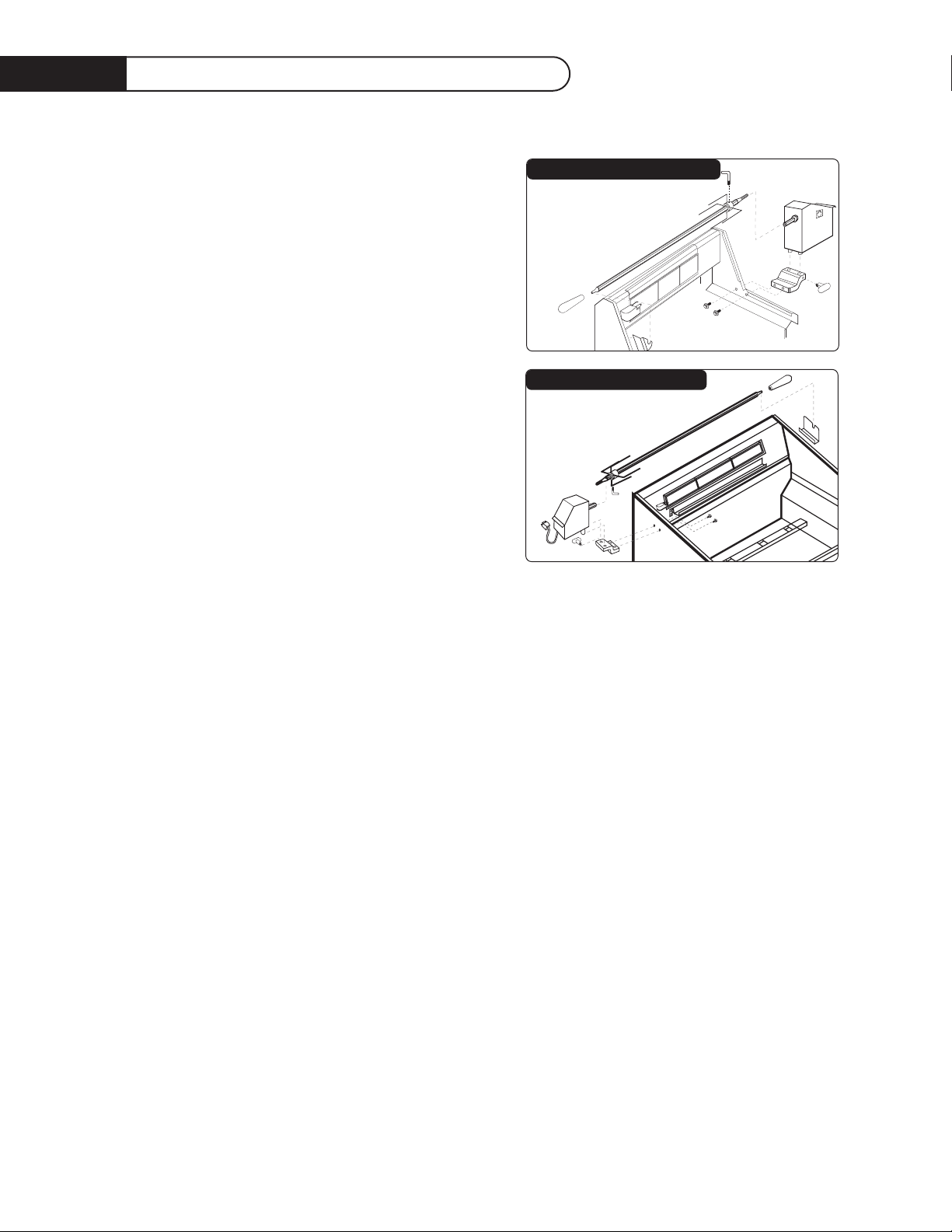
The rotis motor on the 36” / 48” Grills is secured down to a cast rotis block with the black screwdown knob. The rotis block is in turn bolted to the right side panel (see Fig. 20). On 36” and 48”
Grills, the skewer for the rotis is assembled into the motor assembly by placing the pointed end into
the motor, and resting the threaded end on the support at the left side of the grill (right side on 27”
Grills). With the skewer pushed as far as possible into the motor, the grooved skewer bushing should
rest on the left side bracket (right side on 27” models with rotisserie).
To load the skewer begin with the handle in place, and slide one of the meat holders (prongs facing
away from the handle) onto the skewer. Push the skewer through the center of the food, then slide the
second meat holder (prongs toward the food) onto the skewer. Center the product to be cooked on
the skewer then push the meat holders firmly together.Tighten the L shape nut with pliers. It may also
be necessary to wrap the food with butchers string or dental floss (never use nylon or plastic string)
to secure any loose portions. Once the food is secure insert the skewer into the motor. If needed,
remove the grill racks. Place the basting pan beneath the food. It is normal for the skewer to flex when
larger cuts of meat are being cooked (27” Models Only).
TO LIGHT:
All BQR Series Only: The location of the rotis burner makes it more susceptible to strong wind
conditions, more so than the protected grill burners. For this reason you should avoid operating the
rotis during windy conditions. As an added safety feature we’ve equipped the burner with an automatic
safety valve which will not allow gas to flow to the rotis burner unless the following conditions are
present with the knob on:
1.The safety valve button is pressed, and held down.
2.The safety valve thermocouple has been sufficiently heated to keep safety valve open.
FIG. 20 36 / 48 Grill Rotisserie System
FIG. 21 27 Grill Rotisserie System
Page 21

Us i ng The Rotisserie Burner
Open the lid. Push and turn the control knob to the “Lite” position. Press the safety valve button, hold
in, and begin turning the rotary igniter button located next to the rotis knob. It may be necessary to
turn the igniter knob several times until the burner lights. You’ll hear a snapping sound. At the same
time, a spark will be provided at the safety probe. Hold the safety valve button in for about 5 seconds
or until the burner remains lit. This is the only burner on the grill with a safety valve. Once lit, turn
control knob to desired setting. If the burner does not light within 4 seconds, release the safety valve
button and turn the control knob to “off”. If the igniter does not function, the burner can be lit by
holding a lit match to the burner (with the control knob at “Lite” and the safety valve button pressed).
• If relighting a hot burner, wait 5 minutes.
• Never leave the control knob on if rotis is not in use..
• Never light a grill burner under the rotis, while rotisserie burner is lit.
WARNING: Electrical Grounding Instructions:
This appliance (rotisserie motor) is equipped with a three-prong (grounding) plug for your protection
against shock hazard and should be plugged directly into a properly grounded three-prong receptacle.
Do not cut or remove the grounding prong from this plug.
The Rotisserie motor must be electrically grounded in accordance with local codes or, in the absence
of local codes, with the National Electrical Code, ANSI/NFPA 70-1990. Keep the rotis motor electric
cord away from the heated surfaces of the grill. When not in use, remove and store the motor in a
dry location.
20
Page 22

21
Care And Cleaning
GRILL RACKS:
The easiest way to clean the grill is immediately after cooking is completed and after turning off the
flame.Wear a barbeque mitt to protect your hand from the heat and steam. Dip a fine brass bristle
barbeque brush in tap water and scrub the hot grill. Dip the brush frequently in the bowl of water.
Steam, created as water contacts the hot grill, assists the cleaning process by softening any food
particles.The food particles will fall onto the ceramic tubes and burn or fall into the drip tray. If the grill
is allowed to cool before cleaning, cleaning will be more difficult.
DRIP TRAYS:
The full width drip trays will collect grease from the grill section and boil overs and spills from the
power burners.Allow the pan and its contents to cool before attempting to clean. Clean grease from
the pan often to avoid the possibility of a grease fire.
CERAMIC TUBES:
It is not necessary to remove the ceramic tubes for cleaning.They burn themselves clean during the
next cooking operation. Periodically the trays holding the ceramic tubes need to be turned over, and
shaken free of debris for a thorough cleaning. How often you use the grill and the amount and type of
food cooked will determine when it is necessary to clean the ceramic tubes. If grease can be seen on
the top of the tubes or if you get a lot of flare-up during cooking, the tubes need to be turned over
and heated on “HIGH” for 30 minutes; longer for heavy soil.
STAINLESS STEEL:
The Grill is made from non-rusting and non-magnetic stainless steel. After initial usage, areas of the
grill may discolor from the intense heat given off by the burners, this is normal. There are many
different stainless steel cleaners available. Always use the mildest cleaning procedure first, scrubbing in
the direction of the grain.To touch up noticeable scratches in the stainless steel, sand very lightly with
dry 100 grit emery paper in the direction of the grain. Specks of grease can gather on the surfaces of
the stainless steel and bake on to the surface and give the appearance of rust. For removal use an
abrasive pad (Scotch Brite is good) in conjunction with a stainless steel cleaner.Always rub in the
direction of the grain.
Note: Stainless steel tends to rust in presence of chlorides and sulfides specially in coastal areas. To
ensure rust prevention, wash all stainless steel surfaces every 3-4 weeks with fresh water and
stainless cleaner.
Page 23
22
Burner Removal And Cleaning
RANGETOP BURNERS:
The grill power burners (BQRS Models Only) are cast iron and
occasionally it will be necessary to remove surface rust to ensure
proper performance. Frequency of cleaning will depend on the
climate & location, and how often you use the grill. If allowed to
build up the rust may form layers which must be removed promptly.
The walls of the burners are thick so they can withstand many years
of use. BEFORE REMOVING: Ensure the gas supply is off and the
knobs are in the “off” position. Make sure the grill is cool.
GRILL BURNER:
Remove the grill racks, then lift out the grill radiant tray. Grasp the burner, pull it up and slightly to the
rear of the unit so the burner head comes off the brass orifice at the front, angle the burner sideways,
and remove.
POWER BURNER:
Remove the top grate. Lift out aeration pan from around burners. Lift and remove the front and rear
power burners.
BURNER CLEANING:
Clean the exterior of the burner with a wire brush. Clear stubborn scale with a metal scraper. Clear
any clogged ports with a straightened paper clip. Never use a wooden toothpick as it may break off and
clog the port. Shake out any debris through the air shutter. Use a flashlight to inspect the burner inlet
to ensure it is not blocked. If obstructions can be seen, use a metal wire coat hanger that has been
straightened out.
ORIFICE CLEANING:
With the burner removed, remove the orifice and shine a flashlight through the opening to ensure
there is no blockage. Use a needle to clear any debris. Be extremely careful not to enlarge the hole or
break off the needle.
SMOKER BURNER:
The smoker burner can be removed and cleaned by unplugging the igniter wire and lifting out the
burner. Cleaning is similar to the grill burner. Replace the burner by sliding the air shutter over the
brass orifice, centering it in the hole.
IT IS EXTREMELY IMPORTANT TO CENTER THE BURNER ON THE ORIFICE PROPERLY.
Be careful not to upset the air shutters’ original position (unless readjusting). Lower the rear of the
burner into the cutouts on the support channel at the rear of the burner box. Make sure it is level and
does not rock. Light all of the burners and check for proper flame characteristics. If adjustments are
necessary, refer to (page14). Do this prior to cooking on the grill.
REPLACING ROTARY IGNITER: BEFORE REPLACING AN IGNITER, PERFORM
THIS SIMPLE TEST. . .
Remove the drip tray. From underneath the valve panel, look upwards and locate the end of the igniter
wire, where it is connected. Disconnect the wire and place the metal blade of a screwdriver about 1/8"
from the terminal of the rotary igniter.
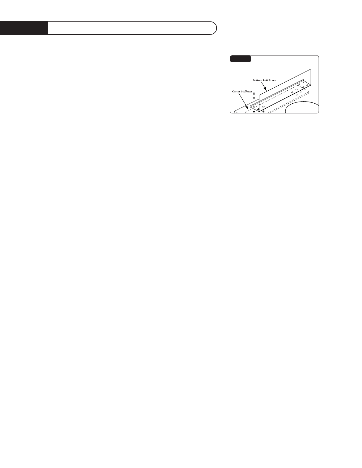
FIG. 22
Page 24

23
Troub les hooting
Turn the igniter knob. If the igniter is good, a spark will jump across to the screwdriver. If no spark,
replace the igniter. If there is a spark, examine the wire of the electrode for cracks and cuts.Also
examine the electrode for grease and debris or see if the electrode tip is bent. Is the tip sparking to
the top of the electrode bracket? The rotary igniter may be replaced from the front by removing the
drip pan and reaching behind the valve panel to unplug the igniter wire.Then hold the rotary igniter
nut and loosen by rotating the igniter. If removing the valve panel is necessary, begin by removing all the
knobs, then remove the (2) screws from the igniter, and the (4) corner torx head screws of the valve
panel.
SPIDER AND INSECT WARNING!!! Spiders and insects can nest in the burners of this or any other
grill, and cause the gas to flow from the front of the burner.This is a very dangerous condition which
can cause a fire to occur behind the valve panel, thereby damaging the grill and making it unsafe to
operate. When to Look For Spiders: You should inspect the burners at least once a year or
immediately if any of the following conditions occur:
1. The smell of gas in conjunction with the burner flames appearing yellow.
2. The grill does not reach temperature.
3. The grill heats unevenly.
4. The burners make popping noises.
BEFORE CALLING FOR SERVICE:
If the grill does not function properly, use the following checklist before contacting your dealer for
service.You may save the cost of a service call. Troubleshooting is for general purposes only. If the
problem persists and you feel you require service, contact your dealer or the nearest authorized
agency to perform service. Only authorized agencies can perform warranty service. Call DCS Customer
Service at (888) 281-5698.
Grill won’t light when the rotary igniter is turned:
1. Remove the grill top grates and the ceramic radiant trays, watch the igniter tip. You should
see a spark jump from the tip of the igniter when the knob is turned.
2. If there is no spark when the rotary igniter knob is turned, check the gas supply to the unit
and purge the line of any air.
3. Attempt to match light the burner, (see page 17) check to see that other burners on the
unit operate. Clean igniter tip of any debris.
Burner flame is yellow or orange, in conjunction with the odor of gas:
1. Check the burner inlet for obstructions. Check the air shutter for proper adjustment.
2. Grill may be in a dusty area. Move to less dusty area if possible.
Low heat with knob in “HI” position:
1. If only one of the burners appears low, clean the orifice and burner, clearing ports of any
obstruction.
2. Grill may be in a dusty area. Move to less dusty area if possible.
3. Check for proper gas supply and pressure.
4. Pre-heat grill for a full 15 minutes.
5. If using L.P. gas check for empty tank.
Optional rotis won’t light:
1. If there is a spark at the thermocouple?
2. Does the rotis burner light when attempting to match light?
Optional rotis lights, but will not hold flame once button is released:
1. Continue holding safety valve button in depressed position until burner remains lit when
released.
Page 25
24
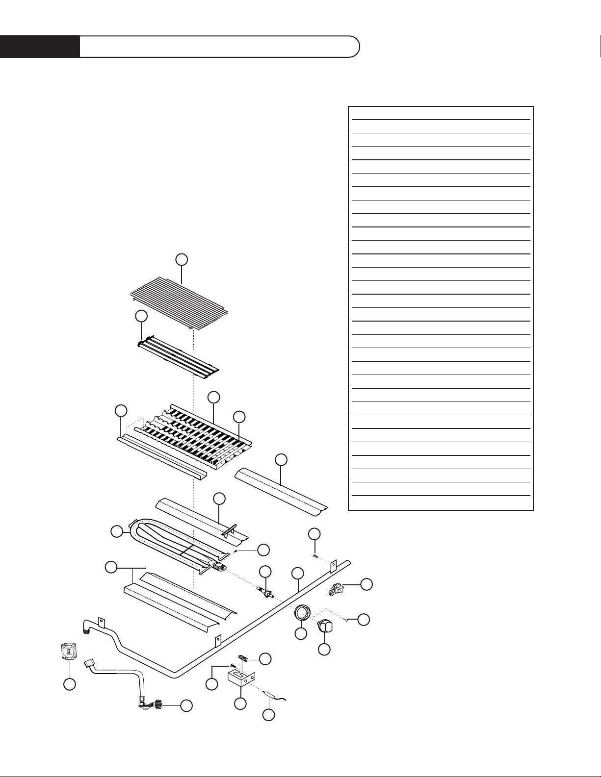
Grill Burner As semb ly
355fig.04.eps
1
2
3
4
5
6A
7B
19
10
9
17
18
11
15
13
20
21
14
16
12
7A
8
6B
ITEM DESCRIPTION PART NO.
1 Grill Rack S/S 27F 19014-02
2 Grate 36/48 S/S 18197-01
Grate 36/48 18197
3 Radiant 32218-02
4 Ceramic Rods 32224
5 Radiant Cap 32264
6a 27”C/ Heat Shield w/Assy. 32220
6b C/Heat Shield w/Assy. 32268
7a SS Grill Burner 32217
7b Air Shutter Screw 12003-2
8 Heat Shield 36/48 32219
Heat Shield 27 32336
9 Manifold 48DBQ 18198
Manifold 48DBQA 18207
Manifold 36DBQA 18203
Manifold 36DBQ 18209
Manifold 27D 18034-01
10 Control Valve 13017
11 Control Knob 14154
12 Knob Bezel 14006-PL
13 Collector Box 32210-01
14 NI-Chrome Wire Coil 32313
15 Electrode 16281
16 Screw 15001-28
17 Rotary Igniter K-Rotary Ign
18 Bezel Screw 15001-29
19 Manifold bolt 15001-06
20 Regulator (L.P. GAS) 13230
21 Regulator (NAT. GAS) 13035
Page 26

25
Grill Body Parts List
ITEM DESCRIPTION PART NO.
1 Roll Top Lid 48DBQ/36DBQA 32293-01
Roll Top Lid 48DBQA 32293-02
Roll Top Lid 36DBQ 32293-03
Roll Top Lid 27DBQR 30602-27
2 Handle End Cap Spacer 18174
3 Handle End Cap 18164-PL
4 Shoulder Bolt 15089-3
5 Handle Tube 48DBQ/36DBQA 32048-02
Handle Tube 48DBQA 32048-01
Handle Tube 36DBQ 32048-03
Handle Tube 27 32048-05
6Warming Rack 48DBQ/36DBQA 32248-01
Warming Rack 48DBQA 32248-02
Warming Rack 36DBQ 32248-03
Warming Rack 27DBQ 32314
7 Firebox w/assy. 48DBQ/36DBQA 32247-01
Firebox w/assy. 48DBQA 32247-02
Firebox w/assy. 36DBQ 32247-03
8 Body Assembly 27D 32271
9 Bolt (small) 15002-26
10 Warming Rack Ret. 27 L/H 32340-01
Warming Rack Ret. 27 R/H 32340-02
11 Landing Ledge w/assy. 27 32043
12 Cage Nut 15029-02
13 Logo Spring Clip 15073
14 Valve Panel 48DBQR 32212-01-PA
Valve Panel 48DBQAR 32212-02-PA
Valve Panel 48DBQ 32212-07-PA
Valve Panel 48DBQA 32212-08-PA
Valve Panel 36DBQR 32212-03-PA
Valve Panel 36DBQ 32212-04-PA
Valve Panel 36DBQAR 32212-05-PA
Valve Panel 36DBQA 32212-06-PA
Valve Panel 27DBQ 32272-03-PA
Valve Panel 27DBQR 32272-01-PA
15 DCS Logo 17129-01
16 Torx Screw 15002-41
17 Drip Pan 48D 30645-2
Drip Pan 36D 30645-1
Drip Pan 27 32260
18 Drip Pan Handle 48D 32050-01
Drip Pan Handle 36D 32050-02
Drip Pan Handle 27D 32041
19 Screw 15002-17
Keps Nut 15021-04
Hex Nut 15004-09
20 Trim w/assembly 48D 32235-03
Trim w/assembly 36D 32235-04
Page 27
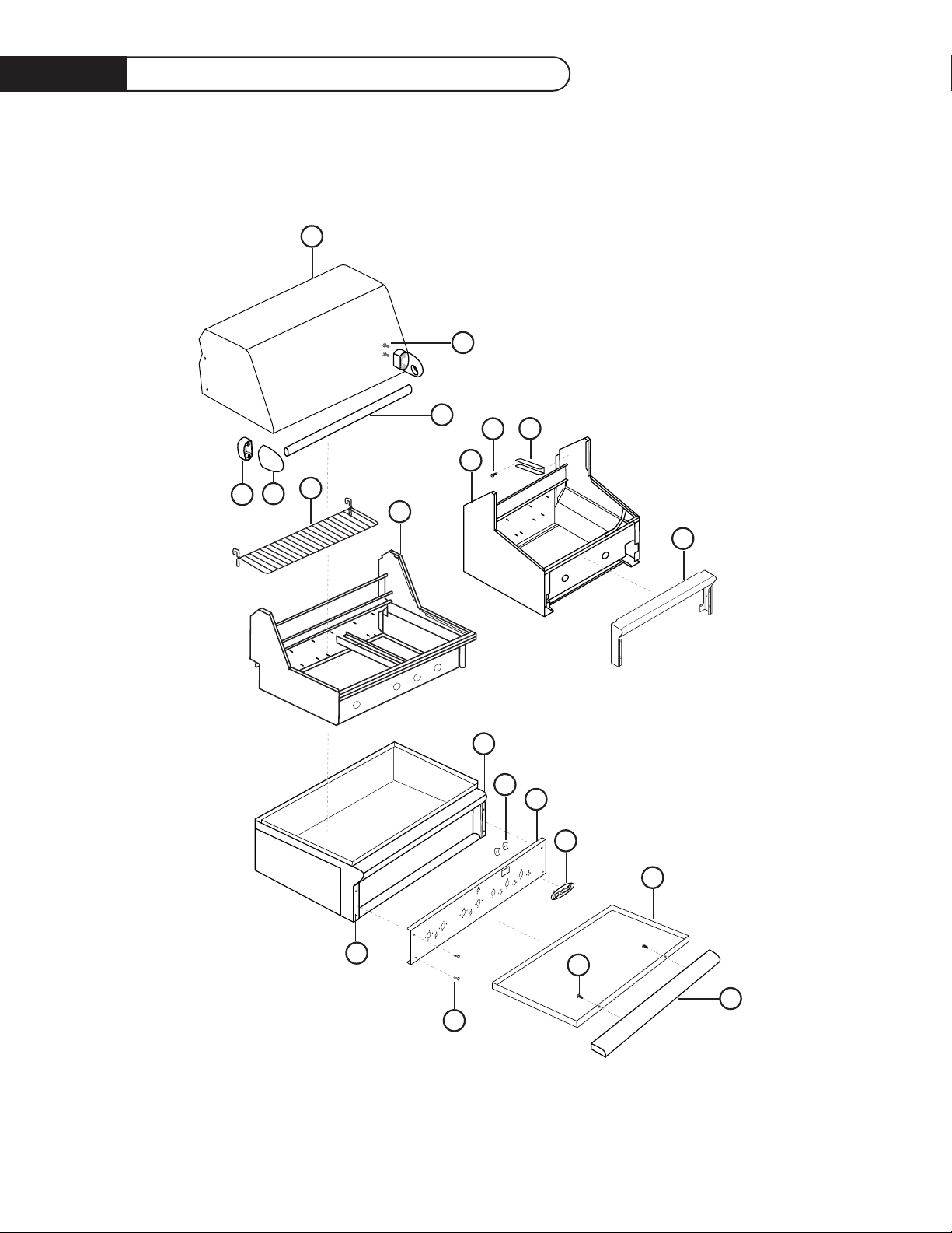
26
Grill Body Parts List
355fig.05.eps
8
1
4
5
2
3
6
7
8
9
10
11
18
17
19
16
15
14
13
20
12
Page 28
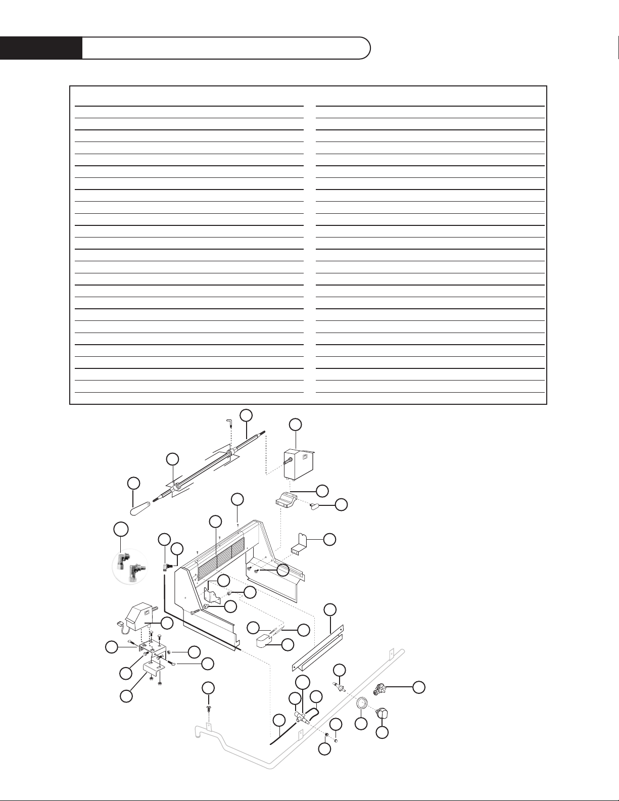
27
Rotiss erie As sembly
ITEM DESCRIPTION PART NO.
1 Rotisserie Handle 18040
2 Meat Holder Assembly 19010-02
3 Rotisserie Rod 48dbqar 19054-05
Rotisserie Rod 48dbqr 19054-02
Rotisserie Rod 36dbqar 19054-04
Rotisserie Rod 36dbqr 19054-01
Rotisserie Rod 27dbqr 19054-03
4 Rotisserie Motor Assembly 32069
5 Rotisserie Mount Base 14155
6 Rotisserie Mount Knob 14161
7 Rotis Receiving Bracket 27D 32285
8 Screw 15001-23
9 Rotis Burner 48dbqar/36dbqr 12021-1
Rotis Burner 48dbqr/36dbqar 12021-2
Rotisserie Burner 27dbqr 12021-2
10 Orifice Elbow 18193
10a Orifice Elbow 27 18020-1
11 Rotis Receiving Bracket 48/36 32233
12 Acorn Nut 15019-06
13 Plug Orifice NG 13025-50
Plug Orifice LP 13025-58
Plug Orifice LP 27D 13025-57
Plug Orifice NG 27D 13025-50
14 Roller Assembly 14197-01
15 Screws 15001-23
16 Rotisserie Motor 27D 32069-02
17 Rotisserie Motor Bracket 27F 32346
18 Nut 15021-09
19 Bolts 15150
20 Thermocouple 13007-2
21 Electrode Rotisserie 13055-5
Electrode Rotisserie 27D 16282
22 Electrode Cover L/H 32047-01
Electrode Cover R/H 32047-02
23 Flavor Tray 27F 32294
24 Manifold Bolt 15001-06
25 Tube Cut/Form 48BQAR 32133-01
Tube Cut/Form 48BQR/36BQR 32133-02
Tube Form 27 30841-04
26 Safety Valve 18110
26a Ferrule 18077-2
27 Tubing Formed 6.75 30841-02
Tubing Formed 8 30841-03
28 Safety Valve Bezel 14160
29 Safety Valve Knob 14108
30 Control Knob 14154
31 Rotary Igniter K-Rotary Ign
32 Knob Bezel 14006-PL
33 Control Valve 13017
34 Thumb Screw 15117-01
35 Rotis Motor Backer Plate 32345
1
2
3
10a
10
13
9
8
4
5
6
7
15
11
12
14
16
18
17
19
22
21
20
24
25
27
28
29
26
26a
31
30
32
33
23
34
35
Page 29
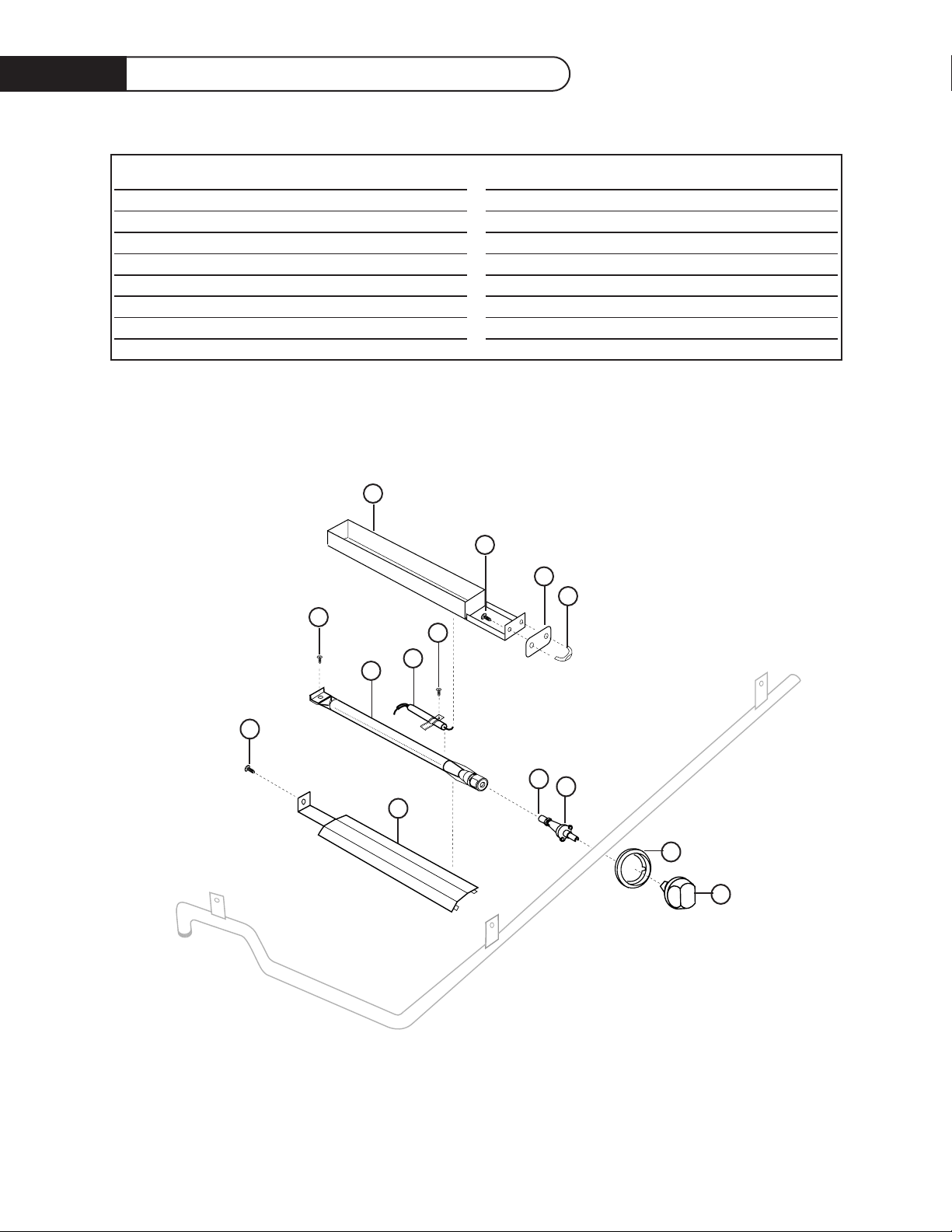
28
Smoker Burner Ass embly
ITEM DESCRIPTION PART NO.
1Smoker Tray w/assembly 32231
2 Screw 15139
3Smoker Plate 32228
4Smoker Pull Handle 18204-01
5 Screw 15139
6 Electrode Smoker 13012-6
7Smoker Burner 30639-1
8 Screw 15139
9 Screw 15139
10 Smoker /Burner Support 32226
11 Control Valve 13017-01
12 Orifice L.P. 13005-71
Orifice Natural 13005-59
13 Bezel 14006-PL
14 Control Knob 14154
14
13
11
12
10
9
8
1
2
3
4
7
6
5
355fig.07.eps
Page 30
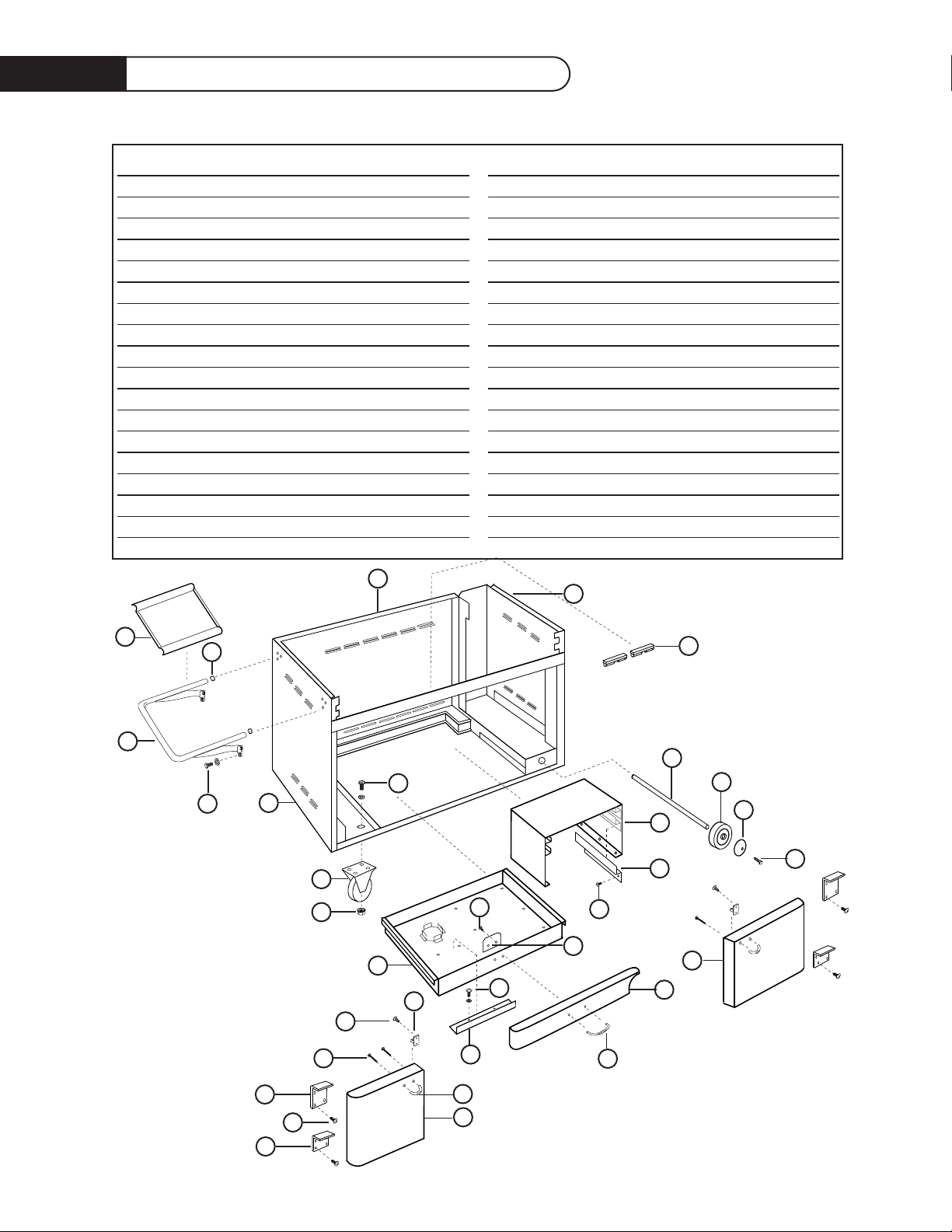
29
48 Grill Cart Parts list
355fig.08.eps
22
ITEM DESCRIPTION PART NO.
1 Side Shelf Tray 41067
2 Side Shelf End Cap 14205
3 Side Shelf Assembly 18212
4 Bolt 15003-06
5 Left Body Panel 41053
6 Rear Body Panel 41055
7 Hex Bolt 15150
8 Right Side Body Panel 41054
9Door Catch 14204
10 5” Caster 18022
11 Nut 15021-09
12 Drawer 41056
13 Screw 15001-23
14 Door Stop Tab 41094
15 Drawer Shelf 41068
16 Spare Shelf Holder L/H 41069-02
Spare Shelf Holder R/H 41069-01
17 Screw 15002-17
18 Axle 41062
19 8” Solid Rubber Wheel 18264
20 Hub Cap 41075-01-SP
21 Torx Screw 15002-45
22 Right Door Assembly 41098-02
23 Kickplate Weld Assembly 41097
24 Pull Handle 18024-02
25 Screw 15002-17
26 LP Drawer Dam 41077
27 Pull Handle 18024-01
28 Left Door Assembly 41098-01
29 Screw 15002-41
30 Screw 15139
31 Screw 15002-26
32 Top Hinge R/H 41092-01
Top Hinge L/H 41092-02
33 Bottom Hinge R/H 41093-02
Bottom Hinge L/H 41093-01
32
31
30
29
12
11
10
5
3
1
2
4
7
28
27
25
13
26
24
23
21
15
16
14
17
20
19
18
22
9
33
6
8
9
Page 31
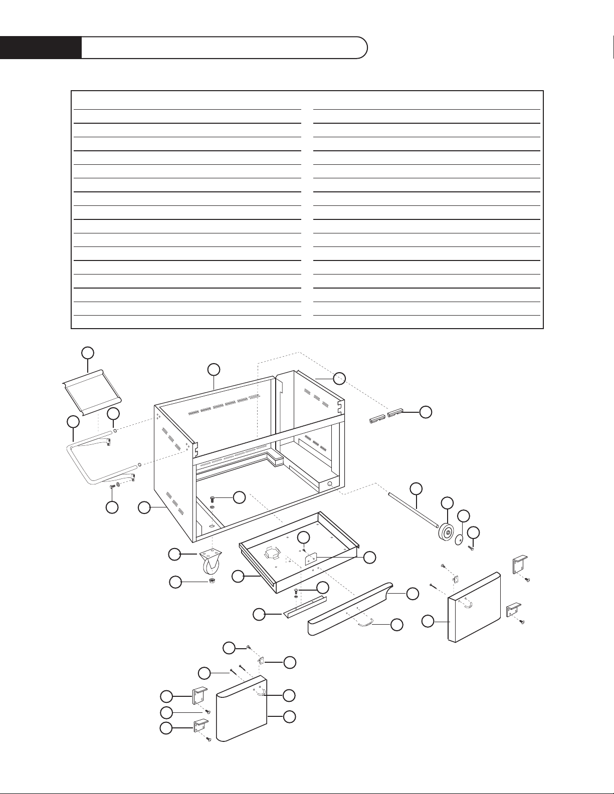
30
36 Grill Cart Parts List
ITEM DESCRIPTION PART NO.
1 Side Shelf Tray 41067
2Side Shelf End Cap 14205
3 Side Shelf Assembly 18212
4 Bolt 15003-06
5 Left Body Panel 41053
6 Rear Body Panel 41083
7 Hex Bolt 15150
8 Right Side Body Panel 41054
9Door Catch 14204
10 5” Caster 18022
11 Nut 15021-09
12 Axle 41062
13 8” Solid Rubber Wheel 18264
14 Hub Cap 41075-01-SP
15 Torx Screw 15002-45
16 Kickplate Weld Assembly 41097-01
17 Pull Handle 18204-02
18 Right Door Assembly 41113-01
19 Screw 15001-13
20 Door Stop Tab 41094
21 Hex Bolt 15002-17
22 LP Drawer Dam 41077
23 Screw 15002-41
24 Pull Handle 18024-01
25 Left Door Assembly 41113-02
26 Screw 15139
27 Top Hinge R/H 41092-01
Top Hinge L/H 41092-02
28 Screw 15002-26
29 Bottom Hinge R/H 41093-02
Bottom Hinge L/H 41093-01
30 Cart Drawer 41084
27
26
9
17
18
16
15
14
13
12
19
21
20
22
30
10
5
3
1
6
2
4
7
8
9
11
24
25
28
29
23
Page 32
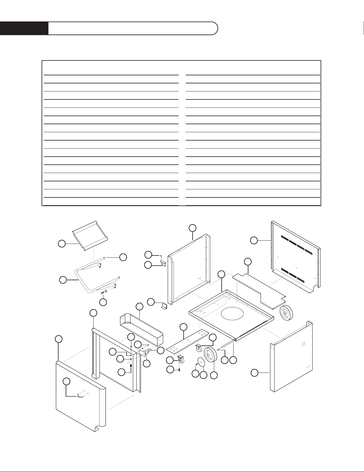
31
27F Grill Cart Parts List
ITEM DESCRIPTION PART NO.
1Front Door Panel 41139
2 Pull Handle 18204-01
3 Door Liner 41140
4 Spring 15198-01
5Keps Nut 15021-04
6Washer Nylon 15199
7 Screw 15001-26
8 Screw 15139-01
9 Hex Nut 15021-04
10 Catch Bracket 41142
11 Door Pocket 41146
12 Caster Stiffener 41148
13 Caster W/Brake 18027
14 Hex Bolt 15150
15 Caster W/Out Brake 18027-1
16 Torx Screw 15002-41
17 Hub Cap 41075-SP
18 Wheel 18098
19 Axle Spacer 41151
20 Axle 41150
21 Side Panel R/H 41145-02
22 Bottom Panel 41149
23 Tank Retainer 41153
24 Back Panel 41141
25 Hinge Bracket Btm. 41143-02
26 Hinge Bracket Top 41143-01
27 Pin Weld Assembly 15028
28 Side Panel L/H 41145-01
29 Side Shelf Tray 41067
30 Side Shelf Handle 18212
31 Side Shelf End Cap 14205
32 Bolt 15003-06
1
2
3
11
28
12
4
5
6
7
8
10
13
15
14
16
17
18
20
19
9
21
22
23
24
25
26
27
29
31
30
32
Page 33

32
Service
HOW TO OBTAIN SERVICE:
BEFORE YOU CALL FOR SERVICE:
See page 21, follow troubleshooting guide first, then call for service if not resolved.
For warranty service, contact your local DCS authorized service agency. Provide him with the Model
Number, Serial Number, and date of installation, and a brief description of the problem. If you need
assistance in locating the authorized service agency in your area please contact our DCS Customer
Service Department for an authorized service agent near you, our number is (888) 281-5698.
Your satisfaction is of the utmost importance to us. If a problem cannot be resolved to your
satisfaction, please write at:
Write:
DCS
Attention: Consumer Relations
5800 Skylab Road Huntington Beach, CA 92647
Page 34

33
Warranty
LENGTH OF WARRANTY:
One (1) Year Full parts and Labor Covers the entire product
Five (5) Year comprehensive warranty covering the porcelainized cast iron rangetop burners,
grill radiant assemblies, and drip pans. Should structural deterioration occur to the degree of
non-performance, a replacement will be furnished.
Lifetime Warranty on all stainless steel components, including stainless steel grill burners
and stainless steel grill racks (excluding discoloration or surface corrosion).
DCS WILL PAY FOR
All repair labor and parts found to be defective due to materials or workmanship for one full year “IN
HOME” warranty during the first year of ownership. This does not apply if the unit was subjected to
other than normal household use. Service must be provided by Authorized Factory Agent during
normal working hours. No charges will be made for repair or replacement at the location of initial
installation or factory for parts returned pre-paid, through the dealer and claimed within the warranty
period, and found by DCS to be defective.
Replacement will be F.O.B. DCS, and DCS will not be liable for any transportation costs, labor costs, or
export duties. This warranty shall not apply, nor can we assume responsibility for damage that might
result from failure to follow manufactures instructions or local codes, where the appliance has been
tampered with or altered in anyway or which, in our judgement, has been subjected to misuse,
negligence, or accident. Implied warranty shall not extend beyond the duration of this written
warranty.This warranty is in lieu of all warranties expressed or implied and all other obligations or
liability in connection with the sale of this appliance.
DCS WILL NOT PAY FOR
• Installation or start-up.
• Shipping damage.
• Service by an unauthorized agency.
• Damage or repairs due to service by an unauthorized agency or the use of unauthorized parts.
• Service during other than normal working hours.
• Improper installation, such as improper hook-up, etc.
• Service visits to teach you how to use the appliance; correct the installation; reset circuit breakers
or replace home fuses.
• Repairs due to other than normal household use.
•Damage caused from accident, abuse, alteration, misuse, incorrect installation or installation not in
accordance with local codes.
• Units installed in non-residential application such as day care centers, bed and breakfast centers,
churches, nursing homes, restaurants, hotels, schools, etc.
This warranty applies to appliances used in residential applications; it does not cover their use in
commercial situations. This warranty is for products purchased and retained in the 50 states of the
U.S.A., the District of Columbia and Canada.This warranty applies even if you should move during the
warranty period. Should the appliance be sold by the original purchaser during the warranty period, the
new owner continues to be protected until the expiration date of the original purchaser’s warranty
period. This warranty gives you specific legal rights.You may also have other rights which vary from
state to state.
Page 35

34
Notes
Page 36

Notes
35
Page 37

Notes
36
Page 38

Part No. 17355 Rev. B
Litho in USA 12/2004
As product improvement
is an ongoing process at
DCS, we reserve the right
to change specifications
or design without notice.
5800 Skylab Road, Huntington Beach, CA 92647 Tel: (714) 372-7000
Fax: (714) 372-7001 Customer Service (888) 281-5698
www.dcsappliances.com
 Loading...