

Page 1

CART ASSEMBLY
30” CSS GRILL CART
INSTALLATION INSTRUCTIONS
IMPORTANT!
SAVE THESE INSTRUCTIONS
●
Before you begin, read these instructions completely and carefully. Do not jump ahead or skip any step.
●
Some parts have sharp edges; care must be taken when handling the various components to avoid injury.
●
Please, read safety information provided in these instructions before beginning assembly. Wear gloves when handling.
●
Two or more people should work together to assemble the cart and grill head.
●
NOTE: Avoid using side shelf to move cart. Push or pull cart by grasping corners of grill head.
GETTING STARTED
●
Remove and discard packaging.
Contents Included:
Your cart is packaged in one box. The box contains your 30” grill
cart and a universal hardware kit to be used for BGB30-BQR grill
installation and may contain extra hardware for your convenience.
CONTENTS QTY.
Machined
Philip screws
10-24X1/2”
Screw
1/4-20X1/2”
5
5
CONTENTS QTY.
1
30” Grill Cart
1
Instruction
Screw
1/4-20X2”
Keps Nut
1/4-20
Rubber
Bumper
TOOLS REQUIRED
1
5
5
Eye Goggles
Work Gloves
Power
Screwdriver
or Variable
Speed Drill with
Phillips -tip #2
Attachment
10mm Wrench
or Socket
3/32” Allen
Wrench
1
Page 2
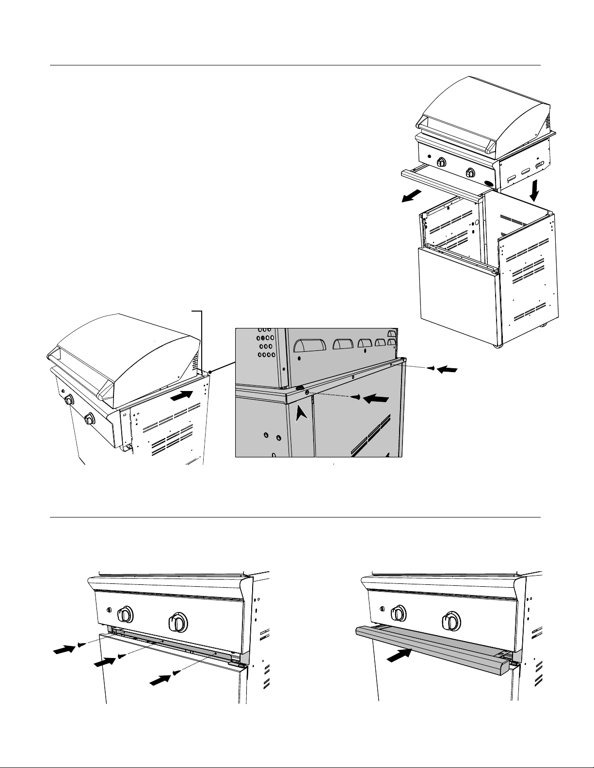
STEP 1
Grill Placement onto Cart (2 persons required)
1 Remove drip tray/pan for easier handling.
Place grill head on cart.
2 Slide back.
3 Ease over rear flange.
4 Secure with screws.
After drip tray/pan is removed,
carefully place grill head on cart
(2 person minimum).
Pinch point
Once Grill rests on cart, slide grill
to rear of cart as shown.
Grill head should rest over rear
cart flange as shown above.
Lift grill over rear flange of cart
(be aware of pinch points).
STEP 2
Front End Screw Installation
1 Install remaining (3) screws (10-24 x 1/2”) in front of head to cart.
2 Slide drip tray/pan back into place. Move side shelf bars up and set trays into place.
Secure grill to rear of cart with
(2) Phillips-head screws
provided (10-24 x 1/2”).
Secure grill to the front of the cart
with Phillips-head screws (provided).
Slide drip tray/pan back into place. Move
side shelf bars up and set trays into place.
2
Page 3

STEP 3
Bolt Installation
After head is in place, install the bolt (1/4-20 x 2”)
in the location shown.
NOTE: This bolt secures side bracket to grill head
assembly for added side shelf strength.
Apply Loctite 242 (blue) to the first 3-4 threads
prior to installation of this bolt.
Ensure the bolt goes
through into the Grill
Head to secure
STEP 4
Side Shelf adjustment
●
With extended use, the shelf may become
unleveled and needs to be readjusted.
●
In between the bracket where the shelf hinge
is, is an adjustment grub screw.
●
Grasping the shelf, carefully raise up the shelf
and hold while with other hand using a 3/32
allen wrench turn the screw to the desired
level.
Side Shelf
Bolt
(1/4-20 x 2”)
Underside of
Side Shelf
Grub Screw
(Use Allen Wrench/Key to adjust)
STEP 5
Gas Hookup - LP
Attach LP gas line connector hose assembly (as shown in “LP Gas Hookup” section - Use/Care Guide) and then
connect to LP tank as shown.
1 Check that the cylinder valve is
OFF by turning clockwise.
2 Using the correct spanner, tighten
the connecting nut as tight as
possible. Do not use a spanner on a
handwheel connection.
3 After fitting the regulator it may
have assumed a position out of the
horizontal, this is not important,
DO NOT TWIST THE REGULATOR.
4 When gas is required, turn the cylinder valve anti-clockwise.
Leak test all connections before operating the appliance.
3
Page 4

STEP 6
LP Tank Restraint
IMPORTANT!
If you intend to store a 20 lb Type 1 LP Cylinder inside the cart, then the tank restraint rings on the bottom of the cart
must be used.
1 Remove the two front screws on the tank retainer rings inside the cart as shown.
2 Loosen the two rear screws (but don’t remove them)
3 Open the tank rings enough to insert the LP tank.
4 Pull the rings back around the LP tank
5 Secure all four screws.
Loosen rear two screws
Remove front two screws
Open up the tank rings
Close up the tank rings and
tighten all four screws
4
Page 5

ASSEMBLAGE DU CHARIOT
30 “CSS GRIL PANIER
INSTRUCTIONS D’INSTALLATION
IMPORTANT!
CONSERVER CES INSTRUCTIONS
●
Lisez toutes les instructions avant de commencer. Évitez de sauter des étapes.
●
Certaines pièces ont des bords coupants; faites attention lorsque vous manipulez les différents composants pour éviter
de vous blesser.
●
Veuillez lire les consignes de sécurité de ce manuel avant de commencer l’assemblage. Portez des gants.
●
Il faut deux personnes ou plus pour assembler le chariot et la tête du gril.
●
REMARQUE : Évitez de déplacer le chariot par la tablette latérale.
Poussez ou tirez le chariot en saisissant les coins de la tête du gril.
POUR COMMENCER
●
Retirez l’emballage.
CONTENU QTE.
Contenu :
Le chariot est emballé dans une seule boîte. Celle-ci contient le chariot
de gril 30 po et un kit de matériel universel destiné à l’installation du
gril BGB30-BQR qui comprend du matériel supplémentaire pour votre
commodité.
CONTENU QTE.
1
Chariot de gril 30”
1
Vis phillips
usinées
10-24X1/2”
Vis
1/4-20X1/2”
Vis
1/4-20X2”
Écrou à rondelle
dentée 1/4-20
Butée de
caoutchouc
OUTILS REQUIS
5
5
1
5
5
Lunettes de sécurité
Instructions
Gants de travail
Tournevis
mécanique
ou perceuse à
vitesse variable
avec embout
Phillips no. 2
Clé ou douille
10mm
Clé Allen 3/32”
5
Page 6

ÉTAPE 1
Placement du gril sur le chariot (il faut 2 personnes pour cette tâche)
1 Retirez le récipient à graisse/ramasse- gouttes pour faciliter le travail.
Placez la tête du gril sur le chariot.
2 Glissez-la vers l’arrière.
3 Placez-la doucement sur la bride arrière.
4 Fixez à l’aide de vis.
Une fois le récipient à graisse/
ramasse-gouttes enlevé, placez
la tête du gril sur le chariot avec
précaution (il faut au moins 2
personnes pour cette
Point de
pincement
Une fois le gril sur le chariot, glissez-le
vers l’arrière du chariot tel qu’indiqué.
La tête du gril doit reposer pardessus la bride arrière du chariot
tel qu’indiqué ci-dessus.
Fixez le gril à la partie arrière du
chariot à l’aide de (2) vis Phillips
fournies.
Placez le gril par-dessus la bride
arrière du chariot (faites attention aux
points de pincement).
ÉTAPE 2
Pose de la vis de la partie avant
1 Posez les (3) vis (10-24X1/2 po) restantes à l’avant de la tête du chariot.
2 Glissez le récipient à graisse/ramasse-gouttes. Déplacez les barres de la tablette latérale vers le haut et mettez les plateaux
en place.
Fixez le gril à la partie avant du chariot
à l’aide de vis phillips (fournies).
Glissez le récipient à graisse/ramasse-gouttes.
Déplacez les barres de la tablette latérale vers
6
le haut et mettez les plateaux en place.
Page 7

ÉTAPE 3
Pose du boulon
Une fois la tête mise en place, posez le boulon
(1/4-20 x 2 po) omis à l’étape 1, et serrez tous les
boulons du support. Serrez jusqu’à ce que tous les
côtés affleurent la garniture seulement.
Remarque :
Ce boulon fixe le support latéral sur la tête du gril
afin de renforcer la tablette latérale. Appliquez du
Loctite 242 (bleu) aux 3 ou 4 premiers pas avant
de poser ce boulon.
Vérifiez que le boulon
traverse dans la tête Grill
pour sécuriser
ÉTAPE 4
Réglage de la tablette latérale
●
Avec l’usage, les étagères risquent de n’être
plus de niveau et doivent donc être réajustées.
●
Entre le support où la charnière du plateau est,
est une vis de réglage de grub.
●
Une vis de réglage de 3/8 po se trouve dans
le support, là où la poignée coulisse. Saisissez
la poignée tel qu’indiqué, soulevez la tablette
et retenez-la tout en visant de l’autre main à
l’aide d’une clé Allen 3/32 au niveau voulu.
Side Shelf
Boulon
(1/4-20 x 2”)
Dessous de la
tablette latérale
Grub vis
(Utilisez la clé Allen / Key pour
régler)
ÉTAPE 5
Branchement du gaz propane
Fixez le tuyau et le connecteur de la ligne de gaz propane (tel qu’indiqué à la section « Branchement du gaz
propane, puis branchez à la bouteille de propane comme indiqué ci-dessous.
1 Vérifier que le robinet de la
bouteille est OFF en tournant dans
le sens horaire.
2 En utilisant la bonne clé, serrer
l’écrou de raccordement aussi serré
que possible. Ne pas utiliser une clé
sur une connexion de la manivelle.
3 Après le montage d’un régulateur,
il peut avoir pris une position
sur l’horizontale, cela n’a aucune
importance, NE PAS TOURNER LE
REGULATEUR.
4 Lorsque le gaz est nécessaire, tournez le robinet de la bouteille anti-
horaire. Test de fuite toutes les connexions avant de faire fonctionner
l’appareil.
7
Page 8

ÉTAPE 6
Restreint de réservoir LP
IMPORTANT!
Si vous avez l’intention de stocker un cylindre LP de 20 lb type 1 à l’intérieur du chariot, les anneaux de retenue du
réservoir sur le bas du chariot doit être utilisé.
1 Retirez les deux vis avant sur les anneaux de retenue du réservoir à l’intérieur du chariot comme indiqué.
2 Desserrez les deux vis arrière (mais ne les retirez pas)
3 Ouvrez suffisamment les bagues du réservoir pour y insérer le réservoir.
4 Retirer les anneaux autour du réservoir de propane
5 Fixez les quatre vis.
Desserrez les deux vis
arrière
Enlever les deux vis avant
Ouvrez les bagues du réservoir
Fermez les anneaux du réservoir
et serrez les quatre vis
8
Page 9

Page 10

Page 11

Page 12

As product improvement is an ongoing process, we
reserve the right to change specifications or design
without notice.
Fisher & Paykel Appliances Inc.
695 Town Center Drive, Suite 180 Costa Mesa.
CA 92626-1902 USA
www.dcsappliances.com
590272 C 02.17
 Loading...