

Page 1

THE PROFESSIONAL SIDE BURNER
Installation, Use and Care Guide
MODELS:
BGB131
BGB132
BGB131-BI
BGB132-BI
Page 2

Page 3

A MESSAGE TO OUR CUSTOMERS
We are glad that you selected the professional side burner by DCS. Because this appliance contains features not
ound on any other burner, we recommend that you read this entire booklet before your first use. Keep it in a
f
handy place as it has answers to questions that may occur during future use.
eel free to contact us if we can help you. When you write please include the model and serial number of the
F
Burner. We thank you for buying the professional side burner and wish you many years of enjoyment.
To help serve you better, please fill out and submit your Product Registration by visiting our website at
www.dcsappliances.com and selecting “Customer Care” on the home page and then select “Product Registration”.
For your convenience, product questions can be answered by a DCS Customer Care Representative by phone:
1-888-936-7872, or email: customer.care@fisherpaykel.com.
NOTE: Please write the Model, Code and Serial Numbers on this page for references (located on the inside of the
left side of the appliance)
MODEL NUMBER CODE SERIAL NUMBER
NOTE: Inspect the product to verify that there is no shipping damage. If any damage is detected, call the shipper
and initiate a damage claim. DCS by Fisher & Paykel is not responsible for shipping damage.
DO NOT discard any packing material (box, pallet, straps) until the unit has been inspected.
WARNING!
Improper installation, adjustment, alteration, service or maintenance can cause property damage, injury or death.
Read the installation, operating and maintenance instructions thoroughly before installing, using or servicing this
equipment.
WARNING!
If the information in this manual is not followed exactly
personal injur
y other appliance. An LP cylinder not connected for use shall not be stored in the vicinity of this or any other
an
appliance.
y or death. Do not store or use gasoline or other flammable vapors and liquids in the vicinity of this or
, a fire or explosion may result causing property damage,
WARNING!
Do not try lighting this appliance without reading the “Lighting Instructions” section of this manual. This outdoor
cooking gas appliance is not intended to be installed in or on recreational vehicles , boats or in a non-ventilated
room. For outdoor use only.
FOR YOUR SAFETY
If You Smell Gas:
1. Shut off gas to the appliance.
2. Extinguish any open flames.
3. Open lid.
4. If odor continues, immediately call your gas supplier or your fire department
Installation and service must be performed by a qualified installer, service agency or the gas supplier.
PLEASE RETAIN THIS MANUAL FOR FUTURE REFERENCE.
1
Page 4

TABLE OF CONTENTS
SAFETY PRACTICES AND PRECAUTIONS 3-4
INSTALLATION
Installation of Side Burner on 30” Grill 4-7
nstallation of Side Burner Built-in Model 8-9
I
Gas Hook-up 10-11
Leak Testing 12
Burner Adjustment 12
Installer Checklist 13
USING THE SIDE BURNER
Lighting Instructions 14
CARE AND MAINTENANCE 15
TROUBLESHOOTING 16
PARTS LIST
Single Side Burner - BGB131 & BGB131-BI 17
Double Side Burner - BGB132 & BGB132-BI 18
WIRING DIAGRAM
Single and Double Side Burner 19
SERVICE 20
WARRANTY 21-22
2
Page 5

SAFETY PRACTICES & PRECAUTIONS
Improper use or installation is dangerous. Carefully follow these instructions.
■
Always remove the cover before lighting the professional side burner. Never use the side burner if a leak is
present.
■
Do not use a flame to check for gas leaks.
■
Do not let children use the side burner.
■
Do not leave children unattended near the side burner.
■
Never let children crawl or hang on the side burner.
■
Exercise care when operating the side burner. The burner grate can get hot enough to cause burns during
operation.
■
Never leave the side burner on unattended.
■
Always wait 5 minutes before relighting the burner to allow any accumulated gas to dissipate. Should the burner
go out during use, turn off the gas valve and wait 5 minutes before attempting to relight. Always follow the
lighting instructions. Never lean over a lit burner.
■
Never cook without the drip pan in place, pushed all the way to the rear of the burner box.
■
Use only in well ventilated areas.
■
Do not use in garages, breezeways, sheds, or other such enclosed areas.
■
Keep the area surrounding the side burner clear and free from combustible materials, gasoline, other flammable
liquids or vapors, charcoal lighter fluid, and trash.
■
Do not obstruct the flow of combustion and ventilation air to the side burner. On cart mounted units, keep area
beneath the burner free of debris. If the burner is built-in, do not store gas cylinders beneath the unit without
adequate ventilation.
WARNING!
Do not store items of interest to children above or at the back of any appliance. Children could be seriously injured
if they should climb onto the appliance to reach these items.
■
Keep the side burner covered when not in use.
■
Never connect an unregulated gas line to the side burner.
f the side bur
■
I
be checked for gas leaks and obstructions in the burner.
■
Thoroughly clean the side burner on a regular basis.
■
Only use the side bur
vice versa, a factory conversion kit (see page 10 for conversion kit information) is required.
NOTE:
duct must be installed by a licensed plumber or gas fitter when installed within the Commonwealth of
o
This pr
Massachusetts.
ner has not been used for an extended period of time (over winter, for example) the unit should
e. To change from LP gas to natural, or
ner with the type of gas specified on the ra
ting pla
t
3
Page 6

SAFETY PRACTICES & PRECAUTIONS
REAR
FRONT
IGNITION
BURNER
IGNITION
10 - 5/8 "
13
"
13
"
13
"
13
"
10 - 5/8 "
12-
3/4 "
15
-3/4"
10 -1/8"
23-
3/4"
10 -1/8"
26-
3/4"
Single Side Burner
Double Side Burner
2
"
2
"
SPIDER AND INSECT WARNING!
Spiders and insects can nest in the burner(s) or orifices of this or any other gas appliance, and can block or restrict
the burner. This can cause a flash back to the control panel. This is a very dangerous condition which can cause a
fire to occur, thereby damaging the unit and making it unsafe to operate.
You must inspect the burner(s) at least once a year or immediately if any of the following conditions occur:
1. The smell of gas in conjunction with the burner flames appearing yellow.
2. The side burner(s) does not reach temperature.
3. The side burner(s) heats unevenly.
4. The burner(s) make popping noises.
■
Do not attempt to disconnect any gas connections while your burner is in use, or the gas supply is on.
■
When the side burner is stored indoors the gas supply must be disconnected and, if using an LP gas cylinder, the
cylinder must be stored outdoors in a well-ventilated area.
■
Keep any electrical supply cord away from the heated surfaces of the professional side burner.
■
On cart mounted units, never move without first allowing the side burner and/or grill to cool and ensuring that
the gas supply is turned off. Fold the side shelf down, and push; never pull the grill.
■
Never use the side burner in a windy area.
INSTALLATION
INSTALLATION OF SIDE BURNER ONTO 30” CART (BGB 131/132 MODELS ONLY)
SIDE BURNER DIMENSIONS
FRONT
REAR
SIDE
4
FRONT
REAR
SIDE
Page 7
INSTALLATION
INSTALLATION OF SIDE BURNER ON 30” CART
Important
!
Read all instructions before you begin. Do not jump ahead or skip any step. Side shelf must be removed prior
to installation.
CAUTION!
Some parts have sharp edges; care must be taken when handling the various components to avoid injury. Please,
read safety information provided in these instructions before beginning assembly. Wear gloves when handling.
GETTING STARTED
■
Remove packaging.
■
Remove side burner from inside and discard packing.
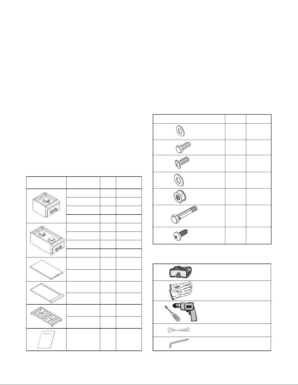
CONTENTS INCLUDED:
Your side burner is packaged in one box. The box
contains your side burner and a universal hardware kit
to be used for installation and may contain extra
hardware for your convenience.
Con
tents
Description Q
BGB131-BIL 1 70175
BGB131-BIN 1 70176
ty.
Par
t No.
Contents Qty. Part No.
Washer Flat
1/4x.938
Screw
1/4-20X1/2”
2
5 211323
4 211278
Screw #10
4 211371
Washer #10
4 211394
Nut #10
211375
BGB131L 1 70177
BGB131N 1 70515
BGB132-BIL 1 70178
BGB132-BIN 1 70179
BGB132L 1 70180
BGB132N 1 70604
Cover (131) 1 218614
Cover (132)
ip Pan
Dr
(131)
Drip Pan
(132)
te (131)
a
Gr
Grate (132) 1 220496
tion
nstruc
I
1
1 224826
1 237358
1 210645
1 238044
218613
Tools Required:
Shoulder Bolt
1/4-20x5/16
Screw
10-24x1/2
Pan Head
hillips -tip #2 A
P
10 mm
1
211442
2 211242
Eye Goggles
Work Gloves
Power Screwdriver or
Variable Speed Drill with
3/32” Allen Wrench
ench or S
r
W
ttachmen
ocket
t
5
Page 8
INSTALLATION
INSTALLATION OF SIDE BURNER ON 30” CART
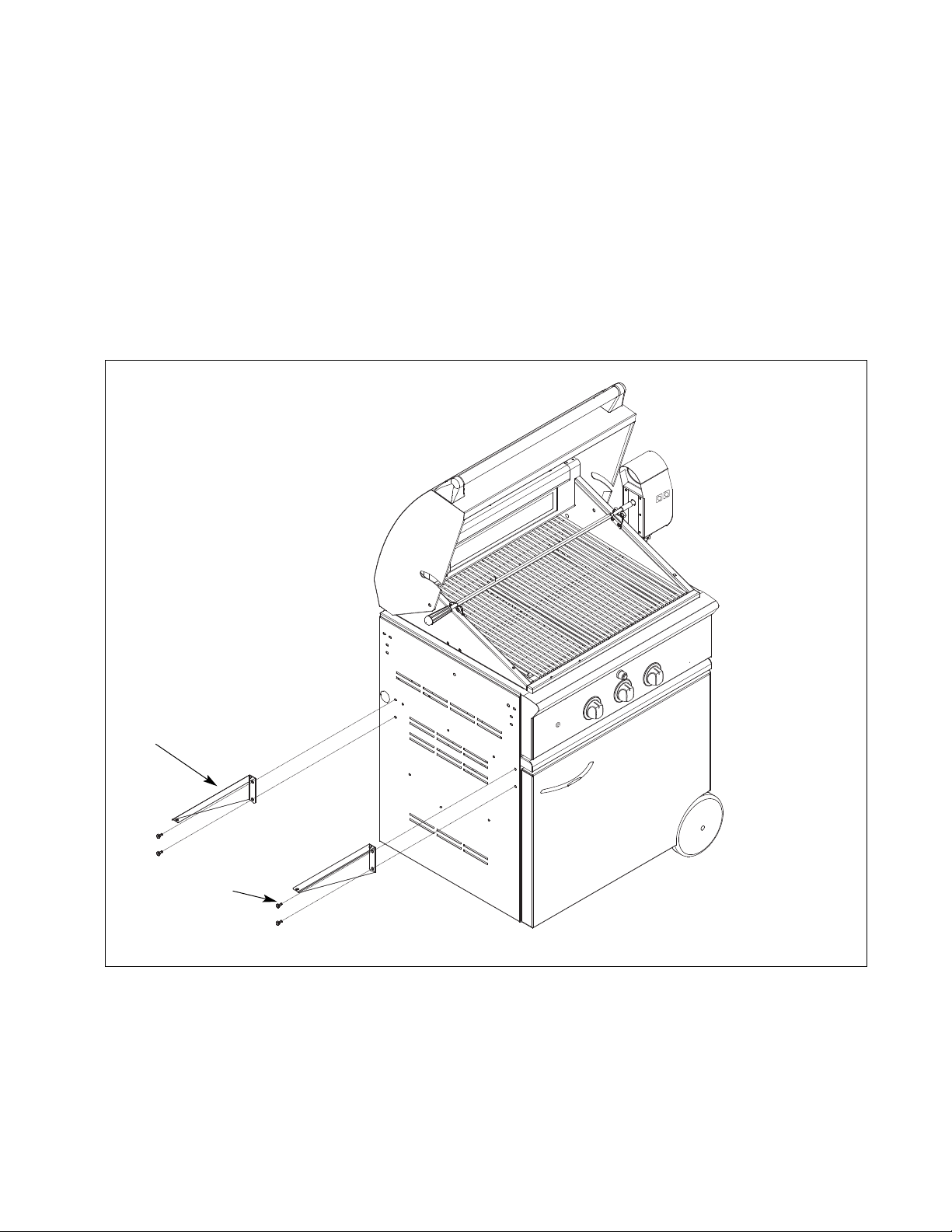
STEP 1
Remove the cover, grate, and drip pan from the side burner.
STEP 2
olt the support brackets to the grill cart side panel with (4) 1/4 x 20 bolts provided.
B
Note:
For the BGB131 side burner only, use (2) #10 sheet metal screws (211242) to bolt the back support bracket.
SUPPORT BRACKET
6
BOLT
FIG. 01
Page 9

INSTALLATION
INSTALLATION OF SIDE BURNER ON 30” CART
STEP 3
1. Bolt the side burner to the grill cart side panel from the under side of the burner assembly with a shoulder bolt
in the front and 1/4 x 20 bolt in the back as shown. Do not forget to use 1/4 flat washers. Do not tighten.
Adjust the side burner until it is level to the grill; then tighten securely.
2. Bolt the support brackets to the bottom of the side burner with (4) #10-24 machine screws, nuts and washers
provided.
3. Replace the drip pan, grate and cover.
Note:
Once the side burner is assembled, refer to the “Gas Requirements” section for proper gas hook-up requirements.
WASHER FLAT
1/4 X .938 (2PCS)
BOLT (1/4 – 20)
W #10 (4 PCS)
SCRE
ASHER #10 (4 PCS)
W
NUT#10 (4 PCS)
SIDE BURNER
Shoulder Bolt
1/4-20 x 5/16
FIG. 02
7
Page 10
INSTALLATION
COUNTER TOP
NON-COMBUSTIBLE
COMBUSTIBLE OR
6"
min.
6"
min.
6"
min.
BACK VIEW
COUNTER TOP
COUNTER TOP
NON-COMBUSTIBLE
COMBUSTIBLE OR
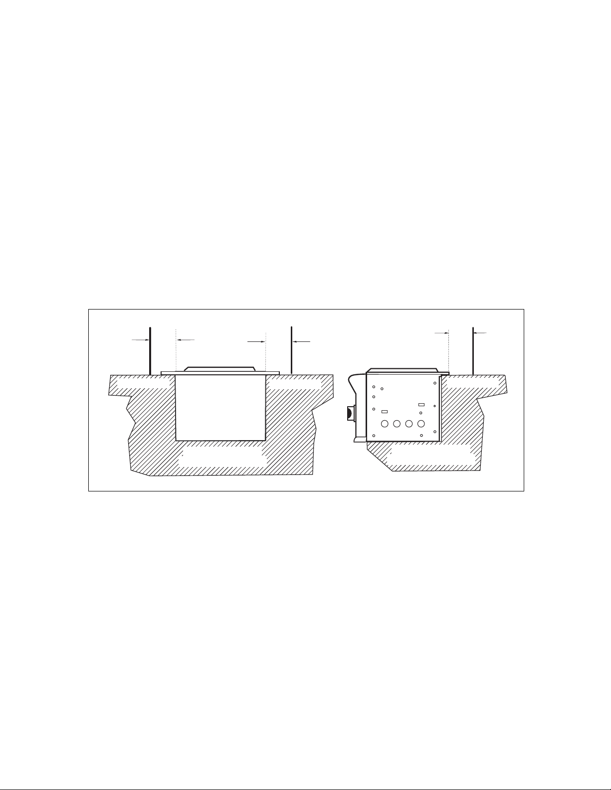
INSTALLATION OF SIDE BURNER, BUILT-IN MODEL
All BGB131-BI and BGB132-BI models can be installed into a combustible enclosure with zero clearance from
he back, side and bottom below the counter top level as shown in Fig. 03.
t
A minimum of 6” from the back and sides must be maintained from the professional side burner above the
ooking surface (see Fig. 03).
c
When determining a suitable location, take into account concerns such as exposure to wind, proximity to
traffic paths, and keeping any gas supply lines as short as possible. Locate the side burner only in a wellventilated area. Never locate the side burner in a garage, breezeway, shed, or other such enclosed areas.
It is recommended that ventilation holes are provided in the enclosure in the event of a gas leak. The counter
and supporting ledges or deck must be level and flat.
Important!
Gas fittings, regulator, and installer-supplied shut-off valves must be easily accessible.
8
FIG.03
Page 11

INSTALLATION
12"
10-
1/8"
2" X 2" opening
for gas supply line
A
MODEL A
BGB131-BI 12"
BGB132-BI 22-3/4"
note: the deck is
not required
REAR
F
RONT
I
GNITION
BURNER
IGNITION
10 - 5/8 "
10 - 5/8 "
12
"
12
"
"
14-9/16
"
14-9/16
1
11-
3/8"
2
"
16
-1/16"
10-1/8"
22-
1/8"
2
"
10-1/8"
26-
5/8"
Single Side Burner
Double Side Burner
3
-1/8"
3
-1/8"
1/2"
1/2"
2
INSTALLATION OF SIDE BURNER, BUILT-IN MODEL
SIDE BURNER DIMENSIONS
FRONT
REAR
FRONT
REAR
STANDARD CONSTRUCTION CUTOUT REQUIREMENTS
SIDE
SIDE
9
Page 12

INSTALLATION
GAS HOOK-UP
GAS REQUIREMENTS:
Verify the type of gas supply to be used, either natural or LP. Make sure the marked gas on the appliance
rating plate(s) and hook-up kit agrees with that of the supply.
IMPORTANT!
Never connect an unregulated gas line to the appliance.
An installer supplied gas shut-off valve must be installed in an easily accessible location. All installer
supplied parts must conform to local codes, or in the absence of local codes, ANSI/NFPS-770-1984.
All pipe sealants must be an approved type and resistant to the actions of LP gases. Never use pipe sealant
on flare fittings.
All gas connections should be made by a qualified technician and in accordance with local codes and
ordinances. In the absence of local codes, the installation must comply with the National Fuel Gas Code ANSI
Z223.1.
Gas conversion kits are available from the factory. When ordering, have the model number, and the type of
gas (natural or LP) which you need.
Total gas consumption of the professional side burner with burner(s) on “HIGH” – Table 1 below.
TABLE 1
MODEL Btu/hr
BGB131
17,000
BGB132 34,000
BGB131-BI 17,000
BGB132-BI 34,000
The appliance and its individual shut-off valve must be disconnected from the gas supply piping system
during any pressure testing of that system at test pressures in excess of 1/2 PSIG (3.5kPa.).
The appliance must be isolated from the gas supply piping system by closing its individual manual shut-off
valve during any pressure testing of the gas supply piping system at test pressures equal to or less than 1/2
PSIG (3.5 kPa.).
The installation of this appliance must conform with local codes or in the absence of local codes, with the
National Fuel Gas Code, ANSI Z223.1. Installation in Canada must be in accordance with the Standard
CAN1-b149 and/or .2 (installation code for gas burning appliances and equipment) and local codes.
NATURAL GAS HOOK-UP:
CONNECTION: 1/2” NPT male with 3/8” flare adapter.
OPERATING PRESSURE: 4.0” W.C.
SUPPLY PRESSURE: 5” to 14” W.C. If in excess of 14”W.C., a step down regulator is required.
ompan
Check with your local gas utilit
Be sure to check on type and size of run, and how deep to bury the line. If the gas line is too small, the
professional side burner will not function properly.
10
y c
y or with local c
odes for instructions on installing gas supply lines.
Page 13

INSTALLATION
O
pen Top
M
anifold
Bottomof
1
31 &132 Burner
1/2" Coupling
1
/2" NPT x 2.0”
Nipple
1
/2" NPT to 3/8"
FlareAdapter
R
egulator
T
o Gas Supply
1
/2" NPT x 2.0”
Nipple
GAS HOOK-UP
NATURAL GAS HOOK-UP (continued)
To hook-up the fittings supplied with the side burner, assemble as shown in Fig.04. Use joint compound on
male threads only.
o not use joint compound on the flare end of the 1/2” NPT
D
to 3/8” flare adapter. Ensure that the regulator arrow points
in the direction of gas flow-towards the unit, away from the
supply.
Do not forget to place the installer-supplied gas valve in an
accessible location.
LP GAS HOOK-UP
CONNECTION: 1/2” NPT male with 3/8” flare adapter
(included). Use 90º elbow 1/2” NPT with 3/8” flare
(P/N 212394) for side mount models only when installing on
the cart. Use sealer on 1/2” NPT threads only.
OPER
ATING PRESSURE: 10.0” W.C. side burner uses the LP
regulator from adjoining grill.
SUPPLY PRESSURE: 11” to 14” W.C.
FIG. 04 Natural Gas
Apply joint compound to the threaded end of the side burner gas
inlet and tighten the adapter to the pipe. Assemble the 24” and 30” hoses to the 3/8” flare tee, as shown in
Fig.05. Tighten the regulator hose to the remaining fitting of the 3/8” flare tee.
LP TANK REQUIREMENTS
■
A dented or rusty LP gas cylinder may be hazardous and
should be checked by your LP supplier. Never use a cylinder
with a damaged valve.
■
The LP gas cylinder must be constructed and marked in
accordance with the specifications for LP gas cylinders of the
U.S. Department of Transportation (DOT) and designed for
use with a Type 1 system only.
■
Do not change the regulator/hose assembly from that
empt to use a Type 1 equipped
ed out
or
tt
doors in a w
ell ventila
ed area
t
FIG. 05 LP G
as
supplied with the unit or a
regulator/hose assembly with a standard 510 POL tank/valve
assembly. The cylinder must be provided with a shut-off
alve terminating in an LP gas supply cylinder valve outlet
v
specified, as applicable, for connection Type 1.
■
If the appliance is stored indoors, the cylinder must be
disconnect
ylinders must be st
■
C
ed and removed from the appliance.
out of the reach of children.
■
Gas cylinder supply must be turned off when not in use.
11
Page 14
INSTALLATION
LEAK TESTING
WARNING!
Do not smoke while leak testing. Extinguish all open flames.
Make a soap solution of one part liquid detergent, and one part
water. Never test for leaks with an open flame. For LP units, check
with a full cylinder. Make sure all control valves are in the “OFF”
position. Turn the gas supply “ON”. Check all connections from the
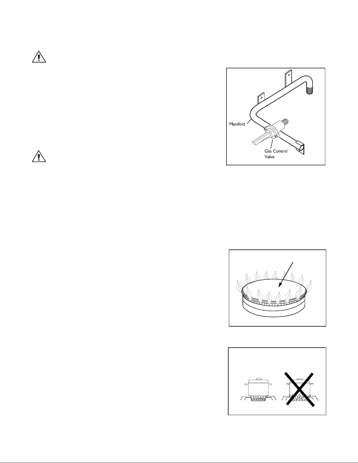
supply line (Fig. 04), or LP cylinder(Fig. 05) up to the manifold pipe
assembly (Fig. 06). Apply the soap solution around the connection
with a spray bottle, brush, or rag. Soap bubbles will appear where
leak is present. If a leak is present, turn off gas supply, tighten any
leaking fittings, turn gas on, and recheck.
WARNING: IMPORTANT!
Inspect the gas supply piping or hose prior to turning the gas “ON”. If
there is evidence of cuts, wear or abrasion, it must be replaced prior to
use. Do not use the side burner if the odor of gas is present. Turn the
control knob to “OFF”, then turn off the gas supply. If using LP, is there gas in the tank? Always keep your face
and body as far away from the burner as possible when lighting.
FIG. 06
BURNER ADJUSTMENT
BURNERS
Your new side burner is equipped with burners typical of those used in
restaurants (Fig. 07). These burners are designed for maximum
cleanability and controlability. The burner should never be operated if
the cap is not in place.
BURNER EFFICIENCY AND FLAME CHARACTERISTICS
It is necessary to keep the burner ports and the igniters clean for
proper lighting and efficient performance of the burners. The burner
flame should burn completely around the burner with no excessive
noise or lif
yellow tips. During initial use, foreign particles in the gas line, or dust
in the air around the appliance may cause an orange flame. This will
disappear with use
FLAME HEIGHT
he c
T
bottom of the cooking utensil, the material of the cooking utensil, the
amount and type of food and the amount of liquid in the utensil. The
ollo
f
■
For safety reasons the flame must never extend beyond the
bott
the side of the pan (see F
ting. The flame should be blue in color and stable with no
.
ect height of the flame mainly depends on the size of the
r
or
wing ar
om of the c
e some basic rules f
ooking utensil. Never allow flames to curl up
or selecting flame height.
.08).
ig
Cap
FIG. 07
PROPER FLAME HEIGHT
■
Utensils which conduct heat slowly (such as glass-ceramic)
should be used with medium t
large amount of liquid
12
, a sligh
tly lar
w flames
o lo
ger flame can be used
. If you are cooking with a
.
FIG. 08
Page 15

INSTALLATION
INSTALLER CHECKLIST
■
Specified clearances maintained to combustibles.
■
Side burner is properly mounted.
■
All internal packaging removed.
■
Burner is seated properly and does not rock.
■
Each burner lights satisfactorily, individually or with adjacent burner lit.
■
Knob(s) turn freely. Bezel(s) centered.
■
Flame adjusted.
■
Pressure regulator connected and set for 4.0"W.C. Natural, 11.2"W.C. LP gas.
■
Manual shut-off valve installed and accessible.
■
Unit tested and free of leaks.
■
User informed of gas supply shut-off valve location.
■
Battery installed in module properly and generates ignition spark when activated.
PLEASE LEAVE THESE INSTRUCTIONS WITH THE USER.
USER, PLEASE RETAIN THESE INSTRUCTIONS FOR FUTURE REFERENCE.
13
Page 16
USING THE SIDE BURNER
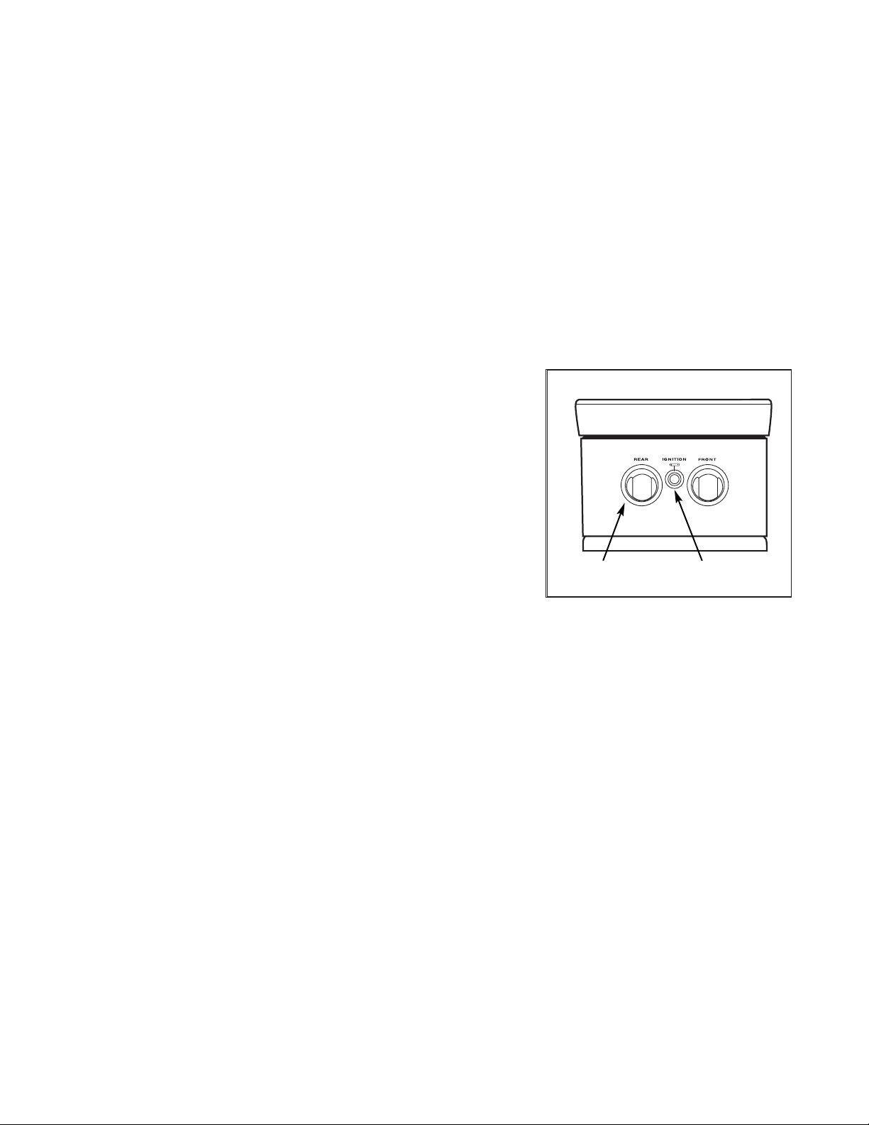
LIGHTING INSTRUCTIONS
First remove the burner cover and any cooking utensils from the burner grate. Push and hold the ignition
utton, turn the control knob to the “HI” position until the burner is lit or 4 seconds pass. If the burner doesn’t
b
ignite, wait 5 minutes for any accumulated gas to dissipate then try again. If the burner will not light after
several attempts, check the troubleshooting instructions on page 16.
MATCH LIGHTING
Hold a lit fireplace match near the burner ports, turn the control knob counterclockwise to “HI”. Rotate the knob
immediately once the burner is lit to the desired setting.
Note:
If you are using propane gas, a slight pop or flash may occur at the burner ports a few seconds after the burner has been
turned “off”. This “extinction pop” is normal for propane gas.
Control
Knob
FIG. 09 BGB132 Shown
Ignition
Button
14
Page 17

CARE AND MAINTENANCE
The side burner will give you years of trouble free service if properly maintained. The body panels and front
alve panel and burner hanger are made from non-rusting high grade stainless steel. The burner is heavy duty
v
cast iron and brass. The venturi tube is brass.
STAINLESS STEEL
There are many different stainless steel cleaners available. Always use the mildest cleaning procedure first,
scrubbing in the direction of the grain. Do not use steel wool as it will scratch the surface. To touch up
noticeable scratches in the stainless steel, sand very lightly with Bear-Tex (p/n 25032).
SIDE BURNER GRATE
The side burner grate is porcelain enamel over cast iron for durability. To avoid burns, do not clean a hot grate.
They may be wiped while in place with hot, soapy water, rinsed and wiped dry thoroughly. Never immerse a hot
grate in water. Due to rapid temperature changes the porcelain may pop off the edges of the grates. If the
grates develop chips, do not be concerned as the base metal, cast iron, soon darkens to blend with the porcelain
enamel. Use care when wiping areas where the enamel has popped off, the edges may be sharp. If cleaning
necessitates grate removal, care should be taken in lifting them. They are very heavy. Be sure to place them on
a protected surface.
DRIP TRAY
A stainless steel aeration pan and drip tray with a
stainless steel handle is located under the burner.
It collects any boil-overs or spills. Pull forward to
remove. Spills should be washed off as soon as
possible to prevent baked on soil.
BURNERS
For proper lighting and performance, keep the
burners clean. It is necessary to clean the burners if
they do not light even though the igniter clicks, if
there has been a severe boil over, or when the flame
does not burn blue. Be certain all burner knobs are
in the off position before attempting to clean the
burners. The burners have been designed for ease of
cleaning. When the grate and burners are cool,
remove the grate. The burner cap and the brass port
ring can easily be lifted off. Wash these parts in hot
soapy water, rinse and dry thoroughly. The burner
caps are porcelain enamel, follow the directions on
the previous page that were given for the burner
grates. A bristle brush can be used to clean out the
toothed burner ports, if necessary. After cleaning, it
is important to make sure the location pins on the
bott
om side of the port ring are properly aligned
with the corresponding holes in the base. Incorrect
alignment will produce a potentially dangerous flame
and poor bur
ner performance (see Fig. 10).
Brass Ring Locating
Pins
Locating Notch
Electrode
oca
L
ting Holes
FIG. 10
Electrode (keep clean)
Cap
Main
Burner
Port Ring
Burner
Base
enturi
V
ELECTRODES
er dampened cotton swab. Be careful not to damage
t
ipe with a w
W
the electrode (see Fig. 11)
a
FIG. 11
15
Page 18

TROUBLESHOOTING
PROBLEM WHAT TO DO
Burner won’t light when the
ignition is pushed.
Burner flame is yellow or
orange, in conjunction with the
odor of gas.
Remove the burner grate. With the control knob in the
“OFF” position, listen to the electrode while engaging
he ignition. There should be a spark from the
t
electrode. When the spark jumps, it makes a ticking
sound.
If there is no spark........
Could be a dead battery. Try replacing the battery.
Or the air gap between an electrode tip and a contact
metal is too far (gap should be 1/8”) or dirty.
If there is a spark... is there gas supplied to the unit and
is the line purged of air? See Fig. 04 and Fig. 05.
Does the other burner of a dual burner model
operate?
Check the orifice or venturi for blockage.
Check the burner for obstructions or dirt. See page 15.
Check for proper gas supply or wrong gas type.
Is the side burner in a dusty area? Move to less dusty
area if possible.
Low heat with knob in “HI”
position.
Is the fuel hose bent or kinked? See Fig. 04 and
Fig. 05.
Is there adequate gas supply available? If it is only one
burner of the dual burner unit that appears low, does
the burner need cleaning? See Fig. 10 and
Fig. 11.
If using LP gas, check for empty tank or low fill level.
16
Page 19

PARTS LIST
SINGLE SIDE BURNER - BGB131 & BGB131-BI
1
5
6
28
27
3
2
15
24
21
17
14
25
26
16
4
23
22
20
19
18
13
11
7
8
9
29
30
31
10
12
NOTE: Part list typical for BGB131 & BGB131-BI models. Illustration shows BGB131-BI model.
DESCRIPTION
ITEM
1 BURNER COVER 214430
PULL HANDLE 212278
2
3 RUBBER BUMPER 212359
TE BK 210645
A
OP GR
T
4
5 D BURNER CAP 210608
6 PORT RING ASSEMBLY 210644
VENTURI
7
8 BASE D BURNER 210639
9 PLATE SUPPORT BURNER 224833
PLATE SUPPORT BURNER (BGB131-BI) 224930
10 BURNER HANGER 224834
11 JET HOLDER LP 210543
JET HOLDER NA
T
12 DRIP PAN ST. STL (BGA131-BI MODEL) 214165
DRIP PAN ST. STL (BGB131 MODEL) 224825
AN HANDLE DBI (BGA131-BI MODEL)
DRIP P
13
DRIP PAN HANDLE 131/132 (BGB131 MODEL) 214428
14 1.5VDC BATTERY AA 221154
PART NO.
210643
210536
214366
ITEM DESCRIPTION PART NO.
15 BEZEL 210935
16 CONTROL KNOB 211188
17 IGNITION MODULE 211872
WIRE BLACK W/ TERMINALS 8” 211823
18
19 WIRE BLACK W/ TERMINALS 10” 211826
20
TUBING 5/16” (9”
LENGTH) 212399
21 ELBOW 1/8NPT X 5/16 T.O.D. 212396
22 FERRULE 5/16 212313
NUT M22 JET HOLDER
23
24 NUT 1/2-24UNF 212312
25 MANIFOLD (BGB131-BI MODEL) 212297
MANIFOLD (BGB131 MODEL) 221924
26 MANUAL GAS VALVE 220575
27 VALVE PANEL (BGA131-BI MODEL) 224854
VE PANEL (BGB131 MODEL) 224839
AL
V
28 VALVE PANEL SCREWS (BGB131-B1) 211300
29 ELECTRODE 210562
SPRING ELEC
30
TRODE
31 CLIP ELECTRODE 210578
210468
210577
17
Page 20

PARTS LIST
DOUBLE SIDE BURNER - BGB132 & BGB132-BI
4
5
6
2
16
29
1
3
25
24
26
20
23
27
28
15
17
14
22
21
19
18
13
7
8
9
10
11
30
31
32
12
NOTE: Part list typical for BGB132 & BGB132-BI models. Illustration shows BGB132-BI model.
ITEM DESCRIPTION PART NO.
1 BURNER COVER 214425
2 PULL HANDLE 212278
3 RUBBER BUMPER 212359
4 TOP GRATE BK 220496
5 D BURNER CAP 210608
6 PORT RING ASSEMBLY 210644
7 VENTURI 210643
BASE D BURNER 210639
8
9 PLATE SUPPORT BURNER 214424
URNER (BGB132-BI) 224931
TE SUPPOR
PLA
URNER HANGER (BGB132 MODEL)
B
10
T B
224817
11 JET HOLDER LP 210543
JET HOLDER NAT
210536
12 DRIP PAN ST. STL (BGA132-BI MODEL) 214164
DRIP PAN ST. STL (BGB132 MODEL) 214427
13 DRIP PAN HANDLE (BGA132-BI MODEL) 214366
DRIP PAN HANDLE 131/132 (BGB132 MODEL) 214428
14 1.5VDC BATTERY AA 221154
15 BEZEL
210935
ITEM DESCRIPTION PART NO.
ONTROL KNOB 211188
C
16
17 IGNITION MODULE 211872
TERMINALS 10” 211826
CK W/
WIRE BLA
18
19 WIRE BLACK W/ TERMINALS 18” 221058
20 TUBING 5/16” (21” LENGTH) 221956
21 ELBOW 1/8NPT X 5/16 T.O.D. 212396
22 TUBING 5/16” (9” LENGTH) 212399
23 NUT M22 JET HOLDER 210468
24 FERRULE 5/16 212313
NUT 1/2-24UNF 212312
25
ANIFOLD (BGB132-BI MODEL) 212296
M
26
ANIFOLD (BGB132 MODEL)
M
27 MANUAL GAS VALVE 220575
ANEL (BGA132-BI MODEL)
VE P
AL
V
28
VALVE PANEL (BGB132 MODEL) 214426
29 VALVE PANEL SCREWS (BGB132-B1) 211300
TRODE
ELEC
30
31 SPRING ELECTRODE 210577
32 CLIP ELECTRODE 210578
212387
214436
210562
18
Page 21

WIRING DIAGRAM
SINGLE & DOUBLE SIDE BURNER
SINGLE SIDE BURNER
GND
SPARK ELECTRODE
(P/N 210562)
(Switch is built into module)
TERMINAL
1.5 VOLT
ALKALINE
BATTERY
(P/N 221154)
IGNITION MODULE
ARK ELEC
SP
(P/N 210562)
BATTERY
(P/N 211872)
TRODE
DOUBLE SIDE BURNER
SPARK ELECTRODE
(P/N 210562)
(Switch is built into
module)
TE: HIGH VOLTAGE AT TERMINALS
NO
TERMINAL
TTERY
BA
IGNITION MODULE
(P/N 211872)
19
Page 22

SERVICE
HOW TO OBTAIN SERVICE:
For warranty service, please contact your local service provider or DCS Customer Care at (888) 936-7872. Before
you call, please have the following information ready:
■ Model Number (located on the inside of the left side of the appliance)
■ Serial Number (located on the inside of the left side of the appliance)
■ Code (located on the inside of the left side of the appliance)
■ Gas Type
■ Date of installation
■ A brief description of the problem
Your satisfaction is of the utmost importance to us. If a problem cannot be resolved to your satisfaction, please
write or email us at:
Write:
Fisher & Paykel Appliances, Inc.
Attention: DCS Customer Care
5900 Skylab Road
Huntington Beach, CA 92647
Email: customer.care@fisherpaykel.com
BEFORE YOU CALL FOR SERVICE:
1.
Check troubleshooting on page 16.
2.
Is the gas turned on?
3.
Is there a dead battery in the ignition module?
20
Page 23

WARRANTY
LIMITED WARRANTY
When you purchase a new DCS Side Burner, you automatically receive a One Year Limited Warranty covering
parts and labor for the entire product, and a Five Year Limited Warranty on the structural integrity of the exterior
and interior body parts for servicing within the 48 mainland United States, Hawaii, Washington D.C. and Canada.
n Alaska, the Limited Warranty is the same except that you must pay to ship the Product to the service shop or
I
the service technician’s travel to your home. Products for use in Canada must be purchased through the
Canadian distribution channel to ensure regulatory compliance. Should corrosion occur to the degree of
non-performance, replacement parts will be furnished. This does not apply if the unit was subjected to other
than normal residential use.
FISHER & PAYKEL UNDERTAKES TO:
Repair without cost to the owner either for material or labor any part of the Product, the serial number of which
appears on the Product, which is found to be defective. In Alaska, you must pay to ship the Product to the
service shop or for the service technician’s travel to your home.
If we are unable to repair a defective part of the Product after a reasonable number of attempts, at our option
we may replace the part or the Product, or we may provide you a full refund of the purchase price of the Product
(not including installation or other charges).
This warranty extends to the original purchaser and any succeeding owner of the Product for products
purchased for ordinary single-family home use. All service under this Limited Warranty shall be provided by
Fisher & Paykel Appliances Inc. or its Authorized Service Agent during normal business hours.
HOW LONG DOES THIS LIMITED WARRANTY LAST?
Our liability under this Limited Warranty for the entire product expires ONE YEAR from the date of purchase of
the Product by the first consumer. Our liability under this Limited Warranty for the structural integrity of the
exterior and interior body parts expires FIVE YEARS from the date of purchase of the Product by the first
consumer.
Our liability under any implied warranties, including the implied warranty of merchantability (an unwritten
warranty that the Product is fit for ordinary use) also expires ONE YEAR (or such longer period as required by
applicable law) from the date of purchase of the Product by the first consumer. Some states do not allow
limitations on how long an implied warranty lasts, so this limit on implied warranties may not apply to you.
THIS WARRANTY DOES NOT COVER:
A. Service calls that are not related to any defect in the Product. The cost of a service call will be charged if the
problem is not found to be a defect of the Product. For example:
1. Correct faulty installation of the Product.
2. Instruct you how to use the Product.
e house fuses
eplac
3. R
4. Correct fault(s) caused by the user.
5. Change the set
ed modifica
6. Unauthor
7. Noise or vibration that is considered normal, for example, drain/fan sounds, regeneration noises or user
warning beeps.
8. Correcting damage caused by pests, for example, rats, cockroaches etc.
B. Defects caused by factors other than:
iz
, reset circuit breakers, correct house wiring or plumbing, or replace light bulbs.
-up of the P
roduct.
tions of the P
oduc
r
t.
1. Normal domestic use or
2. Use in accordance with the Product’s Use and Care Guide.
21
Page 24

WARRANTY (continued)
C. Defects to the Product caused by accident, neglect, misuse, fire, flood or Act of God.
D. The cost of repairs carried out by non-authorized repairers or the cost of correcting such unauthorized repairs.
E. Travel Fees and associated charges incurred when the product is installed in a location with limited or restricted
access (i.e. airplane flights, ferry charges, isolated geographic areas).
F. Normal recommended maintenance as set forth in the Product’s Use and Care Guide.
If you have an installation problem, contact your dealer or installer. You are responsible for providing adequate
electrical, exhausting and other connection facilities. We are not responsible for consequential or incidental
damages (the cost of repairing or replacing other property damaged if the Product is defective or any of your
expenses caused if the Product is defective). Some states do not allow the exclusion or limitation of incidental or
consequential damages, so the above limitation or exclusion may not apply to you.
HOW TO GET SERVICE
Please read your Use and Care Guide. If you then have any questions about operating the Product, need the
name of your local DCS Authorized Service Agent, or believe the Product is defective and wish service under this
Limited Warranty, please contact your dealer or call us at:
TOLL FREE 1-888-936-7872 or contact us through our web site: www.dcsappliances.com
You may be required to provide reasonable proof of the date of purchase of the Product before the Product will
be serviced under this Limited Warranty.
COMMERCIAL USE
This warranty applies to appliances used in residential applications; it does not cover their use in commercial
situations.
NO OTHER WARRANTIES
This Limited Warranty is the complete and exclusive agreement between you and Fisher & Paykel Appliances Inc.
regarding any defect in the Product. None of our employees (or our Authorized Service Agents) are authorized to
make any addition or modification to this Limited Warranty.
Warrantor: Fisher & Paykel Appliances, Inc.
If you need further help concerning this Limited Warranty, please call us at the above number, or write to:
isher & Paykel Appliances, Inc.
F
Attention: DCS Customer Care
5900 Skylab Road, Huntington Beach, CA 92647
This Limited Warranty gives you specific legal rights, and you may also have other rights which vary from state to
state.
Fisher & Paykel Appliances Inc. is a leading manufacturer of premium quality cooking and specialty appliances
under the Fisher & Pa
ykel and DCS brands.
22
Page 25

NOTES
23
Page 26

NOTES
24
Page 27

LE BRÛLEUR LATÉRAL PROFESSIONNEL
Manuel d'utilisation et d'entretien et installation
MODÈLES :
BGB131
BGB132
BGB131-BI
BGB132-BI
Page 28

À L'INTENTION DE NOS CLIENTS
Nous sommes heureux que vous ayez choisi le brûleur latéral professionnel de DCS. Étant donné que cet appareil
st doté de caractéristiques que l'on ne trouve pas dans d'autres brûleurs, nous vous recommandons de lire
e
intégralement ce manuel avant la première utilisation. Gardez-le à portée de main car vous y trouverez des
réponses à des questions susceptibles de surgir à l'avenir.
N'hésitez pas à nous contacter si vous avez besoin d'aide.Si vous nous écrivez, n'oubliez pas d'inclure le numéro
de modèle et de série du brûleur. Nous vous remercions de l'acquisition du brûleur latéral professionnel, et vous
souhaitons des années de plaisir en l'utilisant.
Aidez-nous à mieux vous servir en remplissant l'enregistrement de produit et en nous la soumettant depuis
notre site Web à www.dcsappliances.com. Sélectionnez « Customer Care » sur la page d'accueil puis « Product
Registration ».
Si vous avez des questions au sujet de notre produit, communiquez avec un représentant du centre de service à
la clientèle DCS par téléphone :1-888-936-7872, ou par courriel : customer.care@fisherpaykel.com.
REMARQUE : Veuillez noter les numéros de modèle et de série sur cette page pour information (situé à
l'intérieur, sur le côté gauche de l'appareil)
NUMÉRO DE MODÈLE CODE NUMÉRO DE SÉRIE
REMARQUE : Inspecter le produit pour vérifier qu’il n’a pas été endommagé pendant l’expédition. En cas de
dommages, contacter le transporteur et entamer une déclaration pour dommage. DCS by Fisher & Paykel n’est en
aucun cas responsable des dommages pendant l’expédition.
Ne pas jeter le matériau d’emballage (boîte, palette, sangles) avant d’avoir inspecté l’unité.
AVERTISSEMENT!
N'essayez pas d'allumer l'appareil sans avoir lu la section « Instructions d'allumage » de ce manuel. Toute installation, ajust
euillez lire soigneusement ces instructions d'installation, d'utilisation et d'entretien avant d'utiliser, installer ou
V
effectuer l'entretien de cet appareil. Cet appareil de cuisson à gaz pour l'extérieur n'est pas conçu pour être installé
sur des véhicules récréatifs, des bateaux ou des pièces sans aération. Pour usage en plein air uniquement.
ement, altération ou entretien incorrect peut causer des dommages matériels, des blessures ou la mort.
AVERTISSEMENT!
1. Évitez de stocker ou d'utiliser de l'essence ou tous autres liquides et vapeurs inflammables à proximité de cet
appareil ou de tout autre appareil électroménager.
ez de ranger une bouteille de gaz propane (qui n'est pas connectée car non utilisée) à proximité de cet
vit
É
2.
.
appareil électr
oménager ou de tout autr
e
POUR VOTRE SÉCURITÉ
OUS SENTEZ UNE ODEUR DE GA
V
SI
■
Fermez l'alimentation en gaz de l'appareil.
oute flamme vive.
nez t
eig
t
■
É
■
■
ez le couvercle s'il est mis
Enlev
Si l'odeur persiste, appelez immédiatement votre fournisseur de gaz.
Z :
.
Toute installation ou service doit être confié à un installateur qualifié, un organisme de service ou le fournisseur de
gaz.
VEUILLEZ CONSERVER CE M
1
ANUEL À TITRE DE RÉFÉRENCE.
Page 29

TABLE DES MATIÈRES
MESURES DE SÉCURITÉ ET DE PRÉCAUTION 3-4
INSTALLATION
Installation du drûleur latéral BGB131/132 à gril 30 po 4-7
Installation du drûleur latéral - modèle encastré 8-9
Branchement du gaz 10-11
Test de détection des fuites 12
Réglage des brûleur 12
Liste de contrôle 13
UTILISATION DU DRÛLEUR LATÉRAL
Instructions d'allumage 14
NETTOYAGE GÉNÉRAL 15
DÉPANNAGE 16
LISTE DES PIÈCES
Brûleur latéral simple modèles BGB131 ET BGB131-BI 17
Brûleur latéral double modèles BGB132 ET BGB132-BI 18
SCHÉMA DE CÂBLAGE
Brûleur latéral simple et double 19
SERVICE 20
GARANTIE 21-22
2
Page 30

MESURES DE SÉCURITÉ ET DE PRÉCAUTION
Toute mauvaise utilisation ou installation est dangereuse. Respectez soigneusement les instructions
i-dessous.
c
■
Retirez toujours le couvercle avant d'allumer l'appareil. N'utilisez jamais l'appareil en cas de fuite.
'allumez pas de flamme pour vérifier s'il y a des fuites de gaz.
■
N
■
Ne laissez pas les enfants utiliser l'appareil.
■
Ne laissez pas les enfants près de l'appareil sans surveillance.
■
Ne laissez jamais les enfants monter sur l'appareil ou s'y accrocher.
■
Faites preuve de prudence lorsque vous utilisez l'appareil. La grille du brûleur peut être suffisamment chaude
pour causer une brûlure.
■
Ne laissez jamais le brûleur latéral sans surveillance une fois allumé.
■
Attendez toujours 5 minutes que le gaz accumulé se soit dissipé avant de rallumer le brûleur. Si le brûleur
s'éteint en cours d'utilisation, fermez la valve à gaz et attendez 5 minutes avant de rallumer. Suivez toujours les
instructions d'allumage. Ne vous penchez jamais au-dessus d'un brûleur allumé.
■
Ne cuisinez jamais sans que le ramasse-gouttes ne soit mis et enfoncé jusqu'au fond de la boîte du brûleur.
■
Utilisez l'appareil uniquement dans des endroits bien ventilés.
■
N'utilisez pas l'appareil à l'intérieur de garages, abris, passages couverts ou autres lieux clos.
■
Gardez la zone entourant l'appareil dégagée et exempte de matériaux combustibles, d'essence et autres vapeurs
ou liquides inflammables, de liquide d'allumage pour charbon de bois ou de déchets.
■
Évitez d'obstruer le flot d'air de combustion et de ventilation dirigé vers l'appareil. Si l'appareil est monté sur un
chariot, gardez la zone en-dessous du brûleur exempte de débris. Si le brûleur est encastré, évitez de ranger les
bouteilles de gaz sous l'appareil sans ventilation adéquate.
AVERTISSEMENT!
Évitez de ranger sur l'appareil ou à l'arrière des articles pouvant attirer les enfants. Les enfants peuvent être blessés
sérieusement s'ils grimpent sur l'appareil pour atteindre ces articles.
■
Couvrez l'appareil quand il n'est pas utilisé.
■
Ne connectez jamais un tuyau à gaz non régulé à l'appareil.
■
Si l'appareil n'a pas été utilisé pendant une longue période (durant l'hiver, par exemple), vérifiez qu'il ne
présente pas de fuite de gaz ni aucune obstruction.
■
Nettoyez soigneusement l'appareil de façon régulière.
vec le type de gaz spécifié sur la plaque signalétique. Pour convertir l'appareil du
tilisez l'appar
■
U
gaz propane au gaz naturel ou inversement, vous aurez besoin d'un kit de conversion fourni par le fabricant (voir
la page 10 pour des informations à ce sujet).
eil seulemen
t a
Remarque :
Ce produit doit être installé par un plombier ou ajusteur d'appareils à gaz agréé si l'installation a lieu au sein du
Commonwealth du Massachusetts.
3
Page 31

MESURES DE SÉCURITÉ ET DE PRÉCAUTION
REAR
FRONT
IGNITION
BURNER
IGNITION
33,02 cm/
13 po
26,99 cm/
10 -5/8 po
32,38 cm/
12-
3/4 po
40 cm/
15
-3/4 po
60,33 cm/23-
3/4 po
88 cm/26-
3/4 po
5,08 cm/
2 po
33,02 cm/
13 po
33,02 cm/
13 po
33,02 cm/
13 po
26,99 cm/
10 -5/8 po
25,72 cm/
10 -1/8 po
25,72 cm/
10 -1/8 po
5,08 cm/
2 po
AVERTISSEMENT CONCERNANT LES ARAIGNÉES ET LES INSECTES!
Les araignées et les insectes peuvent se loger dans les brûleurs ou orifices de cet appareil ou d'autres appareils à
gaz, et bloquer ou restreindre le brûleur. Ceci peut causer un retour de flamme vers le panneau de contrôle. Cela est
très dangereux et peut provoquer un incendie, ce qui endommagerait l'appareil et rendrait son utilisation
dangereuse.
Vous devez inspecter le(s) brûleur(s) au moins une fois l'an, ou sans retard dans les circonstances suivantes :
1. Présence d'une odeur de gaz alors que les flammes du brûleur sont d'apparence jaunâtre.
2. L'appareil n'atteint pas la température désirée.
3. L'appareil chauffe de façon inégale.
4. Le(s) brûleur(s) émet(tent) des bruits secs.
■
Ne tentez pas de débrancher les connexions de gaz pendant l'utilisation du brûleur ou lorsque l'alimentation en
gaz est ouverte.
■
Lorsque l'appareil est rangé à l'intérieur, l'alimentation en gaz doit être déconnectée et, si vous utilisez une
bouteille de gaz propane, rangez celle-ci à l'extérieur.
■
■
■
Gardez tout cordon électrique à l'écart des parties chaudes de l'appareil.
Si l'appareil est monté sur un chariot, ne le déplacez jamais avant que le brûleur latéral ou le gril ait refroidi et
prenez soin de couper l'alimentation en gaz. Rabattez la tablette latérale, puis poussez; ne tirez jamais le gril.
N'utilisez jamais l'appareil dans un endroit venteux.
INSTALLATION
BRÛLEUR LATÉRAL BGB131/132 UNIQUEMENT À CHARIOT 30 PO
DIMENSIONS
BRÛLEUR LATÉRAL SIMPLE
vue de face
BRÛLEUR LATÉRAL DOUBLE
vue arrière
vue latérale
vue de face
vue arrière
vue latérale
4
Page 32

INSTALLATION
BRÛLEUR LATÉRAL BGB131/132 À CHARIOT 30 PO
Important!
Lisez toutes les instructions avant de commencer. Évitez de sauter des étapes. Retirez la tablette latérale
avant l'installation.
MISE EN GARDE!
Certaines pièces ont des bords coupants; faites attention lorsque vous manipulez les différents composants pour
éviter de vous blesser. Veuillez lire les consignes de sécurité de ce manuel avant de commencer l'assemblage.
Portez des gants.
POUR COMMENCER
■
Retirez l'emballage.
■
Retirez le brûleur latéral de l'intérieur et jetez
l'emballage.
CONTENU :
Le brûleur latéral est emballé dans une seule boîte.
Celle-ci contient le brûleur latéral et un kit de matériel
universel destiné à l'installation qui comprend du
matériel supplémentaire pour votre commodité.
tenu
Con
Description Qté.
BGB131-BIL 1 70175
BGB131-BIN 1 70176
BGB131L 1 70177
BGB131N 1 70515
BGB132-BIL 1 70178
BGB132-BIN 1 70179
BGB132L 1 70180
Réf.
Contenu Qté. Réf.
Rondelle plate
1/4x.938
Vis
1/4-20X1/2”
2
5 211323
211375
4 211278
Vis #10
4 211371
Rondelle #10
4 211394
Écrou #10
Boulon à
épaulement
1/4-20x5/16
Vis
10-24x1/2
Tête cylindrique large
1
2 211242
211442
BGB132N 1 70604
Couvercle (131)
C
ouvercle (132)
Ramasse-
gouttes (131)
amasse-
R
gouttes (132)
Grille (131)
Grille (132)
Instructions
5
1 218614
1
1 224826
1 237358
1 210645
1 220496
1 238044
218613
Outils requis :
Lunettes de sécurité
Gants de travail
ournevis mécanique ou
T
perceuse à vitesse variable
avec embout Phillips no. 2
Clé ou douille 10 mm
Clé Allen 3/32 po
Page 33

INSTALLATION
BRÛLEUR LATÉRAL BGB131/132 À CHARIOT 30 PO
ÉTAPE 1
Retirez le couvercle, la grille et le ramasse-gouttes du brûleur latéral.
ÉTAPE 2
Fixez les supports au panneau latéral du chariot de gril à l'aide de quatre (4) boulons 1/4 x 20 fournis.
Remarque :
Pour le brûleur latéral BGB131 uniquement, utilisez deux (2) vis à tôle no. 10 (211242) pour fixer le support arrière.
Support
Boulon
FIG. 01
6
Page 34

INSTALLATION
BRÛLEUR LATÉRAL BGB131/132 À CHARIOT 30 PO
ÉTAPE 3
. Fixez le brûleur latéral au panneau latéral du chariot de gril par dessous l'ensemble du brûleur à l'aide d'un
1
boulon à épaulement à l'avant et d'un boulon 1/4 x 20 à l'arrière tel qu'indiqué. N'oubliez pas d'utiliser les
rondelles plates 1/4. Évitez de serrer. Ajuster le brûleur latéral jusqu'à ce qu'il soit de niveau par rapport au
gril; serrez ensuite.
2. Fixez les supports à la partie inférieure du brûleur latéral à l'aide de quatre (4) vis à métaux no. 10-24, d'écrous
et de rondelles (fournis).
3. Replacez le ramasse-gouttes, la grille et le couvercle.
Remarque :
Une fois le brûleur latéral assemblé, reportez-vous à la section « Exigences concernant le gaz » pour les exigences à
respecter pour le branchement du gaz.
RONDELLE PLATE
1/4 X 0,938 (2)
BOULON (1/4 – 20)
. 10 (4)
VIS no
RONDELLE no. 10 (4)
ÉCROU no
. 10 (4)
BRÛLEUR LATÉRAL
BOULON À ÉPAULEMENT
1/4–20 x 5/16
FIG. 02
7
Page 35

INSTALLATION
COUNTER TOP
NON-COMBUSTIBLE
COMBUSTIBLE OR
15,24
cm
6 po
min.
VUE ARRIÈRE
COUNTER TOP
COUNTER TOP
NON-COMBUSTIBLE
COMBUSTIBLE OR
15,24
cm
6 po
min.
15,24
cm
6 po
min.
INSTALLATION DU BRÛLEUR LATÉRAL - MODÈLE ENCASTRÉ
Tous les modèles BGB131-BI et BGB132-BI peuvent être installés dans une enceinte combustible avec
dégagement nul à l'arrière, sur le côté et au bas au dessous du premier niveau opposé selon la fig. 03.
Prévoyez une distance de 15,2 cm (6 po) minimum sur les côtés et l'arrière de l'appareil, au-dessus de la
surface de cuisson (voir Fig. 03).
Pour déterminer un emplacement approprié, vous devez tenir compte de plusieurs éléments : exposition au
vent, proximité de chemins de circulation, nécessité de garder les conduites d'alimentation en gaz le plus
court possible. Placez l'appareil dans un lieu bien aéré. Ne placez jamais l'appareil à l'intérieur d'un garage,
abri, passage couvert ou autre lieu clos.
Il est recommandé de prévoir des trous de ventilation dans l'enceinte au cas où une fuite de gaz se produirait.
Le comptoir et les pièces d'appui ou la base de support doivent être de niveau et plats.
Important!
Les raccords de gaz, le régulateur et le robinet d'arrêt fournis par l'installateur doivent être facilement accessibles.
FIG. 03
8
Page 36

INSTALLATION
30,5 cm/
12 po
25,72 cm/
10-1/8 po
Ouverture de 5,08 x
5,08 cm (2 x 2 po) pour
la conduite
d'alimentation en gaz
A
MODÈLE A
BGB131-BI 30,5 cm/
12po
BGB132-BI 57,79 cm/
22-3/4 po
remarque : base de
support sous le brûleur
latéral illustrée; non
requise
2
R
EAR
FRONT
I
GNITION
B
URNER
IGNITION
30,48 cm/
12 po
36,98 cm/
14-9/16 po
3
28,89 cm/
11-
3/8 po
5
40,8 cm/16
-1/16
po
56,20 cm/22-
1/8 po
67,63 cm/26-
5/8 po
7,94 cm/3
-1/8 po
1,27 cm/
1/2 po
5,08 cm/
2 po
5,08 cm/
2 po
26,99 cm/
10 -5/8 po
26,99 cm/
10 -5/8 po
25,72 cm/
10 -1/8 po
25,72 cm/
10 -1/8 po
1,27 cm/
1/2 po
7,94 cm/
3
-1/8 po
30,48 cm/
12 po
36,98 cm/
14-9/16 po
INSTALLATION DU BRÛLEUR LATÉRAL - MODÈLE ENCASTRÉ
DIMENSIONS
BRÛLEUR LATÉRAL SIMPLE
vue de face
vue arrière
BRÛLEUR LATÉRAL DOUBLE
vue de face
vue arrière
CONSTRUCTION STANDARD
vue latérale
vue latérale
9
Page 37

INSTALLATION
BRANCHEMENT DU GAZ
EXIGENCES CONCERNANT LE GAZ :
Vérifiez le type d'alimentation en gaz qui sera utilisé (gaz naturel ou propane). Assurez-vous que les indications
de gaz figurant sur la plaque signalétique de l'appareil et le kit de branchement sont conformes à ceux de
l'alimentation.
IMPORTANT!
Ne connectez jamais un tuyau à gaz non régulé à l'appareil.
Un robinet d'arrêt fourni par l'installateur doit être installé dans un endroit facilement accessible. Toutes les
pièces fournies par l'installateur doivent être conformes aux codes en vigueur ou, en l'absence de tels codes, à
la norme ANSI/NFPS-770-1984.
Tous les produits d'étanchéité utilisés doivent être approuvés et résister aux effets du propane. N'utilisez jamais
ces produits sur des raccords évasés.
Toutes les connexions de gaz doivent être effectuées par un technicien qualifié conformément aux codes et
règlements en vigueur. En l'absence de codes locaux, l'installation doit être conforme à la norme ANSI Z223.1 du
National Fuel Gas Code.
Les kits de conversion au gaz sont disponibles auprès de l'usine. Au moment de commander un kit, ayez sous la
main le numéro de modèle et le type de gaz (naturel ou propane) de votre appareil.
Consommation totale de gaz de l'appareil, les brûleurs étant tous sur « HIGH » – Tableau 1 ci-dessous.
TABLEAU 1
MODÈLE BTUH
BGB131 17 000
BGB132 34 000
BGB131-BI 17 000
BGB132-BI 34 000
L'appareil et son robinet d'arrêt doivent être déconnectés du système d'alimentation en gaz durant les tests de
pression lorsque celle-ci est supérieure à 3,5 kPa (1/2 PSIG).
Isolez l'appareil du système d'alimentation en gaz en fermant son robinet d'arrêt durant les tests de pression si
celle-ci est inférieure ou égale à 3,5 kPa (1/2 PSIG).
L'installation de cet appareil doit être conforme aux codes en vigueur ou, en l'absence de tels codes, à la norme
ANSI Z223.1 du National Fuel Gas Code. L'installation au Canada doit être conforme aux normes Standard CAN1b149 ou .2 (code d'installation pour les appareils et équipements à gaz) et aux codes en vigueur.
BRANCHEMENT DU GAZ NATUREL :
CONNEXION : Raccord mâle 1/2 po NPT avec adaptateur évasé 3/8 po.
PRESSION UTILE : 4.0 po C.E.
PRESSION D'ALIMENTATION : 5 à 14 po C.E. Si la pression dépasse 14 po C.E., un régulateur est requis pour
diminuer la pression.
Renseignez-vous auprès de votre service de distribution de gaz local ou consultez les codes en vigueur au sujet
de l'installation de conduites d'alimentation en gaz. Vérifiez en particulier le type et les dimensions de la
conduite et de sa profondeur d'enfouissement. L'appareil risque de ne pas fonctionner correctement si la
conduite de gaz est trop courte.
10
Page 38

INSTALLATION
Collecteur
supérieur ouvert
Partieinférieuredu
b
rûleurlatéral 131 et 132
Raccord1/2 po
R
accord
1
/2 po NPT x
2
.0 po
Raccord1/2 po NPT
avecadaptateurévasé 3/8 po
Régulateur
V
ers l'alimentation en gaz
R
accord
1
/2 po NPT x
2
.0 po
Partie inférieure du
brûleur latéral 131 et 132
Collecteur
supérieur ouvert
Tuyau de gaz 30 po
Tuyau de gaz 24 po
Pièce évasée 3/8 po à 3/8 po
Raccord en T évasé 3/8 po
Raccord 1/2 po NPT avec adaptateur
évasé 3/8 po ou pièce 212394 pour
montage latéral seulement
Vers le collecteur du gril
24 po
En provenance du réservoir
de propane à régulator
BRANCHEMENT DU GAZ
Pour connecter les raccords fournis avec l'appareil, effectuez
l'assemblage tel qu'indiqué à la Figure 04. Utilisez le composé à
oint sur les filetages mâles uniquement.
j
N'en mettez pas sur l'extrémité évasée du raccord 1/2 po NPT avec
adaptateur évasé 3/8 po. Assurez-vous que la flèche du régulateur
pointe en direction du débit de gaz, vers l'appareil, dans le sens
opposé à l'alimentation de gaz.
N'oubliez pas de placer le robinet d'arrêt fourni par l'installateur
dans un endroit facilement accessible.
BRANCHEMENT DU GAZ PROPANE
CONNEXION : Raccord mâle 1/2 po NPT avec adaptateur évasé
3/8 po (inclus). U
adaptateur évasé 3/8 po avec coude de 90º (réf. 18523) pour les
modèles à montage latéral seulemen, dans le cas d'une installation
sur chariot. Utilisez le produit d'étanchéité sur les filetages 1/2 po
NPT seulement.
PRESSION UTILE : 10 po C.E. Le brûleur latéral utilise le régulateur
de propane du gril adjacent.
tilisez un raccord mâle 1/2 po NPT avec
FIG. 04 Gaz Naturel
PRESSION D'ALIMENTATION : 11 à 14 po C.E.
Appliquez le composé à joint à l'extrémité filetée de l'admission de gaz du brûleur latéral et serrez l'adaptateur sur le tube. Fixez les tuyaux de 24 et 30 pouces au raccord en T 3/8 po évasé, tel qu'indiqué à la Figure
05. Serrez le tuyau du régulateur sur le raccord restant du raccord en T.
EXIGENCES CONCERNANT LA BOUTEILLE DE PROPANE
■
Une bouteille de gaz propane bosselée ou rouillée peut
constituer un danger. Faites-la examiner par votre four
nisseur de gaz. N'utilisez jamais une bouteille dont la
valve est endommagée.
■
La bouteille de propane doit être fabriquée et marquée
onformément aux spécifications relatives aux bouteilles
c
de propane publiées par le « U.S. Department of Trans
portation » (DOT) et porter la mention limitant leur
utilisation aux systèmes de Type 1.
■
Ne changez pas l'ensemble régulateur/tuyau fourni avec
l'appareil et n'essayez pas d'utiliser un ensemble
eur/tuy
égulat
r
510 POL standard. La bouteille doit posséder un robinet
d'arrêt terminé par une sortie de valve spécifiée, selon le
, pour une c
cas
■
Si l'appareil est rangé à l'intérieur, débranchez la
bouteille et retirez-la de l'appareil.
■
Les bouteilles doiv
■
Si l'appareil n'est pas utilisé, le gaz doit être fermé au niveau de l'arrivée de gaz de la bouteille.
lieu bien aéré, hors de portée des enfants.
11
au de Type 1 avec une valve de bouteille
onnexion de Type 1.
angées à l'extérieur dans un
e r
t êtr
en
FIG. 05 Gaz Propane
Page 39

INSTALLATION
Collecteur
Valve de
réglage de gaz
TEST DE DÉTECTION DES FUITES
AVERTISSEMENT!
Ne fumez pas pendant le test. Éteignez toute flamme vive.
Préparez une solution savonneuse composée à moitié de détergent
liquide et à moitié d'eau. Ne vérifiez jamais la présence de fuites près
d'une flamme vive. Pour les appareils à propane, effectuez la vérification
avec une bouteille pleine. Assurez-vous que les valves de réglage sont
en position « OFF » (fermé). Ouvrez l'alimentation en gaz « ON ». Vérifiez
toutes les connexions, de la conduite d'alimentation (Fig. 04) ou la
bouteille de propane (Fig. 05) au tube du collecteur (Fig. 06). Appliquez
la solution savonneuse autour des connexions à l'aide d'un vaporisateur,
d'une brosse ou d'un chiffon. Des bulles de savon apparaîtront en cas de
fuite. Si c'est le cas, fermez le gaz, serrez tous les raccords qui fuient,
ouvrez le gaz et vérifiez de nouveau.
AVERTISSEMENT : IMPORTANT!
Inspectez le tube ou tuyau d'alimentation avant d'ouvrir le gaz (« ON »). S'il porte des signes de coupures, usure ou
abrasion, remplacez-le avant l'utilisation. N'utilisez pas l'appareil si vous sentez une odeur de gaz. Tournez le
bouton de réglage à la position « OFF », puis fermez le gaz. Si vous utilisez du propane, y-a-t-il du gaz dans la
bouteille? Éloignez toujours le visage et le corps le plus possible du brûleur lorsque vous allumez celui-ci.
FIG. 06
RÉGLAGE DES BRÛLEUR
Capuchon
BRÛLEURS
Votre nouvel appareil est équipé de brûleurs similaires à ceux que l'on utilise
dans les restaurants (Fig. 07). Ces brûleurs sont conçus pour être extrêmement
faciles à nettoyer et régler. Ne faites jamais fonctionner le brûleur sans son
capuchon.
EFFICACITÉ DES BRÛLEURS ET CARACTÉRISTIQUES DE LA
FLAMME
Il est nécessaire de maintenir les ports des brûleurs et les allumeurs dans un
état de propreté afin d'assurer l'allumage correct et le rendement optimal
des brûleurs. La flamme doit encercler complètement le brûleur sans bruit
ou élévation excessive. Les flammes doivent être bleues et stables, sans
pointe jaune. Durant l'utilisation initiale, la présence de particules
étrangères dans la conduite de gaz ou de poussière dans l'air à proximité de
l'appareil peut produire une flamme orange. Ceci disparaît avec l'usage.
HAUTEUR CORRECTE
DE LA FLAMME
FIG. 07
HAUTEUR DE LA FLAMME
La hauteur correcte de la flamme dépend essentiellement des dimensions du
fond de l'ustensile de cuisson, du matériau de l'ustensile, de la quantité et
du type de nourriture, et de la quantité de liquide dans l'ustensile. Voici
quelques règles de base pour sélectionner la hauteur de flamme.
■
Pour des raisons de sécurité, la flamme ne doit jamais dépasser le fond du récipient. Ne laissez jamais les
flammes lécher les parois de l'ustensile de cuisson (voir Fig. 08).
FIG. 08
■
Les ustensiles qui conduisent lentement la chaleur (tels que ceux en vit rocéramique) doivent être utilisés avec
un feu doux ou moyen. Vous pou vez augmenter légèrement le feu si le volume de liquide est important.
12
Page 40

INSTALLATION
LISTE DE CONTRÔLE
■
Dégagements spécifiés respectés pour les combustibles.
■
Appareil installé correctement.
■
Emballage interne retiré.
■
Le brûleur est de niveau et ne balance pas.
■
Chaque brûleur s'allume correctement, que ce soit seul ou avec le brûleur adjacent allumé.
■
Les boutons tournent librement. Cadran(s) centré(s).
■
Flamme ajustée.
■
Régulateur de pression connecté et réglé pour 4,0 po C.E. (gaz naturel) ou 11,2 C.E. (gaz propane).
■
Robinet d'arrêt manuel installé et accessible.
■
Appareil testé et exempt de fuites.
■
Utilisateur informé de l'emplacement du robinet d'arrêt de l'alimentation de gaz.
■
Pile installée correctement dans le module; produit une étincelle d'allumage lorsqu'activée.
VEUILLEZ LAISSER CES INSTRUCTIONS À L'UTILISATEUR.
UTILISATEUR, VEUILLEZ CONSERVER CES INSTRUCTIONS À TITRE DE RÉFÉRENCE.
13
Page 41

UTILISATION DU DRÛLEUR LATÉRAL
INSTRUCTIONS D'ALLUMAGE
Commencez par retirer le couvercle du brûleur et les ustensiles de cuisson de la grille du brûleur. Enfoncez le
outon d'allumage et tournez le bouton de réglage à la position « HI », jusqu'à ce que le brûleur s'allume ou que
b
4 secondes s'écoulent. Si le brûleur ne s'allume pas, patientez 5 minutes avant d'essayer de nouveau, afin de
laisser le temps au gaz accumulé de se dissiper. Si le brûleur ne s'allume pas après plusieurs tentatives, consultez
la section de dépannage à la page 16.
ALLUMAGE À L'ALLUMETTE
Tenez une allumette près des ports du brûleur et tournez le bouton de réglage dans le sens antihoraire pour le
mettre sur « HI ». Retirez la main dès que le brûleur s'allume. Mettez le bouton de réglage sur le niveau désiré.
Remarque :
Il se peut qu'un léger crépitement ou flash se produise au niveau des ports de brûleur quelques secondes après que le
brûleur soit éteint. Ce bruit d'extinction est normal dans le cas du gaz propane.
Bouton de
réglage
FIG. 09 Modèle BGB132
Allumage
14
Page 42

NETTOYAGE GÉNÉRAL
Le brûleur latéral professionnel vous assurera des années de bon fonctionnement si vous en prenez bien soin.
es panneaux du corps, le panneau des valves avant et le support de brûleur sont en acier inoxydable de haute
L
qualité. Le brûleur est en fonte robuste et en laiton. Le venturi est en laiton.
ACIER INOXYDABLE
On trouve toute sorte de nettoyants pour acier inoxydable sur le marché. Employez toujours la méthode de
nettoyage la plus douce au début, en frottant dans le sens du grain. N'utilisez pas de laine d'acier car elle peut
égratigner la surface. Pour réparer des égratignures visibles à l'œil nu, frottez très légèrement avec du Bear-Tex
(réf. 25032).
GRILLE DU BRÛLEUR LATÉRAL
La grille du brûleur latéral est faite d'émail de porcelaine sur fonte très durable. Pour éviter de vous brûler, ne la
nettoyez pas quand elle est chaude. Vous pouvez la nettoyer à l'eau savonneuse chaude, la rincer puis l'essuyer
jusqu'à bien la sécher. Ne plongez jamais une grille chaude dans de l'eau. À cause des changements de
température rapides, la porcelaine pourrait éclater en morceaux des bords de la grille. Ne vous inquiétez pas car
le métal de base, en fonte, devient foncé en peu de temps et se fond à l'émail de porcelaine. Essuyez avec
précaution les endroits où l'émail a éclaté de crainte que les bords ne soient tranchants. Faites attention si vous
devez retirer les grilles pour le nettoyage, car elles sont très lourdes. Prenez soin de les placer sur une surface
protégée.
RÉCIPIENT À GRAISSE
Panneau d'aération en acier inoxydable et un récipient
à graisse à poignée en acier inoxydable se trouvent
sous le brûleur. Ils servent à recueillir les
débordements ou déversements. Tirez pour l'enlever.
Broches de position de couronne
en laiton
Nettoyez immédiatement tout déversement pour
éviter que les salissures ne « cuisent » sur place.
BRÛLEURS
Pour assurer un bon allumage et une bonne
performance des brûleurs, gardez-les dans un état
propre. Vous devez nettoyer les brûleurs s'ils ne
s'allument pas même si l'allumeur clique, après chaque
débordement important ou si la flamme ne devient
pas bleue. Assurez-vous que tous les boutons des
brûleurs sont en position « OFF » avant d'essayer de
nettoyer les brûleurs. Les brûleurs ont été conçus pour
être faciles à nettoyer. Une fois la grille et les brûleurs
refroidis, retirez la grille. Le capuchon de brûleur et la
couronne en laiton peuvent être facilement enlevés.
Lavez ces pièces dans de l'eau savonneuse chaude,
rincez et séchez soigneusement. Les capuchons de
brûleur son
t en émail de porcelaine; suivez les
instructions données à la page précédente
concernant les grilles des brûleurs. Utilisez au besoin
une br
osse en soies pour nettoyer les ports dentés
des brûleurs. Après le nettoyage, il est important de
vous assurer que les broches de position au bas de la
c
ouronne sont correctement alignées avec les trous correspondants de
la base. Un mauvais alignement produira une flamme potentiellement
dangereuse et entraînera un mauvais fonctionnement du brûleur (voir
Fig. 10).
Électrode
ous de positionnemen
r
T
Encoche de position
t
FIG. 10
UMEUR (DOIT Ê
ALL
Capuchon
Couronne
de brûleur
principale
Base de
brûleur
Venturi
TRE GARDÉ PROPRE)
ALLUMEURS
on-tige imbibé d'
Essuyez à l'aide d'un c
ot
endommager l'allumeur (voir Fig. 11).
15 15
eau. Faites attention de ne pas
FIG. 11
Page 43

DÉPANNAGE
PROBLÈME SOLUTION
Le brûleur ne s'allume pas
lorsqu'on enfonce le bouton
'allumage.
d
La flamme du brûleur est jaune
ou orange, et il y a une odeur
de gaz.
Retirez la grille du brûleur. Le bouton de réglage
étant sur « OFF », écoutez l'électrode tout en
nfonçant le bouton d'allumage. Vous devriez
e
entendre une étincelle jaillir à l'intérieur du
capuchon de l'électrode. Quand cela se produit,
l'étincelle fait comme un son de tic-tac.
S'il n'y a pas d'étincelle........
La pile pourrait être à plat.
Ou l'espace entre l'extrémité de l'électrode et un
contact métallique est trop grand (l'espace doit être
de 3,2°mm [1/8 po]) ou sale.
S'il y a une étincelle... vérifiez l'alimentation en gaz et
purgez l'air qui pourrait se trouver dans la conduite.
Voir les Figures 03 et 04.
L'autre brûleur (dans le cas d'un brûleur double)
fonctionne-t-il?
Vérifiez si l'orifice ou le venturi est bouché.
Vérifiez si le brûleur est obstrué ou sale. Voir page 15.
Vérifiez que l'alimentation et le type de gaz sont
corrects.
Chaleur faible avec bouton en
position « HI ».
L'appareil se trouve-t-il dans un lieu poussiéreux?
Déplacez-le, si possible, dans un endroit moins
poussiéreux.
Le tuyau de carburant est-il plié ou tordu? Voir les
Figures 04 et 05.
'alimentation en gaz est-elle suffisante? Si un seul
L
brûleur (du brûleur double) semble faible, faut-il le
nettoyer? Voir les Figures 10 et 11.
Si vous utilisez du propane, vérifiez si la bouteille est
vide ou si son niveau est bas.
16
Page 44

LISTE DES PIÈCES
BRÛLEUR LATÉRAL SIMPLE MODÈLES BGB131 ET BGB131-BI
1
5
6
28
27
3
2
15
24
21
17
14
25
26
16
4
23
22
20
19
18
13
11
7
8
9
29
30
31
10
12
17
REMARQUE : Liste de pièces typique pour les modèles BGB131 et BGB131-BI. L'illustration montre le
modèle BGB131-BI.
DESCRIPTION RÉF.
.
NO
1 COUVERCLE DU BRÛLEUR 214430
POIGNÉE 212278
2
3 BUTÉE DE CAOUTCHOUC 212359
GRILLE SUPÉRIEURE 210645
4
5 CAPUCHON DE BRÛLEUR D. 210608
6 ENSEMBLE DE COURONNE 210644
VENTURI
7
210643
8 BASE, BRÛLEUR D. 210639
9 PLAQUE DE SUPPORT 224833
PLAQUE DE SUPPORT (BGB131-BI) 224930
10 SUPPORT DE BRÛLEUR 224834
11 SUPPORT DE BUSE, GAZ PROP. 210543
USE, GAZ NAT. 210536
T DE B
SUPPOR
12 RAMASSE-GOUTTES, ACIER INOX.(MOD. BGA131-BI) 214165
RAMASSE-GOUTTES, ACIER INOX. (MOD. BGB141) 224825
TES, POIGNÉE (MOD. BGA131-BI) 214366
GOUT
ASSE-
M
A
R
13
RAMASSE-GOUTTES, POIGNÉE 131/132 (MOD. BGB131) 214428
14 PILE AA 1,5 V C.C. 221154
NO. DESCRIPTION RÉF.
15 CADRAN 210935
16 BOUTON DE RÉGLAGE 211188
17 MODULE D'ALLUMAGE 211872
FIL NOIR AVEC BORNES 8°PO 211823
18
19 FIL NOIR AVEC BORNES 10°PO 211826
TUBE 5/16°PO (9°PO DE LONG.)
20
21 COUDE NPT 1/8 X 5/16 DIAM. EXT. TOT. 212396
22 FERRULE 5/16 212313
USE 210468
23
ÉCROU M22, SUPP
. DE B
24 ÉCROU 1/2-24 UNF 212312
25 COLLECTEUR (MOD. BGB131-BI) 212297
COLLECTEUR (MOD. BGB131) 221924
26 VALVE À GAZ MANUELLE 220575
27 PANNEAU DES VALVES (MODÈLE BGA131-BI) 224854
U DES VALVES (MODÈLE BGB131) 224839
ANNEA
P
28 PANNEAU DES VALVES, VIS (BGB131-B1) 211300
29 ALLUMEUR 210562
MEUR, RESSOR
U
ALL
30
T
31 ALLUMEUR, CLIP 210578
212399
210577
Page 45

LISTE DES PIÈCES
BRÛLEUR LATÉRAL DOUBLE MODÈLES BGB132 ET BGB132-BI
4
5
6
7
8
9
10
11
30
31
32
12
16
1
3
25
20
24
23
22
13
2
27
28
29
15
26
21
19
18
17
14
REMARQUE : Liste de pièces typique pour les modèles BGB132 et BGB132-BI. L'illustration montre le
modèle BGB132-BI.
NO. DESCRIPTION RÉF.
1 COUVERCLE DU BRÛLEUR 214425
2 POIGNÉE 212278
3 BUTÉE DE CAOUTCHOUC 212359
4 GRILLE SUPÉRIEURE 220496
5 CAPUCHON DE BRÛLEUR D. 210608
6 ENSEMBLE DE COURONNE 210644
7 VENTURI 210643
BASE, BRÛLEUR D. 210639
8
9 PLAQUE DE SUPPORT 214424
QUE DE SUPP
PLA
. DE BRÛLEUR (MOD
SUPP
10
. (BGB132-BI)
. BGB132) 224817
224931
11 SUPP. DE BUSE, GAZ PROP. 210543
SUPP. DE B
USE, GA
Z NA
.
T
210536
12 RAMASSE-GOUTTES, ACIER INOX. (MOD. BGA132-BI) 214164
RAMASSE-GOUTTES, ACIER INOX. (MOD. BGB132) 214427
13 RAMASSE-GOUTTES, POIGNÉE (MOD. BGA132-BI) 214366
RAMASSE-GOUTTES, POIGNÉE 131/132 (MOD. BGB132) 214428
14 PILE AA 1,5 V C.C. 221154
15 CADR
AN 210935
NO. DESCRIPTION RÉF.
ON DE RÉGLAGE
BOUT
16
211188
17 MODULE D'ALLUMAGE 211872
VEC BORNES 10°PO 211826
FIL NOIR A
18
19 FIL NOIR AVEC BORNES 18°PO 221058
20 TUBE 5/16°PO (21°PO DE LONG.) 221956
21 COUDE NPT 1/8 X 5/16 DIAM. EXT. TOT. 212396
22 TUBE 5/16°PO (9°PO DE LONG.) 212399
23 ÉCROU M22, SUPPORT DE BUSE 210468
24 FERRULE 5/16 212313
ÉCROU 1/2-24 UNF 212312
25
OLLECTEUR (MOD. BGB132-BI) 212296
C
26
OLLEC
C
TEUR (MOD
. BGB132) 212387
27 VALVE À GAZ MANUELLE 220575
ALVES (MOD. BGA132-BI) 214436
V
U DES
ANNEA
P
28
PANNEAU DES VALVES (MOD. BGB132) 214426
29 PANNEAU DES VALVES, VIS (BGB132-B1) 211300
MEUR
U
ALL
30
210562
31 ALLUMEUR, RESSORT 210577
32 ALLUMEUR, CLIP 210578
18
Page 46

SCHÉMA DE CÂBLAGE
BRÛLEUR LATÉRAL SIMPLE ET DOUBLE
BRÛLEUR LATÉRAL SIMPLE
ÉLECTRODE
(Réf. 210562)
Ter re
(L'interrupteur est intégré au module)
BORNE
PILE ALCALINE 1,5 V
(Réf. 221154)
MODULE D'ALLUMAGE DE
PILE
(Réf. 211872)
TRODE
ÉLEC
(Réf. 210562)
BRÛLEUR LATÉRAL DOUBLE
ÉLECTRODE
. 210562)
éf
(R
(L'interrupteur est intégré
au module)
19
ARQUE : HAUTE TENSION AUX BORNES
REM
BORNE
MODULE D'
(Réf. 211872)
UMAGE DE
ALL
PILE
Page 47

SERVICE
POUR L'OBTENTION DU SERVICE DE GARANTIE :
Pour le service sous garantie, contactez votre distributeur ou le Centre de service à la clientèle DCS au
(888) 936-7872. Avant d'appeler, veuillez avoir les informations suivantes à portée de main :
■ Numéro de modèle (situé à l'intérieur, sur le côté gauche de l'appareil)
■ Numéro de série (situé à l'intérieur, sur le côté gauche de l'appareil)
■ Code (situé à l'intérieur, sur le côté gauche de l'appareil)
■ Type de gaz
■ Date d'installation
■ Brève description du problème
Votre satisfaction revêt la plus grande importance pour nous. Si un problème n'est pas résolu à votre entière
satisfaction, veuillez communiquer avec nous par courrier ou courriel :
Écrivez-nous à l'adresse suivante :
Fisher & Paykel Appliances, Inc.
Attention: DCS Customer Care
5900 Skylab Road
Huntington Beach, CA 92647
Courriel : customer.care@fisherpaykel.com
AVANT D'APPELER LE SERVICE TECHNIQUE :
1. Consultez la section de dépannage à la page 16.
2. Est-ce que le gaz est allumé?
3. La pile du module d'allumage est-elle à plat?
20
Page 48

GARANTIE
GARANTIE LIMITÉE
Lors de l'achat d'un brûleur latéral neuf DCS, vous bénéficiez automatiquement d'une garantie limitée d'un an
couvrant les pièces et la main d'œuvre pour l'intégralité du produit, et d'une garantie limitée de cinq ans sur
l'intégrité structurelle des pièces extérieures et intérieures valide dans les 48 états continentaux des États-Unis,
insi que Hawaï, Washington D.C. et le Canada. La garantie limitée est la même en Alaska sauf que vous devez
a
payer les frais d'expédition du produit à un centre de service ou les frais de déplacement d'un technicien dans le
cas d'une visite à domicile. Les produits destinés à une utilisation au Canada doivent être achetés auprès d'un
distributeur canadien afin de respecter la réglementation en vigueur. S'il y a de la corrosion au point où le
produit ne fonctionne plus correctement, des pièces de rechange seront fournies. Cette garantie ne s'applique
pas si l'appareil a été soumis à une utilisation autre qu'une utilisation résidentielle normale.
FISHER & PAYKEL S'ENGAGE À :
entreprendre à ses frais (pièces et main-d'oeuvre) toutes réparations du produit (sur lequel figure le numéro de
série) jugé défectueux. En Alaska, vous devez payer les frais d'expédition du produit à un centre de service ou les
frais de déplacement d'un technicien dans le cas d'une visite à domicile. Si nous sommes dans l'incapacité de
réparer une pièce défectueuse du produit après un nombre raisonnable de tentatives, nous pourrons, à notre
choix, r
des frais d'installation ou autres frais.)
Cette garantie s'applique à l'acheteur initial et à tous les propriétaires successifs du produit dans la mesure où il
s'agit d'un produit acheté pour une utilisation à domicile normale. Tout service couvert par cette garantie limitée
sera assuré par Fisher & Paykel Appliances Inc. ou son agent de service DCS agréé durant les heures d'ouverture
normales.
emplacer la pièce ou le produit, ou vous rembourser entièrement le prix d'achat du produit (à l'exclusion
QUELLE EST LA DURÉE DE CETTE GARANTIE LIMITÉE?
Notre responsabilité en vertu de cette garantie limitée concernant l'intégralité du produit expire UN AN à partir
de la date d'achat du produit par le premier acheteur. Notre responsabilité en vertu de cette garantie limitée
concernant l'intégrité structurelle des pièces extérieures et intérieures expire CINQ ANS à partir de la date
d'achat du produit par le premier acheteur.
Notre responsabilité en vertu de toute garantie implicite, y compris la garantie implicite de qualité marchande
(la garantie tacite selon laquelle le produit est approprié pour un usage normal) expire également UN AN (ou
une période plus longue si requis par la loi) à partir de la date d'achat du produit par le premier acheteur.
Certaines juridictions ne permettent pas la limitation de la garantie implicite, il est donc possible que la
limita
tion ci-
dessus sur les garanties implicites ne s'applique pas à vous.
NE SONT PAS COUVERTS PAR LA GARANTIE :
A. Les appels de service n'ayant aucun rapport avec un défaut éventuel du produit. Le coût de l'appel de service
sera facturé s'il se trouve que le problème n'est pas dû à un défaut du produit. Par exemple :
1. Corriger une mauvaise installation du produit.
2. Montrer comment utiliser le produit.
emplacer des fusibles à domicile, réarmer les disjoncteurs, réparer les fils électriques ou la plomberie du
3. R
domicile, ou remplacer des ampoules.
4. Corriger des anomalies causées par l'utilisateur.
tion du pr
5. Changer la configur
6. Modifications non autorisées du produit.
a
oduit.
7. Bruits ou vibrations considérés comme normaux, par exemple les bruits de drain ou de ventilateur, les bruits
de régénération (vibrations, sifflements) ou les signaux d'avertissement à l'intention de l'utilisateur.
8. Corriger des dommages causés par des animaux nuisibles, par exemple des rats, des coquerelles, etc.
21
Page 49

GARANTIE (suite)
B. Défauts causés par des facteurs autres que :
1. Utilisation domestique normale ou
2. Utilisation conformément aux indications du guide de l'utilisateur.
C. Défauts du produit pour cause d'accident, négligence, mauvaise utilisation, incendie, inondation ou calamité
naturelle.
D. Les coûts des réparations effectuées par des techniciens non autorisés ou le coût de correction de ces
réparations non autorisées.
E. Les frais de voyage et les frais connexes encourus lorsque le produit est installé dans un lieu à accès illimité ou
restreint (déplacement par avion ou par bateau, régions géographiques isolées, etc.).
F. Entretien normal recommandé par le guide l'utilisateur.
Contactez votre distributeur ou votre installateur en cas de problème d'installation. Il vous incombe d'assurer
une installation électrique, une ventilation et toute autre connexion appropriées. Nous ne sommes pas responsables des dommages indirects ou accessoires (coût de réparation ou de remplacement d'autres biens
endommagés parce que le produit était défectueux ou tout autre coût que vous auriez encouru parce que le
produit était défectueux). Certaines juridictions interdisent l’exclusion ou la restriction de la responsabilité des
dommages indirects ou accessoires; l’exclusion ou la restriction indiquée ci-dessus peut donc ne pas s'appliquer
à votre cas particulier.
POUR OBTENIR DES RÉPARATIONS
Veuillez consulter le guide de l'utilisateur. Si vous avez des questions concernant l'utilisation du produit, que
vous cherchez le nom de l'agent de service DCS agréé local ou que pensez que le produit est défectueux et
désirez le faire réparer dans le cadre de cette garantie limitée, veuillez contacter votre distributeur ou nous
appeler au numéro suivant :
(NUMÉRO SANS FRAIS) 1-888-936-7872 ou contactez-nous par l'intermédiaire de notre site Web :
www.dcsappliances.com.
Vous devrez peut-être présenter une preuve raisonnable de la date d'achat du produit avant de pouvoir
bénéficier d'une réparation dans le cadre de cette garantie limitée.
UTILISATION COMMERCIALE
Cette garantie s'applique à des appareils électroménagers utilisés à domicile; elle ne couvre pas les cas d'utilisation commerciale.
AUCUNE AUTRE GARANTIE
Cette garantie limitée constitue l'accord entier et exclusif entre vous et Fisher & Paykel Appliances Inc. en ce qui
concerne tout défaut du produit. Aucun de nos employés (ou agents de service agréés) n'est autorisé à apporter
des ajouts ou des modifications à cette garantie limitée.
Garant : Fisher & Paykel Appliances, Inc.
Si vous avez besoin d'aide au sujet de cette garantie limitée, veuillez nous appeler au numéro ci-dessus
ou nous écrire à l'adresse suivante :
Fisher & Paykel Appliances, Inc.
Attention : DCS Customer Care
5900 Sk
ylab Road, Huntington Beach, CA 92647 États-Unis
Cette garantie limitée vous donne des droits juridiques spécifiques et vous pouvez bénéficier d'autres droits qui
varient d'une juridiction à l'autre.
. est un fabr
Fisher & Paykel Applianc
les marques Fisher & Paykel et DCS.
es inc
ican
t de poin
te d'appareils de cuisson et d'appareils spécialisés, sous
22
Page 50

REMARQUE
23
Page 51

Page 52

Fisher & Paykel Appliances, Inc.
5900 Skylab Road, Huntington Beach, CA 92647
e: 888.936.7872
ar
omer C
ust
C
ax: 714.372.7003
F
www.dcsappliances.com
As product improvement is an ongoing process, we reserve
the right to change specifications or design without notice.
Nous améliorons constamment ses produits et se réserve le
droit de modifier les spécifications ou la conception de ses
produits sans aucun préavis.
t No. 238044 Rev. C
ar
P
Litho in USA 09/2008
25
 Loading...