

Page 1

S4600 series Installation manual Content
1
Content
Chapter 1 Introduction ............................................................. 1-1
1.1 Product Brief ................................................................................... 1-1
1.2 Physical Specifications .................................................................. 1-2
1.3 Description of Hardware ................................................................ 1-3
1.3.1 Front Panel............................................................................................... 1-3
1.3.2 Back Panel ............................................................................................... 1-4
1.3.3 Status LEDs ............................................................................................. 1-5
1.3.4 Front Panel Port Description ............................................................... 1-11
Chapter 2 Hardware Installation .............................................. 2-1
2.1 Installation Notice ........................................................................... 2-1
2.1.1 Environmental Requirements ................................................................ 2-1
2.1.2 Installation Notice ................................................................................... 2-4
2.1.3 Security Warnings ................................................................................... 2-4
2.2 Installation Preparation .................................................................. 2-5
2.2.1 Verify the Package Contents .................................................................. 2-5
2.2.2 Required Tools and Materials ................................................................ 2-6
2.3 Installation Guide ............................................................................ 2-6
2.3.1 Installing the Switch ............................................................................... 2-6
2.3.2 Connecting Console ............................................................................... 2-7
2.3.3 SFP Transceiver Installation .................................................................. 2-8
2.3.4 Copper Cable/Fiber Cable Connection ................................................. 2-8
2.3.5 Power Supply Connection ..................................................................... 2-9
Page 2
S4600 series Installation manual Chyba! Pomocí karty Domů
použijte u textu, který se má zde zobrazit, styl 标题 1. Chyba! Pomocí karty Domů
použijte u textu, který se má zde zobrazit, styl 标题 1.
1-1
Chapter 1 Introduction
1.1 Product Brief
S4600 series switches are 1000Mb uplink layer 2 switches. S4600-10P-SI provides
10 fixed ports (8 10/100/1000Base-T fixed ports and 2 1000Mb SFP ports). S4600-28P-SI
provides 28 fixed ports (24 10/100/1000Base-T fixed ports and 4 1000Mb SFP ports).
S4600-52P-SI provides 52 fixed ports (48 10/100/1000Base-T fixed ports and 4 1000Mb
SFP ports). S4600-28P-P-SI provides 28 fixed ports (24 10/100/1000Base-T fixed ports
and 4 1000Mb SFP ports), supports 24 1000M ports of POE power supply.
S4600-28P-PL-SI provides 28 fixed ports (24 10/100/1000Base-T fixed ports and 4
1000Mb SFP ports), support 24 1000M ports of POE power supply. S4600-10P-P-SI
provides 10 fixed ports (8 10/100/1000Base-T fixed ports and 2 1000Mb SFP ports),
supports 8 1000Mb ports of POE power supply. S4600 series switches with advanced
intelligent and secure features, can serve ideally as distribution layer switches for the
access device of campus networks, enterprise networks and IP metropolitan networks.
S4600 series switches including the following 6 series switch:
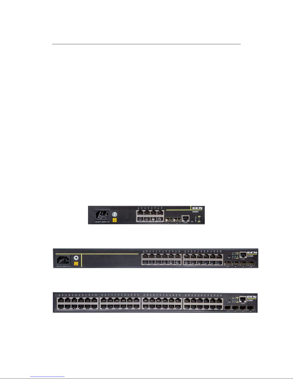
Fig 1-1 S4600-10P-SI Switch
Fig 1-2 S4600-28P-SI Switch
Fig 1-3 S4600-52P-SI Switch
Page 3
S4600 series Installation manual Chyba! Pomocí karty Domů
použijte u textu, který se má zde zobrazit, styl 标题 1. Chyba! Pomocí karty Domů
použijte u textu, který se má zde zobrazit, styl 标题 1.
1-2
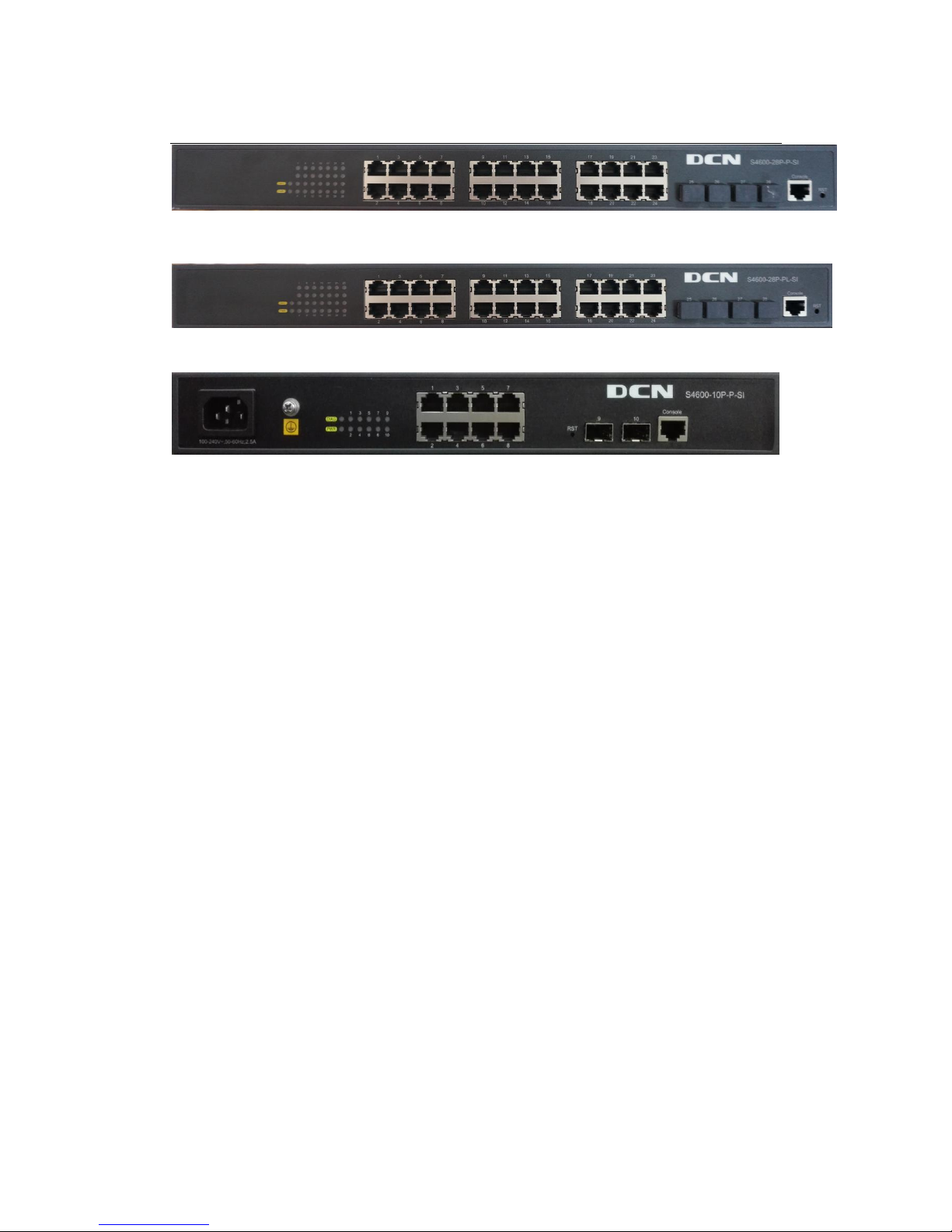
Fig 1-4 S4600-28P-P-SI Switch
Fig 1-5 S4600-28P-PL-SI Switch
Fig 1-6 S4600-10P-P-SI Switch
1.2 Physical Specifications
Management Port
1 RJ-45 serial console port
AC Power Input
90 ~ 264VAC, 47Hz ~ 63Hz
Power Consumption
S4600-10P-SI: <20W
S4600-28P-SI: <20W
S4600-52P-SI: <40W
S4600-28P-P-SI: <440W
S4600-28P-PL-SI: <230W
S4600-10P-P-SI: <150W
Operating Temperature
-5 °C~50°C
Storage Temperature
-40°C~ 70°C
Relative Humidity
5%~95%, no condensate
Dimension
S4600-10P-SI: W×H×D 250mm×180mm×43.6mm
S4600-28P-SI: W×H×D 442mm×220mm×43.6mm
Page 4
S4600 series Installation manual Chyba! Pomocí karty Domů
použijte u textu, který se má zde zobrazit, styl 标题 1. Chyba! Pomocí karty Domů
použijte u textu, který se má zde zobrazit, styl 标题 1.
1-3
S4600-52P-SI: W×H×D 442mm×220mm×43.6mm
S4600-28P-P-SI: W×H×D 440mmX280mmx43.6mm
S4600-28P-PL-SI: W×H×D 440mmX280mmx43.6mm
S4600-10P-P-SI: W×H×D 330mmX220mmx43.6mm
Weight
S4600-10P-SI: about 1.1kg
S4600-28P-SI: about 2.42kg
S4600-52P-SI: about 4.7kg
S4600-28P-P-SI: about 5.35kg
S4600-28P-PL-SI: about 4.9kg
S4600-10P-P-SI: about 3.5kg
Average no trouble time
At least 21, 0000 hours MTBF
1.3 Description of Hardware
1.3.1 Front Panel
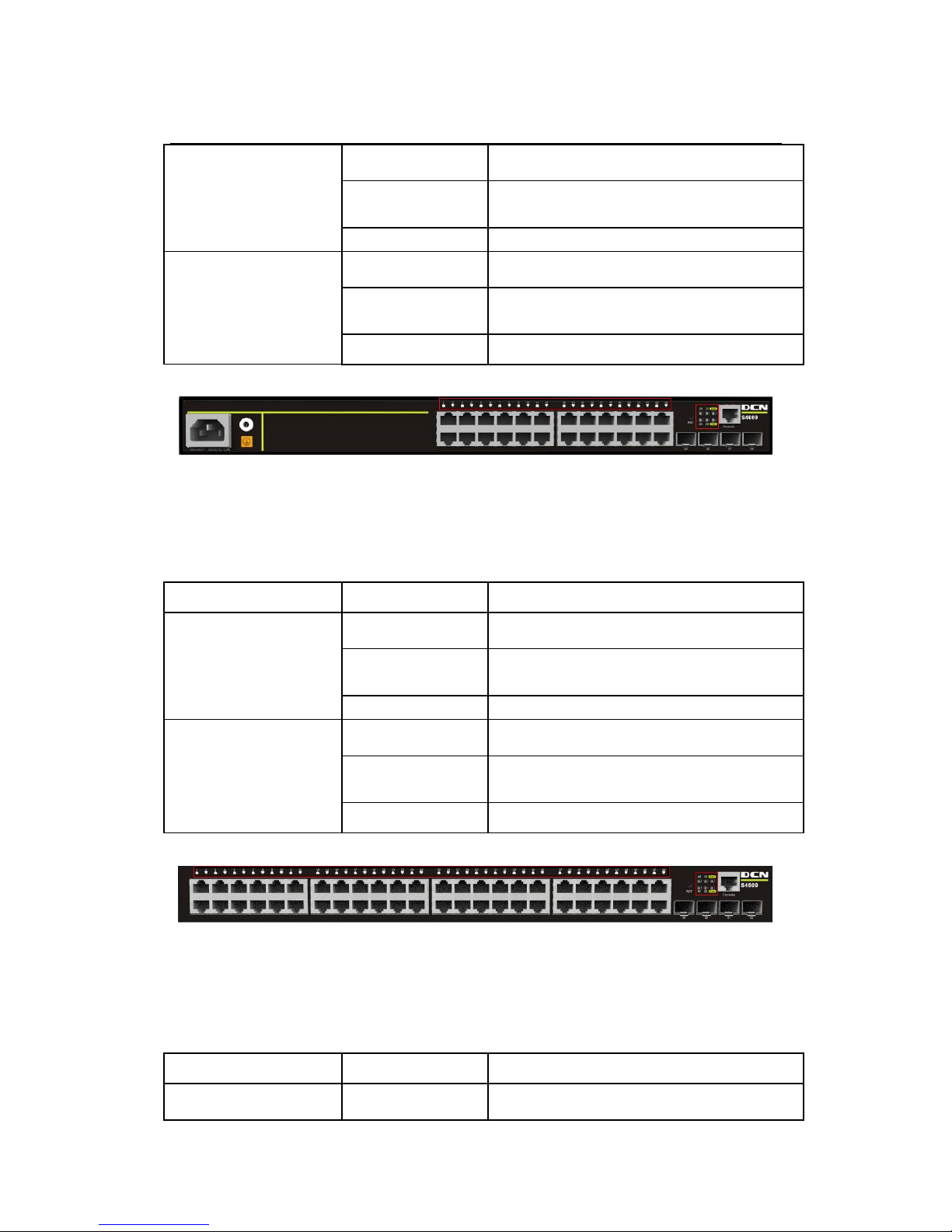
S4600-10P-SI provides 8 10/100/1000Base-T ports, 2 1000Mb SFP ports, 1 Console
port, 1 system reset button, 12 LEDs, 1 220V AC power socket and 1 grounding screw.
The front panel of S4600-10P-SI is shown as follow:
Fig1-7 Front Panel of S4600-10P-SI
S4600-28P-SI provides 24 10/100/1000Base-T ports, 4 1000Mb SFP ports, 1
Console port, 1 system reset button, 30 LEDs, 1 220V AC power socket and 1 grounding
screw.
The front panel of S4600-28P-SI is shown as follow:
Fig 1-8 Front Panel of S4600-28P-SI
S4600-52P-SI provides 48 10/100/1000Base-T ports, 4 1000Mb SFP ports, 1
Console port, 1 system reset button, 54 LEDs.
Page 5
S4600 series Installation manual Chyba! Pomocí karty Domů
použijte u textu, který se má zde zobrazit, styl 标题 1. Chyba! Pomocí karty Domů
použijte u textu, který se má zde zobrazit, styl 标题 1.
1-4
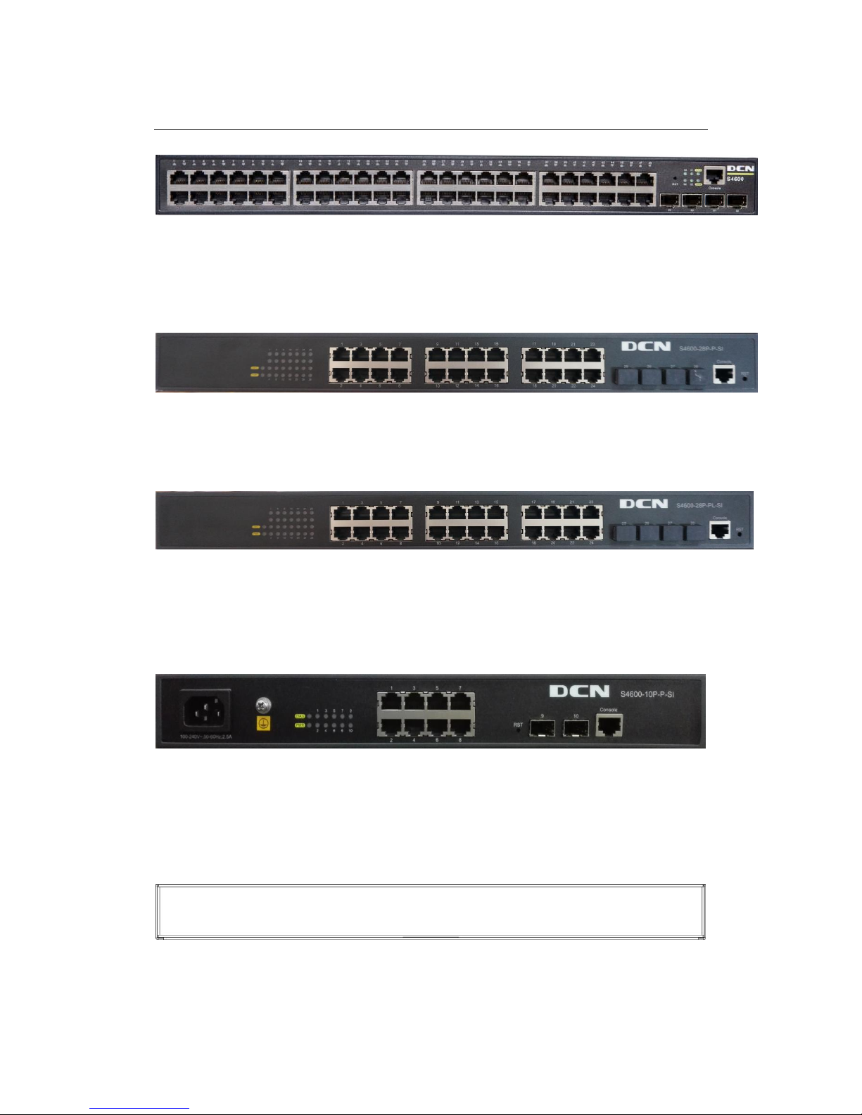
The front panel of S4600-52P-SI series is shown as follow:
Fig 1-9 Front Panel of S4600-52P-SI
S4600-28P-P-SI provides 24 10/100/1000Base-T ports, 4 1000Mb SFP ports, 1
Console port, 1 system reset button, 30 LEDs.
The front panel of S4600-28P-P-SI series is shown as follow:
Fig 1-10 Front Panel of S4600-28P-P-SI
S4600-28P-PL-SI provides 24 10/100/1000Base-T ports, 4 1000Mb SFP ports, 1
Console port, 1 system reset button, 30 LEDs.
The front panel of S4600-28P-PL-SI series is shown as follow:
Fig 1-11 Front Panel of S4600-28P-PL-SI
S4600-10P-P-SI provides 8 10/100/1000Base-T ports, 2 1000Mb SFP ports, 1
Console port, 1 system reset button, 12 LEDs, 1 220V AC power socket and 1 grounding
screw.
The front panel of S4600-10P-P-SI series is shown as follow:
Fig 1-12 Front Panel of S4600-10P-P-SI
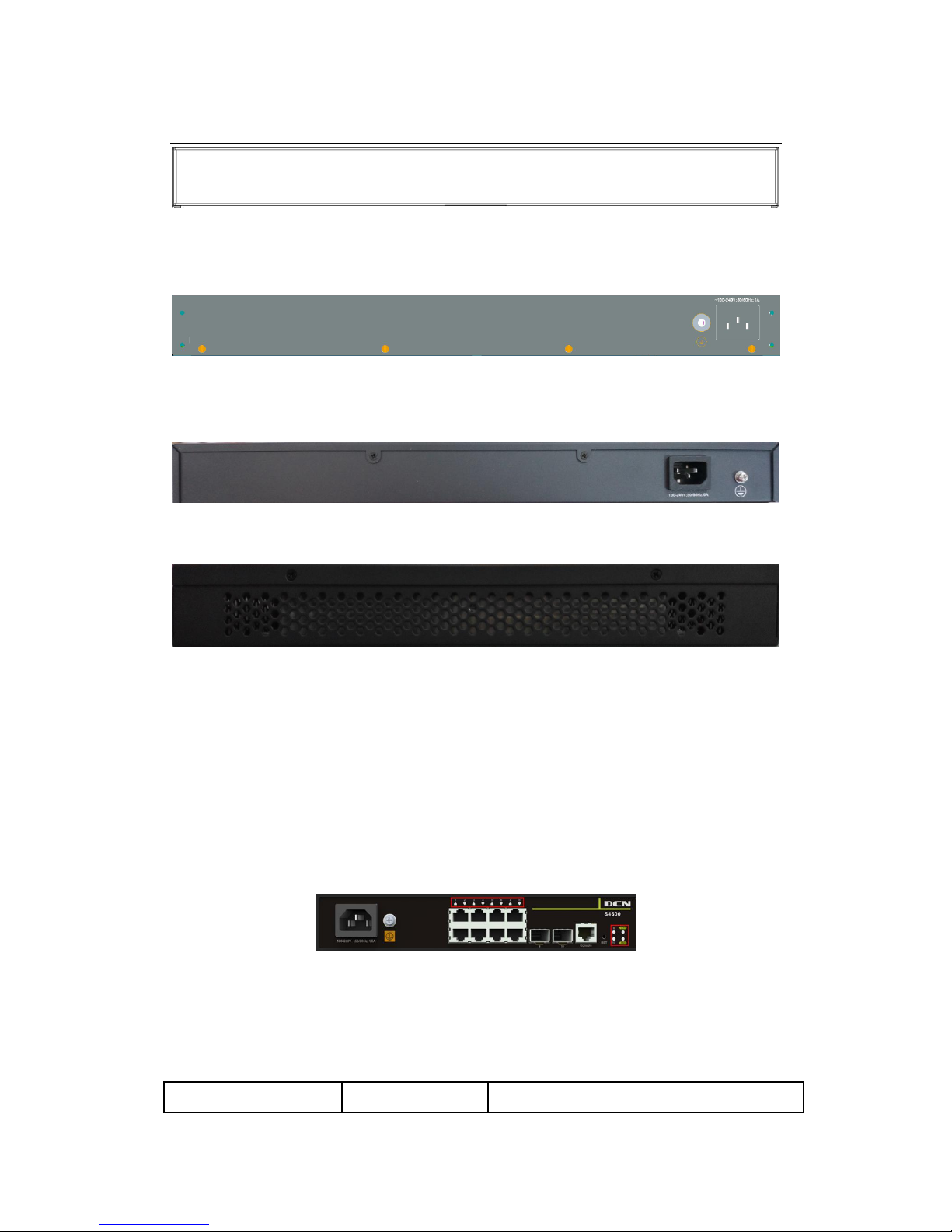
1.3.2 Back Panel
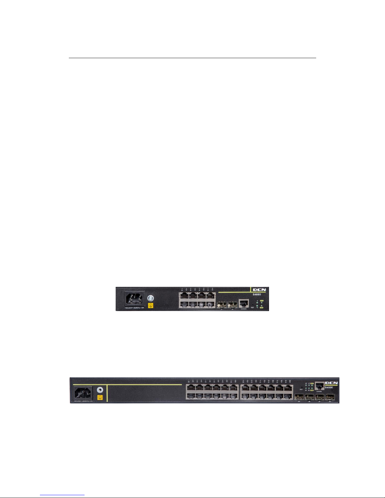
The back panel of S4600-10P-SI is shown below:
Fig 1-13 Back Panel of S4600-10P-SI
The back panel of S4600-28P-SI is shown below:
Page 6
S4600 series Installation manual Chyba! Pomocí karty Domů
použijte u textu, který se má zde zobrazit, styl 标题 1. Chyba! Pomocí karty Domů
použijte u textu, který se má zde zobrazit, styl 标题 1.
1-5
Fig 1-14 Back Panel of S4600-28P-SI
The back panel of S4600-52P-SI is shown below, and there is 1 220V AC power
socket and 1 ground screw hole.
Fig 1-15 Back Panel of S4600-52P-SI
The back panel of S4600-28P-P-SI/S4600-28P-PL-SI is shown below, and there is 1
220V AC power socket and 1 ground screw hole.
Fig 1-16 Back Panel of S4600-28P-P-SI/S4600-28P-PL-SI
The back panel of S4600-10P-P-SI is shown below:
Fig 1-17 Back Panel of S4600-10P-P-SI
1.3.3 Status LEDs
S4600 series switches include port indicator and system status indicator, as shown in
below and described in the following table.
1.3.3.1 Port Indicator Description
Fig 1-18 S4600-10P-SI LED diagram
Table 1-1 S4600-10P-SI port indicator description
Panel Symbol
Status
Description
Page 7
S4600 series Installation manual Chyba! Pomocí karty Domů
použijte u textu, který se má zde zobrazit, styl 标题 1. Chyba! Pomocí karty Domů
použijte u textu, který se má zde zobrazit, styl 标题 1.
1-6
Port1-8(Link/Act)
On (Green)
The port is linked successfully
Flash (Green)
The port is linked successfully, and
receive/send data
Off
The port is not link
Port9/10(Link/Act)
On (Green)
SFP port is linked successfully
Flash (Green)
SFP port is linked successfully, and
receive/send data
Off
SFP port is not link
Fig 1-19 S4600-28P-SI LED diagram
Table 1-2 S4600-28P-SI port indicator description
Panel Symbol
Status
Description
Port1-24(Link/Act)
On (Green)
The port is linked successfully
Flash (Green)
The port is linked successfully, and
receive/send data
Off
The port is not link
Port25-28(Link/Act)
On (Green)
SFP port is linked successfully
Flash (Green)
SFP port is linked successfully, and
receive/send data
Off
SFP port is not link
Fig 1-20 S4600-52P-SI LED diagram
Table 1-3 S4600-52P-SI port indicator description
Panel Symbol
Status
Description
Port1-48(Link/Act)
On (Green)
The port is linked successfully
Page 8

S4600 series Installation manual Chyba! Pomocí karty Domů
použijte u textu, který se má zde zobrazit, styl 标题 1. Chyba! Pomocí karty Domů
použijte u textu, který se má zde zobrazit, styl 标题 1.
1-7
Flash (Green)
The port is linked successfully, and
receive/send data
Off
The port is not link
Port49-52(Link/Act)
On (Green)
SFP port is linked successfully
Flash (Green)
SFP port is linked successfully, and
receive/send data
Off
SFP port is not link
Fig 1-21 S4600-28P-P-SI LED diagram
Table 1-4 S4600-28P-P-SI port indicator description
Panel Symbol
Status
Description
Port1-24(Link/Act)
On (Green)
The port is linked successfully or PD
connected successfully
Flash (Green)
The port is linked successfully, and
receive/send data
Off
The port is not link and PD not connected
Port25/26/27/28(Link/A
ct)
On (Green)
SFP port is linked successfully
Flash (Green)
SFP port is linked successfully, and
receive/send data
Off
SFP port is not link
Fig 1-22 S4600-28P-PL-SI LED diagram
Table 1-5 S4600-28P-PL-SI port indicator description
Panel Symbol
Status
Description
Port1-24(Link/Act)
On (Green)
The port is linked successfully or PD
connected successfully
Page 9

S4600 series Installation manual Chyba! Pomocí karty Domů
použijte u textu, který se má zde zobrazit, styl 标题 1. Chyba! Pomocí karty Domů
použijte u textu, který se má zde zobrazit, styl 标题 1.
1-8
Flash (Green)
The port is linked successfully, and
receive/send data
Off
The port is not link and PD not connected
Port25/26/27/28(Link/A
ct)
On (Green)
SFP port is linked successfully
Flash (Green)
SFP port is linked successfully, and
receive/send data
Off
SFP port is not link
Fig 1-23 S4600-10P-P-SI LED diagram
Table 1-6 S4600-10P-P-SI port indicator description
Panel Symbol
Status
Description
Port 1-8(Link/Act)
On (Green)
The port is linked successfully or PD
connected successfully
Flash (Green)
The port is linked successfully, and
receive/send data
Off
The port is not link and PD not
connected
Port 9/10(Link/Act)
On (Green)
The port is linked successfully
Flash (Green)
The port is linked successfully, and
receive/send data
Off
The port is not link
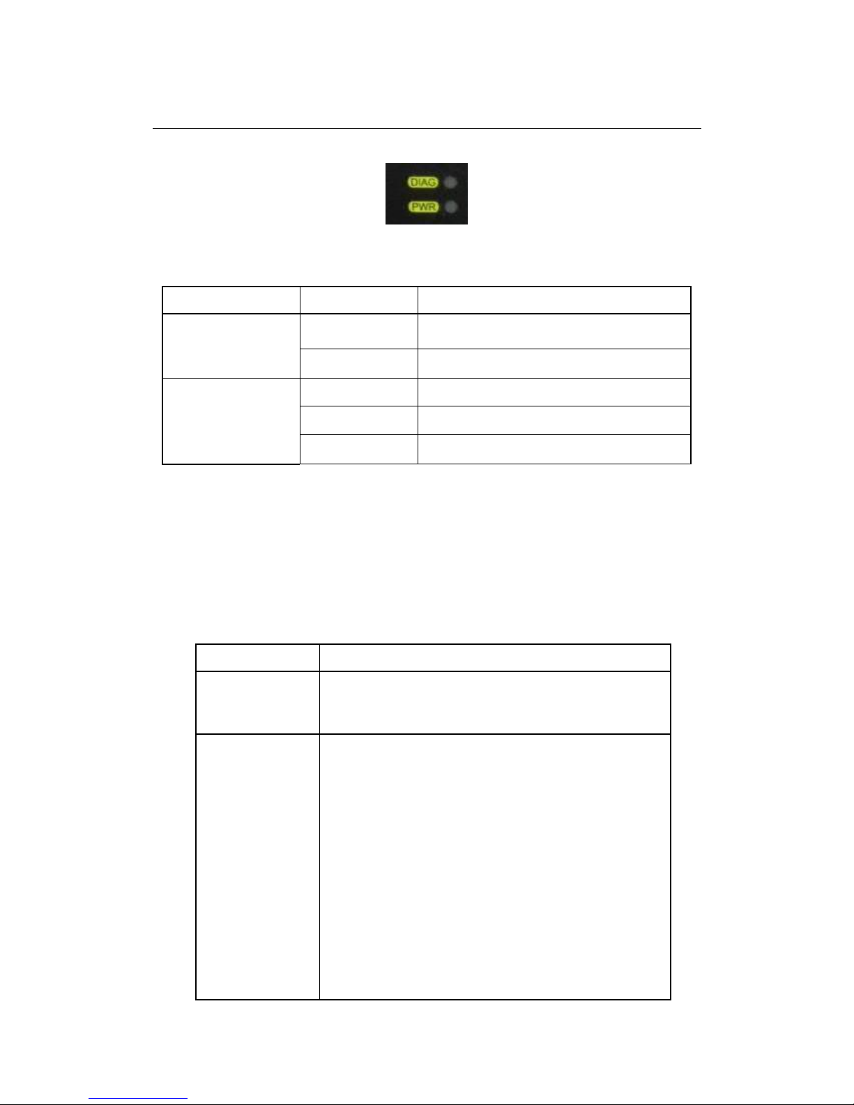
1.3.3.2 System Status Indicator Description
Fig 1-24 S4600-10P-SI system LED diagram
Table 1-7 S4600-10P-SI system indicator description
Page 10

S4600 series Installation manual Chyba! Pomocí karty Domů
použijte u textu, který se má zde zobrazit, styl 标题 1. Chyba! Pomocí karty Domů
použijte u textu, který se má zde zobrazit, styl 标题 1.
1-9
LED
Status
Description
Power
On (Green)
The internal power is operating normally
Off
Power is off or error
DIAG
On (Green)
Operating state is abnormal
Flash(Green)
Operating state is normal
Off
Power is off or system is abnormal
Fig 1-25 S4600-28P-SI system LED diagram
Table 1-8 S4600-28P-SI system indicator description
LED
Status
Description
Power
On (Green)
The internal power is operating normally
Off
Power is off or error
DIAG
On (Green)
Operating state is abnormal
Flash(Green)
Operating state is normal
Off
Power is off or system is abnormal
Fig 1-26 S4600-52P-SI system LED diagram
Table 1-9 S4600-52P-SI system indicator description
LED
Status
Description
Power
On (Green)
The internal power is operating normally
Off
Power is off or error
DIAG
On (Green)
Operating state is abnormal
Page 11

S4600 series Installation manual Chyba! Pomocí karty Domů
použijte u textu, který se má zde zobrazit, styl 标题 1. Chyba! Pomocí karty Domů
použijte u textu, který se má zde zobrazit, styl 标题 1.
1-10
Flash(Green)
Operating state is normal
Off
Power is off or system is abnormal
Fig 1-27 S4600-28P-P-SI system LED diagram
Table 1-10 S4600-28P-P-SI system indicator description
LED
Status
Description
Power
On (Green)
The internal power is operating normally
Off
Power is off or error
DIAG
On (Green)
Operating state is abnormal
Flash(Green)
Operating state is normal
Off
Power is off or system is abnormal
Fig 1-28 S4600-28P-PL-SI system LED diagram
Table 1-11 S4600-28P-PL-SI system indicator description
LED
Status
Description
Power
On (Green)
The internal power is operating normally
Off
Power is off or error
DIAG
On (Green)
Operating state is abnormal
Flash(Green)
Operating state is normal
Off
Power is off or system is abnormal
Page 12
S4600 series Installation manual Chyba! Pomocí karty Domů
použijte u textu, který se má zde zobrazit, styl 标题 1. Chyba! Pomocí karty Domů
použijte u textu, který se má zde zobrazit, styl 标题 1.
1-11
Fig 1-29 S4600-10P-P-SI system LED diagram
Table 1-12 S4600-10P-P-SI system indicator description
LED
Status
Description
PWR
On (Green)
The internal power is operating normally
Off
Power is off or error
DIAG
On (Green)
Operating state is abnormal
Flash(Green)
Operating state is normal
Off
Power is off or system is abnormal
1.3.4 Front Panel Port Description
Each port description is shown below:
Table 1-13 S4600 port description
Interface mode
Spec
RJ-45 port
10/100/1000Mbps auto negotiation
MDI/MDI-X cable mode auto negotiation
5 kinds of UTP: 100 m
SFP
SFP-SX-L transceiver
1000Base-SX SFP(850nm, MMF, 550m)
SFP-LX-L transceiver
1000Base-LX SFP(1310nm, SMF, 10km or MMF,
550m)
SFP-LX-20-L transceiver
1310nm lightwave, 9/125um single mode fiber:
20km
SFP-LX-40 transceiver
9/125um single mode fiber: 40km
SFP-LH-70-L transceiver
9/125um single mode fiber: 70km
SFP-LH-120-L transceiver
9/125um single mode fiber: 120km
Page 13

S4600 series Installation manual Chyba! Pomocí karty Domů
použijte u textu, který se má zde zobrazit, styl 标题 1. Chyba! Pomocí karty Domů
použijte u textu, který se má zde zobrazit, styl 标题 1.
1-12
Page 14

S4600 series Installation manual Chyba! Pomocí karty Domů použijte u
textu, který se má zde zobrazit, styl 标题 1. Chyba! Pomocí karty Domů použijte u textu,
který se má zde zobrazit, styl 标题 1.
2-1
Chapter 2 Hardware Installation
2.1 Installation Notice
To ensure the proper operation of S4600 series and your physical security, please
read carefully the following installation guide.
2.1.1 Environmental Requirements
The switch must be installed in a clean area. Otherwise, the switch may be damaged
by electrostatic adherence.
Maintain the temperature and the humidity within the set environment.
The switch must be put in a dry and cool place. Leave sufficient spacing around the
switch for good air circulation.
The switch must work in the right range of power input.
The switch must be well grounded in order to avoid ESD damage and physical injury
of people.
The switch should avoid the sunlight perpendicular incidence. Keep the switch away
from heat sources and strong electromagnetic interference sources.
The switch must be mounted to a standard 19’’ rack or placed on a clean level
desktop.
2.1.1.1 Dust and Particles
Dust is harmful to the safe operation of switch. Dust can lead to electrostatic
adherence, especially likely under low relative humidity, causing poor contact of metal
connectors or contacts. Electrostatic adherence will result in not only reduced product
lifespan, but also increased chance of communication failures. The recommended value
for dust content and particle diameter in the site is shown below:
Max Diameter (µm)
0.5 1 3
5
Max Density
(particles/m³)
1.4×10⁵
7×10⁵
2.4×10⁵
1.3×10⁵
Table 2-1 Environmental Requirements: Dust content
In addition, salt, acid and sulfide in the air are also harmful to the switch. Such
Page 15

S4600 series Installation manual Chyba! Pomocí karty Domů použijte u
textu, který se má zde zobrazit, styl 标题 1. Chyba! Pomocí karty Domů použijte u textu,
který se má zde zobrazit, styl 标题 1.
2-2
harmful gases will aggravate metal corrosion and the aging of some parts. The site should
avoid harmful gases, such as SO2, H2S, NO2, NH3 and Cl2, etc. The table below details
the threshold value.
Gas
Average (mg/m³)
Max (mg/m³)
SO2
0.2
1.5
H2S
0.006
0.03
NO2
0.04
0.15
NH3
0.05
0.15
Cl2
0.01
0.3
Table 2-2 Environmental Requirements: Particles
2.1.1.2 Temperature and Humidity
The switch installation site should maintain a desirable temperature and humidity.
High-humidity conditions can cause electrical resistance degradation or even electric
leakage, degradation of mechanical properties and corrosion of internal components.
Extreme low relative humidity may cause the insulation spacer to contract, making the
fastening screw insecure. Furthermore, in dry environments, static electricity is liable to be
produced and cause harm to internal circuits. Temperature extremes can cause reduced
reliability and premature aging of insulation materials, thus reducing the switch’s working
lifespan. In the hot summer, it is recommended to use air-conditioners to cool down the
site. And the cold winter, it is recommenced to use heaters. The recommended
temperature and humidity are shown below:
Temperature:
Relative humidity
Long term
condition
Short term
condition
Long term
condition
Short term
condition
15~30℃
-10~50℃
40~65%
5% ~95%
Table 2-3 Environmental Requirements: Temperature and Humidity
Caution!
A sample of ambient temperature and humidity should be taken at 1.5m above the
floor and 0.4m in front of the switch rack, with no protective panel covering the front and
rear of the rack. Short term working conditions refer to a maximum of 48 hours of
continued operation and an annual cumulative total of less than 15 days. Formidable
operation conditions refers to the ambient temperature and relative humidity value that
may occur during an air-conditioning system failure, and normal operation conditions
Page 16

S4600 series Installation manual Chyba! Pomocí karty Domů použijte u
textu, který se má zde zobrazit, styl 标题 1. Chyba! Pomocí karty Domů použijte u textu,
který se má zde zobrazit, styl 标题 1.
2-3
should be recovered within 5 hours.
2.1.1.3 Power Supply
It is adopted module switch power for the switch, the input parameters of power are
shown below:
The AC input voltage: 90~300VAC
The frequency: 47Hz ~ 63Hz
The DC input voltage: 12V/3.3A
Before powering on the power supply, please check the input power to ensure proper
grounding of the power supply system. The input power for the switch should be reliable
and secure; a voltage adaptor can be used if necessary. The building’s circuit protection
system should include in the circuit a fuse or circuit-breaker of no greater than 240 V, 10 A.
It is recommended to use a UPS for more reliable power supplying. .
Caution!
Improper power supply system grounding, extreme fluctuation of the input source,
and transients (or spikes) can result in larger error rate, or even hardware damage!
2.1.1.4 Preventing Electrostatic Discharge Damage
Static electric can cause damage to internal circuits, even the entire switch. Follow
these guidelines for avoiding ESD damage:
Ensure proper earth grounding of the device;
Perform regular cleaning to reduce dust;
Maintain proper temperature and humidity;
Always wear an ESD wrist strap and antistatic uniform when in contact with circuit
boards.
2.1.1.5 Anti-interference
All sources of interference, whether from the device/system itself or the outside
environment, will affect operations in various ways, such as capacitive coupling, inductive
coupling, electromagnetic radiation, common impedance (including the grounding system)
and cables/lines (power cables, signal lines, and output lines). The following should be
noted:
Precautions should be taken to prevent power source interruptions;
Provide the system with a dedicated grounding, rather than sharing the grounding
Page 17

S4600 series Installation manual Chyba! Pomocí karty Domů použijte u
textu, který se má zde zobrazit, styl 标题 1. Chyba! Pomocí karty Domů použijte u textu,
který se má zde zobrazit, styl 标题 1.
2-4
with the electronic equipment or lightning protection devices.
Keep away from high power radio transmitters, radar transmitters, and high frequency
strong circuit devices.
Provide electromagnetic shielding if necessary.
2.1.1.6 Rack Configuration
The dimension of the switch is designed to be mounted on a standard 19’’ rack.
Please ensure good ventilation for the rack.
Every device in the rack will generate heat during operation, therefore vent and fans
must be provided for an enclosed rack, and devices should not be stacked closely.
When mounting devices in an open rack, care should be taken to prevent the rack
frame from obstructing the switch ventilation openings. Be sure to check the
positioning of the switch after installation to avoid the aforementioned.
Caution!
If a standard 19’’ rack is not available, the switch can be placed on a clean level
desktop, leave a clearance of 10mm around the switch for ventilation, and do not place
anything on top of the switch.
2.1.2 Installation Notice
Read through the installation instruction carefully before operating on the system.
Make sure the installation materials and tools are prepared. And make sure the
installation site is well prepared.
During the installation, users must use the brackets and screws provided in the
accessory kit. Users should use the proper tools to perform the installation. Users
should always wear antistatic uniform and ESD wrist straps. Users should use
standard cables and connecters.
After the installation, users should clean the site. Before powering on the switch,
users should ensure the switch is well grounded. Users should maintain the switch
regularly to extend the lifespan of the switch.
2.1.3 Security Warnings
When using SFP transceiver, do not stare directly at the fiber bore when the switch is
in operation. Otherwise the laser may hurt your eyes.
Page 18

S4600 series Installation manual Chyba! Pomocí karty Domů použijte u
textu, který se má zde zobrazit, styl 标题 1. Chyba! Pomocí karty Domů použijte u textu,
který se má zde zobrazit, styl 标题 1.
2-5
Do not attempt to conduct the operations which can damage the switch or which can
cause physical injury.
Do not install, move or disclose the switch and its modules when the switch is in
operation.
Do not open the switch shell.
Do not drop metals into the switch. It can cause short-circuit.
Do not touch the power plug and power socket.
Do not place the tinder near the switch.
Do not configure the switch alone in a dangerous situation.
Use standard power sockets which have overload and leakage protection.
Inspect and maintain the site and the switch regularly.
Have the emergence power switch on the site. In case of emergence, switch off the
power immediately.
According to the require of standard GB9254-2008 information technology equipment
radio disturbance limits and methods of measurement, information technology
equipment divided into A level ITE and B level ITE.
A level ITE is the information technology equipment that satisfied A level limit but not
satisfied B level limit.
Note: For this king of equipment, the sales should not be limited but it must includes
the following statement in related direction for use.
Warning
This is class A product. In a domestic environment this product may cause radio
interference in which case the user may be required to take adequate measures.
Caution!
Potential risk include: Electric leakage, Power supply arcing, Power line breakage,
Imperfect earth, Overload circuit and Electrical short circuit..If electric shock, fire, electrical
short circuit occurs, please cut off the electricity supply and alarm rapidly. Rescue the
injured person in the contingency under inherently safe, give the injured person proper
first aid treatment according to the injury state, and seek help from the Medical
Emergency using various ways.
2.2 Installation Preparation
2.2.1 Verify the Package Contents
Page 19
S4600 series Installation manual Chyba! Pomocí karty Domů použijte u
textu, který se má zde zobrazit, styl 标题 1. Chyba! Pomocí karty Domů použijte u textu,
který se má zde zobrazit, styl 标题 1.
2-6
First, open the package, please check the contents of the switch container and
accessory kit. (If you are concerned that any item is missing or an incorrect item has been
supplied, please contact your dealer as soon as possible.)
2.2.2 Required Tools and Materials
The required tools and utilities are shown below:
Cross screwdrivers
Flat-blade screwdriver
ESD wrist strap
Antistatic uniform
Caution!
Users should prepare the required tools by themselves.
2.3 Installation Guide
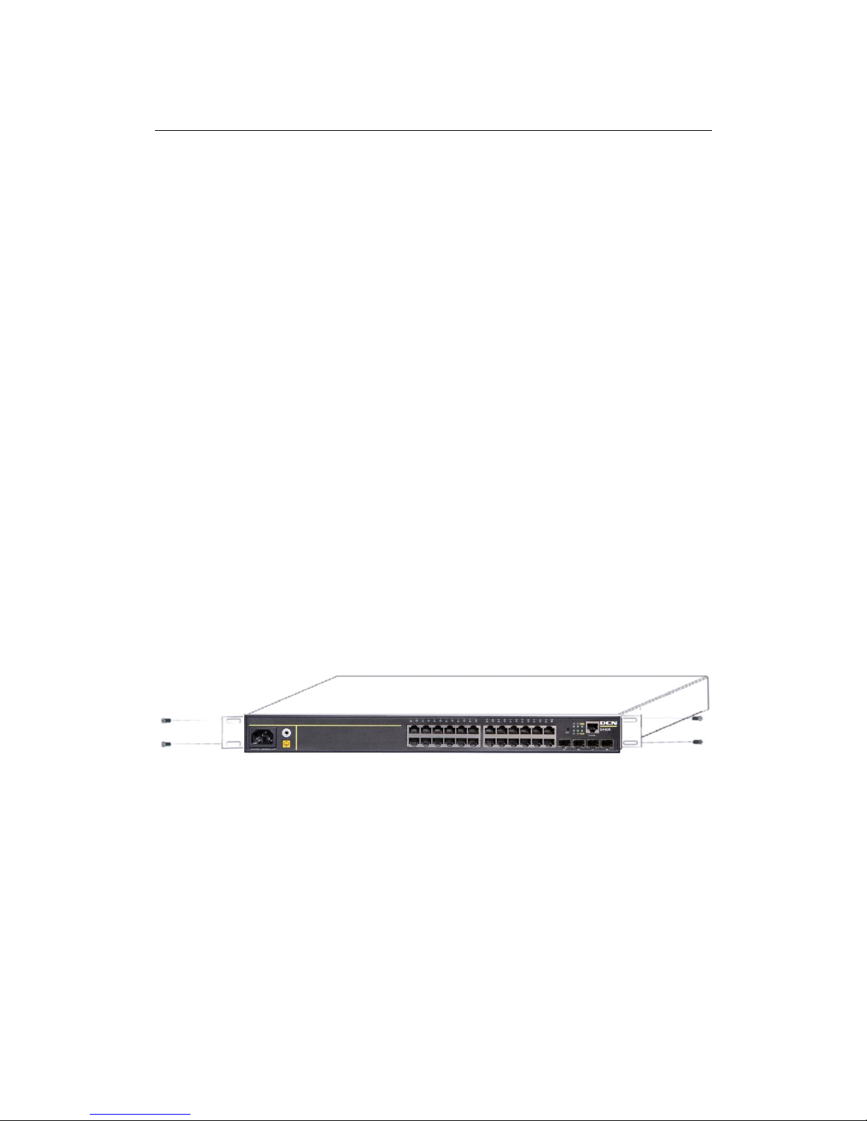
2.3.1 Installing the Switch
Please mount the switch as below:
1. Attach the 2 brackets on the switch with screws provided in the accessory kit.
Fig 2-1 Fasten the Brackets to the Switch
2. Put the bracket-mounted switch smoothly into a standard 19’’ rack. Fasten the
switch to the rack with the screws provided. Leave enough space around the switch for
good air circulation.
Page 20

S4600 series Installation manual Chyba! Pomocí karty Domů použijte u
textu, který se má zde zobrazit, styl 标题 1. Chyba! Pomocí karty Domů použijte u textu,
který se má zde zobrazit, styl 标题 1.
2-7
Fig 2-2 Fasten the Switch to the Rack
Caution!
The brackets are used to fix the switch on the rack. They can’t serve as a bearing.
Please place a rack shelf under the switch. Do not place anything on top of the switch. Do
not block the blowholes on the switch to ensure the proper operation of the switch.
2.3.2 Connecting Console
S4600 series provide a RJ45 serial console port.
Fig 2-3 Connecting Console to switch
The connection procedure is listed below:
1. Find the console cable provided in the accessory kit. Attach the RJ45 end to console
port of the switch.
2. Connect the other side of the console cable to a character terminal (PC).
3. Power on the switch and the character terminal. Configure the switch through the
character terminal.
Page 21

S4600 series Installation manual Chyba! Pomocí karty Domů použijte u
textu, který se má zde zobrazit, styl 标题 1. Chyba! Pomocí karty Domů použijte u textu,
který se má zde zobrazit, styl 标题 1.
2-8
2.3.3 SFP Transceiver Installation
S4600 series provide multiple 1000Mb SFP transceiver slots.
The procedure for installing the SFP transceiver is shown below:
Step 1: Put on a ESD wrist strap (or antistatic gloves)
Step 2: Insert the SFP transceiver to the guide rail inside the fiber interface line card.
Do not put the SFP transceiver up-side-down.
Step 3: Push the SFP transceiver along the guide rail gently until you feel the
transceiver snap into place at the bottom of the line card.
Note: The SFP transceiver is hot swappable.
Caution!
Do not stare directly at the 2 fiber bore in the SFP transceiver when the switch is in
operation, otherwise the laser may hurt your eyes.
2.3.4 Copper Cable/Fiber Cable Connection
Copper cables should be connected as below:
Step 1: Insert one end of the Ethernet cable to the RJ-45 Ethernet port in the switch
copper cable line card;
Step 2: Insert the other end of the Ethernet cable to the RJ-45 Ethernet port of other
device;
Step 3: Check all status indicators for the corresponding ports; a lighted LED indicates
that the link has been established, otherwise the link is not ready and the cable should be
examined.
Caution!
Please verify the sign above the port to ensure using the right port. Connecting to
wrong ports might damage the switch.
Fiber cables should be connected as below:
Step 1: Remove the protective plug from the SFP/XFP fiber transceiver bore; Remove
the protective cap from one end of the fiber cable. Keep the fiber end clean and neat.
Step 2: Attach one end of the fiber cable to the SFP/XFP transceiver, and attach the
other end to the transceiver of the corresponding devices. Note: The SFP/XFP
transceiver’s TX port should be connected to the RX port of the corresponding
Page 22

S4600 series Installation manual Chyba! Pomocí karty Domů použijte u
textu, který se má zde zobrazit, styl 标题 1. Chyba! Pomocí karty Domů použijte u textu,
který se má zde zobrazit, styl 标题 1.
2-9
device, and vice versa.
Step 3: Check the fiber port status indicator, a lighted LED indicates that the link has
been established; otherwise the link is not ready and should be examined.
Caution!
Please verify the sign above the port to ensure using the other ports. Connecting to
wrong ports might damage the transceiver or the other ports. When connecting other
devices through a fiber cable to the switch, the output power of the fiber cable must not
exceed the maximum received power of the corresponding modules. Otherwise, it will
damage the fiber transceiver. Do not stare at the fiber bore when the switch is in operation.
That may hurt your eyes.
2.3.5 Power Supply Connection
S4600 series use the power is 220VAC. Please read the power input specification for
the detailed information.
Power supply connection procedure is described as below:
Fig 2-4 Connecting power to switch
1. Insert one end of the power cable provided in the accessory kit into the power source
socket (with overload and leakage protection), and the other end to the power socket in
the back panel of the switch.
2. Check the power status indicator in the front panel of the switch. The corresponding
power indicator should light. S4600 series is self-adjustable for the input voltage. As soon
as the input voltage is in the range printed on the switch surface, the switch can operate
correctly.
3. When the switch is powered on, it executes self-test procedure and startups.
Caution!
The input voltage must be within the required range, otherwise the switch can be
damaged or malfunction. Do not open the switch shell without permission. It can cause
physical injury.
 Loading...