

DCN DCS-3950-10C, DCS-3950-10C-R, DCS-3950-26C, DCS-3950-28C, DCS-3950-28C-R Installation Manual
...Page 1

DCS-3950 series Installation manual Content
1
Content
Chapter 1 Introduct ion ............................................................. 1-1
1.1 Pro duct Brief ...................................................................................... 1-1
1.1.1 Overview ..................................................................................................1-1
1.1.2 Features and Benefits .............................................................................1-2
1.2 Physic al Specif ic ati ons .................................................................... 1-3
1.3 Descr i p ti o n of Har d ware
.................................................................. 1-3
1.3.1 Front Panel ...............................................................................................1-3
1.3.2 Back Panel ...............................................................................................1-4
1.3.3 Status LEDs .............................................................................................1-5
1.3.4 Front Panel Port Description .................................................................1-8
Chapter 2 Hard ware Installation .............................................. 2-1
2.1 Installation Notice ............................................................................. 2-1
2.1.1 Environmental Requirements ................................................................2-1
2.1.2 Installation Notice ...................................................................................2-4
2.1.3 Security Warnings ...................................................................................2-4
2.2 Installation Preparation .................................................................... 2-5
2.2.1 Verify the Package Contents ..................................................................2-5
2.2.2 Required Tools and Materials ................................................................2-5
2.3 Installation Guide .............................................................................. 2-6
2.3.1 Installing the Switch ...............................................................................2-6
2.3.2 Switch grounding ....................................................................................2-6
2.3.3 Connecting Console ...............................................................................2-7
2.3.4 SFP Transceiver Installation ..................................................................2-8
2.3.5 Copper Cable/Fiber Cable Connection .................................................2-8
2.3.6 AC Power Supply Connecti on ...............................................................2-9
2.3.7 DC Power Supply Connection .............................................................2-10
Page 2
DCS-3950 series Installation manual Chapter 1 Introduction
1-1
Chapter 1 Introduction
1.1 Product Brief
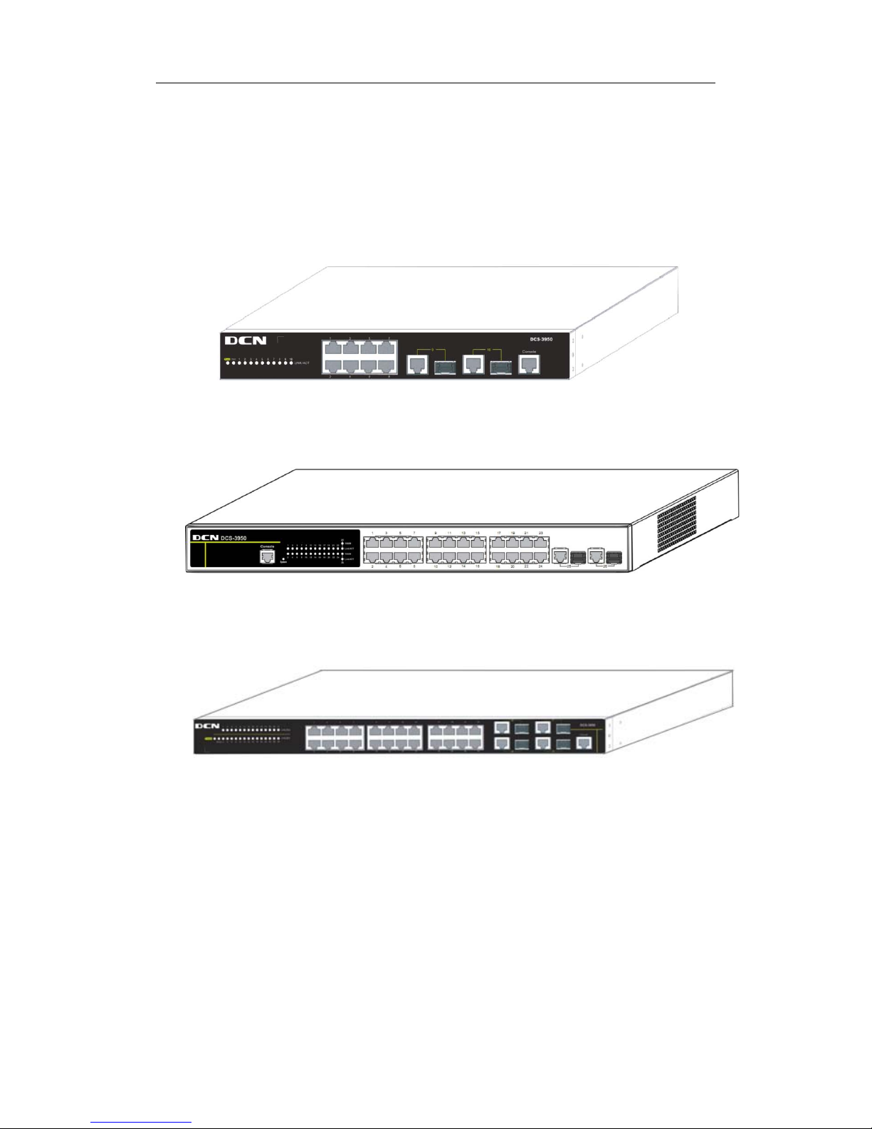
DCS-3950-10C series switches:
Fig 1-1 DCS-3950-10C/DCS-3950-10C-R/DCS-3950-10C-DC switch
DCS-3950-26C switch:
Fig 1-2 DCS-3950-26C switch
DCS-3950-28C series switches:
Fig 1-3 DCS-3950-28C/DCS-3950-28C-R/DCS-3950-28C-DC switch
1.1.1 Overview
DCS-3950 series switches are 100Mb and 1000Mb layer 2 switch. DCS-3950-10C
series provide 10 fi xed ports ( 8 10/100Base-T f ixed ports and 2 1000Mb COMBO ports).
DCS-3950-26C provides 26 fixed ports (24 10/100Base-T fixed ports and 2 1000Mb
COMBO ports). DCS-3950-28C series provide 28 fixed ports (24 10/100Base-T fixed
ports and 4 1000 Mb C O MBO ports ). DCS-3950 series switches with advanced intel ligent
and secure features, can serve ideally as distribution layer switches for the access device
Page 3

DCS-3950 series Installation manual Chapter 1 Introduction
1-2
of campus networks, enterprise networks and IP metropolitan networks.
1.1.2 Features and Benefits
Various Interfaces
DCS-3950 series switches provide multiple fixed 10/100Base-t ports and SFP
COM BO ports.
Network ing Prot oc ols
DCS-3950 series switches support 802.1d/w/s, 802.1Q, 802.1p, 802.3ad, 802.3x,
GVRP, DHCP and SNTP etc.
ACL
DCS-3950 series switches s upport com pr ehensi vely ACL polic ies . T he traffic can b e
classified by source/destination IP addresses, source/destination MAC addresses, IP
protocols, T CP/UDP, IP precedenc e, time ranges and ToS. And various pol icies can be
conducted to forward th e traffic . By impl ementi ng ACL policies , users can fil ter the virus
packets suc h as “Worm.Blaster” , “Worm .Sasser” and “Red Code” etc . DCS-3950 series
switches also support IEEE802.1x port based access authentication, which can be
deployed with RADIUS, to ensure the port level security and block illegal users.
QoS
DCS-3950 series switches fully support DiffServ Module. Each port provides four
priority queue, W RR/SP/SWRR scheduling is als o supported. DCS-3950 series support
the port secur it y. User s can de plo y trusted CoS, DSCP, IP precedenc e, port pri ority and
modify packets’ DSCP, COS values.
3D-SMP Ready
DCS-3950 series are up to the mustard of Self-defending security region
management str ateg y acc ordi ng to Di gital Chi na Netwar e. It is s upporte d i nter acti on wi th
some s ecurity s ystem suc h as firewall, IDS, etc. It can defense the vir us and aggress
effectively from the e xtranet and internet. Thus enhance the securi ty and stabil ity of the
network-wide.
Perfect Web Management.
DCS-3950 seri es support SN MP, In-ban d and Out-of band Manag ement, CLI and
WEB interface and RMON. It can mail the correlative sensitive information to the
administrator abide by SMTP protocol. DCS-3950 series suppor t SSH protocol; ensure
the configuration management security of the switch. It is adopted the Digital China
centrali zed web managem ent system ‘Link Manager’ for unifi ed managem ent expediently
and compactly.
Page 4

DCS-3950 series Installation manual Chapter 1 Introduction
1-3
1.2 Physical Specifications
Management Port
1 RJ-45 serial console port
AC Power Input
DCS-3950-10C series: 100V ~ 240V, 50Hz ~ 60Hz
DCS-3950-26C: 100V ~ 240V, 47Hz ~ 63Hz
DCS-3950-28C series: 100V ~ 240V, 50Hz ~ 60Hz
Power Consumption
DCS-3950-10C series: <15W
DCS-3950-26C: 20W
DCS-3950-28C series: <20W
Operating Temperature
DCS-3950-10C series: 0°C~50°C
DCS-3950-26C: -5 °C~50°C
DCS-3950-28C series: 0°C~50°C
Storage Temperature
-40°C~ 70°C
Relative Humidi ty
DCS-3950-10C series: 5%~95%, no condensate
DCS-3950-26C: 10% ~90%
DCS-3950-28C series: 5%~95%, no condensate
Dimension
DCS-3950-10C series: W×H×D 282.2mm×44mm×178mm
DCS-3950-26C: W×H×D 430mm×44.45mm×170mm
DCS-3950-28C series: W×H×D 442.9mm×44mm×230.4mm
Weight
DCS-3950-10C series: about 4kg
DCS-3950-26C: 1960g (no packing)
DCS-3950-28C series: about 4.5kg
1.3 Description of Hardware
1.3.1 Front Panel
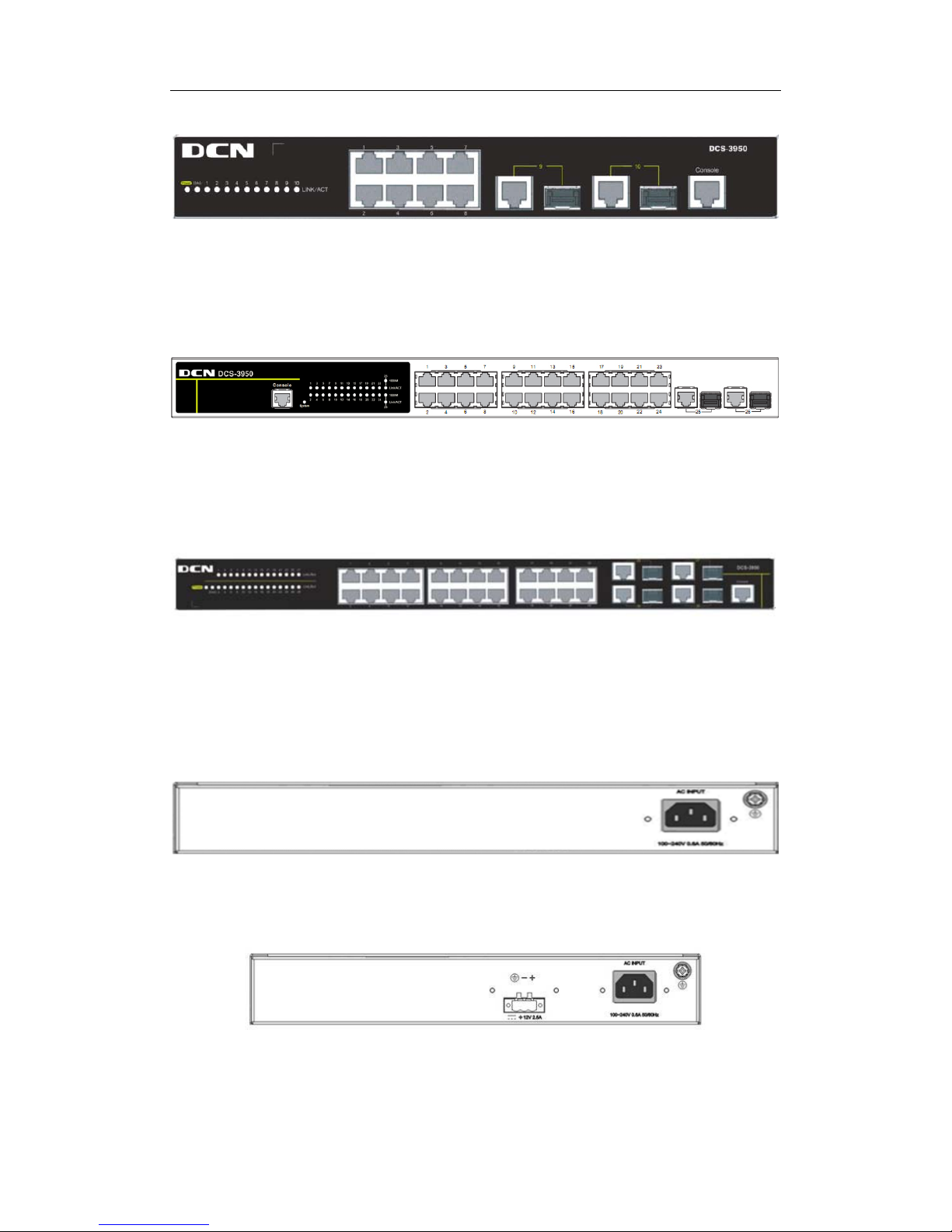
DCS-3950-10C series provide 8 10/100Base-T ports, 2 Combo port s ( 2 RJ-45 and 2
SFP ports), 1 Console port and 12 LEDs.
Page 5
DCS-3950 series Installation manual Chapter 1 Introduction
1-4
The front panel of DCS-3950-10C series is shown as follow:
Fig 1-4 Front Panel of DCS-3950-10C/DCS-3950-10C-R/DCS-3950-10C-DC
DCS-3950-26C provides 24 10/100Base-T ports, 2 Combo ports (2 RJ-45 and 2 SFP
ports), 1 Console port and 29 LEDs.
The front panel of DCS-3950-26C is shown as follow:
Fig 1-5 Front Panel of DCS-3950-26C
DCS-3950-28C series provide 24 10/100Base-T ports, 4 Combo ports (4 RJ-45 and 4
SFP ports), 1 Console port and 30 LEDs.
The front panel of DCS-3950-28C series is shown as follow:
Fig 1-6 Front Panel of DCS-3950-28C/DCS-3950-28C-R/DCS-3950-28C-DC
1.3.2 Back Panel
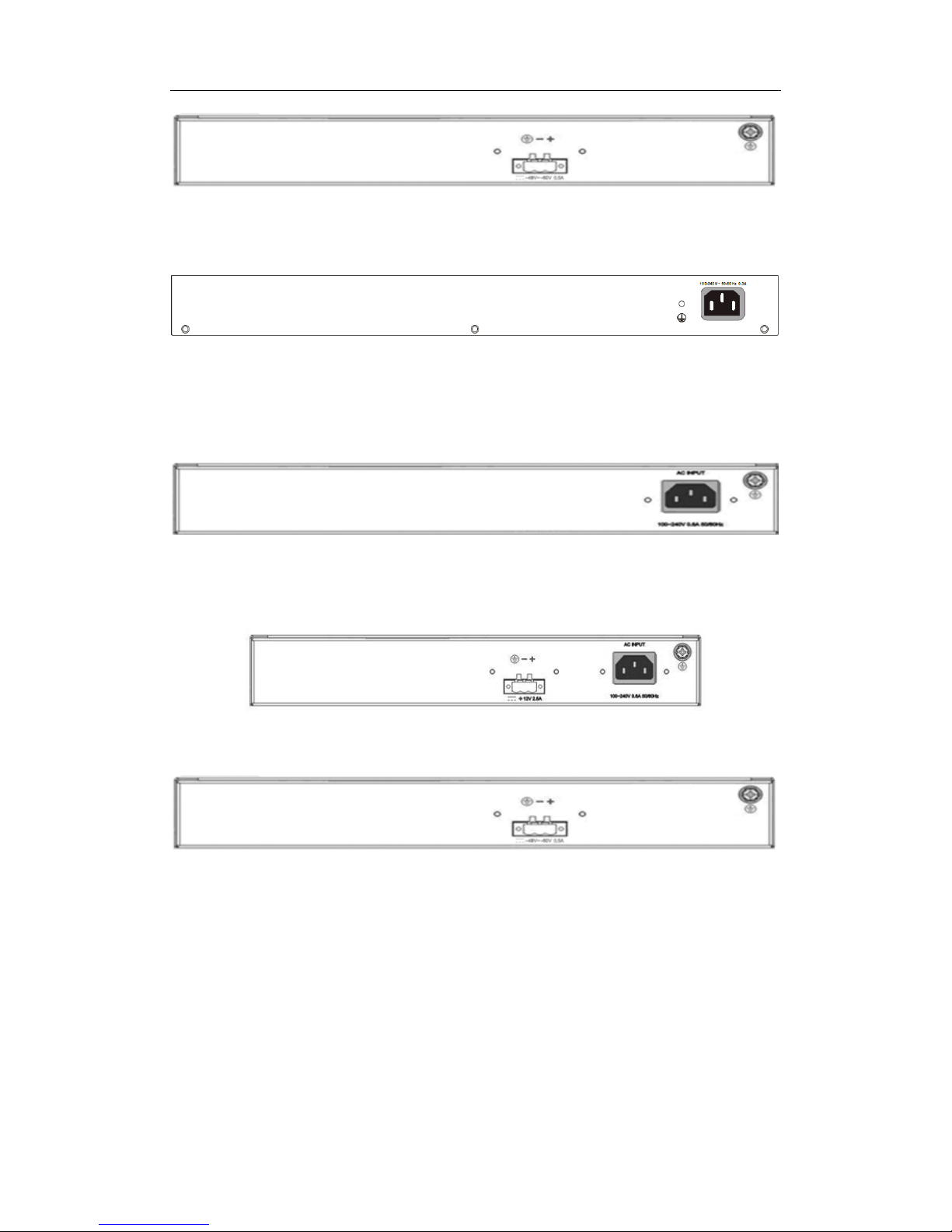
DCS-3950-10C provides a 220V AC power receptacle.
Fig 1-7 Back Panel of DCS-3950-10C
DCS-3950-10C-R provides a 220V AC power receptacle and a 12V DC power
receptacle.
Fig 1-8 Back Panel of DCS-3950-10C-R
DCS-3950-10C-DC provides a -48V DC power receptacle.
Page 6
DCS-3950 series Installation manual Chapter 1 Introduction
1-5
Fig 1-9 Back Panel of DCS-3950-10C-DC
DCS-3950-26C provides a 220V AC power receptacle and a ground connection.
Fig 1-10 Back Panel of DCS-3950-26C
DCS-3950-28C provides a 220V AC power receptacle.
Fig 1-11 Back Panel of DCS-3950-28C
DCS-3950-28C-R provides a 220V AC power receptacle and a 12V DC power
receptacle.
Fig 1-12 Back Panel of DCS-3950-28C-R
DCS-3950-28C-DC provides a -48V DC power receptacle.
Fig 1-13 Back Panel of DCS-3950-28C-DC
1.3.3 Status LEDs
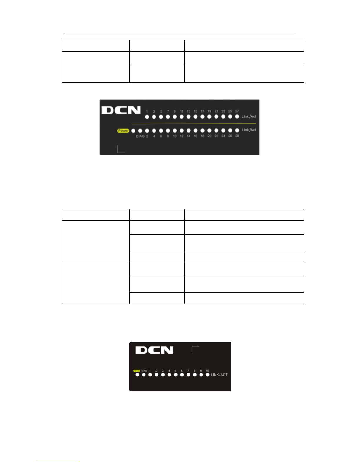
DCS-3950 series switches include port indicator and system status indicator, as
shown in below and described in the following table.
1.3.3.1 Port Indicator Description
Page 7

DCS-3950 series Installation manual Chapter 1 Introduction
1-6
Fig 1-14 DCS-3950-10C series LED diagram
Table 1-1 DCS-3950-10C series port indicator descri ption
Panel Symbol Status Description
Port1-8(Link/Act)
On (Green) The port is linked successfully
Flash(Green)
The p
ort is linked successfully, and
receive/send data
Off The port is not link
Port9/10(Link/Act)
On (Green)
Combo port is linked successfully
Flash(Green)
Combo
port is linked successfully, and
receive/send data
Off Combo port is not link
Fig 1-15 DCS-3950-26C LED diagram
Table 1-2 DCS-3950-26C port indicator description
Panel Symbol Status Description
Port1-24(Link/Act)
On (Green) The port is linked successfully
Flash(Green)
The port is linked successfully, and
receive/send data
Off The port is not link
Port25-26(Link/Act)
On (Green)
The port is linked successfully
Flash(Green)
The port is linked successfully, and
receive/send data
Page 8
DCS-3950 series Installation manual Chapter 1 Introduction
1-7
Off The port is not link
Port25-26 (Speed)
On(yellow)
The port is in the link state of 1000Mbps
Off
The port is in the link state of 10/100Mbps or
at down status
Fig 1-16 DCS-3950-28C series LED diagram
Table 1-3 DCS-3950-28C series port indicator descri ption
Panel Symbol Status Description
Port1-24(Link/Act)
On (Green) The port is linked successfully
Flash(Green)
The port is linked successfully, and
receive/send data
Off The port is not link
Port25/26/27/28(Link/A
ct)
On (Green)
Combo port is linked successfully
Flash(Green)
Combo
port is linked successfully, and
receive/send data
Off Combo port is not link
1.3.3.2 System Status Indicator Description
Fig 1-17 DCS-3950-10C series system LED diagram
Page 9

DCS-3950 series Installation manual Chapter 1 Introduction
1-8
Fig 1-18 DCS-3950-28C series system LED diagram
Table 1-4 system indi cator description
LED Status Description
Power
On (Green) The internal power is operating normally
Off Power is off or error
DIAG
Flash(Green, 1Hz) Operating state is normal
Flash(Green, 8Hz) System is loading
1.3.4 Front Panel Port Description
Each port description is shown below:
Table 1-5 port descrip tion
Interface mode Spec
RJ-45 port
• 10/100Mbps auto negotiation
• MDI/MDI-X cable mode auto negotiation
• 5 kinds of UTP: 100 m
•
Combo port supports 10/100/1000Mbps auto
negotiation
SFP
• SFP-SX-L transceiver
1000Base-SX SF P( 850n m , MMF, 550m)
• SFP-LX-L transceiver
1000Base-LX SFP(1310 nm, SMF , 10 km o r MMF ,
550m)
• SFP-LX-20-L transceiver
1310nm lightwave, 9/125um single mode fiber:
20km
• SFP-LX-40 transceiver
9/125um single mode fiber: 40km
• SFP-LH-70-L transceiver
9/125um single mode fiber: 70km
Page 10

DCS-3950 series Installation manual Chapter 1 Introduction
1-9
• SFP-LH-120-L transceiver
9/125um single mode fiber: 120km
SFP-GT
SFP-GT
1000Base-T SFP interface card module, RJ-45
interface
SFP-FX
SFP-FX
100Base-FX SFP
interface card module
(1310nm, MMF, 2KM), LC interface
SFP-FL
100Base-FL SFP
interface card module
(1310nm, SMF, 15KM), LC interface
SFP-FL-40
100Base-FL SFP
interface card module
(1310nm, SMF, 40KM), LC interface
SFP-FL-80
100Base-FL SFP
interface card module
(1550nm, SMF, 80KM), LC interface
Page 11

DCS-3950 series Installation manual Chapter 2 Hardware Installation
2-1
Chapter 2 Hardware Installation
2.1 Installation Notice
To ensure the proper operation of DCS-3950 series and your physical security,
please read carefully the following installation guide.
2.1.1 Environmental Requirements
The switch must be installed in a clean area. Otherwise, the switch may be damaged
by electrostatic adherence.
Maintain the temperature and the humidity within the set environment.
The s witc h m ust be pu t in a dry and cool pl ac e. Lea ve s uffici ent s paci ng ar ou nd the
switc h for good air c irc ulation. The swi tch shoul d be cushioned on desktop or other
switch.
The switch must work in the right range of power input.
The switc h mus t be well grounded in or der to avoid ESD dam age and ph ysic al i nj ury
of people.
The s witch s hould a void the sunl i ght perpendi cul ar inc i dence. Keep th e s wi tch away
from heat sources and strong electromagnetic interference sources.
The switch must be mounted to a standard 19’’ rack or placed on a clean level
desktop.
2.1.1.1 Dust and Particles
Dust is harmful to the safe operation of DCS-3950. Dust can lead to electrostatic
adherence, especially likel y u nder low relati ve humidity, caus ing poor conta ct of metal
connectors or contacts. Electrostatic adherence will result in not only reduced product
lifes pan, but also i ncreased c hance of com munic ation fail ures. The r ecommended val ue
for dust content and particle diameter in the site is shown below:
Max Diameter (µm)
0.5 1 3
5
Max Density
(particles/m³)
1.4×10⁵ 7×10⁵ 2.4×10⁵ 1.3×10⁵
Table 2-1 Environmental Requirements: Dust content
In addition, salt, acid and sulfide in the air are also harmful to the switch. Such
Page 12

DCS-3950 series Installation manual Chapter 2 Hardware Installation
2-2
harmful gases will aggravate metal corrosion and the aging of some parts. The site should
avoid harm ful gas es, suc h as SO
2
, H2S, NO2, NH3 and Cl2, etc. T he table bel ow detail s
the threshold value.
Gas
Average (mg/m³)
Max (mg/m³)
SO2
0.2
1.5
H2S
0.006
0.03
NO2
0.04
0.15
NH3
0.05
0.15
Cl2
0.01
0.3
Table 2-2 Environmental Requirements: Particles
2.1.1.2 Temperature and Humidity
The switch installation site should maintain a desirable temperature and humidity.
High-humidity conditions can cause electrical resistance degradation or even electric
leakage, degradation of mechanical properties and corrosion of internal components.
Extreme low r elative humidity ma y caus e the insulation spac er to contract, maki ng the
fastening screw insecure. Furthermore, in dry env ironments, static electricity is liable to be
produced and caus e harm to i nternal circ uits. Temperature extremes c an cause reduced
reliabil ity and prem at ure a gi ng of ins ul ati on mat eri als , thus reduc i ng the swi tc h’s wor king
lifes pan. In the hot summ er, it is rec ommended to use air -conditioners to cool down th e
site. And the cold winter, it is recommenced to use heaters. The recommended
temperature and humidity are shown below:
Temperature:
Relative humidi ty
Long term
condition
Short term
condition
Long term
condition
Short term
condition
15~30℃
0~50℃
40~65%
5% ~95%
Table 2-3 Environmental Requirements: Temperat ure and Humidity
Caution!
A sampl e of ambient tem perature and humidi ty should be ta ken at 1.5m abo ve the
floor and 0.4m in front of the switch r ack, with no protecti ve panel covering the front and
rear of the rack. Short term working conditions refer to a maximum of 48 hours of
continued operation and an annual cumulative total of less than 15 days. Formidable
operation condi tions refers to the am bient temperature and rel ative humidi ty value that
may occur during an air-conditioning system failure, and normal operation conditions
should be recovered within 5 hours.
Page 13

DCS-3950 series Installation manual Chapter 2 Hardware Installation
2-3
2.1.1.3 Power Supply
It is adopted modul e switc h power for the s witch, the input par ameters of power are
shown below:
The AC input voltage: 100~240VAC
The frequency: DCS-3950-26C: 47Hz ~ 63Hz
DCS-3950-10C series: 50Hz ~ 60Hz
DCS-3950-28C series: 50Hz ~ 60Hz
The DC input voltage: DCS-3950-10C-R/DCS-3950-28C-R: 12V/2.5A
DCS-3950-10C-DC/DCS-3950-28C-DC: -40V ~ -48V/0.5A
Before powering on the power supply, please check the input power to ensure proper
grounding o f th e p ower s upply system. T he i nput power for t he s wit ch s hould be reliabl e
and secure; a voltage adaptor can be used i f necess ary. T he buil ding’s cir cuit protection
system should include in the circuit a fuse or circuit-breaker of no greater than 240 V, 10 A.
It is recommended to use a UPS for more reliable power supplying. .
Caution!
Improper pow er supply system groun ding, extreme fl uctuation of the input s ource,
and transients (or spikes) can result in larger error rate, or even hardware damage!
2.1.1.4 Preventing Electrostatic Discharge Damage
Static electric can cause damage to inter nal circuits, even the e ntire switc h. Follow
these guidelines for avoiding ESD damage:
Ensure proper ear th groundi ng of the device;
Perform regular cleaning to reduce dust;
Maintain proper temperature and humidity;
Always wear an ESD wri st strap and an tistatic uni form when in contac t with ci rcuit
boards.
2.1.1.5 Anti-interference
All sources of interference, whether from the device/system itself or the outside
environment, will affect operations in various ways, such as capacitive coupling, inductive
coupling, electromagnetic radiation, common impedance (including the grounding sy stem)
and cables/l ines (power cables, si gnal lines, and output lines) . The foll owing should be
noted:
Precautions should be taken to prevent power source interruptions;
Provide the s yst em with a dedic ated grounding, rather than shar ing the groundi ng
Page 14

DCS-3950 series Installation manual Chapter 2 Hardware Installation
2-4
with the electronic equipment or lightning protection devices.
Keep away from high power radio transmitters, radar transmitters, and high frequency
strong circuit devices.
Provide electromagnetic shielding if necessary.
2.1.1.6 Rack Configuration
The dimension of the switch is designed to be mounted on a standard 19’’ rack.
Please ensure good ventilation for the rack.
Every device in t h e rac k wil l gener ate he at dur ing o per ation, th erefor e vent an d fans
must be provided for an enclosed rack, and devices should not be stacked closely.
When m ounting devices i n an open rack, care shoul d be taken to preven t the rack
frame from obstructing the switch ventilation openings. Be sure to check the
positioning of the switch after installation to avoid the aforementioned.
Caution!
If a standar d 19’’ r ack is not a vailable, the switch can be placed on a c lean level
desktop, l ea ve a clear anc e of 1 00mm ar ound th e s wit ch for ventil ati on, and d o not plac e
anything on top of the switch.
2.1.2 Installation Notice
Read through the installation instruction carefully before operating on the system.
Make sure the installation materials and tools are prepared. And make sure the
installation site is well prepared.
During the installation, users must use the brackets and screws provided in the
access ory ki t. Users should us e the proper tools to perform the installation. User s
should always wear antistatic uniform and ESD wrist straps. Users should use
standard cables and connecters.
After the installation, users should clean the site. Before powering on the s witch,
users s hould ensure the swi tch is well grounded. Us ers should mai ntain the switch
regularly to extend the lifespan of the switch.
2.1.3 Se curity Wa rnings
When using SFP transceiver, do not stare directly at the fiber bore when the switch is
in operation. Otherwise the laser may hurt your eyes.
Do not attempt to conduc t the oper ations whi c h can damage the s wi tch or which can
Page 15

DCS-3950 series Installation manual Chapter 2 Hardware Installation
2-5
cause physical injury.
Do not ins tall, move or dis close the switc h and its modul es when the switc h is in
operation.
Do not open the switch shell.
Do not drop metals into the switch. It can cause short-circuit.
Do not touch the power plug and power socket.
Do not place the tinder near the switch.
Do not configure the switch alone in a dangerous situation.
Use standard power sockets which have overload and leakage protection.
Inspect and maintain the site and the switch regularly.
Have the emergence pow er swi tch on the si te. In case of emer gence, switch off the
power immediately .
Caution!
Potential ri sk include: Electric leakage, P ower supply arcing, Power line breakage,
Imperfect earth, Overload circuit and Electrical short circuit..If electric shock, fire, electrical
short circuit occurs, pleas e cut off the electr icity supply and al arm rapidly. Rescue the
injured per son in the c ontingenc y under inherentl y safe, give t he injured person proper
first aid treatment according to the injury state, and seek help from the Medical
Emergency using various ways.
2.2 Installation Preparation
2.2.1 Verify the Package Contents
First, open the package, please check the contents of the switch container and
accessory kit. (If you are concerned that any item is missing or an incorrect item has been
supplied, please contact your dealer as soon as possible.)
2.2.2 Required Tools and Materials
The required tools and utilities are shown below:
Cross screwdrivers
Flat-blade screwdriver
ESD wrist strap
Antistatic uniform
Page 16
DCS-3950 series Installation manual Chapter 2 Hardware Installation
2-6
Caution!
Users should prepare the required tools by themselves.
2.3 Installation Guide
2.3.1 Installing the Switch
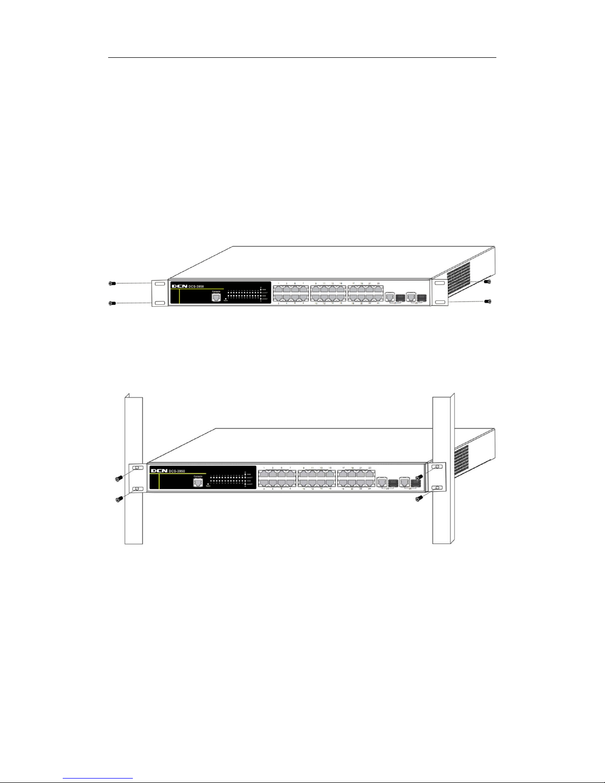
Please mount the switch as below:
1. Attach the 2 brackets on the switch with screws provided in the accessory kit.
Fig 2-1 Fasten the Brackets to the Switch
2. Put the bracket-mounted switch smoothly into a standard 19’’ rack. Fasten the
switch to the rack wi th the screws provided. Leave enough spac e around the swi tch for
good air circulation.
Fig 2-2 Fasten the Switch to the Rack
Caution!
The brac kets are used t o fi x the s witch on t he rack. The y can’t ser ve as a be aring.
Please place a rack shelf under the switch. Do not place anything on top of the switch. Do
not block the blowholes on the switch to ensure the proper operation of the switch.
2.3.2 Switch grounding
Page 17

DCS-3950 series Installation manual Chapter 2 Hardware Installation
2-7
A good grounding system is the groundwork for the smooth and safe operation of the
DCS-3950 series, and an excellent way to prevent lightning strikes and resistance
interference. Please follow the switch grounding specification instructions, verify the
installation site’s grounding condition and ensure proper grounding accordingly.
Proper grounding
When us ing an AC power s ource, the device m ust be ground ed with th e gree n and
yellow ground cables; otherwi se, shock ha zards m ay occ ur when insulation resistance
between the internal power supply and the chassis degrades.
Lightning protec tion grounding
The lightning protection sy stem is an independent system consisting of a lightning rod,
conductor and c onnect ion j oi nt wi th the groundi ng system . T he gr ounding s ystem us uall y
is shared with the power reference grounding and green and yellow ground cable
grounding. Lightning protection grounding is a building requirement, not a specific
requirement of the switch.
Electromagnetic c ompliance grounding
This refers to the grounding to comply with switch electromagnetic compatibility
requirements, including shielded grounding, filter grounds, noise, and interference control
and level referenc e. T he o verall grounding r equir ements are the sum total of the abo ve.
Ground resistance value should be less than 1 ohm.
The DCS-3950 series provides chassis grounding post in the lower rear chassis,
marked as “
”. Chassis protec ti on groundi ng shoul d be pr operl y connected to th e rac k
grounding connector.
The ground cabling procedures are listed below:
Step 1: remove the nuts from the rear chassis grounding posts
Step 2: wrap one end of the green and yellow grounding cable to the grounding posts
Step 3: attach the grounding post nut and tighten well
Step 4: attach the other end of the grounding cable to the rack grounding connector
Note:
The groundi ng cable shoul d be made of a good conduc tor, and the diameter should
be determined by the possible maximum current that may pass through.
Bare conductor cabling is forbidden.
Ground res istanc e value: the c ombined gr oundi ng resis tance shoul d be less than 1
ohm.
2.3.3 Connecting Console
DCS-3950 series provide a RJ45 serial console port.
Page 18

DCS-3950 series Installation manual Chapter 2 Hardware Installation
2-8
Fig 2-3 Connecting Console to switch
The connection procedure is listed below:
1. Find the console cable provided in the accessory kit. Attach the RJ45 end to console
port of the switch.
2. Connect the other side of the console cable to a character terminal (PC).
3. Power on the switch and the c haracter termi nal. Configure the sw itch through the
character terminal.
2.3.4 SFP Transceiver Installation
DCS-3950 series provide multiple 1000Mb SFP transceiver slots.
The procedure for installing the SFP transceiver is shown below:
Step 1: Put on a ESD wrist strap (or antistatic gloves)
Step 2: Insert the SFP transceiver to the guide rail inside the fiber interface line card.
Do not put the SFP transceiver up-side-down.
Step 3: Push the SFP transceiver along the guide rail gently until you feel the
transceiver snap into place at the bottom of the line card.
Note: The SFP transceiver is hot swappable.
Caution!
Do not stare di rectly at the 2 fiber bor e in the SFP transcei ver when the swi tch is in
operation, otherwise the laser may hurt your eyes.
2.3.5 Copper Cable/Fiber Cable Connection
Copper cables should be connected as below:
Page 19

DCS-3950 series Installation manual Chapter 2 Hardware Installation
2-9
Step 1: Insert one end of t he Ethernet cable to the RJ-45 Ethernet port i n the switch
copper cable line card;
Step 2: Insert the other end of the Ethernet cable to the RJ-45 Ethernet po rt of other
device;
Step 3: Ch eck all status i ndicator s for the cor respondi ng ports; a lighted LE D indi cates
that the link has been established, otherwise the link is not ready and the cable should be
examined.
Caution!
Please verif y the sign ab ove the port to ensure using the r ight port. Conn ecting to
wrong ports might damage the switch.
Fiber cables should be connected as below:
Step 1: Remove the pr otecti ve plug f rom the SFP/XF P fiber tr anscei ver bore; R emo ve
the protective cap from one end of the fiber cable. Keep the fiber end clean and neat.
Step 2: Attach one end of the fiber cable to the SFP/XFP transc eiver, and attach the
other end to the transceiver of the corresponding devices. Note: The SFP/XFP
transceiv er’s TX port should be connected to the RX port of the corresponding device, and
vice versa.
Step 3: Check the fi ber port status indicator, a lighted LED indic ates that the link has
been established; otherwise the link is not ready and should be examined.
Caution!
Please verify the sign abo ve the port to ensur e using the other ports. Connec ting to
wrong ports might damage the transceiver or the other ports. When connecting other
devices thr ough a fiber cable to the swi tch, the outp ut power of th e fiber cable m ust not
exceed the maximum received power of the corresponding modules. Otherwise, it will
damage the fiber transceiver. Do not stare at the fiber bore when the switch is in operation.
That may hurt your eyes.
2.3.6 AC Power Supply Connection
DCS-3950 series use the power is 220VAC. Please read the power input
specification for the detailed information.
AC Power supply connection procedure is described as below:
1. Insert one end of the power cable pro vided in the acc essory kit into the power source
socket (wi th overload and leakage protec tion), an d the other end t o the powe r soc ket in
the back panel of the switch.
Page 20

DCS-3950 series Installation manual Chapter 2 Hardware Installation
2-10
2. Check the p ower status i ndicator in the fr ont panel of the s witch. T he corresponding
power indicator should light. Switch is self-adjustable for the input voltage. As soon as the
input voltage is in the range printed on the switch surface, the switch can operate
correctly.
3. When the switch is powered on, it executes self-test procedure and startups.
Caution!
The i nput voltage mus t be within the required range, ot herwise the switc h can be
damaged or m alfunction. Do not open the s witch shel l without permis sion. It can cause
physical injury.
2.3.7 DC Power Supply Connection
Please read the specification for the detailed information. DC Power supply
connection procedure is described as below:
1. Insert one end of the power cable to the power source socket (with overload and
leakage protecti on), and the other end to the DC power s ocket in the back panel of the
switch.
2. Check the power status indicator in the front panel of the switch.
3. When the switch is powered on, it executes self-test procedure and startups.
Caution!
The input voltage must be within the required range, otherwise the switch can be
damaged or m al function. And pay atten ti on to t he p ower polarity. Do not open the s wi tch
shell without permission. It can cause physical injury.
 Loading...