

Page 1

Mark III Directional Drilling
Locating System
Operator’s Manual
DCI Headquarters
nd
19625 62
Kent, Washington 98032 USA
Tel 425 251 0559
Fax 253 395 2800
E-mail DCI@digital-control.com
www.digitrak.com
Ave. S., Suite B-103
/ 800 288 3610
DCI Europe
Kurmainzer Strasse 56
D-97836 Bischbrunn
Germany
Tel +49(0) 9394 990 990
Fax +49(0) 9394 990 999
DCI.Europe@digital-control.com
DIGITAL
C
ONTROL
I
NCORPORATED
DCI India
SCO # 259, Sector 44-C
Chandigarh (UT) 160 047
Punjab, India
Tel +91(0) 172 464 0444
Fax +91(0) 172 464 0999
DCI.India@digital-control.com
DCI China
USA Excalibre
2803 Bldg C, 70 Cao Bao Rd
Shanghai P.R.C. 200233
Tel +86(0) 21 6432 5186
Fax +86(0) 21 6432 5187
DCI.China@digital-control.com
DCI Australia
2/9 Frinton Street
Southport, Queensland 4215
Australia
Tel +61(0) 7 5531 4283
Fax +61(0) 7 5531 2617
DCI.Australia@digital-control.com
Page 2

DIGITAL CONTROL INCORPORATED
3-3000-00-F
© 1999-2006 by Digital Control Incorporated. All rights reserved. July 2006 Edition.
Trademarks
®
The DCI logo, CableLink®, DataLog®, DigiTrak®, Eclipse®, iGPS®, Intuitive®, look-ahead®, SST®, target-in-
the-box
LT™, TeleLock™, and TensiTrak™ are trademarks of Digital Control Incorporated.
®
, and Target Steering® are U.S. registered trademarks and DucTrak™, FasTrak™, SuperCell™,
Patents
The DigiTrak® Locating System is covered by one or more of the following U.S. Patents: 5,155,442;
5,337,002; 5,444,382; 5,633,589; 5,698,981; 5,726,359; 5,764,062; 5,767,678; 5,878,824; 5,926,025;
5,933,008; 5,990,682; 6,002,258; 6,008,651; 6,014,026; 6,035,951; 6,057,687; 6,066,955; 6,160,401;
6,232,780; 6,396,275; 6,400,159; 6,525,538; 6,559,646; 6,593,745; 6,677,768; 6,693,429; 6,756,783;
6,756,784; 6,838,882; 6,924,645; 6,954,073; 7,015,697; 7,049,820; 7,061,244. Sale of a DigiTrak
Receiver does not convey a license under any patents covering the DigiTrak
drill housing. Other patents pending.
®
Transmitter or underground
®
Important Notice
All statements, technical information, and recommendations related to the products of Digital Control
Incorporated (DCI) are based on information believed to be reliable, but the accuracy or completeness
thereof is not warranted. Before utilizing any DCI product, the user should determine the suitability of the
product for its intended use. All statements herein refer to DCI products as delivered by DCI and do not
apply to any user customizations not authorized by DCI nor to any third-party products. Nothing herein
shall constitute any warranty by DCI nor will anything herein be deemed to modify the terms of DCI’s
existing limited warranty applicable to all DCI products.
FCC Compliance Statement
This equipment has been tested and found to comply with the limits for a Class B digital device, pursuant
to Part 15 of the Rules of the Federal Communications Commission. These limits are designed to provide
reasonable protection against harmful interference in a residential installation. This equipment generates,
uses, and can radiate radio frequency energy and, if not installed and used in accordance with the
instructions, may cause harmful interference to radio communications. However, there is no guarantee
that interference will not occur in a particular installation. If this equipment does cause harmful interference to radio or television reception, which can be determined by turning the equipment off and on, the
user is encouraged to try to correct the interference by one or more of the following measures:
Reorient or relocate the DigiTrak Receiver.
¾
Increase the separation between the problematic equipment and the DigiTrak Receiver.
¾
Connect the equipment into an outlet on a different circuit.
¾
Consult the dealer for help.
¾
Changes or modifications to the DCI equipment not expressly approved and carri
the user’s limited warranty and the FCC’s authorization to operate the equipment.
ii DigiTrak® Mark III Operator’s Manual
ed out by DCI will void
Page 3

®
DIGITAL CONTROL INCORPORATED
Table of Contents
SAFETY PRECAUTIONS AND WARNINGS..................................................................................vi
INTRODUCTION..............................................................................................................................
Basic DigiTrak Equipment
Basic DigiTrak Operation
Technical Support
RECEIVER .......................................................................................................................................
Display Window Ic
On/Off..................................................................................................................................
Receiving the Transmitter’
Clicking vs. Holding the T
Changing the Receiver’s Channel Setting
Changing the Depth Measurement Units (English vs.
Battery Status Display for Rec
Warning Tones for Transmitter Overheat
Ultrasonic Func
Setting the Ultrasonic Distance or Height-Above-Ground Measurement
Zeroing the Ultras
Calibrating the Rec
1-Point Calibration Procedure
2-Point Calibration Proc
Calibrating with Transmitter Underground at Shallow Depth
Using Depth Antenna Plumb Line to M
Finding Firmware Vers
5.0 Series Firmware Func
Predicted Depth Key Points
Procedure for Observing the Predic
Viewing the Transmitter’s Temperature and the Rec
Viewing the Receiver’s B
Off Feature
Accessing the Receiver’s Running Time Meter
TRANSMITTER..............................................................................................................................
How a Transmitter Works
Batteries.............................................................................................................................
Temperature Display
Battery Status Dis
Temperature Overheat
Sleep Mode (Automatic Shutoff)........................................................................................
Verifying Proper Fit of Trans
Locating the Trans
Sensitive-Pitch Trans
Transmitter as an Inc
Serial Numbers
Specifications.....................................................................................................................
................................................................................................................3
ons .........................................................................................................6
tion............................................................................................................11
eiver....................................................................................................13
..................................................................................................................18
play.......................................................................................................20
mitter....................................................................................................23
..................................................................................................................24
...................................................................................................1
.....................................................................................................2
s Signals....................................................................................8
rigger ..........................................................................................8
...........................................................................9
Metric) ..........................................10
eiver and Transmitter ........................................................10
..........................................................................11
....................12
onics................................................................................................12
.....................................................................................13
edure.....................................................................................14
(<10 ft).........................16
ark Locate Points ................................................16
ion..................................................................................................17
tions..........................................................................................17
........................................................................................17
ted Depth............................................................18
eiver’s Battery Status ..............18
attery Voltage......................................................................18
..........................................................18
..................................................................................................19
.........................................................................................................20
......................................................................................................20
mitter in Housing ..................................................................21
mitters..............................................................................................23
linometer..........................................................................................23
1
5
7
19
20
21
24
DigiTrak® Mark III Operator’s Manual iii
Page 4

IGITAL CONTROL INCORPORATED
D
Table of Contents (Cont.)
REMOTE DISPLAY SYSTEM........................................................................................................25
On/Off and Setting the Channel
Transmitter Temperature and Battery
Remote Steering
Finding Firmware Vers
DataLog Capability............................................................................................................28
BATTERY CHARGE
Charging a Battery
Conditioning a Battery in t
Conditioning a Battery Manually........................................................................................
Indicator Lights and Meani
SYSTEM OPERATING INSTRUCTIONS
Start-up Procedure
Shutdown Procedure
Moisture and Temperature Avoidance
Optimal Operating Temperatures
General Maintenance........................................................................................................
SIGNAL INTERFERE
Electrical Interference/Back
Suggestions for Dealing with Interference
OPERATIONAL TESTS
Self-Test for Mark III Rec
Receiver Balance Check
Receiver Gain Test............................................................................................................38
Transmitter Tes
Transmitter Salt Water Range Tes
Transmitter Battery Tests..................................................................................................41
LOCATING
.....................................................................................................................................43
Locate Points (FNLP & RNLP) and Locate Line (PLL)
Handling the Rec
Distance Between FNLP and RNLP Due to Depth, Pitch, and Topography
Using Plus/Minus Indicators
Locating the Transmitter from the Drill..............................................................................
Finding the Rear Negative Locate Point (RNLP)
Finding the Positive Loc
Finding the Front Negative Loc
Finding the Transmitter and Its
Locating the Transmitter from the Front
Method for Confirming Position
Locating on the Fly............................................................................................................50
Off-Track Locating
Splitting the Front and Rear Negative Locate Points
Four Turn Tec
................................................................................................................27
ion..................................................................................................28
R....................................................................................................................29
.............................................................................................................30
............................................................................................................33
.........................................................................................................33
NCE .............................................................................................................35
.................................................................................................................37
eivers.........................................................................................37
...................................................................................................37
ts...............................................................................................................38
eiver.......................................................................................................44
.............................................................................................................50
hnique.........................................................................................................51
........................................................................................26
Status....................................................................26
he Charger...............................................................................31
ngs...........................................................................................31
......................................................................................33
..............................................................................33
......................................................................................34
ground Noise Check..............................................................35
.........................................................................36
t...................................................................................40
.....................................................43
.....................44
for Locating..........................................................................45
........................................................45
ate Line (PLL).......................................................................46
ate Point (FNLP)........................................................47
Depth.........................................................................48
............................................................................49
.........................................................................................49
........................................................51
®
31
34
45
iv DigiTrak® Mark III Operator’s Manual
Page 5

®
DIGITAL CONTROL INCORPORATED
Table of Contents (Cont.)
LOCATING (Cont.)
Calculating Depth Based on Distance Between FNLP
Running Off Pitch or Calculating Depth from Pitc
Transmitter’s Signal Shape
Antennae Configuration
Signal Reception
Front and Rear Negative Loc
Positive Locate Line Above Transmitter............................................................................55
CABLE TRANSMITTER S
Power Suppl
Cable Transmitter
Remote Display with Cable Transmitter Capability
Viewing the Cable System Battery Sta
Operation...........................................................................................................................
TROUBLESHOOTING ...................................................................................................................
GLOSSARY....................................................................................................................................
APPENDIX......................................................................................................................................
Depth Increase in Inches per 10-foot Rod
Percent of Grade to Degree Conversi
Percent of Grade to Degree Conversions
(0.1% Pitch Transmitters or Sensitive Pitch)...............................................................76
Degree to Percent of Grade Convers
Degree to Percent of Grade Conversions
Calculating Depth Based on Distance Between FNLP
REMOTE TELEMETRY LICENSE
LIMITED WARRANTY
...............................................................................................................54
YSTEM .................................................................................................57
y.....................................................................................................................59
..............................................................................................................60
...............................................................................................54
.....................................................................................................54
ate Points............................................................................55
tus ........................................................................62
.........................................................................74
ons (1% Pitch Transmitters) ..................................75
ions (1% Pitch Transmitters) ..................................77
(0.1% Pitch Transmitters) ...............................78
& RNLP .......................................52
h ...........................................................53
...........................................................61
and RNLP....................................79
62
63
69
73
DigiTrak® Mark III Operator’s Manual v
Page 6

IGITAL CONTROL INCORPORATED
D
Safety Precautions
and Warnings
Important Note: All operators must read and understand the following Safety
Precautions and Warnings before using the DigiTrak Locating System.
1 Serious injury and death can result if underground drilling equipment makes contact
with an underground utility such as a high-voltage electrical cable or a natural gas
line.
) Substantial property damage and liability can result if underground drilling equipment
makes contact with an underground utility such as a telephone, fiber-optic, water, or
sewer line.
®
) Work slowdown and cost overruns can occur if drilling operators do not use the
drilling or locating equipment correctly to obtain proper performance.
¾ Directional drilling operators MUST at all times:
•
Understand the safe and proper operation of drilling and locating equipment, including the
use of groun
Ensure that all underground utilities have been l
•
prior to drilling.
Wear protective safety clothing such as dielectric boots, glo
•
vests and safety glasses.
•
Locate and track the drill head accurat
Comply with state and local governme
•
Follow all other safety procedures.
•
¾ The DigiTrak System cannot be used to locate utilities.
¾ Continued exposure to heat, due to frictional heating of the drill head from drilling in sand, gravel,
or rock without sufficient fluid flow around the Transmitter, can cause inaccurate depth to be
displayed and may permanently damage the Transmitter. For more information see “Temperature Overheat” in the Transmitter Section.
d mats and proper grounding procedures.
ocated, exposed, and marked accurately
ves, hard-hats, high-visibility
ely and correctly during drilling.
ntal regulations (e.g., OSHA).
) The DigiTrak equipment is not explosion-proof and should never be used near
flammable or explosive substances.
vi DigiTrak® Mark III Operator’s Manual
Page 7

®
DIGITAL CONTROL INCORPORATED
Safety Precautions
and Warnings (Continued)
¾ Prior to the start of each drilling run, test the DigiTrak System to confirm that it is operating
properly and check that it is providing accurate drill head location and heading information (see
Receiver Section) and accurate drill head depth, pitch, and roll information with the Transmitter
inside the drill head.
¾ During drilling, the depth will not be accurate unless:
•
The Receiver has been properly calibrated and the calibration has been checked for
accuracy so
The drill head has been located correctly and accurately and the Receiver is directly above
•
and pa
point (FNLP).
that the Receiver shows the correct depth.
rallel to the Transmitter in the tool underground or above the front negative locate
•
The Receiver height-above-ground or ultrasonic distance has been set correctly.
•
The Receiver is kept level.
¾ Interference can cause inaccuracies in the measurement of depth and loss of pitch, roll, or the
Transmitter’s location or heading. The locating operator should perform an electrical interference check prior to drilling (see “Electrical Interference/Background Noise Check” in the Signal
Interference Section).
•
Sources of interference include traffic signal loop
lines, fiber-trace lines, metal structures, cathodic protection, transmission towers, and radio
frequencies.
•
Interference with the operation of the Remote
operating nearby on the same frequency, such as car rental agencies using their remote
check-in modules, other directional drilling locating equipment, etc.
¾ Carefully review this Operator’s Manual and the Di giTrak training video and be sure you always
operate the DigiTrak System properly to obtain accurate depth, pitch, roll, and locate points. If
you have any questions about the operation of the DigiTrak System, please call DCI’s Customer
Service Department at 425-251-0559 or 800-288-3610 betw een the hours of 6:00 a.m. and 6:00
p.m. Pacific Time, Monday through Friday, and we will assist you in any way possible.
s, invisible dog fences, cable TV, power
Display may also occur from other sources
REMEMBER
If you are having difficulty on the job, call DCI (425-251-0559 or
800-288-3610) and we’ll attempt to help you solve the problem.
DigiTrak® Mark III Operator’s Manual vii
Page 8

IGITAL CONTROL INCORPORATED
D
Dear Customer:
We would like to thank you for choosing the DigiTrak Locating System. We are proud of
the equipment that we have been designing and building in Washington State since
1990. We believe strongly in providing a unique, high-quality product and standing
behind it with superior customer service and training.
®
We ask that you take the time to read this entir
e manual—especially the section on
safety. Also, please fill in the warranty registration and mail it in or fax it to us at 253395-2800. We will put you on the Digital Control mailing list and send you product
upgrade information and our monthly newsletter FasTrak™.
We also ask that you feel free to contact us at 425-251-
0559 or 800-288-3610 if you are
experiencing any problems with the equipment or have any questions regarding its use.
Our Customer Service Department is available to provide assistance.
The DigiTrak equipment has evolved considerably
since the first Mark I system in 1990.
Many of the improvements to the equipment have been made in response to our
customer’s needs and suggestions. This manual is written for all versions of the
equipment—from our first units to the most recent Mark III.
As this industry grows, we try to keep an eye
on the future to develop equipment that
will make your job faster and easier. We encourage you to stay current by visiting our
web site on the Internet at www.digitrak.com
or calling us at 425-251-0559 or 800-288-
3610.
We welcome questions, comments, and ideas.
Digital Control Incorporated
Kent, Washington
July 2006
3-3000-00a-F
viii DigiTrak® Mark III Operator’s Manual
Page 9
®
DIGITAL CONTROL INCORPORATED
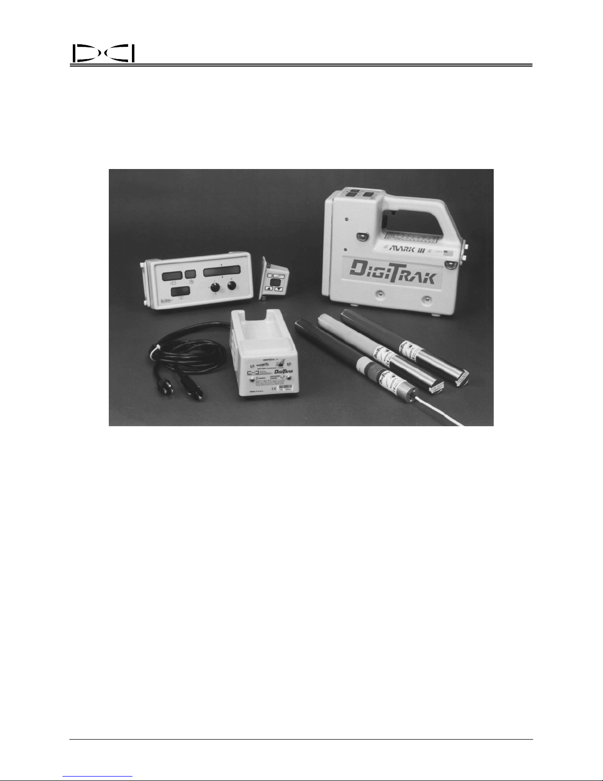
Introduction
Receiver
Remote Display
Batt ery Cha rg e r
DigiTrak
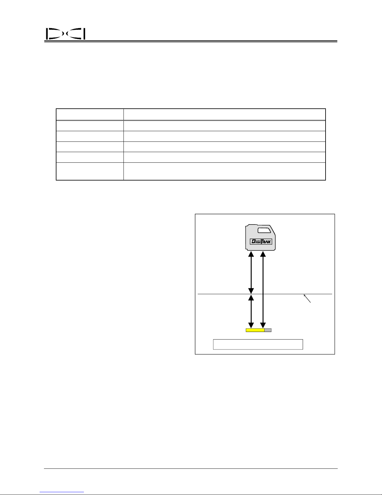
The DigiTrak Locating System is used during horizontal directional drilling operations for locating an
tracking the transmitter within the tool. This manual provides detailed information about the DigiTrak
System and how to use it. The main system components are the Receiver, the Transmitter, the Remote
Display, and the Battery Charger, which are described below. The optional DataLog
used with the DigiTrak equipment to record and map your drilling data. These systems can be upgraded
for use with the Cable Transmitter System, providing locating capability up to 140 ft (42.7 m) from the
transmitter.
DataLog
Module
Cable
Transmitter
®
Directional Drilling Locating System
Transmitters
®
System can be
d
Basic DigiTrak Equipment
Receiver – The DigiTrak Receiver receives signals from the transmitter, processes the signal information,
and displays the transmitter’s status (roll, pitch, depth/distance, predicted depth, battery, and temperature). It may also be equipped to send this information to the remote display at the drill. The most
current model of DigiTrak Receivers is the Mark III. Older versions are the Mark II or Mark I. Only on the
Mark III Receiver is the version identified; older versions are not specified on the receiver. If you need to
know what version you have, you can contact DCI.
Transmitter
tool/housing to send information to the receiver. The receiver displays depth/distance, signal strength,
pitch, roll, battery, and temperature status. Power is supplied using C-cell alkaline batteries, except for
DigiTrak® Mark III Operator’s Manual 1
– Also referred to as a sonde, beacon, or probe, the DigiTrak Transmitter is placed in the drill
Page 10

®
Introduction
the optional cable transmitter, which requires a 12V to 28V DC system. For gravity sewer installations,
DCI manufactures a sensitive-pitch transmitter that measures pitch in 0.1% increments.
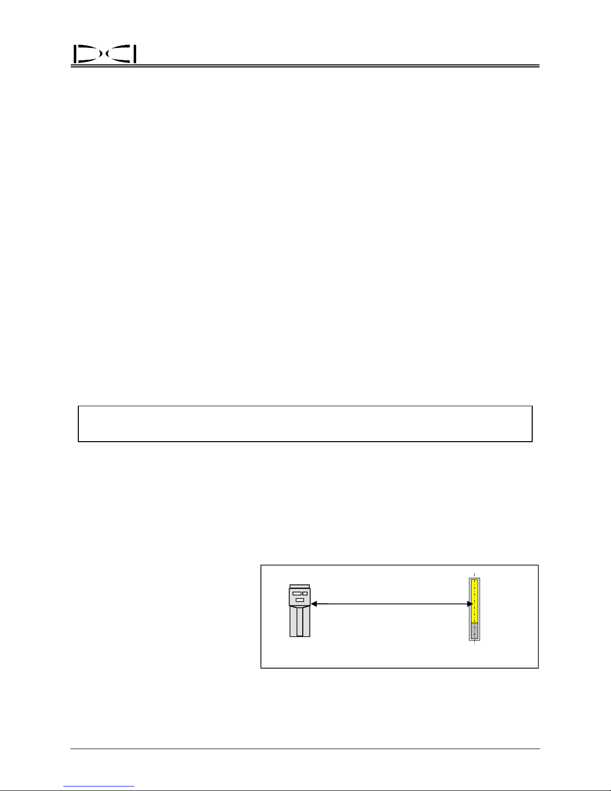
Remote Display – The DigiTra
pitch, roll, depth, predicted depth, and temperature, and can also be used for remote steering when walkover tracking is not possible.
Battery Charger – The DigiTrak Battery Charger is used to charge and condition the DigiTrak NiCad
battery packs. May be used with AC or
DataLog System – The Di
cording and plotting the borepath location.
Cable Transmitter System – The DigiTrak Cable Transmitter System is an optional add-on deep locating
system used for
drill, do not allow walkover locating, and/or are in high-interference areas.
borepaths that are deeper than 50 ft (15 m), have lengths that require several days to
k Remote Display unit enables the drill operator to view the transmitter’s
DC sources and is easily adapted for worldwide usage.
giTrak DataLog System is an optional “as-built” mapping system used for re-
Basic DigiTrak Operation
Safety Precautions and Warnings – All DigiTrak operators must review the safety precautions and
warnings provided at the front of this manual before using the DigiTrak System.
Trigger Click / Hold – T
mediately released in less than ½ second) or held in. These two actions provide different results and are
used in different operating procedures. (see “Clicking vs. Holding the Trigger” in the Receiver Section)
Calibration – The DigiTrak System requires calibration prior to first time use and when any of the
followin
quired every day; however, DCI recommends you verify the calibration by checking the distance readings
(bottom window) with a tape measure prior to the beginning of each drilling run. (see “Calibrating the
Receiver” in the Receiver Section)
g equipment is introduced: transmitter, receiver, or transmitter housing. Calibration is not re-
he trigger under the receiver’s handle can be either clicked (pushed in and im-
Ultrasonic Distance / Height-Above-Ground Measurement – T
ground measurement is the distance between the DigiTrak Receiver and the ground. This distance is
measured by the two ultrasonic transducers on the bottom of the receiver. (see “Ultrasonic Function” in
the Receiver Section)
Depth vs. Distance – When the trigger is not held in, the bottom windo
distance from the receiver to the transmitter, unless the receiver is out of range of the transmitter. Once
the receiver is on and calibrated, it is not necessary to wait for depth readings because the receiver
continuously measures this distance. When the receiver is directly above the transmitter, the information
in the bottom window is referred to as the depth. When the receiver is not directly above the transmitter,
the number in the bottom window is referred to as the “slant” distance. (see “Clicking vs. Holding the
Trigger” in the Receiver Section)
Predicted Depth – If the
only be accurate if the receiver is at the front negative locate point (FNLP). The predicted depth is
displayed in the bottom window as a flashing number with a solid squiggle. (see “Clicking vs. Holding the
Trigger” and “5.0 Series Firmware Functions” in the Receiver Section)
2 DigiTrak® Mark III Operator’s Manual
trigger is held in, the bottom window will display the predicted depth, which will
he ultrasonic distance or height-above-
w of the receiver displays the
Page 11

®
Introduction
Operational Tests – Before drilling and during operation it is necessary to check the following: proper
calibration, correct ultrasonic measurement, status of battery power, transmitter temperature, and signal
interference problems. (see Operational Tests Section)
Locating – The DigiTrak System is used to locate the tran
receiver’s handle is held in during locating to show signal strength in the upper left window. The operator
systematically follows the signals received from the transmitter to establish the FNLP and the rear
negative locate point (RNLP), which then guide the operator to the transmitter’s location. (see Locating
Section)
Tracking
roll) and distance. It is not necessary to push the trigger or take any other steps to see this information.
Troubleshooting –
many different factors. We have listed many of the common problems and solutions in the Troubleshooting Section in this manual. If you cannot find the answers you need there, then please call DCI for
assistance. (see “Technical Support” below)
– The DigiTrak Receiver automatically “tracks” and displays the transmitter’s orientation (pitch/
The DigiTrak System is a sensitive instrument whose operation can be affected by
smitter underground; the trigger under the
Technical Support
If you are having difficulties with your DigiTrak System and cannot find solutions by reviewing this manual
or the DigiTrak Training Video, then call DCI’s Customer Service Department at 425-251-0559 or 800288-3610. When you call, you should be prepared to provide the following information:
Serial numbers on the DigiTrak Receiver, Transmitter, Remote Display, etc.
¾
¾
Description of problem.
¾
How you have tried to solve the problem.
¾
Availability of other equipment to troubleshoot with.
You may also want to visit our web site (www.digitrak.com) for more information, or e-mail us at
DCI@digital-control.com.
DigiTrak® Mark III Operator’s Manual 3
Page 12

Introduction
Notes
®
3-3000-00b-F
4 DigiTrak® Mark III Operator’s Manual
Page 13
®
DIGITAL CONTROL INCORPORATED
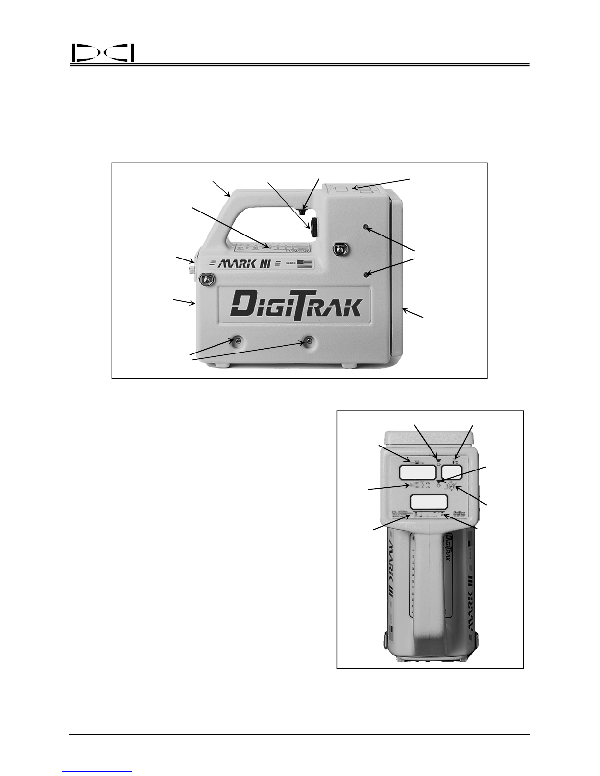
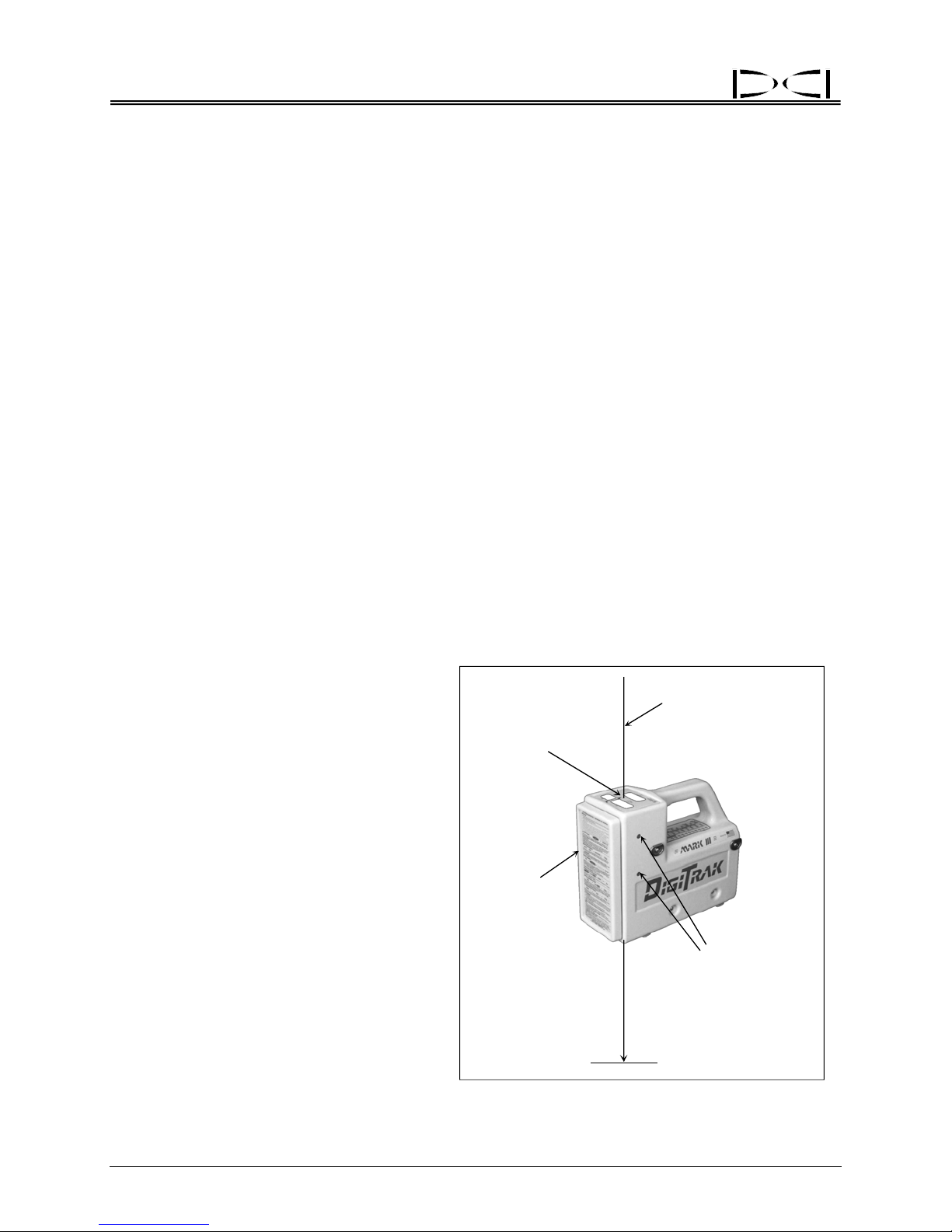
Receiver
Trigger
Temperature
& Distance
Conversion
Chart
Battery
Compartment
Back Panel
Pitch/Roll
Antenna Screws
Handle
Speaker
DigiTrak Receiver – Side View
The DigiTrak Receiver is a hand-held unit used for locating an
d tracking the transmitter. It receives and converts
signals from the transmitter and displays the following
information: pitch, roll, depth/distance, predicted depth,
temperature, and battery status. The display windows
are located on the top of the receiver.
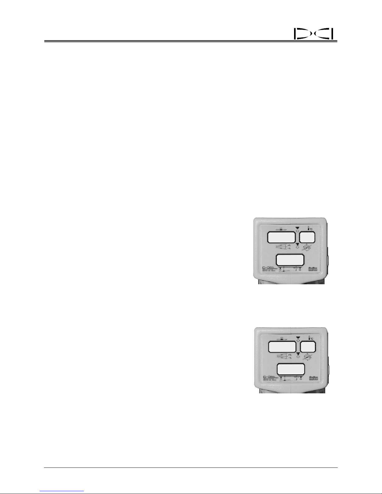
Next to each DigiTrak display window are symbols or
icons to help you identify the functions of each window
(see table on next page). The icons below each window
represent the pitch, roll, and depth/distance of the
transmitter, which are displayed when the trigger is
released, as shown by the trigger down icon. When the
trigger is held in (trigger up), the top left window will
display the signal strength and the top right window will
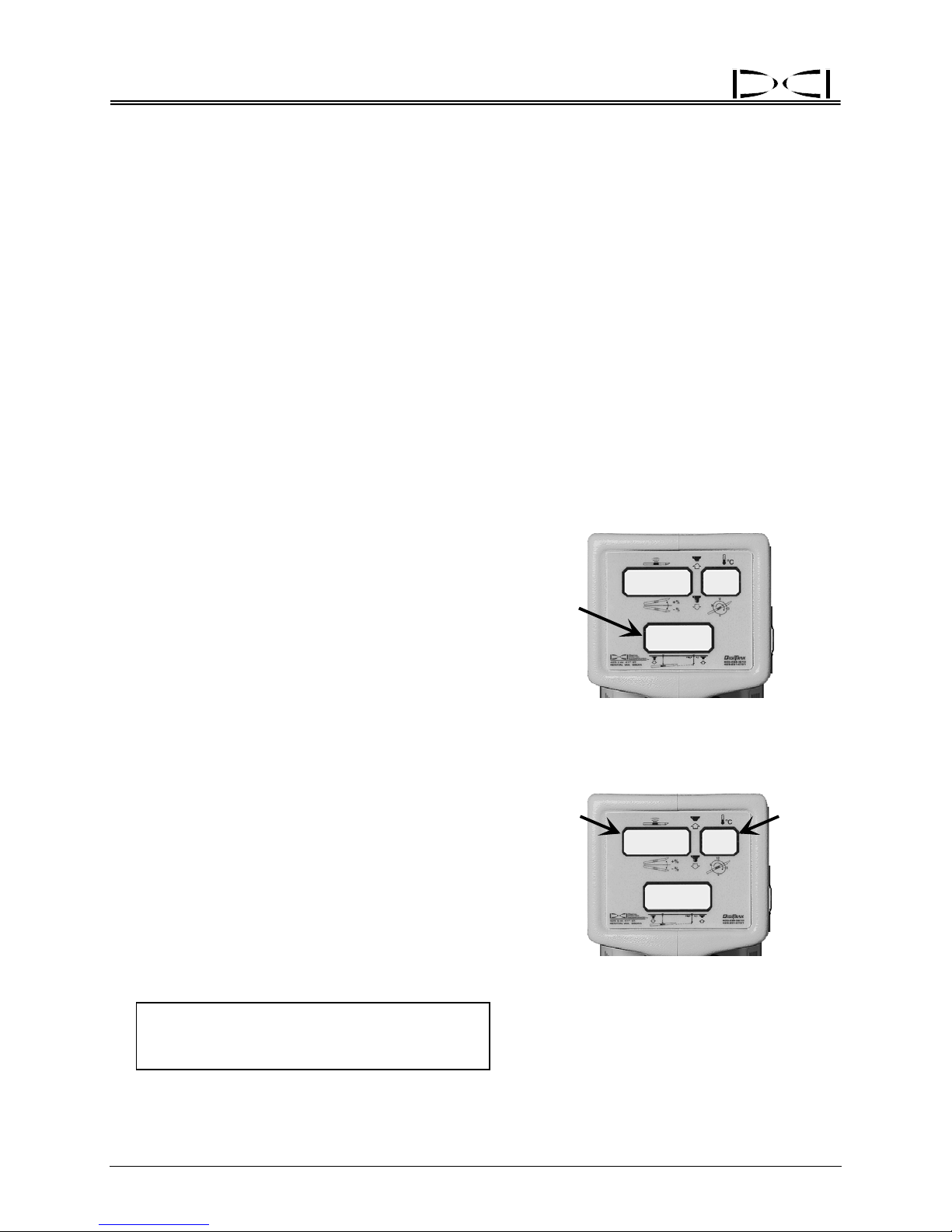
display the temperature. Note the predicted depth icon
below the bottom window. When the trigger is held in
and the receiver is positioned at the front negative locate
point (FNLP), the predicted depth of the transmitter at
the FNLP is displayed in the bottom window. This
predicted depth number will flash quickly and the bottom
window will also show a solidly illuminated squiggle (“~”)
to further set it apart from the depth display.
NOTE:
Should the trigger be held in at any location
other than the FNLP, the predicted depth shown will not
be valid.
Display
Windows
Depth/Locating
Antenna Screws
Front Panel
Trigger Up
Signal
Strength
Pitch
Depth
DigiTrak Receiver
~
I 5
I
I
Temperature
8
8
– Top View
Showing Display Window Icons
Trigger
Down
Roll
Predicted
Depth
DigiTrak® Mark III Operator’s Manual 5
Page 14
Receiver
®
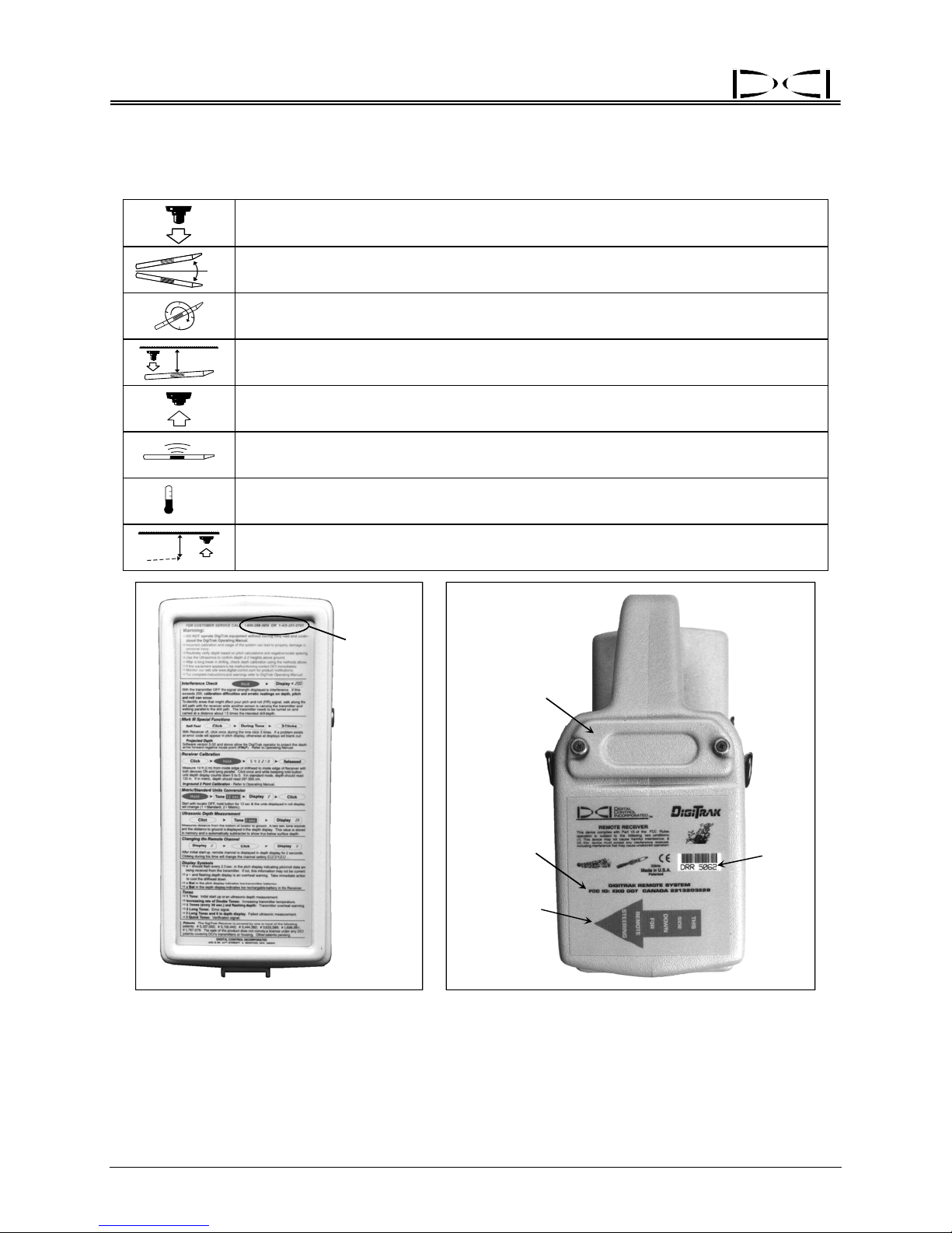
Display Window Icons
Trigger down – Trigg
distance/depth of the transmitter.
+%
Pitch – Numbers from 0% to ±100% show the inclination of the transmitter with
ct to horizontal; 100% represents a 45° angle (top left window, trigger down).
respe
- %
12
9
6
x
o
x
FNLP
3
Roll – Numbers from 1 to 12 show the roll position (1 o’clock to 12 o’clock) of the
transmitter (t
Depth – The
with respect to the surface of the ground when the trigger is down.
Trigger up –
op right window, trigger down).
bottom window displays the depth or slant distance of the transmitter
Trigger is held in; display windows show signal strength, transmitter
temperature, and predicted depth when operator is at FNLP.
Signal strength – Numbe
signal from the transmitter (top left window, trigger up).
Transmitter temperature
C
–
+/
right window, trigger up).
Predicted depth – The b
transmitter at the FNLP when the trigger is up and the receiver is at the FNLP.
800-288-3610
425-251-0559
er is released; display windows show pitch, roll, and
rs from 0 to 999 are displayed to show the strength of the
– Temperature of the transmitter in degrees Celsius (top
ottom window displays the predicted depth of the
Customer
Service
Phone
Numbers:
and
Battery
Compartment
DigiTrak Receiver – Front Panel DigiTrak
Showing Condensed Instructions Showing Identification Information
The front panel of the receiver has condensed instruction
numbers for troubleshooting assistance. There is also a sticker under the handle for temperature and distance conversions. The serial number is located on the back panel of the unit below the battery compartment; it is preceded by the letters DR or DRR (for DigiTrak Receiver and DigiTrak Remote Receiver,
6 DigiTrak® Mark III Operator’s Manual
Orange Arrow
Telemetry
Information
Indicates
Remote
Capability
Serial
Number
Receiver – Back Side
s for quick field reference and DCI’s phone
Page 15
®
Receiver
respectively). If there is an orange arrow below the serial number, then it is a remote receiver, and it is
capable of sending a signal to a remote display unit at the drill. All receivers can be upgraded to remote
capability. The Mark III Receivers (serial numbers greater than 4676) are also equipped with a backlit
display for dim viewing conditions. All receivers can be upgraded to have a backlit display.
DigiTrak equipment is like a computer in that it req
will convey information. Over time, the firmware is changed and upgraded to accommodate new features
and functions in the system. New versions of the firmware are available for upgrading older systems, but
the firmware must be upgraded by DCI. To determine the firmware version installed in your equipment,
see “Finding Firmware Version” in the Receiver and Remote Display Sections.
All Mark III Receivers have the capability of performing a self-test
operating properly. DCI recommends that you complete the self-test every day before locating (see “SelfTest for Mark III Receivers” in the Operational Tests Section).
IMPORTANT: The re
ceiver is designed to be held comfortably in such a manner that it levels itself.
Keeping the receiver level is critical for the most accurate locating.
uires firmware. The firmware determines how a unit
to determine if the unit appears to be
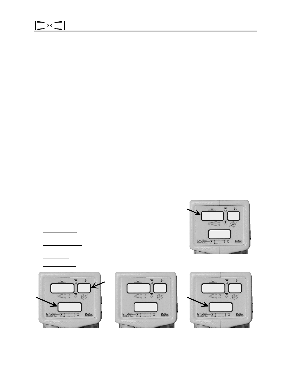
On/Off
To turn the receiver on:
1. Place a fully charged battery pack into the battery compartment, terminal end in first.
2. Click the trigger one time. The unit will sound a tone from the speaker adjacent to the trigger.
3. During the start-up sequence, the three display windows
the order given here:
¾ Top Left Window
shown with no decimal point—e.g., 507 is version 5.07); older
units will display the firmware version only if the trigger is held in
at start-up.
¾ Bottom Window
(155 is 15.5V DC); older units will not display this information.
¾ Top Right Window
(1 = inches, 2 = centimeters).
¾ All Windows
¾ Bottom Window
: Firmware version in the receiver (version is
: Receiver’s battery voltage in tenths of a volt
: English or metric depth measurement units
: LCD test (888’s and all symbols will display).
: Remote channel setting (0 = off, 1,2,3,4 = on).
will quickly flash the following information, in
507
Firmware Version
507
55
I
Depth Measurement Units
and Receiver Battery Voltage LCD Test Remote Channel Setting
DigiTrak® Mark III Operator’s Manual 7
I
BAT
~
+
888
~
–
888
I
BAT
88
2
Page 16
®
Receiver
The depth measurement units (centimeters or inches) and remote channel setting can be changed only
during start-up (see “Changing Depth Measurement Units” and “Changing the Channel Setting” below).
After the start-up process, t
within range (see Tracking Mode display below). If an active transmitter is not within range, 1999 will
appear in the bottom window and the top windows will be blank. If the bottom window is not displaying
1999 and there is no active transmitter within range, an unknown signal is present.
To turn the receiver off:
The receiver will automatically shut itself off if no signal is received for 15 minutes.
To turn off a receiver when a signal is present, click the tri
times. All windows will blank out, signifying that the unit is off.
To turn off a receiver with pre-5.0 series firmware when a
manually.
(For more information on the 5.0 series firmware a
Holding the Trigger” and “5.0 Series Firmware Functions” in this section.)
he windows will display pitch, roll, and distance if there is an active transmitter
gger once and, during the tone, quickly click 4
signal is present, the battery must be removed
nd operating/display differences, see “Clicking vs.
Receiving the Transmitter’s Signals
After charged batteries are loaded into the transmitter (positive end
first), the receiver
top left window, roll (12 positions) in the top right window, and depth
(or distance) in the bottom window. With the DigiTrak System it is not
necessary to push any buttons to receive pitch, roll, or depth/distance;
this information is updated and displayed automatically. The flashing
squiggle (“~”) in the top left window indicates that pitch and roll
updates are being received from the transmitter. For the best results,
wait for two squiggles with the same pitch/roll information before
giving a steering command to confirm the accuracy of the data.
enters “tracking” mode and will display pitch in the
Pitch, Roll, Depth/Distance,
~
I 5
Tracking Mode Showing
and Update Symbol
8
I
8
I
Clicking vs. Holding the Trigger
Clicking the trigger versus holding t
modes with your receiver. When the trigger is held in (trigger up) the
receiver is in the “locating” mode, and the top left window will display
signal strength. Also displayed in the top left window, along with the
signal strength, are the plus (“+”) and minus (“–”) symbols. These
symbols are the key to locating the transmitter (see Locating Section).
The bottom window will display the predicted depth, along with a
flashing squiggle. The top right window will flash the transmitter’s
temperature in degrees Celsius.
8 DigiTrak® Mark III Operator’s Manual
he trigger will initiate different
+
653
~
Locating Mode Showing
Signal Strength,
Transmitter Temperature,
and Predicted Depth
I
22
27
Page 17

®
Receiver
For receivers that have pre-5.0 series firmware, the bottom window will continue to display the receiver’s
distance from the transmitter in the bottom window, not the predicted depth. (For more information, see
“5.0 Series Firmware Functions” in this section or see the Locating Section.)
Any time the trigger is clicked (pu
ultrasonic measurement, which is also referred to as the height-above-ground measurement. This
measurement is the distance between the receiver and the ground, which is measured by the ultrasonic
transducers on the bottom of the receiver. An ultrasonic measurement can be taken an unlimited number
of times (reset) without affecting the receiver’s calibration. The ultrasonic function is independent of the
transmitter and measures the receiver’s elevation above the ground. The ultrasonic distance is
automatically subtracted from the distance to the transmitter to provide the operator with a display of the
transmitter’s depth/distance below the ground’s surface. The ultrasonics were designed to reduce the
effects of interference by increasing the separation between the interference source in the ground (e.g.,
rebar) and the receiver. (For more information, see “Ultrasonic Function” later in this section.)
shed in and released in less than ½ second), the receiver will initiate an
Changing the Receiver’s Channel Setting
If using a remote display unit, the receiver and remote display unit must each be set to the same channel.
Changing the receiver’s channel selection can only be done at start-up.
To change the channel:
At the end of the start-up sequence, the bottom window
1, 2, 3, or 4) for 2 seconds. During this time, the trigger can be clicked to change the channel to the
desired setting. This setting will remain until you change it. Replacing the batteries in any piece of
equipment will not affect the current channel setting, the ultrasonic setting, or the receiver’s calibration.
NOTE: A
signal is being sent to the remote display unit. “Dashes” will appear across the three display windows on
the remote display to indicate no signal is being received. Setting the receiver to channel 0 can be done
to conserve the receiver’s battery (see Remote Display Section).
zero (0) remote channel setting indicates that the receiver’s telemetry signal is shut off and no
will display the current remote channel setting (0,
The DigiTrak System uses ultrahigh-frequency telemetry to com
remote display. Both the receiver and the remote display must have the same type of telemetry to
communicate properly.
DigiTrak® Mark III Operator’s Manual 9
municate between the receiver and the
Page 18
®
Receiver
Changing the Depth Measurement Units (English vs. Metric)
The DigiTrak Receiver is capable of displaying depth in either inches (English) or centimeters (metric).
The depth measurement units can only be changed during the start-up process.
To change the measurement units:
Instead of clicking the trigger to initiate start-up, simp
(the unit may or may not make a tone during this time depending upon the firmware version). The top
right window will display a 1 or a 2 (1 = inches, 2 = centimeters). With the trigger still held in, the unit will
beep 3 times and then change to the other setting. When the desired setting is displayed, release the
trigger. This mode will remain the same until changed and is not affected by battery replacement.
Older receivers that have not been upgraded require a different method for changing the depth measurement units. Conta
ct DCI Customer Service (425-251-0559 or 800-288-3610) for assistance.
ly squeeze and hold in the trigger for 12-14 seconds
Battery Status Display for Receiver and Transmitter
The receiver will prompt the operator when the rechargeable NiCad battery is low (approximately 1 hour of usage
left) by displaying BAT in the bottom window.
The receiver’s battery voltage is displayed in the bottom
wind
ow during start-up. It is the first information to be displayed in the bottom window. The voltage is shown in
tenths of a volt, for example, 155 is 15.5V DC. (For more
information about the NiCad’s associated voltages, see
the Battery Charger Section.)
The percentage of remaining battery life in the receiver
will display in the top right
trigger (locating mode). It will display only as 99, 90, 75,
50, 25, 10, 5, or 0.
window after releasing a held-in
507
55
I
Receiver Battery Status,
Voltage Rem
I
aining
If you observe the BAT symbol in the top left window, then
the transmitter batterie
tery status should be checked. To view the percentage of
battery life remaining in the transmitter’s battery, hold and
then release the trigger. The status is displayed in the top
left window for 2 seconds, after which the pitch display will
resume. This information will display only as 100, 90, 75,
50, 25, 10, 5, or 0. The receiver’s NiCad battery percent
remaining also displays during this 2-second period in the
top right window.
NOTE: Mark III
the transmitter battery and temperature
information until 4 minutes after start-up.
10 DigiTrak® Mark III Operator’s Manual
s are low, and the transmitter bat-
Receivers do not display
90
BAT
Transmitter (left) and Receiver (right)
y Life Remaining
Batter
in Percentages
75
9
I
I
Page 19
®
Receiver
Warning Tones for Transmitter Overheat
Beginning with firmware version 3.76, the DigiTrak Receiver will emit a series of increasing warning tones
to signal transmitter overheating as follows:
Temperature Range Warning Signal
14°C and below
15°C to 35°C One double tone with every 4°C increase in temperature.
36°C to 45°C Two double tones with every 4°C increase in temperature.
45°C to 60°C Three double tones with every 4°C increase in temperature.
60°C and above
No audio or visual warnings.
Audible error tones (two long tones) and the bottom window will flash;
1999 may ap
pear when the transmitter shuts down at about 80°C.
Ultrasonic Function
The ultrasonic function measures the receiver’s
elevation ab
distance from the total magnetic distance to
calculate the depth of the transmitter below the
ground’s surface. The ultrasonic function is designed to help the operator observe the depth
reading while maintaining separation between
the receiver’s antennas and potential sources of
interference. An ultrasonic measurement can
only be taken after start-up is completed.
The ultrasonic function is pa
¾
Locating over obstacles.
¾
Obtaining adequate separation from utilities
in the ground or rebar interference.
ove the ground and subtracts that
Ultrasonic
Measurement
rticularly useful when:
Depth
Magnetic
Distance
Surface of
Ground
¾
Locating above water.
¾
Verifying calibration when the transmitter is
underground.
¾
Recalibrating in the ground (see
Calibration” below).
The ultrasonic measurement is made by emitting and receiving signals from the two small round holes/
re transducers are mounted on the bottom of the receiver. When the trigger is clicked, one
whe
transducer emits a high-frequency sound wave that travels to the nearest surface and bounces back to be
received by the other transducer. The time required for the signal to return is used to calculate the
distance to the ground. The operating range of the ultrasonic measurement is between 12 inches (30 cm)
and 90 inches (230 cm). The ultrasonic measurement is displayed in the bottom window for 2 seconds
after the trigger is clicked one time.
DigiTrak® Mark III Operator’s Manual 11
“2-Point
Depth = Magnetic – Ultrasonic
Use of Ultrasonic Measurement
To Determin
e Actual Depth
Page 20

Receiver
Following are some general points regarding the ultrasonic function:
¾
The ultrasonic function in the receiver is independent of the transmitter receiving functions.
¾
A single click to activate the ultrasonic function can be used an unlimited number of times without
affecting the receiver’s calibration.
¾
The ultrasonic measurement is held in memory until the trigger is clicked again for a new ultrasonic
measurement or until t h e r ec e i v er t ur n s o ff .
®
¾ The
¾
ultrasonic measurement will be reset to zero after completing a 1-point calibration.
The ultrasonic setting will require resetting after a 2-point calibration.
Setting the Ultrasonic Distance or
Height-Above-Ground Measurement
1. Hold the receiver comfortably and level in your hand as you would during locating/tracking.
2. Click the trigger (the recei
ment.
3. A single tone is emitted during which the ultrasonic distance is displayed for 2 seconds in the bottom
window before the depth/distance di
transmitter’s depth below the ground instead of the total magnetic distance.
ver must already be powered up). This will initiate the ultrasonic measure-
splay resumes. The bottom window will now display the
Zeroing the Ultrasonics
1. Set the receiver on the ground or against some other flat surface.
2. Click the trigger (the receiver must already be powere
measurement.
3. The receiver will beep 3 times and display a “0” in the bottom win
display resumes.
IMPORTANT: If anothe
depth display may be inaccurate. For instance, if one person holds the DigiTrak Receiver comfortably 20
inches (50 cm) above the surface of the ground, and another person begins to locate the tool by setting
the DigiTrak on the ground (without zeroing the ultrasonics), the tool will appear to be 20 inches shallower
because the DigiTrak is still subtracting the 20-inch ultrasonic distance.
r crew member takes over the locating and does not reset the ultrasonics, the
d up). This will initiate the ultrasonic
dow for 2 seconds before the depth
NOTE:
12 DigiTrak® Mark III Operator’s Manual
If by chance the trigger is clicked twice within a 1 or 2 second period, the receiver will
enter into a 2-point calibration mode. Wait until all the tones stop before touching the
trigger again. Otherwise the calibration could be changed.
Page 21
®
v
r
r
Receiver
Calibrating the Receiver
There are two different calibration methods: 1-point and 2-point. The 1-point calibration is performed
with the transmitter in the housing parallel to and 10 ft 5 in. (3.18 m) from the receiver, as described
below. A 2-point calibration is generally performed when the transmitter is below ground and it is not
possible to perform a 1-point calibration.
Calibration is necessary prior to first time use and when any of the following occur:
¾
The transmitter is changed.
¾
The receiver is changed.
¾
The housing/drill tool is changed.
Do not calibrate if:
You are within 10 ft (3 m) of metal structures, such as steel pipe, chain link fence, metal siding, con-
¾
struction equipment, or automobiles.
¾
The receiver is over rebar or underground utilities.
¾
The receiver is in the vicinity of excessive electrical interference (see “Electrical Interference/
Background Noise Check” in the Signal Interference Section).
¾
The transmitter is not installed into the housing.
¾
The transmitter is not turned on.
NOTE: Calib
ration should be checked at 10 ft 5 in. (3.18 m) daily and before every use. Calibra-
tion only affects the depth/distance reading, not pitch or roll.
1-Point Calibration Procedure
1. Confirm the lack of interference (see Electrical Interference/Background Noise” Check in the Signal
Interference Section). Make sure there are no other active transmitters within range of the receiver.
2. Place an operating transmitter inside the housing on level ground.
3. After the receiver has completed the start-up sequence, pla
housing as shown in the sketch (a tape measure must be used for accuracy; measure from centerline
of transmitter to inside edge of receiver). Hold in the trigger to confirm a stable signal, then release
the trigger; note signal strength
reading. The signal strength must
be at least
calibration. If your reading is less
than 250, the transmitter may be
malfunctioning, and you should call
DCI.
250 points for proper
e
Recei
Determining 1-Point Calibration Signal
ce it exactly 10 ft 5 in. (3.18 m) from the
10 ft 5 in. (3.18 m)
Transmitter
Centerline
Transmitte
(Inside
Housing)
DigiTrak® Mark III Operator’s Manual 13
Page 22

Receiver
4. Click the trigger one time.
5. The receiver will beep. During the beep, pull in the trigger and hold it.
®
6. Continue to hold the trigger and watch the countdown (from 5 to 0) displayed i
This countdown is accompanied by a chirping sound.
7. When the countdown reaches zero, let go of the trigger.
8. A good calibration will be confirmed by 3 short beeps. Two long
which may be due to an inadequate signal from the transmitter or interference.
9. The bottom window should display 120 inches (±2 in
10. Using a tape measure for precise positioning, as in
locations (e.g., 60 inches [152 cm] and 240 inches [610 cm]) and confirm proper depth/distance
readings. Verify that your target drilling depth displays accurately.
11. Note the signal strength for possible later use.
ches) or 297 cm (±5 cm).
step 3, move the receiver to at least two other
tones indicate a failed calibration,
n the bottom window.
Confirming Proper Calibration
Check the calibration using a tape measure with the transmitter above ground in the housing. Place the
receiver parallel to the housing at a series of accurately measured distances, and verify that the distance
displayed in the bottom window corresponds to the distance on the tape measure. If there is a considerable discrepancy between the measured distance and that displayed on the receiver (greater than ±5%),
then recalibrate.
2-Point Calibration Procedure
A 2-point calibration is used when the transmitter is below ground. It is recommended that more than one
2-point calibration procedure be conducted to verify a good calibration. Two procedures are given
below—one for newer receivers and one for older receivers (manufactured before 1995 and never
upgraded).
To calibrate (newer receivers):
1. Confirm the lack of background interference by first waiting for the transmitter to fall asleep (10–15
minutes). A
points (in the top left window with the trigger held in). Make sure that there are no other active
transmitters within range of the receiver. (See “Electrical Interference/Background Noise Check” in
the Signal Interference Section.)
2. Turn on the transmitter if it is still asleep by rotating
and directly over the transmitter; the transmitter’s pitch must be less than 20%. The ground surface
under the receiver must be relatively solid, flat, and level. The receiver should be displaying pitch,
roll, and distance.
3. Hold the receiver level, directly above the transmitter, and at least 12 inche
4. Click the trigger; you will hear a tone.
n acceptable background interference should show a signal strength of less than 150
the drill string. Position the receiver parallel to
s (30 cm) above ground.
14 DigiTrak® Mark III Operator’s Manual
Page 23

®
Receiver
5. During the tone, click the trigger again and continue to hold the receiver level and steady. You will
then hear 2 beeps followed by a long 6-second tone, indicating that the first calibration point is found.
6. During the 6-second tone, raise the re
the transmitter, as high as you comfortably can. Before the 6-second tone ends you must steady the
receiver and click the trigger.
7. Continue to hold the receiver in this position u
calibration point was found and the calibration procedure is com plete.
8. Reset the ultrasonic measurement to zero and check the depth reading while the receiver is sitting on
the groun
different elevations above ground using the ultrasonics, as described below under “Confirming Proper
Calibration.”
NOTE:
d directly above the transmitter. To verify a good calibration, check the depth at two
If you hear 2 long beeps, there has been a calibration error, which can be caused by
an unstable or weak signal or a failed ultrasonic reading.
ceiver straight up, keeping it level and in the same plane above
ntil you hear 3 beeps indicating that the second
To calibrate (older receivers manufactured prior to 1995 that haven’t been updated):
1. Place the transmitter into the drill head
2. Cover the transmitter with a flat surface (e.g., a clipb
vide an ultrasonic response surface.
3. With the trigger held in, position the receiver over the tool using th
the receiver is directly over the transmitter’s antenna. Be sure that the signal strength is less than
200 (top left window). If it is more than 200, raise the receiver slightly.
housing and place on the ground.
oard, piece of cardboard, plywood, etc.) to pro-
e plus/minus (“+/–”) flip to verify that
NOTE:
4. Follow the instructions given above for calibrating newer receivers beginning with step 4.
Mark I Receivers without upgrades do not show 0-999 signal strength. You should
see a 7 in the top right window (gain stage 7) and a value of 200 or less in the top left
window when performing the 2-point calibration.
Confirming Proper Calibration
The ultrasonic function can be used to confirm proper calibration when the transmitter is below ground.
Check the depth measurement with the receiver held at one position (above the transmitter), then raise
the receiver to a new elevation, click the trigger to set the ultrasonics, and note the depth reading. If the
depth readings are the same (within 2 inches [5 cm]), then the calibration is good. If the depth readings
are not within 2 inches, then the depth/distance readings cannot be relied on and recalibration should be
performed.
DigiTrak® Mark III Operator’s Manual 15
Page 24
Receiver
Calibrating with Transmitter Underground at Shallow Depth (< 10 feet)
Should recalibration be necessary when the transmitter is below ground at depths less than 10 ft (3 m), it
is possible to conduct a modified 1-point calibration procedure. This requires knowing the signal strength
of the transmitter in the housing at 10 ft. (You should always note the value of the signal strength when
you first perform a 1-point calibration.)
With the transmitter below ground (shallower than 10 ft), place the receiver parallel to the transmitter at a
distan
ce to cause the same signal strength as noted during the most recent 1-point calibration. To do
this, simply hold in the trigger and move the receiver away from or closer to the transmitter until you see a
signal strength reading (top left window) that equals the 1-point calibration signal. Set the receiver on the
ground, and complete the 1-point calibration procedure. However, if the transmitter is deeper than 10 ft, it
will be necessary to perform a 2-point calibration.
®
For example, if you noted that the signal
move the receiver parallel to the transmitter to a distance that will result in a reading of 560 and complete
the procedure for a 1-point calibration. Remember, this procedure will not work if you are drilling deeper
than 10 ft. If this is the case, you will have to perform a 2-point calibration, or, if a spare transmitter is
available, you can calibrate to it at a distance equivalent to 560 points of signal (or whatever the signal
strength was during the most recent 1-point calibration) and then resume drilling with the same transmitter that is below ground.
When using this modified procedure, you are assumi
the same signal strength it was when the most recent 1-point calibration was performed. If the transmitter
has been damaged or has overheated, this modified procedure should not be relied upon.
strength during the most recent 1-point calibration was 560, then
ng that the in-ground transmitter is still performing at
Using Depth Antenna
Plumb Line to Mark
Plumb Line
Locate Points
Center of
To mark the important locating positions
(the front ne
the rear negative locate point or RNLP;
and the positive locate line or PLL) accu-
you must use the vertical axis (plumb
rately,
line) that runs through the center of the
display windows and bisects the depth/
locating antennas (see sketch at right).
Where this axis intersects the ground is the
location that you should mark. This plumb
line also serves as the axis around which
you can rotate the receiver for confirming
the FNLP and RNLP. (For more information, see “Method for Confirming Position”
in the Locating Section.)
gative locate point or FNLP;
Display
Windows
Front of
Receiver
Depth/Locating
Antenna Screws
Place Marker
Straight Down
on Ground
16 DigiTrak® Mark III Operator’s Manual
Depth Antenna Plumb Line
Page 25

®
Receiver
Finding Firmware Version
It is possible to determine the firmware version in the receiver. This information is necessary to complete
troubleshooting diagnostics with DCI Customer Service by telephone. At start-up the firmware version is
displayed briefly in the top left window. If you do not see the firmware version, it is likely that you have an
older receiver. If this is the case, to see the firmware version, you must remove and replace the battery in
the receiver and then simply hold in the trigger during start-up instead of clicking it, as you would normally
do to turn on the receiver. The firmware version will display in the top left window as long as you have
the trigger held in. Do not hold in the trigger for more than 12 seconds, however, or you will change the
receiver depth measurement units (see “Changing the Depth Measurement Units” earlier in this section).
Note that the firmware version will not display the decimal point; therefore, a display of 507 corresponds
to firmware version 5.07.
NOTE:
Receivers with firmware version 3.77 and above are DataLog capable.
5.0 Series Firmware Functions
Receivers that have 5.0 series or later firmware will display information differently than pre-5.0 series
receivers when the trigger is held in. This firmware is designed to:
Predict the depth of the transmitter while the receiver is positioned at the FNLP.
¾
Display the receiver’s rechargeable battery status in percent and voltage remaining (see “On/Off” in-
¾
structions earlier in this section).
Turn off the receiver by clicking the trigger in a prescribed sequence instead of removing the battery
¾
(see “On/Off” instructions earlier in this section).
Provide the operator with 3 confirmation beeps after successfully completing the Mark III self-test. If
¾
an error is detected 2 long tones will emit and the error code will display in the top left window. (For
more information, see “Self-Test for Mark III Receivers” in the Operational Tests Section.)
¾
Provide a running time meter on the operating hours of the receiver.
Predicted Depth Key Points
¾ The 5.0 series firmware provides a predicted depth for the transmitter when it reaches the FNLP.
The predicted depth is only valid when the operator is standing at the FNLP.
¾
The predicted depth is never taken at the rear negative locate point (RNLP).
¾
The predicted depth assumes no substantial change in pitch between the time of the prediction and
¾
the time that the transmitter reaches the FNLP.
The predicted depth number will flash quickly (bottom window) to distinguish it from the depth, which
¾
appears as a solid (not flashing) number.
A solidly illuminated squiggle (“~”) will appear in the bottom window to further distinguish the pre-
¾
dicted depth.
The original slant distance or depth can still be viewed simply by releasing the trigger.
¾
Pitch updates must occur in order for the predicted depth to be accurate.
¾
If there is no current pitch, the depth display will not show the predicted depth but instead will show a
¾
squiggle when the trigger is held in.
DigiTrak® Mark III Operator’s Manual 17
Page 26

®
Receiver
Procedure for Observing the Predicted Depth
When the receiver (with 5.0 firmware) is at the FNLP and held level with the trigger in, the bottom window
will rapidly flash the predicted depth number accompanied by a solidly lit squiggle (“~”); the predicted
depth information is also displayed in the bottom window on the remote display. Should the trigger be
held in at any other location than the FNLP, the predicted depth in the bottom window will be invalid and
should be disregarded. The depth prediction feature requires pitch; should the pitch information become
unavailable, the predicted depth display (with trigger held in) will show only the squiggle in the bottom
window, and there will be no number for the predicted depth. This feature also requires that the ultrasonic distance be set prior to measuring the predicted depth.
Viewing the Transmitter’s Temperature and the
Receiver’s Battery Status in Percent of Remaining Life
While the trigger is held in, the top left window will display the signal strength (as with pre-5.0 firmware
versions) and the top right window will display the transmitter’s temperature in degrees Celsius as a
flashing number. When the trigger is released, the top right window will display for 2 seconds the
percentage of battery life remaining in the receiver’s rechargeable NiCad battery as 100, 90, 75, 50, 25,
10, 5, or 0, and the top left window will display the transmitter’s battery percentage remaining as 99, 90,
75, 50, 25, 10, 5, or 0. The pitch and roll information will resume 2 seconds after releasing the trigger.
Viewing the Receiver’s Battery Voltage
The receiver’s NiCad battery voltage is displayed only during the start-up process. The receiver battery
voltage is displayed for 2 seconds during initial start-up in the bottom window and is in tenths of a volt,
i.e., 155 is 15.5V DC. A fully charged, properly operating NiCad battery is approximately 16.5V to 17.1V
DC. At 14.0V DC, the battery is considered discharged.
Off Feature
To shut the receiver off, click the trigger as if you are taking an ultrasonic measurement. As soon as the
unit begins to beep click the trigger 4 or more times (observe 4 or greater in the bottom window). The
receiver’s windows will all blank out, indicating the receiver is off. The battery need not be removed to
shut off the receiver.
Accessing the Receiver’s Running Time Meter
The running time meter tracks the operating hours for receivers
having 5.0
ning time hours, the receiver must be started with an “on by 4”
clicking sequence, as follows:
Place a battery in the receiver. Click the trigger once followed
by 4 rapid
dow (up to 999), minutes in the top right window, and thousands
of hours in the bottom window.
series and later firmware. To view accumulated run-
clicks. The hours will be displayed in the top left win-
Hours Minutes
0 I I
8
Thousands
0
of Hours
To exit the running time meter display, click the trigger once and
the unit will shut off. To restart, cli
3-3000-00c-F
18 DigiTrak® Mark III Operator’s Manual
ck the trigger.
Running Time Meter
Display
Page 27
®
DIGITAL CONTROL INCORPORATED
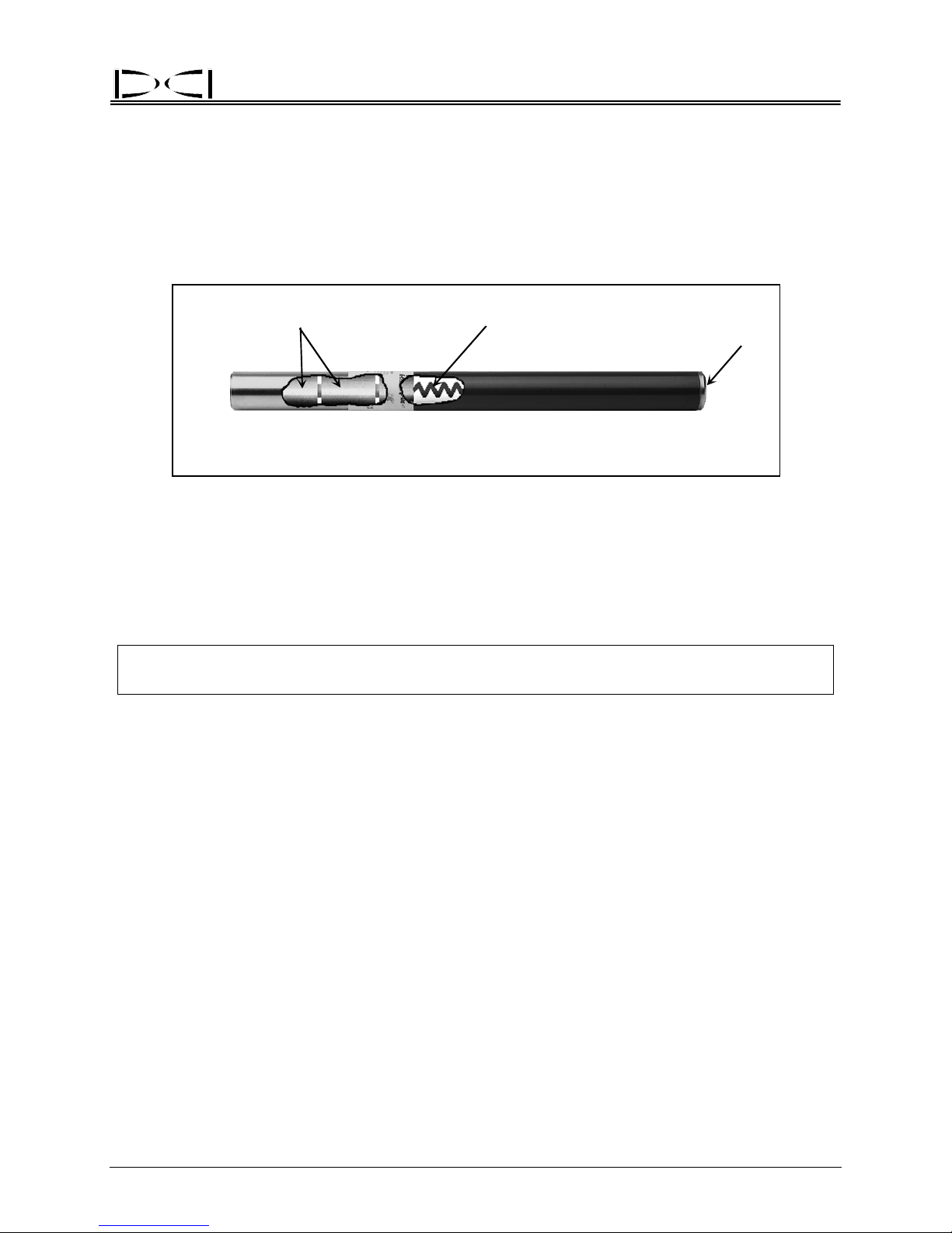
Transmitter
Batteries Antenna
Index Slot
Back
DigiTrak Tr
A transmitter (also referred to as a sonde, beacon, or probe) is a device that emits electromagnetic
signals at radio frequencies and fits inside the tool housing. It transmits information regarding its location,
position, and heading. The transmitter emits signals that the receiver “hears” and converts into the
information shown in the three display windows. The range of a transmitter depends upon its type. For
more information, see the DigiTrak Transmitter Specifications table at the end of this section.
NOTE:
The range of any transmitter with any DCI receiver is dependent upon the amount of interference at a job site. The range decreases as interference increases.
ansmitter
Front
How a Transmitter Works
The transmitter emits two types of signals, both at approximately 33 kHz. The first signal is the depth or
signal strength. The second signal sends pitch, roll, and battery and temperature status information. The
pitch/roll signal has a wider bandwidth than the depth signal and occasionally may be more susceptible to
interference. For more information about interference and transmitter signal interruption, see the Signal
Interference Section, the Troubleshooting Section, and “Electrical Interference/Background Noise Check”
in the Signal Interference Section.
With the trigger released, verify that the transmitter is sending adequate pitch and roll information to the
receiver—the top left window of the receiver will
to wait for two consecutive squiggles with the same pitch and roll information before relying on the information to give any steering commands. Waiting assures confirmation of an accurate reading. As the
transmitter reaches its maximum range, the squiggles will become less frequent than every 2.5 seconds.
For further information on pitch/roll and the squiggle, see the Operational Tests Section (particularly
“Transmitter Tests”).
Transmitter pitch is displayed in percent slope as 1% i
pitch transmitter) in the top left window of the receiver with the trigger released. For more information see
“Sensitive-Pitch Transmitters” later in this section.
DigiTrak® Mark III Operator’s Manual 19
flash a squiggle (“~”) every 2.5 seconds. It is important
ncrements or 0.1% increments (if using a sensitive-
Page 28
®
Transmitter
Transmitter roll positions are displayed digitally as a whole number from 1 through 12 in the top right
window with the receiver’s trigger released. The numbers correspond to the hour hand of a clock. At the
12 o’clock position, the transmitter is oriented with the index slot at the top. The tapered or flattened surface of the drill head should be indexed to this position.
Batteries
All DCI transmitters (except the cable transmitter) are powered by C-cell alkaline batteries (see Transmitter Specifications at the end of this section). The long-range transmitters, including the sensitive-pitch
transmitters, have a 4 C-cell option for longer bores. The status of the batteries in the transmitter can be
viewed (in percent life remaining) using the receiver’s display (see “Battery Status Display” below). The
cable transmitter requires an above-ground power supply (see Transmitter Section).
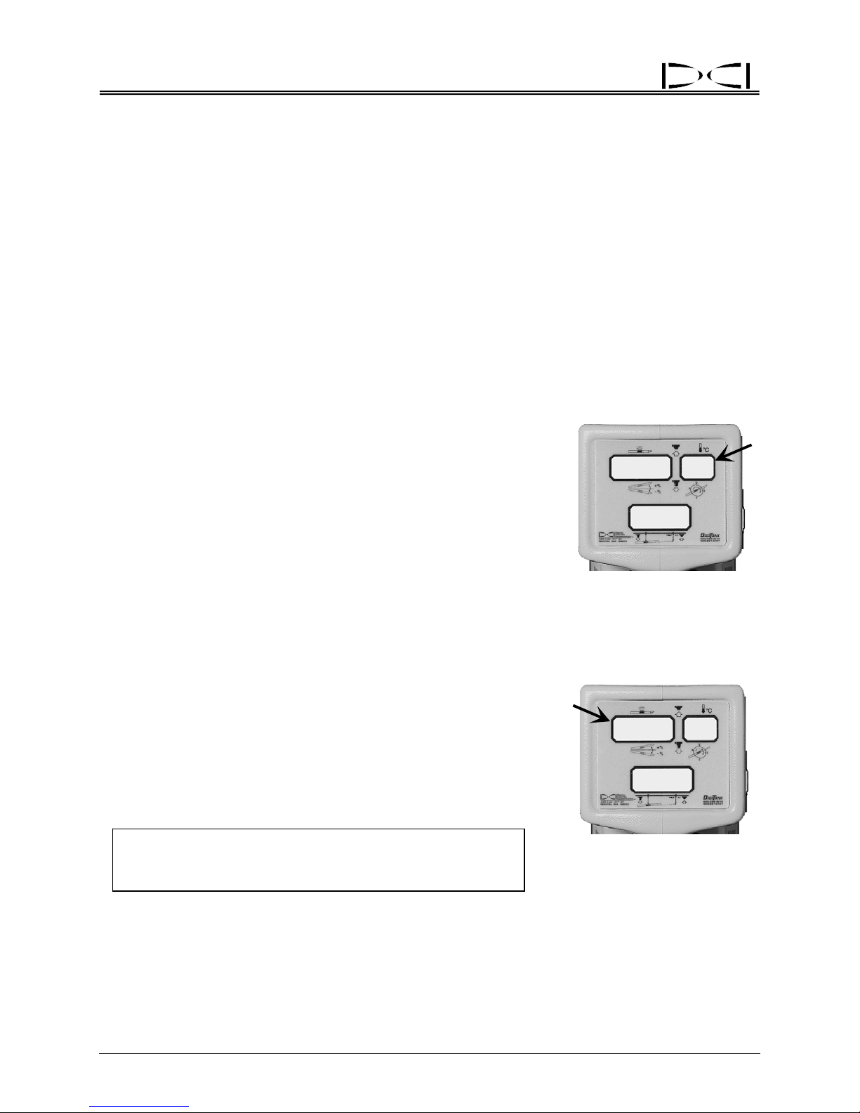
Temperature Display
Transmitter temperature is displayed i
increase in the transmitter’s temperature will flash for 2 seconds in the
top right window of the receiver and the remote display. The receiver
will also sound audible tones that increase in intensity as the
transmitter’s temperature increases. When the remote display has a
DataLog module attached, the transmitter’s temperature increase
tones will be heard at the drill. To manually view the temperature of
the transmitter, simply hold in the receiver’s trigger; the temperature
will flash in the top right window. Receivers with pre-5.0 series
firmware will display the temperature in the top right window while the
trigger is held in, but it will not flash. To view the transmitter temperature at the drill, see the Remote Display Section.
n degrees Celsius. Every 4°C
Battery Status Display
The percent of battery life remaining in the transmitter is displayed in
the top left windo
transmitter’s battery status in percent remaining life is displayed as
100, 90, 75, 50, 25, 10, 5, or 0. (The receiver’s battery status in
percent remaining life is also displayed during this 2-second interval in
the top right window as 99, 90, 75, 50, 25, 10, 5, or 0.) If the word
BAT occurs in the top left window when not viewing the transmitter’s
battery status, the transmitter batteries must be replaced.
NOTE:
w for 2 seconds upon releasing a held-in trigger. The
Neither the temperature nor the battery status will
be available until 4 minutes after initial start-up for
receivers with 5.0 series or later firmware.
+
6 I 9
~
Transmitter Temperature
Display (Fla
905690
BAT
Transmitter Battery Status
in Percent
22
I
26
shing)
Remaining Life
Temperature Overheat
All transmitters have a temperature overheat indicator (temp dot) that has an outer yellow ring with a 1/8inch (3-mm) white dot in the center. This temp dot is located on the stainless-steel front end cap. On
older transmitters, the temp dot is located inside the battery compartment next to the battery terminal.
20 DigiTrak® Mark III Operator’s Manual
Page 29

®
Transmitter
The temp dot should be white if the transmitter has not been exposed to excessive heat. If the temp dot
is silver or gray, it indicates the transmitter has been exposed to heat but not in excess of the specifications. A black temp dot indicates the transmitter has been exposed to temperatures in excess of
104°C (220°F). The transmitter will shut off at about 80°C.
If the transmitter overheats, it may appear to operate norm
tures greatly increases the likelihood of inaccurate information and will contribute to premature failure of
the transmitter. The warranty does not apply to any transmitter that has been overheated or to any
transmitter where the temp dot has been removed. Avoid overheating by practicing proper drilling
techniques. Abrasive soils, clogged ports, inadequate mud flow, and poorly mixed mud can contribute
significantly to the risk of an overheated transmitter.
The transmitter temperature warnings are listed in th
versions greater than 3.76. Drilling should be suspended when temperatures reach 35°C to permit
cooling.
ally; however, exposure to excessive tempera-
e following table. These warnings apply for firmware
Transmitter Temperature Warnings
Temperature Range Warning Signal
14°C and below
15°C to 35°C One double tone with every 4°C increase in temperature.
36°C to 45°C Two double tones with every 4°C increase in temperature.
45°C to 60°C Three double tones with every 4°C increase in temperature.
60°C and above
No audio or visual warnings.
Audible error tones (two long tones) and the bottom window will flash;
1999 may ap
pear when the transmitter shuts down at about 80°C.
Sleep Mode (Automatic Shutoff)
The transmitter will shut down (go into “sleep” mode) to conserve battery power if it is stationary for 15
minutes. The transmitter sleep mode can be recognized on the receiver as “1999” in the bottom window
(no signal). To “wake up” the transmitter, simply rotate the drill string. For more information on 1999 in
the bottom window, see the Operational Tests Section, particularly “Transmitter Tests,” and the Troubleshooting Section.
Transmitters manufactured prior to January 1997 have what is called “12 o’
that when the transmitter is in the 12 o’clock position, the transmitter will shut off for 10 seconds and 1999
will be displayed in the bottom window of the receiver.
clock shutoff.” This means
Verifying Proper Fit of Transmitter in Housing
Before installing a transmitter into a housing, read the information given below about how the transmitter
should fit into the housing. You may then proceed to the installation instructions that follow.
How Transmitter Should Fit in Housing
The transmitter must fit snugly into the housing. The transmitter has an index slot in the front end cap
fits onto the anti-roll pin (key) in the housing. Wrap the transmitter with tape or O-rings to eliminate
that
DigiTrak® Mark III Operator’s Manual 21
Page 30

Transmitter
any free space between the transmitter and the
side walls of the housing. If necessary,
fabricate an “insert” behind the transmitter to
ensure a snug fit. When wrapping with tape,
be sure that the pitch will not be offset. If more
tape is on one end than the other, the transmitter will not be level in the housing. Also, be
sure that metal-to-metal contact is avoided.
Before purchasing a new housing, place a
transmitter in
Also check that the index slot fits snugly over
the key in the housing. If the key is too narrow,
the transmitter can rotate and cause damage
to the index slot. There are particular “wear
patterns” that occur on transmitters that do not
fit properly in the housing. If you send a
transmitter to DCI for testing, please specify
what type of housing you are using.
side and check for a snug fit.
Temp Dot
Front End Cap of Transmitter
Showing Te
mp Dot and Index Slot
®
Index Slot at
6 o'clock Posi t ion
Because the transmitter’s antenna is positioned centrally (a
that the windows or slots in the housing (through which the signal is emitted) are positioned to allow the
transmitter’s signal to emit with minimal restriction. The slots must number at least five and have a length
of no less than 8 inches (20 cm). These slots must be centered directly over the midpoint of the
transmitter. The width of the slots may be as narrow as necessary to maintain housing strength.
(Drawings showing the proper slot width, length, and positioning can be obtained by request from DCI.)
These slots must not have any filler material containing metal particles, e.g., liquid steel.
To install a transmitter in the housing:
1. Examine the transmitter to verify that there is n
springs inside the battery compartment have not been permanently compressed, and that the temperature indicator (temp dot) located at the front end of the transmitter is not black.
2. Insert the correct number of C-cell alkaline batteries into the battery compartment with the positive
end in first. Place
3. Place the transmitter in the housing with the index sl
above in this subsection. The 12 o’clock position should correspond to the tapered or flattened surface of a typical directional drill head pointed upward.
4. Verify that the transmitter is emitting the approp
conduct other tests as discussed in the
NOTE: Place the transmit
cap over battery compartment and tighten. (See “Batteries” below.)
System Operating Instructions Section before you start drilling.
ter in the housing and verify that pitch readings remain the same
when the housing is held level and rotated through at least four of the 12 clock
positions.
s shown on the previous page), it is important
o moisture inside the battery compartment, that the
ot over the anti-roll pin positioned as discussed
riate amount of signal (see Operational Tests) and
22 DigiTrak® Mark III Operator’s Manual
Page 31

®
Transmitter
Locating the Transmitter
The properties of the transmitter’s magnetic field enable the receiver to locate the transmitter accurately
below ground. The transmitter emits an elliptically shaped field that allows the receiver to locate the
transmitter using three specific locations, not just the highest signal. These locations are referred to as
the front and rear negative locate points (FNLP and RNLP) and the positive locate line. For more
information about locating the transmitter, see the Locating Section.
The transmitter’s locate line and points will only be accurately received if the receiver is maintained in a
level position.
The receiver is ergonomically designed to level itself while easily depressing the trigger.
Sensitive-Pitch Transmitters
The sensitive-pitch transmitters are designed for gravity sewer installations where pitch must be known in
increments smaller than 1%. DCI’s sensitive-pitch transmitters operate exactly the same as regular-pitch
transmitters except that the pitch is measured and displayed in one-tenth percent (0.1%) increments.
(1%)
The transmitter’s pitch, which is displayed in the receiver’s top lef
point; therefore a pitch reading of 45 would correspond to a pitch reading of 4.5%.
The maximum pitch that can be measured and displayed with sensitive-pitch transmitters is 10%. A
readi
ng of 10% will correspond to a display of 100 in the receiver’s top left window. If the launch or exit
portions of the borepath exceed 10%, it may be preferable to drill those sections using a regular-pitch
transmitter and then use a sensitive-pitch transmitter for the remainder.
Tips for drilling with a sensitive-pitch transmitter:
1. Plan the borepath and position the drill rig so that the laun
2. Using a level test surface, verify that the pitch does not fluctuate as the transmitter is rolled through all
12 clo
ck positions. If it does, make note of the variation.
3. Perform the same test with the transmitter in the housing. This will indicate whet
being held level in the housing.
4. Take pitch readings with the transmitter positioned at 9 o
back a few inches from the front of the tunnel, to obtain greatest accuracy of sensitivity.
5. Verify that the tool is at the correct depth and pitch before drilling criti
borepath. Incorrect initial positioning can result in exceeding the steering capabilities of a drilling tool.
If the drill tool is not correctly positioned at the beginning, this error can compound and/or you may
not be able to steer the tool to recover.
t window, does not show the decimal
ch and exit profiles are gently sloped.
her the transmitter is
r 3 o’clock, after the tool has been pulled
cally sloped portions of the
Transmitter as an Inclinometer
It is possible to use the transmitter as an inclinometer to measure the slope of the ground above the borepath. This can be useful if the borepath is targeted at a constant depth below the surface. Simply match
the transmitter’s pitch to the carefully measured slope of the ground and the depth should be constant.
DigiTrak® Mark III Operator’s Manual 23
Page 32

®
Transmitter
Serial Numbers
All transmitters are identified by a serial number stamped in the metal battery compartment near the
plastic/stainless steel contact.
NOTE: Whe
n calling DCI Customer Service be prepared to supply the serial number.
Specifications
The specifications given below assume the use of the latest model (Mark III) of the DigiTrak Receiver. All
Mark III Transmitters operate at a frequency of approximately 33 kHz. Pitch updates occur every 2.5 seconds, and roll updates occur every 0.25 second. All transmitters revert to sleep mode after 15 minutes
except the cabletransmitters, which are turned off by disconnecting the above-ground battery source. All
transmitters also transmit information regarding transmitter temperature and estimated battery life
remaining.
DigiTrak Transmitter Specifications
Model /
Color
DS
Blue
DT
Yellow
DX
Red
D4X
Red
D4XP
Magenta
DXP
Magenta
Type of
Transmitter
Short Range
Standard Range
Long Range
Long-Range w/
Extended Life
D4X w/ Sensitive
Pitch (0.1%)
DX w/ Sensitive
Pitch (0.1%)
Length x
Diameter
8 in. x 1.00 in.
20 cm x 2.54 cm
15 in. x 1.25 in.
38 cm x 3.125 cm
15 in. x 1.25 in.
38 cm x 3.125 cm
19 in. x 1.25 in.
48 cm x 3.125 cm
19 in. x 1.25 in.
48 cm x 3.125 cm
15 in. x 1.25 in.
38 cm x 3.125 cm
Signal
Range*
15 ft
4.6 m
40 ft
12.2 m
70 ft
21.3 m
70 ft
21.3 m
70 ft
21.3 m
70 ft
21.3 m
Battery
Type
1 AA-cell alkaline
12 hou
2 C-cell alkaline
30 hou
200 hours sleep
2 C-cell alkaline
20 hou
200 hours sleep
4 C-cell alkaline
40 hou
400 hours sleep
4 C-cell alkaline
40 hou
400 hours sleep
2 C-cell alkaline
20 hou
200 hours sleep
rs awake
50 hours sleep
rs awake
rs awake
rs awake
rs awake
rs awake
Temp.
Rating Weight
180°F
°C
82
220°F
104°C
220°F
104°C
220°F
104°C
220°F
104°C
220°F
104°C
8.4 oz
240 g
1.4 lb
635 g
1.4 lb
635 g
1.85 lb
840 g
1.85 lb
840 g
1.4 lb
635 g
DCX
Green
DCP
Magenta
*Depth/distance accuracy is ±5% absolute.
3-3000-00d-F
24 DigiTrak® Mark III Operator’s Manual
Cable
Transmitter
DC w/ Sensitive
Pitch (0.1%)
15 in. x 1.25 in.
38 cm x 3.125 cm
15 in. x 1.25 in.
38 cm x 3.125 cm
140 ft
42.7 m
140 ft
42.7 m
12V to 28V DC
cable power
12V to 28V DC
cable power
180°F
°C
82
180°F
°C
82
1.2 lb
545 g
1.2 lb
545 g
Page 33

®
DIGITAL CONTROL INCORPORATED
Remote Display System
Pitch or
Battery
Status
Depth/Distance or
Predicted Depth
Channel Selector
The DigiTrak Remote Display unit is typically positioned where
tor. The remote display uses telemetry to display some of the information displayed by the receiver. The
remote display can also be used for remote steering when walkover tracking is not possible. The left side
of the remote display’s panel is identical to the receiver’s display panel. The long window to the upper
right is used for remote steering (see below).
The remote display will show the drill operator the transmitter’s
status, and predicted depth. It will not display signal strength or the plus/minus (“+/–”) symbols.
Roll or
Temperature
~
I 5
8
I
I
Remote Display Unit
Remote
Steering
Window
8
On/Off Button
it will be readily visible by the drill opera-
pitch, roll, depth, temperature, battery
Mounting
Screws
for DataLog
Module
The receiver must have remote capability to send a signal to the rem
capability are identified by a large orange arrow below the battery door. All receivers can be upgraded to
remote capability by DCI. The maximum separation between the receiver and the remote display can
range up to about 4000 ft (1220 m) depending upon interference and topographic features.
The DigiTrak System uses ultrahigh-frequency telemetry to com
remote display. Both the receiver and the remote display must have the same type of telemetry to
communicate properly.
DigiTrak® Mark III Operator’s Manual 25
ote display; receivers with this
municate between the receiver and the
Page 34

Remote Display
On/Off and Setting the Channel
To turn the unit on, place a fully charged DigiTrak battery pack into the battery compartment, terminal end
in first, then push the black button on the front of the display panel.
®
Select one of the four channels. Note that chan
use a second frequency. Be sure to change the channel selection on the receiver to match that selected
on the remote display (see “Changing the Receiver’s Channel Setting” in the Receiver Section).
NOTE:
The transmitter information on the remote display will be the same as that at the receiver, except the
Remote will not display signal strength nor the “+/–” locating symbols. The remote display will continue to
display pitch, roll, and distance along with the flashing squiggle (“~”) in the top left window, indicating that
updates are being received. You should always wait for two consecutive updates with the same pitch/roll
information before making a steering action.
The remote display has no automatic shutoff function. To turn the
ship a remote display or receiver with a battery in the battery compartment.
A zero (0) on the receiver indicates that the receiver’s telemetry is shut off and no signal will
be sent back to the drill, which will result in “dashes” across the three display windows on
the Remote. Setting the receiver to channel 0 may be useful for conserving receiver battery
power.
nels 1 and 3 use one frequency, and channels 2 and 4
unit off, push the on/off button. Never
Transmitter Temperature and Battery Status
Remote displays with firmware vers ions of 3.9 or later automatically display the transmitter’s temperature
and battery status in the top right window for 2 seconds when a 4°C temperature increase occurs. The
transmitter’s temperature and battery status can also be viewed on command by turning the Remote off
and then back on. Remotes with older firmware versions (3.8 or earlier) will display transmitter status
automatically every 30 seconds but not at start-up. The drill operator will hear temperature increase
tones when a DataLog module is attached to the remote display.
For more information on transmitter temperature display inte
DCI’s web page located at www.digitrak.com
see “Finding Firmware Version” below and, for the receiver, see “Finding Firmware Version” in the
Receiver Section.
26 DigiTrak® Mark III Operator’s Manual
rvals, see firmware update information on
. To determine the remote display unit’s firmware version,
Page 35

®
Remote Display
Remote Steering
Remote steering is used to cross streams and
road
ways or other inaccessible areas when it is
not possible to walk over the transmitter. To
initiate the remote steering capability, the
receiver is placed in front of the transmitter as
the “target.” The distance the receiver can be
placed ahead is limited by the range of the
transmitter and interference.
Receiver Placed
on Side (Drill
Path Is Aligned
with Target Point
on Front Panel)
Target Point
With the transmitter powe
red up and in the
housing ready to drill, walk with the receiver
(powered up and trigger held in) on the surface
over the intended borepath to the “target” location. Verify that the receiver displays at least
250 points of signal at target location. Place
the receiver on its side so that the orange arrow
on the receiver points toward the ground. The
target point on the receiver is the center point
between the two depth/locating antenna
screws. The receiver’s front panel should face
the drill. To position the receiver properly, it is
important to pivot the receiver using the center
point between the two antenna screws as the
axis of rotation. When the receiver is properly
pivoted on this axis, the vertical bars (indicating
the transmitter’s position) will line up with the
two triangles (indicating the target) in the center
of the remote steering window. When the
receiver is in its target position, its top surface
must be level. If necessary, place shims under
the receiver to level it.
On the remote steering window, the receiver
et) is represented by two triangles, one
(targ
above and one below the window; the
transmitter is represented by a vertical bar in
this window (see photo on next page). If the bar
is to the right of the triangles, the tool will need
to be steered to the left so that the steering indicator is lined up with the triangles; if the bar is to
the left of the triangles, the tool will need to be
steered to the right.
Transmitter
Under
Roadway
Drill
Setting up DigiTrak Receiver
for Rem
Depth/Locating
Antenna Screws
Target Point
ote Steering
Drill Path
Axis of
Rotation
Front Panel
DigiTrak® Mark III Operator’s Manual 27
Using DigiTrak Receiver for Remote Steering
Page 36

Remote Display
®
Vertical Bar
(Represents
Transmitter)
~
I 5
Align Vertical Bar (Transmitter) with Triangles (Receiver)
in Remote Steering Wind
As the transmitter approaches the target (receiver), the FNLP
receiver. At this point, the remote steering is no longer accurate and the receiver must be moved to a
new farther-out location. The distance between the transmitter and the FNLP is dependent upon the
depth and pitch of the transmitter and the topography. When the pitch of the transmitter is 10% or less
and the ground is parallel to the transmitter, the FNLP is ahead of the transmitter by approximately 0.7
times the transmitter depth. As an example, if the transmitter is 8 ft (2.4 m) below ground, the FNLP will
be approximately 5.6 ft (1.7 m) in front of the transmitter (8 ft x 0.7 = 5.6 ft).
Because the receiver has not been used as a walkover tool to
remote steering, it will be necessary to calculate the depth based on the pitch information. For more
information about calculating the depth based on pitch, see “Running Off Pitch or Calculating Depth from
Pitch” in the Locating Section.
I
8
I 8
ow to Steer Tool
will pass underneath and go past the
track the depth of the transmitter during
Steering
Triangles
(Represent
Receiver)
Finding Firmware Version
The firmware version installed in the remote display can be identified as follows:
1. Place a battery pack in the unit.
2. Click the “on” button.
3. The firmware version will be displayed in the top left window for 2 seconds. When the firmware
version i
displayed as 377.
After releasing the button, the unit will complete start-up and then be ready for use.
s displayed, the decimal point will not be shown. For instance, firmware version 3.77 will be
DataLog Capability
Current Mark III Remote Displays have two metal studs protruding from the right side of the display case
for optional DataLog module attachment. The DataLog module also has a speaker, so the drill operator
hears the transmitter temperature increase tones and logging tones. Call DCI if you are interested in
obtaining more information on the DataLog Mapping System.
3-3000-00e-F
28 DigiTrak® Mark III Operator’s Manual
Page 37

®
DIGITAL CONTROL INCORPORATED
Battery Charger
DigiTrak
Battery Pack
AC Power
Cord
Unexposed Terminal
-- Do Not Expos e -DC Power
Cord
Negative
Terminal
Positive
Terminal
DigiTrak Battery Charger
Both the DigiTrak Receiver and the Remote Display use
is provided with the system together with a DigiTrak Battery Charger. The battery pack should be fully
discharged before recharging; this is known as conditioning the battery.
The battery charger can be powered from AC or DC an
cycle designed to remove the “memory effect” from the battery. The charger will operate from any AC
voltage (wall outlet) between 85V and 240V without modification (you may need to convert the plug).
This allows the same battery charger to be used in many different countries. The battery charger is also
equipped with an automotive cigarette lighter adapter for 12V or 28V DC charging. The older-style chargers do not have a conditioning cycle, so the batteries should be used until fully discharged before they
are put in the charger to be recharged. See “Conditioning a Battery Manually” later in this section for
instructions.
NiCad batteries can develop a memory. This condition i
it has been completely discharged. If this occurs, it will appear to the user that the battery has a shorter
life. Batteries with this condition can be restored to normal function by using the conditioning cycle. It is
not necessary to condition a battery if it has been completely discharged through normal use. Excessive
conditioning does not improve battery performance and only serves to shorten battery life. If a battery
fails to improve after two or three conditioning cycles, it should be replaced.
a DigiTrak rechargeable NiCad battery pack that
d is equipped with a conditioning or discharge
s caused by repeatedly charging a battery before
Control
Panel
The voltage on a fully charged battery is between 16.5V and 17.1
at 14.0V.
DigiTrak® Mark III Operator’s Manual 29
V. A battery is considered discharged
Page 38

®
Battery Charger
Only two terminals are exposed on the DCI NiCad battery pack, although a third terminal appears to be
available. If the third terminal accidentally becomes exposed, do not try to charge the battery pack or you
may damage the battery charger. Such a battery can also damage the remote display or receiver. A
damaged battery pack will require replacement.
Charging a Battery
NOTE: Only charge DigiTrak NiCad batteries in the battery charger. Charging or using other
types of batteries may damage the charger, the receiver, or the remote display and will
void the warranty.
1. Plug the charger into either a wall outlet or the cigarette lighter of a vehicle.
2. Place a discharged battery into the charger with the terminal end making contact with the springs.
The red light on the left will illuminate, indicating that the unit is charging.
3. The battery will take between 20 minutes and 2
charge. When the charging cycle has been completed, the green light on the right will illuminate,
indicating that the battery has completed the charging cycle and is ready for use.
4. If the battery is left in the charger, a trickle charge cy
tain the optimum battery level while the battery is in the charger. The green light will stay illuminated,
indicating the battery is fully charged and ready for use.
Red Light
Indicates Unit
Is Charging
Charge Button
hours to charge, depending on the extent of dis-
cle will continue to “top off” the battery and main-
Green Light :
– Solid
Battery Is
Fully Charged
– Blinking
Battery Is Being
Conditioned
Condition Button
Indicates
Indicates
30 DigiTrak® Mark III Operator’s Manual
Serial Number
Battery Charger Control Panel
Page 39

®
Battery Charger
Conditioning a Battery in the Charger
1. Place the battery into the charger.
2. Press the right button on the charger (marked with a
out and the green light on the right will start to blink. This indicates that the battery is being conditioned. The conditioning cycle may last for up to 7 hours, depending on the remaining charge in the
battery.
3. When the conditioning cycle is compl
red light turning on and the flashing green light going out. The battery is discharged to 12V before
charging begins.
4. When the battery has reached full charge, the green light will illuminate indi
battery is ready.
eted, a charging cycle will automatically start, indicated by the
curved arrow). The red light on the left will go
cating a fully charged
Conditioning a Battery Manually
To condition a DCI battery pack, you simply
need a low-wattage 12V light (such as a small
automotive side light or an interior light bulb)
and electrical wires to connect the battery pack
to the light as shown.
The length of time required to condition a
NiCad batte
hours. The battery should not be discharged
beyond 12V. Measure the voltage across the
light to confirm the battery is discharged to no
lower than 12V.
ry manually can range from 1 to 7
Setup for Discharging a Battery Manually
DCI
Battery
Pack
12-Volt
Backup
Light
Indicator Lights and Meanings
Action / Meaning Red Light Green Light
Unit is off or no battery is in unit Off Off
Unit is charging a battery On Off
Battery is charged Off On
Unit is discharging a battery Off Blinking
NOTE: If a battery is left in the charger during a power interruption, the red or green light may flash and
the battery will begin to discharge on its own. Simply remove and replace the battery pack after the
power has resumed.
DigiTrak® Mark III Operator’s Manual 31
Unit is malfunctioning Blinking Off
Page 40

Battery Charger
Notes
®
3-3000-00f-F
32 DigiTrak® Mark III Operator’s Manual
Page 41

®
DIGITAL CONTROL INCORPORATED
System Operating Instructions
Start-up Procedure
1. Ensure that the transmitter has fresh C-cell alkaline batteries installed and place the transmitter inside
the tool housing.
2. Click the receiver trigger, located under the handle.
sound.
3. Ensure that the receiver’s battery pack does not indic
display “BAT”).
4. Complete electrical interference ch
5. Verify that the receiver is displ
window. The squiggle should briefly flash every 2.5 seconds.
6. Roll the transmitter housing on a flat surface (with the trans
clock positions match the display in the top right window.
7. Lay a tape measure between the transm
8. Complete the calibration procedure (see “Calibrating the Receiver” in the Receiver Section).
9. Verify that the distance displayed in the bottom wi
varying distances, in particular 1.5 times the target depth for the intended borepath.
eck (see Operational Tests Section).
aying pitch/roll updates by watching the squiggle (“~”) in the top left
itter in the housing and the receiver.
All the displays will illuminate, and a tone will
ate low battery power (bottom window would
mitter inside) to verify that the transmitter’s
ndow matches the distance on the tape measure at
Shutdown Procedure
The receiver will automatically shut itself off after 15 minutes of no signal received. To turn the unit off
when a signal is present, click the trigger once and, during the tone, quickly click 4 times. All windows will
blank out, indicating that the unit is off. To turn off a pre-5.0 series firmware receiver when a signal is
present, you must manually remove the battery. (For more information on the 5.0 series firmware and
operating/display differences, see “Clicking vs. Holding the Trigger” and “5.0 Series Firmware Functions”
in the Receiver Section.)
Moisture and Temperature Avoidance
The DigiTrak Receiver and Remote Display are rainproof but not waterproof and should be protected
from immersion or excessive splashing. In addition, condensation inside the equipment can occur if the
equipment is subjected to repeated large temperature changes. Avoid sudden, large temperature
changes to protect from condensation buildup. Placing a cold beverage can on the display window will
confirm the presence of moisture if there is a ring of droplets after the can is removed.
Contact DCI at 425-251-0559 or 800-288-3610 for field “drying” technique.
®
DigiTrak
Mark III Operator’s Manual 33
Page 42

®
System Operation
Optimal Operating Temperatures
The minimum operating temperature for the DigiTrak locating equipment is -4°F (-20°C). All batteryoperated equipment is prone to “capacity loss” in cold temperatures. Excessively cold temperatures can
result in slow display response and increased measurement errors. The maximum temperature for
receivers and remote displays is 176°F (80°C). Operation in direct sunlight can cause temperatures
greatly in excess of the air temperature. The maximum temperature for transmitters varies between
180°F (82°C) and 220°F (104°C) depending on the model—see Transmitter Specifications at end of
Transmitter Section.
General Maintenance
Please observe the following general maintenance requirements:
¾
Turn off all equipment when not in use. Remove the batteries from the receiver and/or the remote
display when done using the equipment.
¾
Do not ship any DigiTrak locating equipment with the batteries inside. Always remove the batteries
from the equipment before shipping.
Do not use chemicals to clean the transmitter.
¾
¾
Do not leave the transmitter in the housing overnight.
¾
Store the DigiTrak equipment in cases, away from heat, cold, and moisture. Perform tests to confirm
proper operations.
Do not disassemble or attempt to repair DigiTrak locating equipment.
¾
¾
Contact DCI at 425-251-0559 or 800-288-3610 or visit our web site at www.digitrak.com
current with the latest innovations.
to stay
3-3000-00g-F
34 DigiTrak® Mark III Operator’s Manual
Page 43

®
DIGITAL CONTROL INCORPORATED
Signal Interference
Before drilling (preferably before bidding on
evaluated. Interference can reduce the transmitter’s range or cause variable readings and possibly result
in job slowdowns. Interference comes from two different types of sources: active and passive.
a project) the interference potential at your site(s) should be
Active interference is
the DigiTrak locating equipment. Most electrical devices emit signals. Because DCI receivers have two
types of antennas in them (depth and roll/pitch), it is possible to have interference that affects one or both
signals. Some examples of active interference are traffic signal loops, buried dog fences, cathodic protection, radio communications, microwave towers, cable TV, fiber-trace lines, utility data transmissions,
security systems, power lines, and phone lines.
Passive interference sou
transmitter’s signal. This can cause erroneous depth readings or, in extreme cases, no signal, i.e., “1999”
in the bottom window. In addition, the FNLP and RNLP (discussed in the Locating Section) may be
affected. Some examples of passive interference are:
¾
Metal (pipes, rebar, trench plate, chain-link fence, engine blocks, etc.) – Metal acts as an antenna
and can therefore draw the receiver to erroneous locations.
Saltwater – Saltwater affects conductivity and can contribute to signal degradation. Before drilling in
¾
saltwater or brackish water, conduct a range test in the salt or brackish water to determine the
amount of signal loss (see “Transmitter Salt Water Range Test” in the Operational Tests Section).
Depth error will be increased and roll/pitch range will be reduced. A 2-point calibration can help
reduce the error (see “2-Point Calibration Procedure ” in the Receiver Section).
¾
Conductive earth – Drilling through formations with high metal ore content can degrade the transmitter’s signal and cause depth errors and reduced roll/pitch range. Again, a 2-point calibration can
be used to reduce the depth error (see “2-Point Calibration Procedure” in the Receiver Section).
To install your product accurately and safely, the location of every
intended borepath should be confirmed by potholing. This task is the first step in familiarizing yourself
with the interference potentials near the intended borepath. The next step is to conduct an electrical
interference/background noise check, as described below.
also known as electrical interference or noise and can have varying effects upon
rces (listed below) can reduce the amount of signal received or reradiate the
below-ground structure proximal to the
Electrical Interference/Background Noise Check
An electrical interference check will familiarize you with your site conditions and help determine potential
locations along the borepath where the transmitter’s signal may encounter interference. Things that can
cause interference include the following: traffic signal loops, cable TV, saltwater, microwave towers, utility
data transmissions, power lines, fiber-trace lines, security systems, invisible (buried) dog fences, large
metal objects, rebar, and cathodic protection.
DigiTrak® Mark III Operator’s Manual 35
Page 44

®
Signal Interference
There are two steps to the electrical interference/background noise check. The first step takes one
person; the second step requires two people.
1. With the transmitter off, test the amount of noise the rec
walking the borepath from the launch to the exit location. Watch the signal strength (top left window)
and note the locations where the signal strength changes. Typically, a reading greater than 150
indicates background noise that may interfere with the magnitude and shape of the transmitter’s
magnetic field lines and therefore alter the depth/distance readings and the locate points an d line.
2. At the exit end of the borepath, install batteries in the transmitter to activate it. Then have one person
carry the transmitter along the bor
distance approximately one and one-half (1.5) times the target depth of your installation while
carrying the receiver. Do not hold in the trigger on the receiver; simply watch all the windows for any
changes in the transmitter’s information. Verify that the squiggle (“~”) in the top left window is flashing
every 2.5 seconds (indicating you are receiving pitch/roll updates). In particular, note any locations
where the display information inexplicably changes or where the pitch and roll updates become
infrequent.
See suggestions for dealing with interference in the following section.
epath back to the drill while the other person walks in parallel at a
eiver hears by holding in the trigger and
Suggestions for Dealing with Interference
Every job site warrants an electrical interference/background noise check no matter how remote and
interference-free your job site appears to be.
If pitch and roll (along with transmitter battery and temperatu
sometimes possible to recover the signal by walking away from the transmitter in several directions,
staying within the published range. The objective is to move away from the interference source.
re status) suddenly stop updating, it is
Another solution is to use a stronger-sig
range DT Transmitter, then try a red long-range DX Transmitter, and if you’re using a red DX Transmitter,
then try the Cable Transmitter. (See the Cable Transmitter Section.)
3-3000-00h-F
nal-strength transmitter. For example, if using a yellow standard-
36 DigiTrak® Mark III Operator’s Manual
Page 45

®
DIGITAL CONTROL INCORPORATED
Operational Tests
Self-Test for Mark III Receivers
Mark III Receivers have the capability of completing a diagnostic self-test to confirm proper operation.
This test must be conducted without a transmitter and in an interference-free environment. The self-test
procedure is conducted at start-up by clicking the trigger in a specific sequence.
1. Place a fully charged DigiTrak battery into the re
2. At the tone, quickly click the trigger 3 times (observe the number 3 in the bottom window). The test
tak
es approximately 15 seconds to complete.
3. If no problem is detected, the receiver will sound 3 tones, and turn
4. If the receiver detects a problem, it will display an
long tones.
5. An error code of “001” indicates high background no
duct the self-test again.
For assistance with troubleshooting an error code call DCI.
ceiver and click the trigger once.
itself off.
error code in the top left window accompanied by 2
ise; move to an interference-free area and con-
Receiver Balance Check
If the receiver appears to be exhibiting a consistent left or right error, it is possible that the antennas in the
receiver are out of balance. It is also possible to find the transmitter further to the left or right if you use
only signal strength to locate the transmitter or if there is an interference source within proximity. The
transmitter’s location (depth and left/right position) should always be determined using the front and rear
negative locate points, not relying solely on peak signal.
To determine if the receiver’s
antenn
plete the following test:
as are in balance, com-
1. Place the transmitter on
the grou
front (or behind) about 10
to 12 ft (3 to 3.7 m) away
and a little to the left or
right side of the axis line
that extends from both
ends of the transmitter, as
shown in the drawing.
2. Hold the receiver perpendic
with the trigger held in.
DigiTrak® Mark III Operator’s Manual 37
nd and step out in
ular to the transmitter
Plus (+)
Changes to
Minus (–)
Axis
Line
Receiver Balance Test – Make
on same line coming from both directions.
Plus (+)
Changes to
Minus (–)
Axis
Line
sure “+” changes to “–”
Page 46

Operational Tests
3. Walk toward the axis line and watch for the plus (“+”) sign in the top left window to change to a minus
(“–”) sign. Note this location.
®
4. Continue past the axis line, then stop a
direction. Walk back toward the axis line from this opposite side and find
changes to a “–”.
5. These two
assistance.
locations should be in the same place and lie on the axis line. If not, call DCI for
nd turn the receiver 180° around so it is facing in the opposite
the location where the “+”
Receiver Gain Test
Another test to confirm that the receiver is displaying the depth information correctly is to conduct a gain
test. This is a check of the receiver’s scaling system for depth and is similar to the old “walkie talkie” gain.
To complete the gain test, you will need an active transmitter, a tape measure, and the receiver.
1. Run the tape measure from the side of the transmitt
1-point calibration (see “Calibrating the Receiver” in the Receiver Section). The tape measure should
extend out to the transmitter’s maximum range (see “Specifications” table in the Transmitter Section
for the maximum range ratings).
2. Place the receiver parallel to and 5 ft (1.5 m) from th
the trigger).
3. Move the receiver 10 ft (3 m) away and note the depth.
4. Continue to check the depth as the receiver is m
increments until maximum range is reached (“1999” will appear in the bottom window).
er (in or out of a drilling head) as if preparing for
e transmitter and note the depth (do not hold in
oved away from the transmitter in 5-ft (1.5-m)
5. The final part of the gain test is to move the receiver back toward the transmitter at the same 5-ft
increme
The depth readings at the 5-ft (1.5-m) increments should b
toward or away from the transmitter. If they are significantly different, contact DCI for technical
assistance.
nts and verify that the depth information matches.
e the same whether the receiver is moved
Transmitter Tests
¾ Temperature Indicator – Verify that the temperature indicator (temp dot) located at the front end of
the transmitter is white. Older transmitters have the temperature indicator located inside the battery
compartment, next to the battery terminal. If the temp dot has changed from white to black, then the
transmitter has been exposed to temperatures in excess of 220°F (104°C); for older models, the
maximum temperature is 180°F (82°C). Exposure to high temperatures may cause the transmitter’s
operation to be affected. A transmitter that has been overheated may appear to work fine; however, it
should be considered unreliable. The limited warranty on a transmitter is void if the transmitter has
been overheated or if the temperature indicator has been removed.
¾ Moistur
the battery compartment have not been permanently compressed.
e – Verify that there is no moisture inside the battery compartment and that the springs inside
38 DigiTrak® Mark III Operator’s Manual
Page 47

®
Operational Tests
¾ Defective Transmitter – With the transmitter and receiver on, place the transmitter against the
receiver (long side of transmitter parallel to long side of receiver) while holding in the trigger. If you
see anything less than 999 in the top left window and 000 in the bottom window, it is likely that there
is a broken antenna in the transmitter. You will need a new transmitter. Readings of 999 and 000
indicate that the transmitter is sending the appropriate amount of signal when held close to the
receiver (12-20 inches [30-51 cm] for a yellow transmitter and 20-40 inches [50-100 cm] for a red
transmitter); this is called signal saturation.
NOTE: Older transmitters have an LED in the front end cap n
batteries are loaded properly and that the transmitter is powered up.
¾ Signal Strength – Ve
strength indicates the power output of each transmitter. The signal strength is tested by placing the
receiver and transmitter (inside the housing) parallel to one another at varying distances while holding
in the trigger. If the transmitter is within ±60 points of the chart below it is considered to be within
specifications (the ± variance is to allow for different types of housings, which may affect the amount
of signal emitted through the slots of the housing).
rify the appropriate amount of signal strength at varying distances. The signal
ear the index slot indicating that the
Transmitter Signal Strength Values*
Transmitter
Color
Blue 600 420
Yellow 740 560 455 380 275
Red 800 620 515 440 335
*The signal strength values may vary by up to 60 points depending on the type of housing being used.
NOTE: From day to day, the signal strength of the same transmitter in the same housing with the
same receiver at 10 ft (3 m) should be the same. If not, it may indicate interference or a bad
transmitter. Any variation in signal strength will affect receiver calibration and result in erroneous
depth/ distance readings.
5 ft (1.5 cm) 10 ft (3 m) 15 ft (4.5 m) 20 ft (6 m) 30 ft (9 m)
Distance
¾ Pitch/Roll Updates – Verify that the squiggle (“~”) in
This squiggle indicates that pitch/roll updates are being sent from the transmitter and heard by the
receiver. If the squiggle is not appearing consistently, then you should not rely on the pitch/roll
readings. As the maximum distance range is reached, the updates will become less frequent. To
determine whether or not a transmitter is sending adequate updates, place the receiver 20 ft (6 m)
from the transmitter (in the housing) and count the number of squiggles in a 30-second period. If
there are six or more squiggles, then adequate transmitter signal is being received by the receiver. If
not, check for interference, verify the transmitter’s signal strength, or call DCI Customer Service at
425-251-0559 or 800-288-3610 for assistance in determining the source of the problem.
¾ Roll/Clock Check – Verify
¾ Pitch/Inclination Ch
positive to negative pitches/inclinations.
DigiTrak® Mark III Operator’s Manual 39
eck – Confirm that the pitch readings change by moving the transmitter from
the top left window flashes every 2.5 seconds.
each clock position by slowly rotating the transmitter on a flat surface.
Page 48

®
Operational Tests
¾ Battery Life – Verify the housing slots (windows) are properly aligned over the transmitter’s antenna.
If the battery life of a transmitter seems to be shorter than that noted in the specifications provided in
the Transmitter Section, it could be due to battery arcing, which can occur in hard drilling conditions.
transmitter batteries arc when they bounce/slam into each other, losing contact intermittently. This
usually results in a permanently compressed positive contact and, therefore, no contact or signal. It
is also possible for a defective transmitter to draw more current than it should, resulting in shorter
battery life. Perform the following test to determine if a transmitter is drawing too much current.
Current Draw Test:
1. Assemble the necessary equipment for the test: Transmitter, C-cell alkaline batteries for
transmitter, h
ousing, current/amp meter (0-500 mA).
2. Place the batteries in the transmitter (leave off the
housing.
3. Set the amp meter to DC amps (symbol looks like mA on the amp meter) and plug the posi-
tive (red)
4. Place the meter’s negative probe into the transmitter battery compartment making contact with
the end of the battery while placing the red probe onto the battery housing of the transmitter. It
may be necessary to roll the housing to “wake up” the transmitter. The meter displays amps, not
milli-amps, so be sure to convert by moving the decimal three places to the right (for example, a
reading of 0.104 A would be 104 mA). The table below shows the target current ranges in milliamps for properly functioning transmitters.
connector wire into the highest setting location on the meter (10 A).
Transmitter Model Average Current (mA)
DT (Yellow, Standard Range)
DX (Red, Long Range)
D4X (DX w/ Extended Life)
battery cap) and place the transmitter in the
100 ± 20
220 ± 20
110 ± 20
Transmitter Salt Water Range Test
This test should be performed when there is a question about salinity affecting the transmitter’s range.
The test requires rope, a measuring tape, the receiver, an active transmitter, and a platform to lower the
transmitter into the water.
1. Attach the rope to the transmitter in a “sling-like fashion” so that the transmitter
is lowered.
2. Secure the measuring tape to the rope so that the dep
3. Gradually lower the transmitter while observing the depth o
receiver’s bottom window (trigger released). Also observe the squiggle in the top left window, is it
flashing every 2.5 seconds indicating proper pitch/roll updates are being received? This test can be
difficult to conduct in a swift current.
4. If testing in tidal areas, conduct the test under the same tidal co
during drilling. Incoming tides increase the salinity of brackish water and cause greater interference.
40 DigiTrak® Mark III Operator’s Manual
will remain level as it
th below the water surface can be observed.
n both the measuring tape and the
nditions that will be encountered
Page 49

®
Operational Tests
Transmitter Battery Tests
¾ The design of the windows/slots in a housing can greatly affect the transmitter’s battery life, especially
on the red long-range DX Transmitters. The windows must be a minimum of 8 inches (20 cm) long
and line up longitudinally along the drill housing, directly above the center of the transmitter.
(Drawings are available upon request.) A minimum of five slots, equally spaced around the diameter
of the housing, are required. Ensure the slots are not filled with any material containing metal particles, e.g., liquid steel.
The batteries used with DigiTrak Transmitters must be alkaline. Check the manufacturing date to
¾
ensure freshness when purchasing or using any batteries. Ray-O-Vac and Kodak brand alkaline batteries are not suggested for use in DigiTrak equipment. Consumer Reports has shown that these
batteries do not have as long a life as the others. Alkaline batteries normally have a 5-year shelf life.
Rechargeable batteries should not be used because of limited capacity, and the remaining battery life
readings will not be accurate.
Batteries can be tested on a load-inducing battery tester, e.g., Radio Shack Model 22-096A. A
¾
voltmeter will not provide an accurate measure of the life remaining.
¾
Make sure the battery connections in the transmitter are kept clean, ensuring good contacts with the
batteries. Check that the springs inside the battery compartment and the battery cap are fully
extended and not permanently compressed.
When removing old batteries, check the battery tips for blackening. These oxidation deposits are
¾
caused by arcing, and some batteries tend to be worse than others. The arcing is caused by intermittent separation between the batteries and/or contact points.
Taping the batteries together can reduce arcing potential. If using a 4-cell transmitter, it is recom-
¾
mended that the batteries be soldered together to avoid arcing or compression of contacts.
If concerned that battery life in the transmitter is shorter than noted in the specifications provided in
¾
the Transmitter Section, please refer to the “Current Draw Test” above under “Transmitter Tests.”
DigiTrak® Mark III Operator’s Manual 41
Page 50

Operational Tests
Notes
®
3-3000-00i-F
42 DigiTrak® Mark III Operator’s Manual
Page 51

®
DIGITAL CONTROL INCORPORATED
Locating
Locating Mode
To locate the transmitter the receiver’s
r must be held in. This is referred to
trigge
as the “locating mode”. When the trigger is
held in, the top left window will stop displaying pitch with the flashing pitch/roll update squiggle (“~”) and will instead display
signal strength and the “+/–” indicator. The
plus (“+”) and minus (“–”) signs in the top
left window
guide the operator to the tool (transmitter)
using three locations, not just the peak
signal.
are the key to locating and will
Signal
Strength
Plus (+)
Indicator
Transmitter
Temperature
+
458
~
Locating Mode (Trigger Held In)
22
202
Predicted
Depth
Locate Points (FNLP
Two of the three locations used for
guiding the operator to the tool are
points that represent extensions of
the transmitter. One point is in front
of the transmitter (the front negative
locate point or FNLP), and the other
is behind the transmitter (the rear
negative locate point or RNLP).
The third location is a line that repre
sents the position of the transmitter. This line is perpendicular to
the transmitter and is referred to as
the positive locate line or PLL.
Geometry of FNLP, RNLP, and
PLL from To
Note how RNLP and FNLP are
equal distances from the PLL.
p and Side Views
& RNLP) and Locate Line (PLL)
Bird's Eye View
(Looking Down)
Drill
Axis Line
Side View
Surface of
Ground
Drill
RNLP
RNLP
Transmitter
PLL
FNLP
Transmitter
PLL
FNLP
DigiTrak® Mark III Operator’s Manual 43
Page 52

Locating
Handling the Receiver
For the most accurate locating, the receiver must be
held level and parallel to the transmitter. The receiver
can be held so that it faces in the same direction as the
transmitter or in the opposite direction (see sketch).
The front and rear negative locate points are denoted
as
such because each is at a point where the sign
changes from positive to negative. It doesn’t matter if
the receiver and transmitter are facing in the same
direction or in opposite directions, the plus sign will
change to a minus sign at either of the locate points. In
fact, you can approach the FNLP or RNLP from any
direction and the sign will change from plus to minus.
Receiver parallel to Transmitter
and facing in oppo si te d irect i on
Receiver parallel to Transmitter
and facing in same di r ect io n
Receiver Can Face in Either Direction
with Re
spect to Transmitter
®
The positive locate line (PLL) is not a point (like the FNLP
that runs perpendicular to the transmitter and is denoted as such because the negative sign will change
to a positive as the receiver crosses the PLL. The position of the transmitter along the PLL can be
determined by finding the FNLP. It can also be confirmed by finding the highest signal strength.
and RNLP). As stated above, the PLL is a line
Distance Between FNLP and RNLP
Due to Depth, Pitch,
and Topography
Because of the transmitter’s field
sha
pe, the deeper the transmitter,
the further apart the FNLP and RNLP
will be. The distance between the
FNLP and RNLP with respect to the
location of the PLL is also a function
of the transmitter’s pitch and the
topography. When the transmitter’s
pitch is negative, the FNLP will be
further from the PLL than the RNLP
(see sketch). When the transmitter’s
pitch is positive, the RNLP will be
further from the PLL than the FNLP.
If the ground surface or topography
slopes significantly, the locations of
the FNLP and RNLP will also be
affected with respect to the PLL even
though the transmitter itself is level.
Note that the distance between the
FNLP and the RNLP can be used to
calculate the depth of the transmitter
(see “Calculating the Depth Based on
Distance Between FNLP and RNLP”
later in this section).
Bird's Eye View
(Looking Down)
Drill
Axis Line
Side View
Surface of
Ground
Drill
Transmitter (Negative
or Downward Pitch)
Effect of Pitch on Distance Between FNLP, RNLP, and PLL
Note ho
the PLL when the Transmitter is at a negative pitch (compare
with sketch on previous page in which Transmitter is level).
w the RNLP and FNLP are at different distances from
RNLP FNLP
RNLP
PLL
Transmitter (Negative
or Downward Pitch)
PLL
FNLP
44 DigiTrak® Mark III Operator’s Manual
Page 53

®
Locating
In summary, the three locations mentioned above are as follows: the rear negative locate point (RNLP),
behind the transmitter; the positive locate line, above the transmitter; and the front negative locate point
(FNLP), ahead of the transmitter. The RNLP and the FNLP show the position and lateral orientation of
the transmitter.
Using Plus/Minus Indicators for Locating
The “+” and “–” signs indicate the direction to move the receiver to locate the transmitter. The “+” sign
means move the receiver forward, and the “–” sign means move it backward.
Front of
Rec
eiver
Plus “+” = Move Forward Minus “–” = Move Backward
Using Plus/Minus (“+/–”) Indicators for Locating
Rear of
Receiver
Locating the Transmitter from the Drill
The procedure for locating the transmitter starting at the drill is given below. A similar procedure can also
be used to locate the transmitter from the front, facing toward the drill (see “Locating the Transmitter from
the Front” later in this section).
Finding the Rear Negative Locate Point (RNLP)
1. With the trigger held in, walk toward the transmitter; the signal strength in the top left window will
increase. Observe the point at which the “+” sign in the top left window changes to a “–” sign. This is
the RNLP. Move the receiver forward and backward a little until the exact location can be identified
where the “+/–” signs flip from one to the other. This is the approximate longitudinal (fore/aft) position
of the RNLP.
Ground
Finding the Rear Negative Locate Point (RNLP) from the Drill
DigiTrak® Mark III Operator’s Manual 45
Plus
Changes
to Minus
Drill
RNLP
Transmitter
Page 54

Locating
®
2. To determine the lateral and therefore the actual
location of the RNLP, turn toward the left so that
the receiver is perpendicular (90°) to the drill string
and move the receiver forward. Again, move the
receiver slightly forward and backward until
pinpointing the location where the “+/–” signs flip
from one to the other.
Fine Tuning the
RNLP Location
(Walking Toward Left)
PLL
Plus
Changes
to Minus
Drill
Finding the Positive Locate Line (PLL)
3. At the RNLP, face away from the drill with the trigger held in and walk toward the transmitter. The
signal strength should increase. Watch for the “–” sign to change to a “+” sign. Once this occurs,
move the receiver slightly forward and backward and find the spot where the “+/–” signs flip from one
to the other. This location is the PLL along which the transmitter is located. Mark this spot as a line
across the drill string, representing the transmitter’s positive locate line.
Minus
Changes
to Plus
PLL
Surface of
Ground
Transmitter
Finding the Positive Locate Line (PLL) from the Drill
Drill
46 DigiTrak® Mark III Operator’s Manual
Page 55

®
Locating
Finding the Front Negative Locate Point (FNLP)
4. At the PLL, con-
walking away
tinue
from the drill with
the trigger held in;
the signal strength
will decrease.
When the “+” sign
flips to a “–” sign,
this is the FNLP.
Again, move the
receiver forward
and backward a
little pinpointing
the location where
the “+/–” signs flip
from one to the
other.
Surface of
Ground
Finding the Front Negative Locate Point (FNLP) from the Drill
Plus
Changes
to Minus
FNLP
Transmitter
Drill
5. To find the actual location
of the FNLP, turn toward
the left so that the receiver is perpendicular (90°) to
the drill string and move the receiver toward the left
side of the drill string and, again, move the receiver
forward and backward until pinpointing the location
where the “+/–” signs flip from one to the other.
Mark this spot.
6. When the trigger is held in at the FNLP (and only
the FNLP
) the bottom window displays a prediction
of the transmitter’s depth as it would pass under the
FNLP, assuming no change in the pitch of the
transmitter. To distinguish the predicted depth from
the slant distance (trigger released), the bottom
window will flash the predicted depth with a solidly
illuminated squiggle (“~”). For receivers that have
pre-5.0 series firmware, the predicted depth feature
is not available. (see “5.0 Series Firmware
Functions” in the Receiver Section)
Fine Tuning
the F
NLP
(Walking
Toward Left)
Plus
Changes
to Minus
PLL
RNLP
Drill
DigiTrak® Mark III Operator’s Manual 47
Page 56

®
Locating
Finding the Transmitter and Its Depth
7. While standing on the FNLP facing the drill, it is possible to “sight in” or align the FNLP with the
RNLP. This axis line is at a 90° angle (perpendicular) to the PLL. Where this axis line crosses the
PLL is where the transmitter will be found, below ground surface.
Take the receiver to the transmitter’s location and m
easure the depth of the transmitter. The receiver
must be parallel to the transmitter when it is directly above it to get an accurate depth. It does not
matter if the receiver faces the drill or faces away from the drill. The receiver may either be held or
set on the ground to find the depth, but be sure the ultrasonics are set correctly (see “Ultrasonic
Function” in the Receiver Section). Do not hold in the trigger.
It is usually preferable to maintain separation between the receiver and the ground to minimize
unde
rground interference sources. Setting the receiver on the ground is more likely to result in
inaccurate depth information in most situations.
Receiver
FNLP
FNLP
Axis Line (dashed)
Sited Between
FNLP a nd RNLP
FNLP
PLL
RNLP
Drill
PLL
RNLP
Drill
Transmitter's
Location
PLL
RNLP
Drill
Receiver Facing Toward Drill Receiver Facing Away from Drill
Finding the Transmitter’s Location
Receiver Position for Measuring Depth of Transmitter
48 DigiTrak® Mark III Operator’s Manual
Page 57

®
Locating
Locating the Transmitter from the Front
The transmitter’s three locations can be determined in a similar manner as described above starting in
front of the transmitter while facing the drill.
Start at a location well ahead of the transmitter and hold in the trigger while facing the drill. A “+” sign
uld appear in the top left window (along with the signal strength). Walking toward the transmitter, the
sho
“+” sign will change to a “–” sign at the FNLP. Continue walking toward the transmitter and the “–” sign
will change to a “+” sign at the PLL. Continue walking toward the drill and the “+” sign will change to a “–”
sign at the RNLP.
Surface of
Ground
FNLP
Transmitter
PLL
Locating the Transmitter from the Front
Method for Confirming
Position
There is a simple method to determine whether
receiver is positioned above the FNLP, RNLP,
the
or transmitter. Rotate the receiver around the
“plumb line” axis of the receiver with the trigger
held in (see “Using Depth Antenna Plumb Line to
Mark Locate Points” in the Receiver Section). If
the receiver is above the FNLP or RNLP, the
signal strength will remain the same. If it is being
rotated above the transmitter, the signal strength
will vary by approximately 50%.
RNLP
Observe
Signal
Strength
With
Trigger
In
Drill
Rotate Around
Axis Point
(Plumb Line Is
Perpendicular
to Page at
+
22
653
~
I
27
this Point)
DigiTrak® Mark III Operator’s Manual 49
When Receiv er is r o tated about axis at FNLP or RNLP
with trigger held in, signal should remain constant.
Method for Confirming Position
Page 58

Locating
Locating on the Fly
Once you are comfortable finding the transmitter’s three locating points (FNLP, RNLP, and PLL) it is time
to increase your speed at locating. Hopefully this will directly affect your productivity!
®
1. Mark the position of the FNLP and
pace out the distance of the next drill rod (this distance will vary
depending upon the pitch of the transmitter and the topography).
2. Face the drill and hold the trigger in on the receiver. A “+” sig
n should appear in the top left window.
As the tool advances, the FNLP will approach and the “+” sign will change to a “–” sign as the FNLP
passes underneath.
3. Turn the receiver perpendicul
ar to the drill string. Find and mark the FNLP by moving the receiver
across the drill string.
4. Turn to face the drill again and with the trigger held in walk toward the transmitter. The “–” sign
cha
nges to a “+” sign at the PLL.
5. “Sight in” or align the position of the FNLP with the
PLL, and the transmitter will be below this point.
(It is possible to verify the transmitter’s position by “sweeping” the receiver over the transmitter w ith
the trigger held in looking for the highest signal. However, the signal strength can be affected by
interference and should not be relied upon.)
Off-Track Locating
This technique is useful when an aboveground
obstructio
n or interference prevents a direct
walkover. The receiver can still track the PLL
when positioned off to the side. The PLL runs
through the center of the transmitter at exactly
90° to its axis and extends outward until the
transmitter’s signal becomes too weak to use.
The PLL can be found by stepping off to either
side of the transmitter and finding where the “–
” sign changes to a “+” sign. The heading of
the transmitter can also be confirmed by finding the PLL at three locations off to the side.
Borepath
Obstruction
FNLP
Predetermined
Distance
nt
i
Po
Point 1
2
Point 3
1. Determine that the transmitter’s pitch
matche
s the ground surface slope. Maintaining a drill pitch parallel to the surface
and working on fairly flat ground will ensure the most accurate off-track locating.
2. Walk a predetermined distance sufficient
to avoid the obstructio
n to the side of the
borepath and note the slant distance in
the bottom window (trigger released).
3. Walk parallel to your intended borepath
ith the trigger held in; the “–” sign in the
w
top left window will change to a “+” sign at
the PLL. Note the slant distance in the
bottom window with the trigger released
(Point 1).
50 DigiTrak® Mark III Operator’s Manual
PLL
RNLP
Path to Follow
Around Obstruction
Drill
Off-Track Locating
Page 59

®
Locating
4. Step further to the side of the transmitter and again find the point where the “–” sign changes to a “+”
(Point 2).
5. Repeat this procedure to find the third location (Point 3).
When all three of these points are lined up, they confirm the
of the transmitter can be determined, because the PLL is at a 90° angle to the transmitter. As drilling
continues, the drill should be steered to maintain constant slant distances at either of Points 1, 2, or 3. If
the slant distance increases, the transmitter is moving away. If the slant distance decreases, the transmitter is moving toward the side position.
location of the PLL, from which the heading
Splitting the Front and Rear Negative Locate Points
At increased depths, a phenomenon occurs whereby the fine tuning of the FNLP and RNLP (when the
receiver is held perpendicular) results in a range or distance between the FNLP (or RNLP) which requires
you to “split” this range or distance for the true FNLP (or RNLP).
For instance, find the FNLP by walking out in front of the transmitter (your back is towards the drill). Now
perpendicular so your left shoulder faces the drill. With the trigger held in continue to walk towards
turn
the left side of the drill string, note that the “+/–” signs will change back and forth from one to the other.
Continue walking until the minus sign “locks in” and mark this location. Turn 180° and walk towards the
right side of the drill string with the trigger held in. Continue walking until the minus sign finally “locks in”
and mark this location. The true FNLP will be found by “splitting” this distance between the two marked
locations you found. Use this same technique for fine tuning the RNLP.
Four-Turn Technique
The four-turn technique is another method for finding the FNLP or the RNLP. This may be used when a
new crew is sent to complete a bore that was started by another crew or to locate a “lost” transmitter. The
four-turn technique is so-named because the FNLP or RNLP is found by turning the receiver a maximum
of four 90° turns while following the “+/–” indicators.
To find the FNLP or the RNLP:
1. Be sure the transmitter is awake and the receiver has completed its start-up.
2. Hold in the trigger and rotate the receiver aroun
Antenna Plumb Line to Mark Locate Points” in the Receiver Section) until you see a “+” sign in the top
left window.
3. Walk in the direction the receiver is facing when the “+” sign is found (keeping the trigge
the “+” sign changes to a “–” sign .
4. Turn the receiver 90° to the left.
5. You will see either a “+” sign or a “–” sign in the top left window (keeping the t
see a “+” sign, walking forward. If you see a “–” sign, rotate the receiver 180° and you should see a
“+” sign. Walk in that direction.
6. When the “+” sign changes to a “–” sign, again turn the re
turning the receiver 90° there is a “–” sign, turn 180° to obtain a “+” sign.
DigiTrak® Mark III Operator’s Manual 51
d the plumb line axis point (see the “Using Depth
r held in) until
rigger held in). If you
ceiver 90°, looking for the “+” sign. If, after
Page 60

Locating
7. Repeat steps 2 through 6 until the “+/–” signs flip from one to the other over a very small area. This is
either the FNLP or the RNLP. To find the other locate point, walk in the assumed direction of drilling.
If the signal strength increases you are at the RNLP; if it decreases you are at the FNLP.
®
8. To confirm you are over the FNLP or RNLP (as o
receiver (with the trigger held in) 360° at the FNLP or RNLP. The signal strength should remain constant during the entire rotation. If the signal strength changes significantly, you are not directly above
the FNLP or the RNLP.
pposed to being over the transmitter), rotate the
Calculating Depth Based on Distance Between FNLP & RNLP
It is possible to estimate the transmitter’s depth should the information displayed in the depth/distance
window become unreliable. This is only possible if the pitch and negative locate points are reliable and
the ground surface is level.
To estimate the transmitter’s depth, first measure th
pitch of the transmitter must also be reliably known. Using the Depth Estimation Table below, find the
divider that most closely corresponds to the transmitter’s pitch. Then use the following formula to estimate the depth:
Depth =
For example, if the transmitter’s pitch i
In this example, the distance between the FNLP and the RNLP is 11.5 ft (3.5 m). The depth would be:
Depth ==
s 34% then the corresponding divider value (from the table) is 1.50.
ft 11.5
1.50
7.66
Depth Estimation Table
e distance between the FNLP and the RNLP. The
RNLPandFNLPbetweenDistance
Divider
ft or approximately 7.7 ft (2.35 m)
Pitch Divider Pitch Divider Pitch Divider Pitch Divider
0 1.41 26 1.47 52 1.62 78 1.84
2 1.41 28 1.48 54 1.63 80 1.85
4 1.42 30 1.48 56 1.64 82 1.87
6 1.42 32 1.49 58 1.66 84 1.89
8 1.42 34 1.50 60 1.68 86 1.91
10 1.42 36 1.51 62 1.69 88 1.93
12 1.43 38 1.52 64 1.71 90 1.96
14 1.43 40 1.54 66 1.73 92 1.98
16 1.43 42 1.55 68 1.74 94 2.00
18 1.44 44 1.56 70 1.76 96 2.02
20 1.45 46 1.57 72 1.78 98 2.04
22 1.45 48 1.59 74 1.80 100 2.06
24 1.46 50 1.60 76 1.82
52 DigiTrak® Mark III Operator’s Manual
Page 61

®
Locating
Running off Pitch or Calculating Depth from Pitch
The transmitter’s depth can be estimated by using the pitch information. Use the following procedure to
estimate the depth based on the pitch, starting with the first rod.
1. At the point the drill head penetrates the surface of the g
round to the middle of the transmitter’s slots
(entry point), measure the amount of rod left on the rack (from the make-up/breakout clamps to the
top of the rod). This will tell you how much of the first rod with the transmitter will go underground.
To calculate the depth after the first rod, use the table below the DigiTrak Receiver handle and
choose a pitch reading closest to the entry angle. Multiply the depth number from the table by the
ratio of the rod length that went into the ground. For instance, using 10-ft (3-m) rods and measuring 8
ft (2.4 m) left on the rack, the ratio is 8/10 or 0.8. Multiply 0.8 by the depth number from the table. As
an example, if the launch angle is 28%, the closest pitch on the label is 30% which corresponds to a
depth change of 34 inches (86 cm). Multiply 34 inches (86 cm) by 0.8 to give the calculated depth,
which is 27.2 inches (69 cm).
2. For each additional rod, use the table on the receive
r to determine how much depth is gained or lost
and multiply by the rod length (see table provided in Appendix called “Depth Increase in Inches per
10-foot Rod”).
3. For all negative pitch readings, depth is gained or increased.
4. For all positive pitch readings, depth is lost or decreased.
5. If pitch readings fluctuate over the length of the rod, it
will be necessary to average the pitch readings
for that rod. For instance if the pitch at the beginning of the rod was 8%, halfway it read 6%, and at
the end it was 4%, then the average pitch for that rod will be 6% [(8 + 6 + 4) ÷ 3 readings = 6].
Another example is –2, 0, and 2 as pitch readings at the beginning, halfway, and end (respectively)
would average as a 0% pitch over that rod [(–2 + 0 + 2) ÷ 3 readings = 0].
6. Note that these estimates are approximate only an
d accuracy depends on accurate pitch and other
measurements.
Surface of
Ground
1 Drill Rod
DigiTrak® Mark III Operator’s Manual 53
Entry Point
Add to Depth
(Pitch "–")
Calculating Depth from Pitch
Pitch Angles
Subtract
from Depth
(Pitch "+")
Page 62
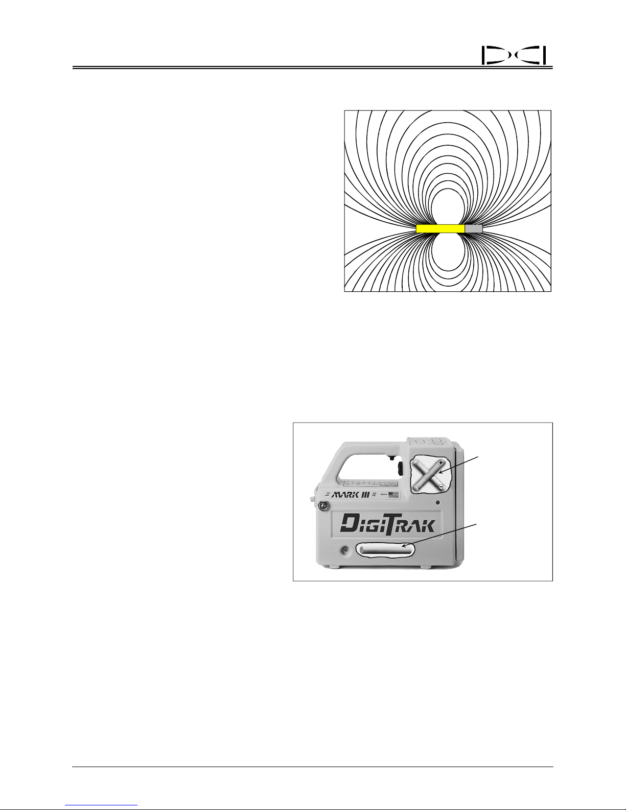
Locating
Transmitter’s Signal Shape
It is important to understand some fundamental concepts about the transmitter’s electromagnetic signal
and the way the receiver’s antennas read or receive
this signal. The shape of the transmitter’s signal field
is elliptical. This
the DigiTrak Receiver’s unique “X” antenna configuration results in locating the transmitter at three specific
locations, not just the strongest/highest signal.
The transmitter’s electromagnetic field is made up of
many “field
walking in this magnetic field and your receiver’s antennas are picking up signal from those field lines.
elliptically shaped field combined with
signal lines.” As you locate, you are
®
Elliptical Shape of Transmitter Signal Field
Antenna Configuration
The DigiTrak Receiver has a total of three antennas. The single antenna near the bottom of the unit
receives pitch, roll, battery, and temperature status from the transmitter. The “locating antennas” are
located below the display windows and are in an “X” configuration. One of the antennas is referred to as
the minus (“–”) antenna and the other as the plus (“+”) antenna. The antennas are positioned at right
angles to one another (perpendicular),
each 45° to the surface below the
DigiTrak Receiver. As described above,
the more “in-line” the field line is with the
antenna, the higher the percentage of
“read” signal.
Each antenna receives a different part of
the field
processed by the receiver to provide the
operator with a measurement of the
transmitter’s entire signal field strength—
not just a portion, as with conventional
cable locators.
signal. This information is
Location and Orientation of Antennas in Receiver
Depth / Locating
Antennas
/
Roll
Pitch
Antenna
Signal Reception
To understand how the antennas “read” these field lines, it is useful to imagine the field line as a stream
of water and the antenna as a pipe. If a stream of water is aligned parallel with the pipe, then 100% of
the water will flow through the pipe. If you turn the pipe 90° to the stream of water, no water will enter the
pipe. The same principle is true for the field line and the antenna; when they are parallel to one another
100% of the field line will be read by the antenna, and when they are perpendicular to one another none
(0%) of the signal will be read.
54 DigiTrak® Mark III Operator’s Manual
Page 63

®
Locating
Field Strength:
100%
0%
Field Strength:
Parallel Field Lines and Antenna Perpe
Orientation of Field Lines with Respect to Antennas
Front and Rear
Negative Locate Points
If the field line is vertical with respect to the antennas,
each antenna will read 50% of the signal (figure). This
occurs at two locations: one behind the transmitter,
known as the rear negative locate point (RNLP), and one
in front of the transmitter, known as the front negative
locate point (FNLP). Each of these locations is a specific
point that is independent of the transmitter’s signal
strength. Both the rear and front negative locate points
are important to accurately locating the transmitter, but
the FNLP is used more frequently. The FNLP is also
used to aid against oversteering.
Vertical Field Lines at FNLP and RNLP
0%
100%
ndicular Field Lines and Antenna
>>>>>>>>>>>>>>>
Field Strength:
>>>>>>>>>>>>>>>
50%
50%
>>>>>>>>>>>>>>>>>>>>>>>>>>>>>>>>>>>>
Field Strength:
Horizontal Field Lines at PLL
DigiTrak® Mark III Operator’s Manual 55
50%
50%
Positive Locate Line
Above Transmitter
When the field line is horizontal with respect to the
antennas, each antenna will read 50% of the field strength
at that point. This location is directly above the transmitter
and is referred to as the positive locate line (PLL). The
transmitter’s exact lateral location below the PLL can be
determined either by using the FNLP and RNLP or by
finding the peak signal. However, locating the transmitter’s position below ground using the peak signal is not
encouraged due to its susceptibility to interference
potentials.
Page 64

Locating
Notes
®
3-3000-00j-F
56 DigiTrak® Mark III Operator’s Manual
Page 65

®
DIGITAL CONTROL INCORPORATED
Cable Transmitter System
Power Supply
Extraction/Insertion Tool
DigiTrak Cable Transmitter System
The DigiTrak Cable Transmitter System is designe
¾
Borepaths with depths in excess of 50 ft (15 m).
¾
Borepaths with lengths that require several days to drill.
Remote Display
Cable
Transmitters
d specifically for the following applications:
¾
Borepaths that do not allow walkover locating.
¾
Borepaths in high-interference areas.
The depth and locating range of the
m), and it is approximately 100 ft (30 m) with a Mark I or Mark II Receiver. These depths are also dependent upon environmental conditions and characteristics of the housing. With the Cable Transmitter
System it is also possible to obtain pitch and roll information at any depth. Depth and lateral location information is tracked using the DigiTrak Receiver in exactly the same manner as with regular DigiTrak
Transmitters. The DigiTrak Receiver operator will not, however, obtain pitch, roll, or temperature information at the receiver because this information is sent directly to the remote display.
The Cable Transmitter System consists of four major components:
Cable Transmitter – This transmitter requires a special housing to accommodate the wire. The cable
transmitter i
the first butt splice connection. A compression fitting is required to seal the cable transmitter from drilling
fluid.
DigiTrak® Mark III Operator’s Manual 57
s inserted into the housing so that the cable extends through the back of the housing awaiting
cable transmitter with a Mark III Receiver is approximately 140 ft (43
Page 66

®
Cable Transmitter
Remote Display with Cable Transmitter Capability – This is a remote display that has been upgraded
or was originally built to display the cable transmitter data. During operation with a cable transmitter, a
delta symbol (Δ) illuminates in the top left window indicating the cable mode. All “cable-ready” remote
displays have a label near the battery compartment door that indicates it is configured to receive the
cable transmitter’s information (see photo). Not all remote displays have the Cable feature, but all can be
upgraded/modified for the cable transmitter function.
Label Indicating
Cable
-Ready Remote Display
Power Supply – This unit
wired directly to the cable transmitter. The power supply enables the information coming up the wire from
the cable transmitter to be displayed on the remote display and it sends power to the cable transmitter
from the above-ground batteries. It also contains a
circuit breaker to protect the system components.
Cable Extraction/Insertion Tool – This
used for inserting and extracting the cable transmitter to/from the housing. Two threaded holes
(1/4”-20 thread) are provided at the back of the
cable transmitter for threading the extraction tool.
Never remove the cable transmitter by pulling on
the wire.
Items such as compression fittings, 10-gauge
stran
ded copper wire, heat shrink, butt splices,
and slip-ring assemblies are not available from
DCI. Drill manufacturers will have information on
slip-ring assemblies, mud swivels, and compression fittings. Electrical supply houses will carry the
rest of the equipment needed for the Cable Transmitter System.
plugs into the remote display where the battery pack normally is inserted and is
tool is
58 DigiTrak® Mark III Operator’s Manual
Cable Transmitter Shown with Cable
Extraction/Insertion Tool Screwed into End
Page 67

®
Cable Transmitter
Power Supply
The Cable Transmitter Power Supply plugs into the remote display where a regular DCI battery pack is
normally placed. The power supply has three wires extending from it. The green and black wires should
be connected to a DC power source (green is positive, black is negative). The white wire is connected to
the cable transmitter (see sketch later in this section called “Connecting Cable Transmitter to Power
Supply and Remote Display”).
The power supply has the following features:
¾
There is an on/off button on the power supply that will disconnect power to the cable transmitter.
Power should be disconnected any time connections are made or broken. The red indicator light will
illuminate when power is supplied. To power up the Cable Transmitter System, it is necessary to turn
on both the remote display and the power supply.
Cable (w/ Green,
Power Supply
Black, and
White Wires)
Remote Display
On/Off Button
Cable Transmitter Power Supply Connected to Remote Display
The power supply controls and limits the power to the cable transmitter. In the event of a short circuit,
¾
power will be disconnected from the transmitter automatically. The power supply indicator light will go
out, and the transmitter will shut down. This condition can be corrected by eliminating the short
circuit. If the fault condition has been corrected, the power light will come back on automatically and
power will be restored to the transmitter.
The power supply requires an input voltage of 12V to 28V DC.
¾
¾
The power supply must be turned off at the end of the day to avoid overheating the cable transmitter.
NOTE: Do
ply. Run separate battery(ies) directly to the power supply, not through the auxiliary system on the drill.
The Cable Transmitter System can pick up electrical interference and noise introduced through the drill’s
power system.
DigiTrak
not use the drill’s power system as a source of power for the remote display and power sup-
®
Mark III Operator’s Manual 59
Page 68

®
Cable Transmitter
Cable Transmitter
The cable transmitter has the same general features and capabilities as the other DigiTrak Transmitters
but with increased depth range. The dimensions of the cable transmitter are the same as those of the 2cell DigiTrak Transmitters (DT, DX, and DXP). However, there is also a power/signal cable extending
from the rear metal grounding cap. The metal grounding cap must make solid contact with the interior of
the housing, which is grounded through the drill. The function of the wire is to provide power to the
transmitter and to send the pitch, roll, voltage, and temperature information to the remote display.
The cable transmitter is inserted into the transmitter
housing, using the cable extraction/insertion tool, so
that the cable extends through the back of the housing. A compression fitting is used to seal the
transmitter compartment from drilling fluid/water. Optimal compression fitting characteristics include a
washer in the uphole side of the rubber stopper (inside compression fitting) and/or a tapered-interiordiameter shaft to avoid stopper inverting due to drilling fluid pressure. The cable is routed through the
interior of the drill pipe; it exits the drill pipe at the drive chuck with another compression fitting or through
the mud swivel. As drill rods are added, the wires are connected using butt splices plus heat shrink with
hot melt glue. A slip-ring or mud-swivel assembly can be used to enable constant monitoring of the
transmitter information. These are not required; however, if one is not used, it will be necessary to
disconnect while drilling and reconnect the wires in order to view the transmitter information.
The Cable Transmitter System has the f
¾
The calibration procedure is a 1-point calibration; 2-point is required if the cable transmitter is in the
ollowing characteristics:
ground.
An input voltage between 12V and 28V DC.
¾
The typical power source is one or two 12V DC lead-acid automotive batteries, which may be
¾
connected in series for 24V DC. With this 24V DC source, approximately 2000 ft (610 m) can be
drilled before recharge.
White
+
12-Volt
Battery
Drill Rods
Black
Cable
–
Ground
Housing
Cable Transmitter
Drill Rig
Green
Power Supply
Connecting Cable Transmitter to Power Supply and Remote Display
60 DigiTrak® Mark III Operator’s Manual
Remote Display
Compression
Fitting
Cable
End Plug
Housing to Transmitter
Base is Negative
Contact for Grounding
Page 69

®
Cable Transmitter
¾ Temperature information can be accessed manually by turning off and then on the cable-ready
remote display.
¾
Upon supplying power, the cable transmitter will begin transmitting data.
¾
There is no sleep mode; therefore, the power supply must be turned off manually at the end of the
day. Failure to turn off the power overnight can result in an overheated cable transmitter.
¾
A low battery indication (BAT) could signify that another battery is needed.
¾
The remote steering feature may be used.
¾
The DataLog Mapping System may be used.
¾
An extraction/insertion tool is provided to remove and install the cable transmitter in the housing. The
cable transmitter’s wire must never be used to remove the transmitter.
¾
10-gauge stranded copper wire is suggested for use with the cable transmitter, as are butt splices
with hot melt glue heat shrink.
¾
A compression fitting is necessary behind the cable transmitter to seal drilling fluid from the
transmitter cavity.
Remote Display with Cable Transmitter Capability
The remote display used with the Cable Transmitter System has special components to accept pitch, roll,
voltage, and temperature information directly off the wire from a cable transmitter. (When tracking a
standard transmitter, the rece iver sends the pitch, roll, battery status, and temperature information to the
remote display using telemetry.)
The depth and left/right steering information, which is processed by the rec
display by telemetry. Therefore, the information on the remote display is a combination of information
received from the cable transmitter and from the receiver. The receiver must be set to the same channel
as the remote display.
A delta symbol or triangle in the top left window of the remote display indicates if it is operating in the
cabl
e transmitter mode. Temperature will be displayed in the top right window of the remote display
following a 4°C increase. To view the cable transmitter’s temperature at any time, simply turn the remote
display unit off and then on (do not turn off the power supply). The temperature will display in degrees
Celsius in the top right window for
2 seconds during start-up. (See “Temperature Overheat Warning” in the
Transmitter Section.)
–
The battery indicator (BAT) in the top left
wind
ow, which is normally used to signal
a low battery condition in the transmitter,
will now indicate the voltage of the
transmitter’s above-ground battery(ies).
When the BAT symbol appears, it is time
to add another battery to the power
–
+
12-Volt
Battery
system. Be sure batteries are added
correctly in series (see diagram).
eiver, is sent to the remote
24 Volts DC
–
12-Volt
Battery
+
+
®
DigiTrak
Mark III Operator’s Manual 61
Adding Batteries in Series
Page 70

®
Cable Transmitter
Viewing the Cable System Battery Status
The percentage of required voltage will be displayed in the top left window of the remote display for 2
seconds when the transmitter’s temperature increases by 4°C, which will be displayed in the top right
window. To manually access the voltage status, turn the remote display off and on and observe the top
left window after the firmware version is displayed. The voltage status is displayed in percent remaining
(above the minimal necessary voltage) and is based on a 28V DC power source. Therefore, 28V will
display as 100%, 19V as 50%, 12V as 25%, 9V as 0%.
When a standard DCI battery pack is installed into the remote display, rather than the Cable Transmitter
r Supply, it will automatically switch from the cable transmitter mode. Pitch, roll, temperature, and
Powe
battery status will again be received by telemetry from the DigiTrak Receiver.
Operation
The cable transmitter is located using the FNLP, RNLP, and PLL in the same manner as other DigiTrak
Transmitters, except the receiver will not display the transmitter’s pitch, roll, and battery or temperature
status—this information is displayed only on the remote display. Many cable bores do not allow walkover
locating; therefore, the depth of the transmitter is often calculated using the pitch information (see
“Running off Pitch or Calculating Depth from Pitch” in the Locating Section) or by using the real-time
DataLog System.
With the cable transmitter inside the housing/tool and grounded to the drill, com
procedure. Ensure that there are no metal objects between the tool and the receiver during calibration.
Check depth readings against a measuring tape at varying distances from the cable transmitter.
Calibration can be done with the housing tool installed on the drill rig. The pitch angle does not affect
calibration.
Note that, because the cable transmitter emits twice the si
DXP, D4X, D4XP), the receiver will be saturated with signal at distances closer than 60 inches (152 cm).
Therefore, it may not be possible to obtain a depth reading at distances less than 60 inches (152 cm). To
determine the maximum depth range of the cable transmitter, move the receiver away from the
transmitter until the depth becomes very unsteady or reads “1999”. Although the depth of the tool can be
calculated from the pitch information, it will not be possible to locate the tool by walking over it at depths
greater than the maximum range. The ability to locate the FNLP and RNLP is also dependent on the
maximum depth range.
Ensure that the remote display and power supply are con
the drill’s DC power supply.
A multimeter should be available for power testing/trouble
shooting the Cable Transmitter System, please contact Customer Service at 425-251-0559 or 800-288-
3610.
gnal strength of a long-range transmitter (DX,
nected directly to the power source, not through
shooting. For detailed instructions on trouble-
plete a 1-point calibration
3-3000-00k-F
62 DigiTrak® Mark III Operator’s Manual
Page 71

®
DIGITAL CONTROL INCORPORATED
Troubleshooting
Problem/Concern Causes/Solutions Section to Consult
1999 in bottom window of
receiver, indicating no signal
is being received from the
transmitter.
A number ranging from 200 to
700 in bottom window of
receiver and transmitter is not
active.
Depth suddenly decreases
18–24 inches (46–61 cm).
Depth after calibration
displays as 297–305 instead
of 119–121.
Incorrect depth. Interference.
Erratic information on
receiver.
Remote display has dashes
across windows.
Transmitter is asleep (wake it up by
rotating the drill string).
Dead batteries in the transmitter.
Broken transmitter.
Overheated transmitter.
Transmitter is out of range of receiver.
Receiver is receiving background noise.
Ultrasonics have not been zeroed and
receiver is being set on the ground for
depth reading. Due to the likelihood of
interference, do not measure with the
receiver on the ground.
Depth measurement mode in receiver has
been inadvertently changed from inches
(English) to centimeters (metric).
Ultrasonics improperly set.
Bad calibration.
Weak signal from the transmitter.
Receiver is not directly over transmitter
n taking a depth reading (trigger must
whe
be released).
Receiver malfunction.
Interference.
Low battery in receiver.
Moisture inside the equipment. Call DCI
for informatio
“drying” out the equipment. Moisture can
be caused by condensation which occurs
when the equipment is repetitively moved
to and from a warm environment and a
cold one.
Receiver is set on channel 0 (the telemetry
is off).
Receiver is set to a different channel than
remote dis
n about field methods for
play.
“Electrical Interference/
Backgroun
in Signal Interference
Section
Transmitter Section
“Electrical Interference/
Background Noise Check”
in Signal Interference
Section
“Ultrasonic Function” in
Receiver Section
“Changing the Depth
Measurement Units” in
Receiver Section
“Electrical Interference/
Backgroun
in Signal Interference
Section
“Ultrasonic Function” in
ceiver Section
Re
“Electrical Interference/
Backgroun
in Signal Interference
Section
Remote Display Section
“Changing the Receiver’s
Cha
Receiver Section
d Noise Check”
d Noise Check”
d Noise Check”
nnel Setting” in
DigiTrak® Mark III Operator’s Manual 63
Page 72

®
Troubleshooting
Problem/Concern Causes/Solutions Section to Consult
Remote display has dashes
across windows.
(Continued)
No pitch, roll, battery and
temperature information.
Rolling clock. Interference.
Can’t get the “+/–” signs to
give a “crisp” flip when
attempting to find the FNLP
or RNLP.
Interference is interrupting the signal from
the receiver.
Line of sight between receiver and remote
ay may be obstructed (by such things
displ
as buildings, hills, or dense vegetation).
Receiver is not equipped to send a signal
back to a rem
your receiver is “remote capable” observe
the back of the receiver. There must be a
large orange arrow for your receiver to be
able to send a signal to the remote display
at the drill.
Telemetry of receiver is not compatible
with telemetry of remote dis
the telemetry information located below the
serial number on the receiver and the
remote display; verify that they match.
If possible, substitute another receiver or
remote di
equipment is problematic.
Interference.
Receiver may be out of range of
transmitter. If possible try anothe
for comparison or a transmitter with a
stronger signal strength.
Receiver malfunction. If receiver is a Mark
III model, complete the self-test.
Verify squiggle (“~”) in top left window
flashe
distortion is present. Try another
transmitter to confirm problem.
Interference.
Receiver is not being held level and
steady.
As the transmitter’s depth increases, the
locate p
side and the right side of the drill string.
When this occurs the distance between
these two points is split to find the true
FNLP or RNLP.
splay to determine which piece of
s at regular intervals. If not, signal
oints may be found on both the left
ote display. To confirm that
play. Compare
r receiver
“Electrical Interference/
Backgroun
in Signal Interference
Section
Remote Display Section
“Electrical Interference/
Backgroun
in Signal Interference
Section
“Self-Test for Mark III
Re
ceivers” in Operational
Tests Section
“Electrical Interference/
Backgroun
in Signal Interference
Section
“Electrical Interference/
Backgroun
in Signal Interference
Section
Receiver Section
“Splitting of the Front and
Rea
Points” in Locating Section
d Noise Check”
d Noise Check”
d Noise Check”
d Noise Check”
r Negative Locate
64 DigiTrak® Mark III Operator’s Manual
Page 73

®
Troubleshooting
Problem/Concern Causes/Solutions Section to Consult
Erratic depth. Interference.
Transmitter is off.
If possible, try another receiver or
transmitter to identify the problem. The
approximate
using the pitch information and the
distance between the FNLP and RNLP.
Receiver or transmitter malfunction.
Transmitter exits further to
the left or right than receiver
indicated.
All windows are blank.
No squiggle (“~”) in top left
window.
100 or -100 in top left window
(with trigger released).
99 in top right window (with
trigger released).
Receiver was not held level when locating
transmitter.
Transmitter is being located by sweeping
receiver ove
instead of using the FNLP and RNLP.
Receiver’s antennas are out of balance.
The anten
performing a diagnostic procedure over the
phone with DCI customer service
personnel or by sending your receiver to
DCI for testing/repair.
Receiver has shut off to conserve battery
life. This occurs
received a signal for 15 minutes. Simply
click the button to turn the receiver on (all
calibration data will be preserved).
Receiver will automatically shut itself off if
the calib
before the receiver has completed its start-
up process.
If the receiver will not stay on, the battery
may be dead.
is fully charged.
Interference.
Receiver is out of range of transmitter.
Transmitter or receiver malfunction. If
possibl
transmitter.
Pitch sensor in transmitter has
malfunctioned. Replace transmitter.
Transmitter temperature sensor has
malfunctioned. Replace transmitter.
nas can be balanced by
ration procedure is attempted
e substitute a different receiver or
depth may be calculated
r it, looking for peak signal
when the receiver has not
Test the battery to see if it
“Electrical Interference/
Backgroun
in Signal Interference
Section
“Running Off Pitch or
Cal
culating Depth from
Pitch” in Locating Section
“Calculating Depth Based
on Di
FNLP & RNLP” in
Locating Section
Read Locating Section,
ch describes the
whi
DigiTrak method for
finding the transmitter
using the FNLP and
RNLP. The DigiTrak
provides better accuracy
using the locate points.
“1-Point Calibration
Procedu
Section
Battery Charger Section
“Electrical Interference/
Backgroun
in Signal Interference
Section
Transmitter Section
Transmitter Section
d Noise Check”
stance Between
re” in Receiver
d Noise Check”
DigiTrak® Mark III Operator’s Manual 65
Page 74

®
Troubleshooting
Problem/Concern Causes/Solutions Section to Consult
Minus sign (“–”) in bottom
window.
Roll positions sticking or not
accurate.
Not getting a solid depth
reading.
Bottom window depth/
distance flashes (with trigger
released).
Flashing squiggle (“~”) in
bottom window.
Solid squiggle (“~”) in bottom
window.
Receiver is set on ground for depth
reading, particularly at shallow depths, and
the ultrasonics are not reset. Reset the
ultrasonics.
Receiver has gone out of calibration.
Re
calibrate using either 1-point or 2-point
calibration.
Interference (squiggle in top left window
will not blink regularly).
If squiggle is blinking regularly, there may
be a tran
possible substitute a different receiver.
If you have a Mark III Receiver, conduct a
self-te
determination.
Transmitter has been overheated (temp
dot is bla
Interference.
The approximate depth may be calculated
usin
distance between the FNLP and RNLP.
Transmitter is being exposed to temperatures in excess of 60ºC (140ºF). Verify
that temp dot is not black before further
use of transmitter.
Transmitter has been exposed to tempera-
tures in excess of 60ºC (140ºF). Verify
that temp dot is not black before further
use of transmitter.
With 5.0 and later series firmware, the
receiver will display the transmitter’s
predicted depth at the FNLP in the bottom
window, along with a solidly illuminated
squiggle, when the trigger is held in. Pre-
5.0 series firmware will not do this.
smitter or receiver malfunction. If
st for error code and failure
ck).
g the pitch information along with the
“Ultrasonic Function” in
ceiver Section
Re
“Calibrating the Receiver”
in Receiver S
“Electrical Interference/
Backgroun
in Signal Interference
Section
“Self-Test for Mark III
Re
ceivers” in Operational
Tests Section
“Temperature Overheat” in
Tran
smitter Section
“Electrical Interference/
Backgroun
in Signal Interference
Section
“Running Off Pitch or
Cal
culating Depth from
Pitch” in Locating Section
“Calculating Depth Based
on Di
stance Between
FNLP & RNLP” in
Locating Section
Transmitter Section
Transmitter Section
“5.0 Series Firmware
Functions” in Receiver
Section
Locating Section
ection
d Noise Check”
d Noise Check”
66 DigiTrak® Mark III Operator’s Manual
Page 75

®
Troubleshooting
Problem/Concern Causes/Solutions Section to Consult
Ultrasonics don’t work.
Check ultrasonic holes on bottom of
receiver for m
carefully clean them out. Be extremely
careful not to puncture the metal inside the
ultrasonic holes. Use isopropyl alcohol
(99% by volume) in modest amounts;
swish around (upside down) and fling out
the liquid. Repeat two more times and
allow to dry for about 15 minutes.
If you still cannot get the ultrasonic
function to pe
customer service at 425-251-0559 or 800288-3610 for assistance.
ud or debris. If dirty,
rform properly, call DCI
“Ultrasonic Function” in
Re
ceiver Section
DigiTrak® Mark III Operator’s Manual 67
Page 76

Troubleshooting
Notes
®
3-3000-00l-F
68 DigiTrak® Mark III Operator’s Manual
Page 77

®
DIGITAL CONTROL INCORPORATED
Glossary
Active Transmitter
A transmitter that has batteries installed or a ca
Battery Charger
Used to charge and condition (discharge
and is easily adapted for worldwide usage.
Cable Transmitter
Transmitter that is hard wired directly to the remote d
during very long and/or deep drilling runs.
Clicking vs. Holding Trigger
See Trigger Clicked, Trigger In, and Trigger Out.
DataLog System
The logging function hardware and firmware used for collecting the data about the drilling operation to
uce plots of the borepath location.
prod
ble transmitter that is hooked up to power.
) the DigiTrak batteries. May be used with AC or DC sour ces
isplay unit and allows information to be obtained
Depth vs. Slant Distance vs. Range
Depth i
the transmitter (with the trigger released). Slant distance is the number in the bottom window when
the receiver is not positioned above the transmitter (with the trigger released). Range is the maximum
depth of a transmitter; it can be affected by interference from both above- and below-ground sources,
conductive soil, and salt water.
Drill Head or Tool
See Housing.
English Mode
The term used to describe depth measurements in inches.
Firmware
The software and hardware configuration programmed in the
facturer. The firmware is not accessible to the user and can only be upgraded by the manufacturer.
Four Turn Technique
An alternative method for finding the FNLP or the RNLP usi
Usually performed when the transmitter’s position is unknown. See “Four Turn Technique” in the
Locating Section.
Front Negative Locate Point (FNLP) = Locate Point in Front o f Transmitter
This location, used in conjunction with the positive locate line (a
negative locate point, provides the transmitter’s location information to the operator. For more information see the Locating Section.
s the number displayed in the bottom window when the receiver is positioned directly above
equipment as provided by the manu-
ng the plus/minus (“+/–”) indicators.
bove the transmitter) and the rear
Height-Above-Ground Distance = Ultrasonic Distance = Ultras onic Measurement
The height-above-ground or ultrasonic distance is used by th
of the transmitter. For more information see “Ultrasonic Function” in the Receiver Section.
DigiTrak® Mark III Operator’s Manual 69
e receiver to calculate the depth/distance
Page 78

Glossary
Housing = Drill Tool = Drill Head
The downhole device into which the transmitter fits.
Locate Line and Points
See Positive Locate Line, Front Negative Locate Point, and Rear Negative Locate Point.
Magnetic Distance
The magnetic distance is used by the receiver to calculate the d
more information see “Ultrasonic Function” in the Receiver Section.
Mark III
Designation used to delineate DigiTrak Receivers with an imp
Receivers. The Mark III has special shielding that increases the range of any DigiTrak Transmitter
and helps decrease the effects of some types of interference.
Mark III Self-Test
Procedure for completing a self-diagnostic test on
ultrasonic transducers (other ultrasonic components are tested). The self-test must be completed in
an interference-free area and out of range of any active transmitters. For more information see “SelfTest for Mark III Receivers” in the Operational Tests Section.
all the components of the receiver except the
epth/distance of the transmitter. For
roved design over the Mark I and Mark II
®
Metric Mode
The term used to describe depth mea
Pitch
The angle or inclination of the transmitter relative to the ho
divided by run). DCI transmitters can measure and display pitch in both 1% and 0.1% increments.
Positive Locate Line (PLL) = Line Above Transmitter
This location in conjunction with the FNLP and/or
low ground.
Predicted Depth
The predicted depth provides a prediction of the transmitter’
holds in the receiver’s trigger. The predicted depth is displayed in the bottom window as a flashing
number and a solidly lit squiggle (“~”) symbol. For more information see “5.0 Series Firmware Functions” in the Receiver Section and see the Locating Section.
Rear Negative Locate Point (RNLP) = Locate Point Behind Transmitter
This location is used in conjunction with the positive locate line
mitter’s lateral location and direction of movement. For more information see the Locating Section.
Receiver
Also referred to in the HDD industry as a locator, it is the po
receive the transmitter’s signals, process the signal information, and display the transmitter’s status to
the operator. The receiver may also be equipped with a telemetry transmitter to send information back
to a remote display at the drill rig.
surements in centimeters.
rizontal displayed in percent (%) slope (rise
that Runs Perpendicular to the Transmitter
RNLP determines the position of the transmitter be-
s depth at the FNLP when the operator
and the FNLP to provide the trans-
rtable device that is used above ground to
Reference Line
A predetermined line or set of surface characteristics g
(used for reference during drilling). Mainly used when mapping bores using the DataLog System.
70 DigiTrak® Mark III Operator’s Manual
enerally along the intended path of the bore
Page 79

®
Glossary
Remote Display
A device at or near the drill rig used to display the transmitte
receiver. This device can be used for remote steering when walkover locating is not possible.
Roll
The rotation about the longitudinal axis of the transmitter.
Set the Ultrasonics
To set the ultrasonics, click the trigger once and o
for 2 seconds will now be subtracted from the total magnetic distance. The ultrasonics can be set an
unlimited number of times without affecting the calibration. The ultrasonic measurement is used to
accommodate the different heights of drillers.
Slant Distance
See Depth vs. Slant Distance vs. Range.
Start-up = Power-up = Boot-up
This occurs when a battery is placed in the receiver or remote display and the unit is turned on. Power
on initiates a
the start-up sequence is complete.
start-up sequence of display information. Calibration or locating cannot be initiated until
bserve the bottom window. The number displayed
r’s information communicated from the
Start-up Sequence
The progression of receiver start-up displays that pro
the receiver, the depth measurement mode, the voltage of the receiver’s battery (if 5.07 firmware), the
channel the receiver will use to send signals to the remote display at the drill; and an LCD symbol test.
Telemetry
The signal by which the receiver communicates to the remote display. There is a telemetry transmitter
in the receive
Transmitter
The transmitter (also known in the industry as a sonde, beacon, or pro
tool and emits electromagnetic signals to aboveground surface that allow the locator to determine
position, orientation, and other parameters affecting the operation. The range of the transmitter is
variable and can be increased by using a Mark III Receiver.
Trigger Clicked
Clicking the trigger is pushing in and then releasing th
action will initiate an ultrasonic measurement. For more information see “Clicking vs. Holding the Trigger” and “Ultrasonic Function” in the Receiver Section.
Trigger In
When the trigger is held in, the system is in “locatin
able when the trigger is held in during normal locating as well as at start up. For more information see
“Clicking vs. Holding the Trigger” in the Receiver Section.
Trigger Out
When the trigger is out or released, the system is in “tr
distance/depth are displayed and continuously updated. The information displayed on the receiver
immediately after a held-in trigger is released is dependent upon the firmware installed in the receiver.
For more information see “Clicking vs. Holding the Trigger” in the Receiver Section.
r and a telemetry receiver in the remote display.
vide information such as the firmware version in
be) fits inside the housing/drill
e trigger in less than ½ second. Generally, this
g mode.” Different types of information are avail-
acking mode.” The transmitter’s pitch, roll, and
DigiTrak® Mark III Operator’s Manual 71
Page 80

Glossary
Ultrasonic Distance = Ultrasonic Measurement = Height-Above-Ground M easurement
The receiver’s height above the ground, which is displayed in the
the trigger is clicked. The ultrasonic measurement is used to accommodate the different heights of
drillers. For more information see “Ultrasonic Function” in the Receiver Section.
Ultrasonic Function
Determines the elevation the receiver is above a surface
this “ultrasonic distance” in the bottom window of the receiver for 2 seconds any time the trigger is
clicked (after the unit is powered up). The transmitter does not need to be active for operation of the
ultrasonic function.
Ultrasonic Transducers
Sensors located in the two openings on the bottom of the re
receiver or the ultrasonic distance.
V AC
Volts alternating current.
V DC
Volts direct current.
(up to a distance of 90 inches) and displays
bottom window for 2 seconds after
ceiver that measure the height of the
®
3-3000-00m-F
72 DigiTrak® Mark III Operator’s Manual
Page 81

®
DIGITAL CONTROL INCORPORATED
Appendix
The information and tables contained in this appendix provid
tion of the Transmitter. The following information is provided:
Depth Increase in Inches per 10-foot Rod
Percent of Grade to Degree Conversions (1% Pitch Transmitters)
Percent of Grade to Degree Conversions (0.1% Pitch Transmitters or Sensitive Pitch)
Degree to Percent of Grade Conversions (1% Pitch Transmitters)
Degree to Percent of Grade Conversions (0.1% Pitch Transmitters)
Calculating Depth Based on Distance Between FNLP and RNLP
e further assistance for confirming the posi-
DigiTrak® Mark III Operator’s Manual 73
Page 82

Appendix
Percent Depth Increase Percent Depth Increase
Depth Increase in Inches per 10-foot Rod
1
2
3
4
5
6
7
8
9
10
11
12
13
14
15
16
17
18
19
20
21
22
23
24
25
26
1
2
4
5
6
7
8
10
11
12
13
14
15
17
18
19
20
21
22
24
25
26
27
28
29
30
27
28
29
30
31
32
33
34
35
36
37
38
39
40
41
42
43
44
45
50
55
60
70
80
90
100
®
31
32
33
34
36
37
38
39
40
41
42
43
44
45
46
46
47
48
49
54
58
62
69
75
80
85
74 DigiTrak® Mark III Operator’s Manual
Page 83

®
Appendix
Percent of Grade to Degree Conversions
(1% Pitch Transmitters)
Percent Degree Percent Degree Percent Degree Percent Degree
1
2
3
4
5
6
7
8
9
10
11
12
13
14
15
16
17
18
19
20
21
22
23
24
25
0.6
1.1
1.7
2.3
2.9
3.4
4.0
4.6
5.1
5.7
6.3
6.8
7.4
8.0
8.5
9.1
9.6
10.2
10.8
11.3
11.9
12.4
13.0
13.5
14.0
26
27
28
29
30
31
32
33
34
35
36
37
38
39
40
41
42
43
44
45
46
47
48
49
50
14.6
15.1
15.6
16.2
16.7
17.2
17.7
18.3
18.8
19.3
19.8
20.3
20.8
21.3
21.8
22.3
22.8
23.3
23.7
24.2
24.7
25.2
25.6
26.1
26.6
51
52
53
54
55
56
57
58
59
60
61
62
63
64
65
66
67
68
69
70
71
72
73
74
75
27.0
27.5
27.9
28.4
28.8
29.2
29.7
30.1
30.5
31.0
31.4
31.8
32.2
32.6
33.0
33.4
33.8
34.2
34.6
35.0
35.4
35.8
36.1
36.5
36.9
76
77
78
79
80
81
82
83
84
85
86
87
88
89
90
91
92
93
94
95
96
97
98
99
100
37.2
37.6
38.0
38.3
38.7
39.0
39.4
39.7
40.0
40.4
40.7
41.0
41.3
41.7
42.0
42.3
42.6
42.9
43.2
43.5
43.8
44.1
44.4
44.7
45.0
DigiTrak® Mark III Operator’s Manual 75
Page 84

Appendix
Percent of Grade to Degree Conversions
(0.1% Pitch Transmitters or Sensitive Pitch)
Percent Degree Percent Degree Percent Degree Percent Degree
0.1
0.2
0.3
0.4
0.5
0.6
0.7
0.8
0.9
1
1.1
1.2
1.3
1.4
1.5
1.6
1.7
1.8
1.9
2
2.1
2.2
2.3
2.4
2.5
0.1
0.1
0.2
0.2
0.3
0.3
0.4
0.5
0.5
0.6
0.6
0.7
0.7
0.8
0.9
0.9
1.0
1.0
1.1
1.1
1.2
1.3
1.3
1.4
1.4
2.6
2.7
2.8
2.9
3
3.1
3.2
3.3
3.4
3.5
3.6
3.7
3.8
3.9
4
4.1
4.2
4.3
4.4
4.5
4.6
4.7
4.8
4.9
5
1.5
1.5
1.6
1.7
1.7
1.8
1.8
1.9
1.9
2.0
2.1
2.1
2.2
2.2
2.3
2.3
2.4
2.5
2.5
2.6
2.6
2.7
2.7
2.8
2.9
5.1
5.2
5.3
5.4
5.5
5.6
5.7
5.8
5.9
6
6.1
6.2
6.3
6.4
6.5
6.6
6.7
6.8
6.9
7
7.1
7.2
7.3
7.4
7.5
2.9
3.0
3.0
3.1
3.1
3.2
3.3
3.3
3.4
3.4
3.5
3.5
3.6
3.7
3.7
3.8
3.8
3.9
3.9
4.0
4.1
4.1
4.2
4.2
4.3
7.6
7.7
7.8
7.9
8
8.1
8.2
8.3
8.4
8.5
8.6
8.7
8.8
8.9
9
9.1
9.2
9.3
9.4
9.5
9.6
9.7
9.8
9.9
10
®
4.3
4.4
4.5
4.5
4.6
4.6
4.7
4.7
4.8
4.9
4.9
5.0
5.0
5.1
5.1
5.2
5.3
5.3
5.4
5.4
5.5
5.5
5.6
5.7
5.7
76 DigiTrak® Mark III Operator’s Manual
Page 85

®
Appendix
Degree to Percent of Grade Conversions
(1% Pitch Transmitters)
Degrees Percent
0
1
2
3
4
5
6
7
8
9
10
11
12
13
14
15
16
17
18
19
20
21
22
0.0
1.7
3.5
5.2
7.0
8.7
10.5
12.3
14.1
15.8
17.6
19.4
21.3
23.1
24.9
26.8
28.7
30.6
32.5
34.4
36.4
38.4
40.4
Degrees Percent
23
24
25
26
27
28
29
30
31
32
33
34
35
36
37
38
39
40
41
42
43
44
45
42.4
44.5
46.6
48.8
51.0
53.2
55.4
57.7
60.1
62.5
64.9
67.5
70.0
72.7
75.4
78.1
81.0
83.9
86.9
90.0
93.3
96.6
100.0
DigiTrak® Mark III Operator’s Manual 77
Page 86

Appendix
®
Degree to Percent of Grade Conversions
(0.1% Pitch Transmitters)
Degrees Percent
0.1
0.2
0.3
0.4
0.5
0.6
0.7
0.8
0.9
1
1.1
1.2
1.3
1.4
1.5
1.6
1.7
1.8
1.9
2
2.1
2.2
2.3
2.4
2.5
2.6
2.7
2.8
2.9
3
0.2
0.3
0.5
0.7
0.9
1.0
1.2
1.4
1.6
1.7
1.9
2.1
2.3
2.4
2.6
2.8
3.0
3.1
3.3
3.5
3.7
3.8
4.0
4.2
4.4
4.5
4.7
4.9
5.1
5.2
Degrees Percent
3.1
3.2
3.3
3.4
3.5
3.6
3.7
3.8
3.9
4
4.1
4.2
4.3
4.4
4.5
4.6
4.7
4.8
4.9
5
5.1
5.2
5.3
5.4
5.5
5.6
5.7
5.4
5.6
5.8
5.9
6.1
6.3
6.5
6.6
6.8
7.0
7.2
7.3
7.5
7.7
7.9
8.0
8.2
8.4
8.6
8.7
8.9
9.1
9.3
9.5
9.6
9.8
10.0
78 DigiTrak® Mark III Operator’s Manual
Page 87

®
Appendix
Calculating Depth Based on
Distance Between FNLP and RNLP
It is possible to estimate the transmitter’s depth should the information displayed in the depth/distance
window become unreliable. This is only possible if the pitch and negative locate points are reliable and
the ground surface is level.
To estimate the transmitter’s depth, first measure th
pitch of the transmitter must also be reliably known. Using the Depth Estimation Table below, find the
divider that most closely corresponds to the transmitter’s pitch. Then use the following formula to estimate the depth:
Depth =
For example, if the transmitter’s pitch i
In this example, the distance between the FNLP and the RNLP is 11.5 ft (3.5 m). The depth would be:
Depth ==
s 34% then the corresponding divider value (from the table) is 1.50.
ft 11.5
1.50
7.66
e distance between the FNLP and the RNLP. The
RNLPandFNLPbetweenDistance
Divider
ft or approximately 7.7 ft (2.35 m)
Depth Estimation Table
Pitch Divider Pitch Divider Pitch Divider Pitch Divider
0 1.41 26 1.47 52 1.62 78 1.84
2 1.41 28 1.48 54 1.63 80 1.85
4 1.42 30 1.48 56 1.64 82 1.87
6 1.42 32 1.49 58 1.66 84 1.89
8 1.42 34 1.50 60 1.68 86 1.91
10 1.42 36 1.51 62 1.69 88 1.93
12 1.43 38 1.52 64 1.71 90 1.96
14 1.43 40 1.54 66 1.73 92 1.98
16 1.43 42 1.55 68 1.74 94 2.00
18 1.44 44 1.56 70 1.76 96 2.02
20 1.45 46 1.57 72 1.78 98 2.04
22 1.45 48 1.59 74 1.80 100 2.06
24 1.46 50 1.60 76 1.82
DigiTrak® Mark III Operator’s Manual 79
Page 88

Appendix
Notes
®
3-3000-00n-F
80 DigiTrak® Mark III Operator’s Manual
Page 89

®
DIGITAL
CONTROL
INCORPORATED
19625 62nd Ave. S., Suite B-103 y Kent, Washington 98032 USA y 425-251-0559 or 800-288-3610 y Fax 253-395-2800
www.digitrak.com (Web Site) DCI@digital-control.com (E-mail)
REMOTE TELEMETRY LICENSE
The attached license is required by the United States Federal
Communications Commission (“FCC”) for operation of the
®
DigiTrak
Remote Receiver. DigiTrak® Remote Receivers are identified by the orange arrow and the FCC ID #KKG007 on the label
below the battery compartment door.
This license was approved by the FCC under an overall license
®
issued to Digital Control Incorporated. An operator of a DigiTrak
Remote Receiver in the United States is no longer required to
apply for a separate personal license as previously required.
®
This license authorizes operation of the DigiTrak
®
ceiver in the United States only. The DigiTrak
Remote Receiver
Remote Re-
shall only be operated in accordance with the rules and regulations of the FCC and as outlined in the owner’s manual accompanying this equipment. No modifications may be made to the
®
DigiTrak
Remote Receiver or other DigiTrak® equipment.
It is the operator’s responsibility to obtain proper licensing for
®
operation of the DigiTrak
Remote Receiver outside of the United
States.
Page 1 of 2
Page 90

3-3000-00o-F Page 2 of 2
Page 91

®
DIGITAL
CONTROL
INCORPORATED
19625 62nd Ave. S., Suite B-103 y Kent, Washington 98032 USA y 425-251-0559 or 800-288-3610 y Fax 253-395-2800
www.digitrak.com (Web Site) DCI@digital-control.com (E-mail)
LIMITED WARRANTY
Digital Control Incorporated ("DCI") warrants that when shipped from DCI each DCI product (“DCI Product”) will
conform to DCI’s current published specifications in existence at the time of shipment and will be free, for the
warranty period (“Warranty Period”) described below, from defects in materials and workmanship. The limited
warranty described herein (“Limited Warranty”) is not transferable, shall extend only to the first end-user (“User”)
purchasing the DCI Product from either DCI or a dealer expressly authorized by DCI to sell DCI Products
(“Authorized DCI Dealer”), and is subject to the following terms, conditions and limitations:
1. A Warranty Period of twelve (12) months shall apply to the following new
remote displays, battery chargers and rechargeable batteries, and DataLog
Period of ninety (90) days shall apply to all other new DCI Products, including transmitters, accessories, and
software programs and modules. Unless otherwise stated by DCI, a Warranty Period of ninety (90) days shall
apply to: (a) a used DCI Product sold either by DCI or by an Authorized DCI Dealer who has been expressly
authorized by DCI to sell such used DCI Product; and (b) services provided by DCI, including testing, servicing,
and repairing an out-of-warranty DCI Product. The Warranty Period shall begin from the later of: (i) the date of
shipment of the DCI Product from DCI, or (ii) the date of shipment (or other delivery) of the DCI Product from an
Authorized DCI Dealer to User.
2. DCI's sole obligation under this Limited Warranty shall be limit
DCI's option, a covered DCI Product that has been determined by DCI, after reasonable inspection, to be
defective during the foregoing Warranty Period. All warranty inspections, repairs and adjustments must be
performed either by DCI or by a warranty claim service authorized in writing by DCI. All warranty claims must
include proof of purchase, including proof of purchase date, identifying the DCI Product by serial number.
3. The Limited Warranty shall only be effective if: (i)
Product, User mails a fully-completed Warranty Registration Card to DCI; (ii) User makes a reasonable
inspection upon first receipt of the DCI Product and immediately notifies DCI of any apparent defect; and
(iii) User complies with all of the Warranty Claim Procedures described below.
ed to either repairing, replacing, or adjusting, at
within fourteen (14) days of receipt of the DCI
DCI Products: receivers/locators,
®
modules and interfaces. A Warranty
WHAT IS NOT COVERED
This Limited Warranty excludes all damage, including damage to any DCI Product, due to: failure to follow DCI’s
use
r’s manual and other DCI instructions; abuse; misuse; neglect; accident; fire; flood; Acts of God; improper
applications; connection to incorrect line voltages and improper power sources; use of incorrect fuses;
overheating; contact with high voltages or injurious substances; or other events beyond the control of DCI. This
Limited Warranty does not apply to any equipment not manufactured or supplied by DCI nor, if applicable, to any
damage or loss resulting from use of any DCI Product outside the designated country of use. By accepting a DCI
Product, User agrees to carefully evaluate the suitability of the DCI Product for User's intended use and to
thoroughly read and strictly follow all instructions supplied by DCI (including any updated DCI Product information
which may be obtained at the above DCI website). In no event shall this Limited Warranty cover any damage
arising during shipment of the DCI Product to or from DCI.
User agrees that the following will render the above Limited Warranty void:
with any serial number, identification, instructional, or sealing labels on the DCI Product, or (ii) any unauthorized
disassembly, repair or modification of the DCI Product. In no event shall DCI be responsible for the cost of or any
damage resulting from any changes, modifications, or repairs to the DCI Product not expressly authorized in
writing by DCI, and DCI shall not be responsible for the loss of or damage to the DCI Product or any other
equipment while in the possession of any service agency not authorized by DCI.
(i) alteration, removal or tampering
Page 1 of 2
Page 92

DCI reserves the right to make changes in design and improvements upon DCI Products from time to time, and
User understands that DCI shall have no obligation to upgrade any previously manufactured DCI Product to
include any such changes.
The foregoing Limited Warranty is DCI’s sole warranty and is m
implied, including but not limited to the implied warranties of merchantability and fitness for a particular purpose
and any implied warranty arising from course of performance, course of dealing, or usage of trade. If DCI has
substantially complied with the warranty claim procedures described below, such procedures shall constitute
User’s sole and exclusive remedy for breach of the Limited Warranty.
In no event shall DCI be liable for any indirect, special, incidental, or consequential damages or for any
cov
er, loss of information, profit, revenue or use based upon any claim by User for breach of warranty,
breach of contract, negligence, strict liability, or any other legal theory. In no event shall DCI’s liability
exceed the amount User has paid for the DCI Product. To the extent that any applicable law does not
allow the exclusion or limitation of incidental, consequential or similar damages, the foregoing limitations
regarding such damages shall not apply
This Limited Warranty gives you specific legal rights, and you
state. This Limited Warranty shall be governed by the laws of the State of Washington.
.
ade in place of all other warranties, express or
may also have other rights which vary from state to
WARRANTY CLAIM PROCEDURES
1. If you are having problems with your DCI Product, you must first contact the Authorized DCI Dealer where it
was purchased. If you are unable to resolve the problem through your Authorized DCI Dealer, contact DCI’s
Customer Service Department in Kent, Washington, USA at the above telephone number between 6:00 a.m. and
6:00 p.m. Pacific Time and ask to speak with a customer service representative. (The above “800” number is
available for use only in the USA and Canada.) Prior to returning any DCI Product to DCI for service, you
obtain a Return Merchandise Authorization (RMA) number. Failure to obtain a RMA may result in delays or return
to you of the DCI Product without repair.
must
2. After contacting a DCI customer service representative by telephon
you in troubleshooting while you are using the DCI Product during actual field operations. Please have all related
equipment available together with a list of all DCI Product serial numbers. It is important that field troubleshooting
be conducted because many problems do not result from a defective DCI Product, but instead are due to either
operational errors or adverse conditions occurring in the User’s drilling environment.
3. If a DCI Product problem is confirmed as a result of fiel
service representative, the representative will issue a RMA number authorizing the return of the DCI Product and
will provide shipping directions. You will be responsible for all shipping costs, including any insurance. If, after
receiving the DCI Product and performing diagnostic testing, DCI determines the problem is covered by the
Limited Warranty, required repairs and/or adjustments will be made, and a properly functioning DCI Product will
be promptly shipped to you. If the problem is not covered by the Limited Warranty, you will be informed of the
reason and be provided an estimate of repair costs. If you authorize DCI to service or repair the DCI Product, the
work will be promptly performed and the DCI Product will be shipped to you. You will be billed for any costs for
testing, repairs and adjustments not covered by the Limited Warranty and for shipping costs. In most cases,
repairs are accomplished within 1 to 2 weeks.
4. DCI has a limited supply of loaner equip
available, DCI will attempt to ship loaner equipment to you by overnight delivery for your use while your
equipment is being serviced by DCI. DCI will make reasonable efforts to minimize your downtime on warranty
claims, limited by circumstances not within DCI’s control. If DCI provides you loaner equipment, your equipment
must be received by DCI no later than the second business day after your receipt of loaner equipment. You must
return the loaner equipment by overnight delivery for receipt by DCI no later than the second business day after
your receipt of the repaired DCI Product. Any failure to meet these deadlines will result in a rental charge for use
of the loaner equipment for each extra day the return of the loaner equipment to DCI is delayed.
ment available. If loaner equipment is required by you and is
d troubleshooting discussions with a DCI customer
e, the representative will attempt to assist
3-3000-00p-F Page 2 of 2
 Loading...