

• (D
)C
• (D
)C
03
• (D
)C
06
• (D
)C
06
• (D
)C
C
s
CO
SSO
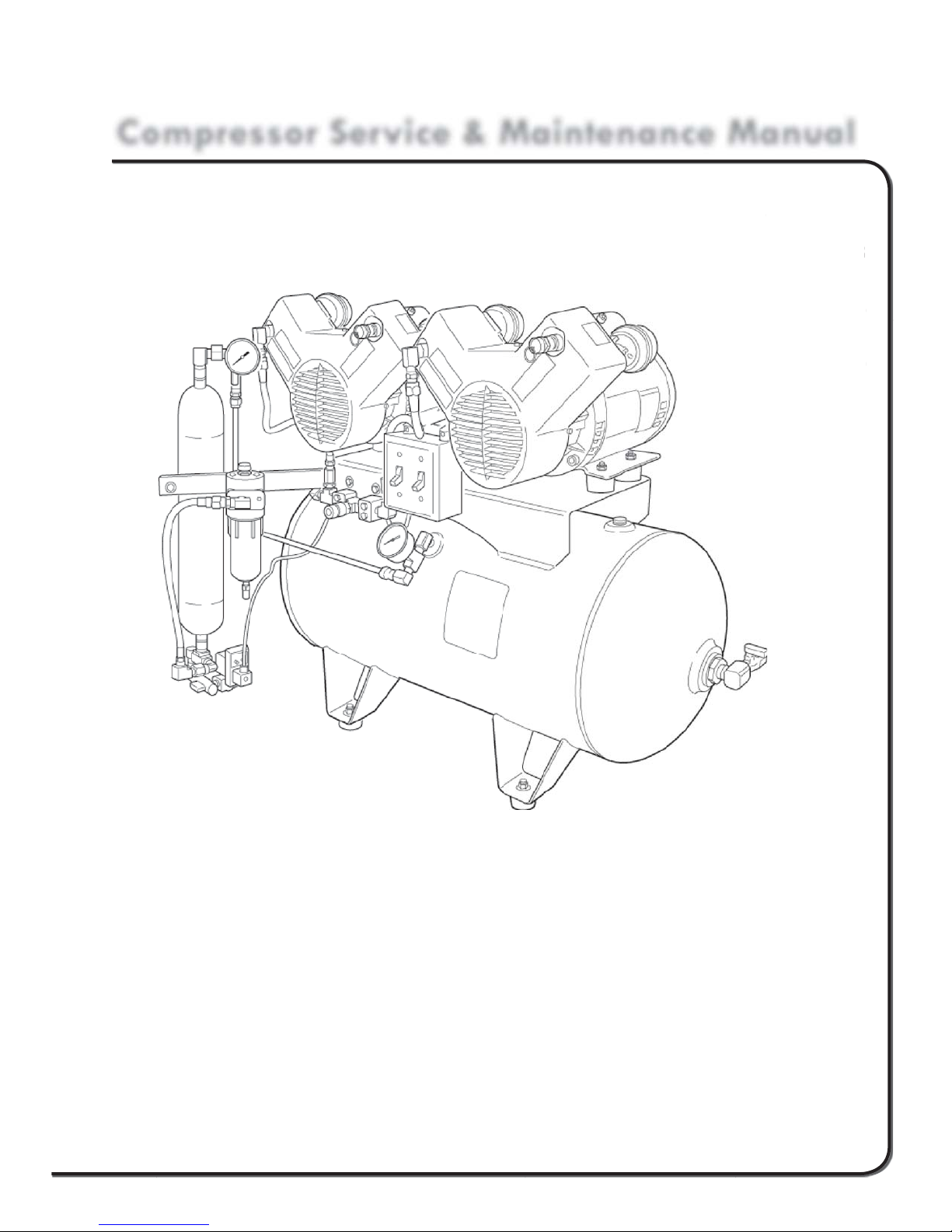
Compressor Service & Maintenance Manual
C Series
COMPRESSOR
MPRE
erie
R
• (D)C1103
• (D)C1203
• (D)C2106
• (D)C2206
• (D)C3210
1103
12
21
22
32
Copyright © 2006 DCI. All Rights Reserved.
92311, Rev. C, 08/13

1 www.dcionline.com
www.dcionline.com

C1000 Series Service & Maintenance Manual
Compressor Service, Maintenance, and Parts Manual
Section I: INTRODUCTION
A. General Specifications
Section II: THEORY OF OPERATION
A. While Running
B. Theory of Operation While Not Running
Introduction
SECTION I
Section III: MAINTENANCE
A. Compressor Head Intake Filter
B. Coalescing Filter
C. Time Operated Purge Valve
D. Tank Drain
Section IV SERVICE REPAIR INSTRUCTIONS
A. Troubleshooting Chart
B. Electrical
1. Replacing Pressure Switch
2. Replacing Power Switch
3. Replacing Compressor Head
4. Replacing Time Operated Purge Valve
C. Pneumatic
1. Replacing Check Valve
2. Replacing Differential Filter Indicator
3. Replacing Automatic Filter Float Drain
4. Replacing Desiccant Chamber
Section V ILLUSTRATED PARTS BREAKDOWN
A. Parts Listing
B. Electrical Schematic
C. Plumbing Schematic
1.800.624.2793
1
SECTION I
Introduction
C1000 Series Service & Maintenance Manual
Introduction
This manual contains the necessary information to perform all “fi eld serviceable” aspects of the DCI Oil-less Air Compressor line.
Please take the time to read this manual and understand the proper operation and service procedures before attempting to service
this machine. Our unique dryer purge system operates much differently than conventional air compressors. Understanding the
proper operation and design will ensure years of dependable operation.
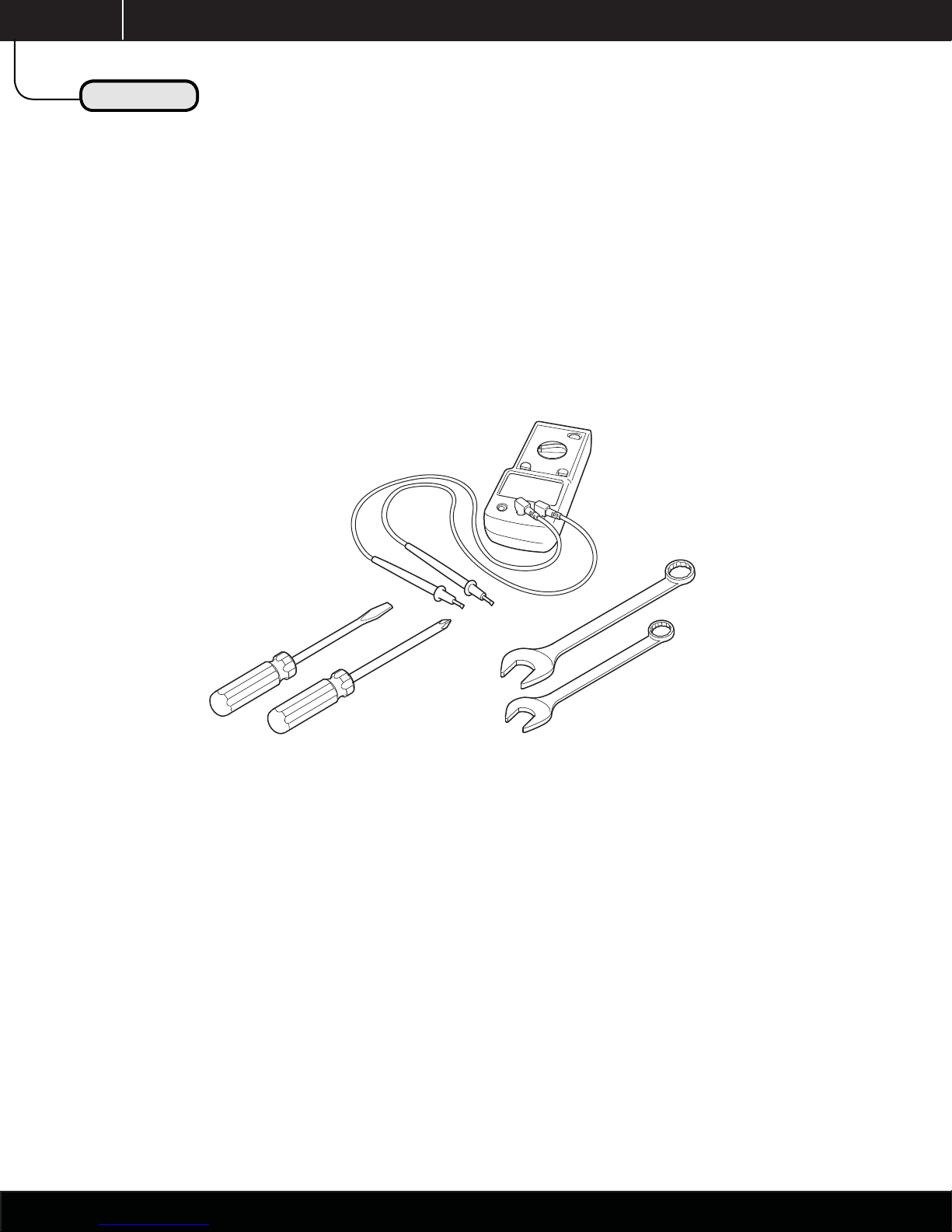
Below is a listing of the basic tools required to properly service this equipment.
Voltmeter
Screwdrivers:
Blade
Phillips
Combination
Wrenches
If you have any questions or need assistance in regards to any aspect ot the service and / or repair of this machine, please contact
the DCI Technical Support Department at:
Technical Support
1-800-624-2793
2
www.dcionline.com

C1000 Series Service & Maintenance Manual
Introduction
Introduction
INTRODUCTION
This manual contains the necessary instructions for the maintenance and/or service of the DCI air compressors.
There are 3 basic confi gurations available; single and dual head available in 115V and 230V, and the triple head available in 230V.
NOTE: ALL VOLTAGES +/- 5%
Confi gurations
1. Single 1 horsepower compressor head on 20 gal. Horizontal tank. (See Fig. A)
2. Dual 1 horsepower compressor heads on 20 gal. Horizontal tank. (See Fig. B)
3. Dual 1 horsepower heads on 30 gal. horizontal tank. (Not Shown)
SECTION I
Fig. A Fig. B
Picture of Single
Horizontal Compressor
Model #C1103 & #C1203
Picture of Dual
Horizontal Compressor
Model # C2106 & #C2206
Picture of Triple
Horizontal Compressor
Model # C3210
1.800.624.2793
3
g
3
SECTION I
Unpackin
Model Specifi cations
C1000 Series Service & Maintenance Manual
Introduction
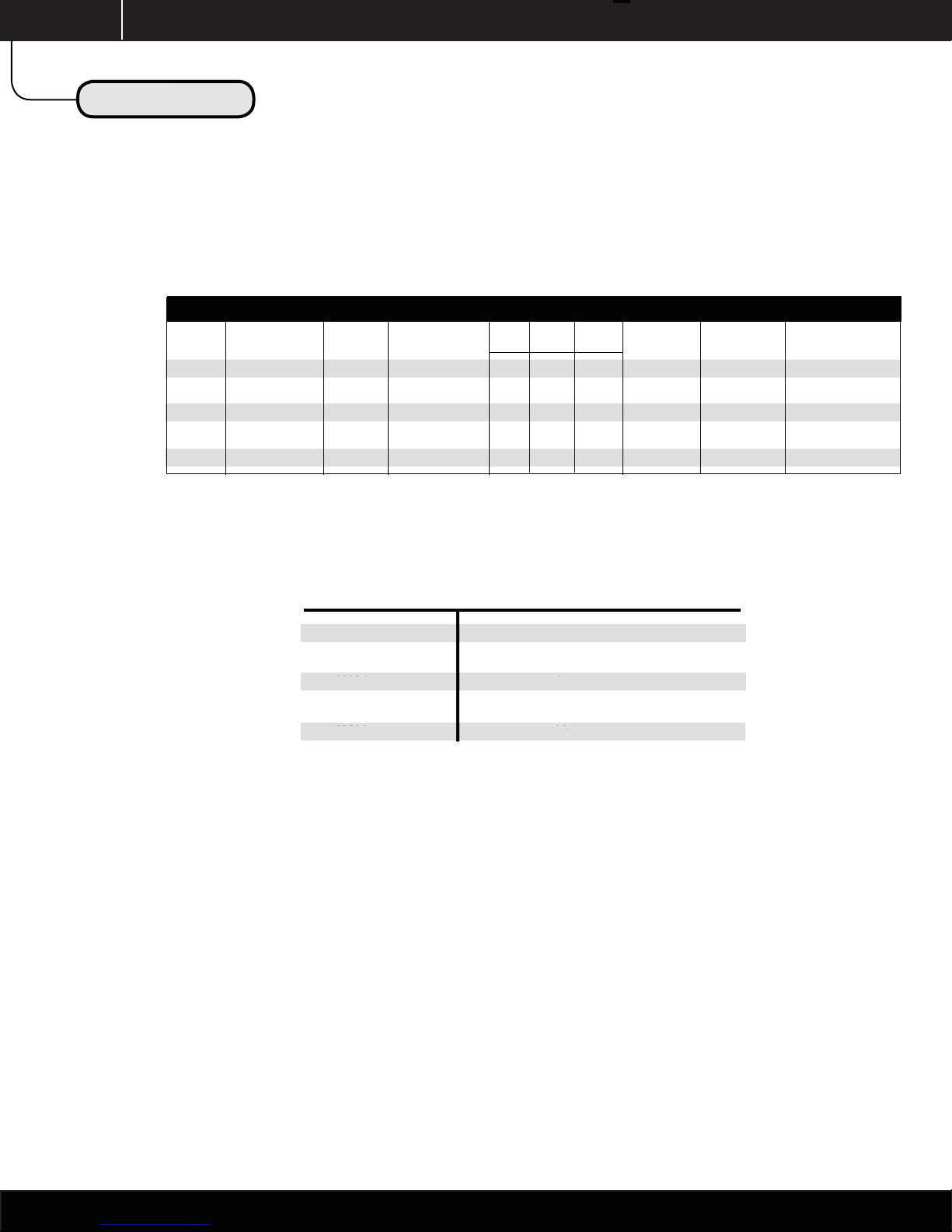
MODEL SPECIFICATIONS
Model CFM @ 80PSI Total HP Tank Capacity Dimensions (inches) Voltage Amps Circuit Breaker
L D H
C1103 3.95 1 20 34 24 29.5 115 13.4 15
C1203 3.95 1 20 34 24 29.5 230 6.7 10
C2106 7.95 2 20 34 24 29.5 115 26.8 30
C2206 7.95 2 20 34 24 29.5 230 13.4 15
C3210 11.85 3 30 46 26 36 230 21.1 30
NOTE: ALL VOLTAGES ARE +/- 5%
MODEL NUMBER MAXIMUM SIMULTANEOUS USERS
C1103 3
1103
C1203 3
C2106 6
C2206 6
C3210 10
NOTE: Number of users based on 1.5cfm @ 80psi per user. Additional equipment such as air abrasion units, blow-guns, and lab equipment should
be factored into the system requirements.
Site Requirement Templates and additional technical information available through our Technical Service Department.
4
1 www.dcionline.com
www.dcionline.com

C1000 Series Service & Maintenance Manual
Theory of Operation
Theory of Operation
THEORY OF OPERATION
While Running
To start the compressor, the user shall activate the compressor head or heads with the power switches located on the front center
of the machine. The selected motors will then begin to run and build pressure in the tank and piping system.
A. The air is taken in through the intake fi lters, located on the rear of each compressor cylinder. The dirt and dust is fi ltered out
of the intake fi lter to 5 microns in this process.
SECTION II
B. The air is then compressed with the pistons in each cylinder, and then travels through the after-cooler (copper) tubing, which
cools the air to help condense any moisture “humidity” taken in during the process of compression.
C. The wet / dirty compressed air and condensed moisture then travel through a coalescing fi lter assembly. This fi lter allows the
condensed moisture to fall to the bottom of the fi lter bowl via gravity, where it will be automatically expelled via the fl oat
drain contained in the bottom of the fi lter bowl. The compressed air also travels through the coalescing fi lter element, which
removes 99.998% of all particles down to 0.01 microns. A fi lter change indicator located on the top of the fi lter housing
shows the condition of the element, and alerts the operator as to when the element is in need of replacement. GREEN
indicates the element has more useful life, while RED indicates the element is in need of replacement.
NOTE: The indicator only functions while compressed air is traveling through the fi lter with compressor running. The indicator
will ALWAYS read “GREEN” with compressors not running.
D. The compressed air then travels through the bottom of the desiccant “drying chamber”, where the remaining contained
moisture is reduced to a pressure dewpoint of -100°F, and then travels into the main storage tank for use in the dental
operatory.
E. When reaching its cut-off pressure of 100psi, the pressure switch will open and the compressor motors will stop.
NOTE: The time operated dryer purge valve DOES NOT open and purge when compressor stops, as it does on most competitive
brands. See Theory of Operation “While Not Running” for more information as to the proper operation of our purge valve.
1.800.624.2793
5

SECTION II
Theory of Operation
While Not Running
A. When the motors stop after reaching the cut-out pressure of 100psi, the user will have clean / dry air ready for use in
the dental operatory. The compressor will remain in this “idle” state until the tank pressure drops to 80 psi, at which time
the compressor motors will turn on and return the running mode of operation.
B. The “Time Operated” dryer purge valve operates on a time basis instead of a “single cycle” basis used on most other
types of dental air compressors. Two timers, “located on the front of the valve assembly”, control how often and the
duration of each purge cycle.
C1000 Series Service & Maintenance Manual
Theory of Oporation
THEORY OF OPERATION
NOTE: The compressor does not purge when the
compressor cycles off!
C. The “Left” timer knob on the purge valve, controls the
duration of the purge cycles. This timer is factory preset
and should not be adjusted. The factory setting is at the
maximum of 10 seconds.
D. The “Right” timer knob on the purge valve controls how
often the compressor purges moisture from the drying
chamber. The factory setting is 7 minutes, and should NOT
be adjusted.
E. A “TEST” button is located between the two timer knobs
to allow a technician to verify that the valve is operating
correctly.
By purging the drying chamber on a time basis, the DCI air
compressors ensure the drying chamber desiccant remains dry,
even during heavy usages, for consistent air quality.
Aftercooling
Tubing
Coalescing
Filter
Condensate
Drain
Left
Motor
Check
Valve
Flow/Check
Drying Chamber
Strainer
Shutoff
Valve
Right
Motor
Check
Valve
Dryer Bypass
Ball Valve
Drying System
Pressure Gauge
To
Storage
Tank
6
1 www.dcionline.com
Time Purge
Valve
Plumbing Schematic
www.dcionline.com

While Not Running
Electrical Schematic
C1000 Series Service & Maintenance Manual
THEORY OF OPERATION
Theory of Oporation
SECTION II
Theory of Operation
1.800.624.2793
7

g
SECTION III
Unpackin
Maintenance
COMPRESSOR MAINTENANCE SCHEDULE
Maintenance Item Frequency
Intake Filter Elements Every Six Months (semi-annually)
Coalescing Filter Element Every 90 Days
Time Operated Purge Valve Every 60 Days
Tank Drain Every 90 Days
A. Compressor Head Intake Filter Elements
Dirty intake fi lter elements reduce the amount of air the compressor can take in. This
reduces air output and increases the load of the motors. Every six months, remove
the intake fi lter cover as shown in (Fig. D), to check for excessive dirt or discoloration.
Replace with DCI Part Number 2012 if needed. The fi lters are located on the rear of each
compressor cylinder.
C1000 Series Service & Maintenance Manual
Maintenance
MAINTENANCE
B. Coalescing Filter Element
The coalescing fi lter element should be checked with the compressor motors running. If
the indicator located on the top of the fi lter housing remains GREEN, the fi lter element has
additional useful life. However, if the indicator turns RED, the element should be changed.
To change the element, fi rst turn off the compressor motor switches. Then turn off the
Dryer bypass valve as shown in (Fig. E). With dryer bypass valve in OFF position, press the
TEST button on the time operated purge valve to bleed pressure off of the drying system.
Depressurization of the drying system can be confi rmed by reading the drying system
pressure gauge located on top of the drying chamber.
WARNING: DO NOT ATTEMPT TO SERVICE WITH SYSTEM PRESSURIZED.
Unscrew the fi lter bowl by turning counter-clockwise. Lower the fi lter bowl to access the
fi lter element contained inside. The fi lter element is held in place with an O-ring and
internal ridges located in the bowl. Replace with DCI Part Number 2006, and reassemble
the fi lter bowl. Turn the dryer bypass valve to the ON position and check compressor for
proper operation by turning the power switches on.
Fig. D
OFF
ON
NOTE: A “popping” relief valve indicates a clogged coalesing element OR
the Dryer Bypass valve is closed.
8
1 www.dcionline.com
Fig. E
www.dcionline.com

C1000 Series Service & Maintenance Manual
g
Maintenance
Unpackin
Maintenance
SECTION III
MAINTENANCE
C. Time Operated Purge Valve
The time operated purge valve should be checked for proper operation every 60 days. To test, press the TEST button located between the
two timer adjustment knobs (see Fig. F). If air escapes from the valve, it is working properly. If no air is expelled, verify that the fi lter /
strainer valve is in the ON position “parallel with fl oor”. Check the fi lter screen inside the fi lter / strainer valve as shown in Fig. G. If the
strainer / shutoff valve is on and the screen is not clogged, replace the Time Operated Purge Valve with DCI part Number 2011 for 230 volt
models, or DCI Part number 2848 for 115 volt models.
Fig. F
D. Tank Drain
The tank drain “petcock” should be opened to check for moisture in the storage tank every 90 days. The tank drain is located at the bottom
right hand side of the storage tank. (See Fig. H) If no moisture is present, the drying system is working properly. If moisture is present, refer
to the Time Operated Purge Valve section above.
Fig. H
Fig. G
1.800.624.2793
9

”
”
g
SECTION IV
Unpackin
Troubleshooting Chart
SYMPTOMS CAUSES POSSIBLE REMEDY
C1000 Series Service & Maintenance Manual
Service and Repair
TROUBLESHOOTING CHART
Compressor Will Not Run
Compressor Will Not Start, “hums”
ompressor Will Not Start, “hums
Motor Overheats
No Power
Improper Line Voltage
Tripped Overload
Pressure Switch
System Already at Pressure
Improper Line Voltage
Open Start Capacitor
Open Start Winding
Improper Voltage
Ambient Temperature Too High
Too Many Starts Per Hour
Cycle Time Too Long
Check circuit breaker.
Ensure that supply voltage matches equipment ratings.
Check for loose wiring.
Check contact points and adjust or replace.
Bleed pressure from system to ensure proper starting.
Ensure supply voltage matches equipment ratings.
Replace Start Capacitor.
Replace Compressor Head.
Ensure supply voltage matches equipment ratings.
Improve ventilation; add a fan.
Check for air leaks and repair; add additional compressor.
Check for air leaks and repair; add additional compressor.
High System Pressure
igh System Pressure
Low System Pressure
Relief Valve “popping”
elief Valve “popping
Clogged Intake Filter
Pressure Switch
Pressure Switch
System Undersized
Clogged Coalescing Filter Element
Dryer Bypass Valve Is Closed
Faulty Relief Valve
Replace intake Filter.
Improperly set or defective pressure switch.
Improperly set or defective pressure switch.
Additional or larger compressor required.
Replace coalescing fi lter element.
Replace relief valve.
Open Valve.
1 www.dcionline.com
10
www.dcionline.com

C1000 Series Service & Maintenance Manual
M
s
g
Troubleshooting Chart
TROUBLESHOOTING CHART
SYMPTOMS CAUSES POSSIBLE REMEDY
Service and Repair
Unpackin
SECTION IV
Compressor Overheats
Moisture In Air Lines
oisture In Air Line
Clogged Air Intake Filter
Exhaust Valve
Too Much Run Time
Ambient Temperature Too High
Time Operated Purge Valve
Timers Incorrectly Set
Strainer Valve Off or Clogged
Coalescing Filter Auto-Drain
Desiccant Failure
Compressor Undersized
Faulty Dental Unit Diaphragm
Clean or replace intake fi lter element.
Clean & Replace valve-plate.
Air leaks; compressor too small to meet demand.
Add ventilation and \ or cooling to equipment room.
Clean or replace solenoid valve assembly.
Left Timer knob “duration of purge” set at 10 seconds.
Right Timer knob “purge interval” set at 7 minutes.
Clean strainer and ensure valve is on.
Clean or replace as needed.
Replace drying chamber assembly.
Additional or larger compressor to met demand requirements.
Check Master shut-off and water relay diaphragms.
1.800.624.2793
11

SECTION IV
Electrical
A. Electrical Components
1. Pressure Switch: Turns on or off the power supplied to the
individual compressor motor switches. The pressure switch is preset
to run the compressors to 100psi and then open, therefore stopping
the motor(s). When the system pressure drops to 80psi, the switch
closes, running the compressor motors to 100psi again.
To test the switch, bleed all pressure from the tank. Remove the
pressure switch top cover with a 3/8” wrench. With an AC voltmeter,
place the test leads on the outer terminals as shown in Fig. I. The
voltage indicated should agree with the machine data plate, either 115
or 230 volt AC. If no voltage is present, check the circuit breaker.
C1000 Series Service & Maintenance Manual
Service and Repair
ELECTRICAL
Fig. I
If the proper voltage is present on the outer terminals, move the voltmeter test leads to the inner terminals of the pressure switch as shown in
Fig. J. If NO voltage is present, the pressure switch is defective. If voltage is present, proceed to the next step.
Turn the machine power on, and wait for compressor to reach 100psi
and stop running. The 3/8” adjusting screw may be turned clockwise
to increase the cutoff pressure or counter-clockwise to decrease the
cutoff pressure. The maximum pressure cutoff should not exceed
100psi. If the compressor will not cut off at the desired preset
pressure, or will not stop under any condition, the pressure switch is
defective.
12
1 www.dcionline.com
Fig. J
www.dcionline.com

2. Power Switches: The toggle switches located on the front center of the
compressor control the individual compressor motors. If the pressure
switch is operating correctly, remove the motor terminal cover on the back
of the desired compressor motor. With the power switch in the on “up”
position, check for voltage to the compressor motor as shown in Fig. K. If
the proper voltage is present, the power switch is good. If no voltage is
present at the motor, replace the corresponding power switch.
C1000 Series Service & Maintenance Manual
Service and Repair
Electrical
SECTION IV
Fig.K
3. Compressor Motor (head): The compressor motor turns the compressor crankshaft to generate airfl ow to the system. If the correct
voltage is present on the L1 and L2 terminals as described in the testing procedure listed above, but the compressor hums and does not
start, the start capacitor is defective. If the correct voltage is present but nothing happens, the head is defective.
To replace the motor, it is not required to cut the spade terminals from the wiring (see Figures L and M) for proper disassembly without
cutting factory wiring.
After removing the wiring from the compressor motor, the motor may be removed by unscrewing the air discharge hose on the front left
cylinder, and removing the four ½” nuts securing the head to the vibration isolation mounts.
Fig. L Fig. M
1.800.624.2793
13

SECTION IV
Electrical
To Replace the Time Operated Purge Valve
1. Remove the Philips head screw that holds the electrical connector in place, and pull the electrical connector off of the timer assembly.
2. Turn “OFF” the strainer / shutoff valve in Fig. N.
3. Remove the valve and replace with DCI Part Number 2011 for 230 volt machines OR DCI Part Number 2848 for 115 volt models.
C1000 Series Service & Maintenance Manual
Service and Repair
Time Operated Purge Valve
4. Return the strainer / shutoff valve to the On position.
NOTE: Make sure the coil voltage matches that of the machine data tag.
14
1 www.dcionline.com
Fig. N
www.dcionline.com

C1000 Series Service & Maintenance Manual
Service and Repair
SECTION IV
Electrical
PNEUMATIC
WARNING: HIGH SYSTEM PRESSURES MAY CAUSE SERIOUS INJURY.
ALWAYS DEPRESSURIZE THE ENTIRE SYSTEM BEFORE ATTEMPTING TO SERVICE PNEUMATIC COMPONENTS.
1. Replacing the check valves. If a check valve failure occurs, the symptom will be air escaping through one of the compressor
heads with the compressor NOT running. To replace a defective check valve, unscrew “counterclockwise” the air discharge hose fi tting
from the appropriate compressor head. Once the air discharge hose is disconnected from the compressor head, the check valve,
along with the discharge hose, may be removed from the discharge manifold by unscrewing the check valve ”counterclockwise”, and
replaced with a new check valve. Reverse this process to reassemble the check valve / discharge hose assembly.
2. Replacing the Differential Filter Indicator. If the differential indicator becomes stuck in either the red OR green
indicating position, the indicator needs replacement. Replace the differential fi lter indicator by unscrewing the entire assembly
“counterclockwise” with a 15/16” - 6 point / box end wrench. Install the new indicator in the reverse order.
3. Automatic Filter Float Drain. Unscrew the coalescing fi lter bowl from the fi lter head. Using a 9/16 wrench, unscrew the
retaining nut on the bottom of the fi lter bowl. With the retaining nut removed, the automatic fl oat drain will be removed from the
fi lter bowl. Replace in the reverse order.
4. Replacing Desiccant Chamber. To replace the desiccant chamber, remove the rigid stainless steel tubing from the dryer
bypass valve at the compression fi tting, located at the dryer bypass valve. Remove the top plumbing manifold assembly from the top
of the desiccant chamber, by turning counterclockwise. Remove the electrical cord from the dryer purge valve by removing the Philips
head retaining screw, and pulling the cable away from the valve timer block. Next, remove the fl exible discharge hose from the
discharge side of the coalescing fi lter, and then unscrew the bottom manifold assembly from the bottom of the desiccant chamber.
Replace the desiccant chamber and reassemble in the reverse order.
1.800.624.2793
15

g
SECTION V
Unpackin
Parts Call-Out
C1000 Series Service & Maintenance Manual
Illustrated Parts Breakdown
2856
Pressure Gauge
2005
Pressure
Switch
2013
Relief Valve
2012
Intake Element
2135
Check Valve
2014
Drying Chamber
Assembly
2002
1 hp Head
Data Tag
Outlet Ball Valve
2856
Pressure Gauge
2859
Petcock Valve
Bypass Valve
2009
Strainer Shut O
16
2008 Indicator
2135 Check Valve
2003 Coalescing Filter
2006 Coalescing Element
2007 Float Drain
2011 Automatic Purge Valve (230 Volt)
OR 2848 Automatic Puge Valve (115 Volt)
www.dcionline.com

C1000 Series Service & Maintenance Manual
g
Illustrated Parts Breakdown
Unpackin
Electrical Schematic
SECTION V
1.800.624.2793
17

SECTION V
g
Unpackin
Plumbing Schematic
C1000 Series Service & Maintenance Manual
Illustrated Parts Breakdown
Aftercooling
Tubing
Coalescing
Filter
Condensate
Drain
Left
Motor
Check
Valve
Flow/Check
Drying Chamber
Strainer
Shutoff
Valve
Right
Motor
Check
Valve
Dryer Bypass
Ball Valve
Drying System
Pressure Gauge
To
Storage
Tank
18
1 www.dcionline.com
Time Purge
Valve
www.dcionline.com

1.800.624.2793
19

305 N. Springbrook Road
Newberg, Oregon 97132 USA
503.538.8343
800.624.2793
www.dcionline.com
 Loading...