

DCI C1103, C2206, C1203, C2106, DC1103 Service Maintenance Manual
...
• (D
)C
• (D
)C
03
• (D
)C
06
• (D
)C
06
• (D
)C
C
s
CO
SSO
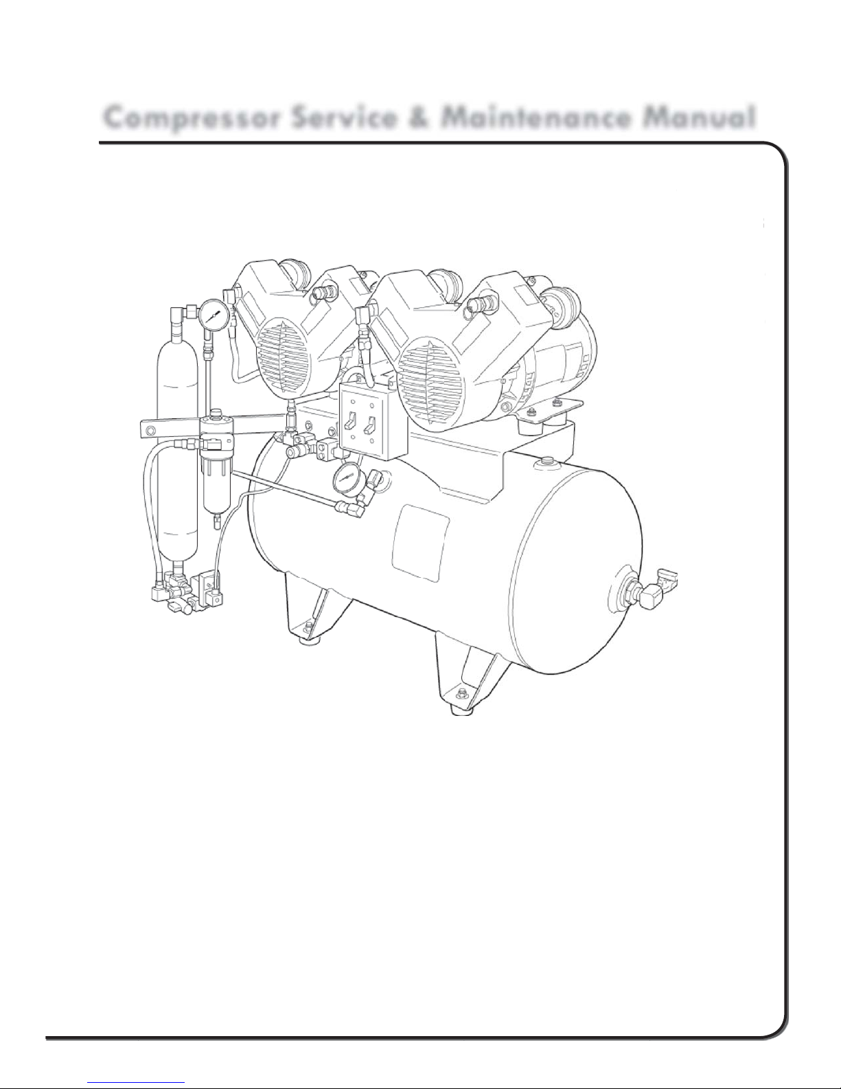
Compressor Service & Maintenance Manual
C Series
COMPRESSOR
MPRE
erie
R
• (D)C1103
• (D)C1203
• (D)C2106
• (D)C2206
• (D)C3210
1103
12
21
22
32
Copyright © 2006 DCI. All Rights Reserved.
92311, Rev. C, 08/13

1 www.dcionline.com
www.dcionline.com

C1000 Series Service & Maintenance Manual
Compressor Service, Maintenance, and Parts Manual
Section I: INTRODUCTION
A. General Specifications
Section II: THEORY OF OPERATION
A. While Running
B. Theory of Operation While Not Running
Introduction
SECTION I
Section III: MAINTENANCE
A. Compressor Head Intake Filter
B. Coalescing Filter
C. Time Operated Purge Valve
D. Tank Drain
Section IV SERVICE REPAIR INSTRUCTIONS
A. Troubleshooting Chart
B. Electrical
1. Replacing Pressure Switch
2. Replacing Power Switch
3. Replacing Compressor Head
4. Replacing Time Operated Purge Valve
C. Pneumatic
1. Replacing Check Valve
2. Replacing Differential Filter Indicator
3. Replacing Automatic Filter Float Drain
4. Replacing Desiccant Chamber
Section V ILLUSTRATED PARTS BREAKDOWN
A. Parts Listing
B. Electrical Schematic
C. Plumbing Schematic
1.800.624.2793
1
SECTION I
Introduction
C1000 Series Service & Maintenance Manual
Introduction
This manual contains the necessary information to perform all “fi eld serviceable” aspects of the DCI Oil-less Air Compressor line.
Please take the time to read this manual and understand the proper operation and service procedures before attempting to service
this machine. Our unique dryer purge system operates much differently than conventional air compressors. Understanding the
proper operation and design will ensure years of dependable operation.
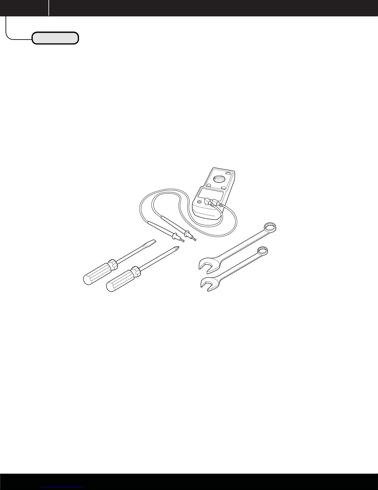
Below is a listing of the basic tools required to properly service this equipment.
Voltmeter
Screwdrivers:
Blade
Phillips
Combination
Wrenches
If you have any questions or need assistance in regards to any aspect ot the service and / or repair of this machine, please contact
the DCI Technical Support Department at:
Technical Support
1-800-624-2793
2
www.dcionline.com

C1000 Series Service & Maintenance Manual
Introduction
Introduction
INTRODUCTION
This manual contains the necessary instructions for the maintenance and/or service of the DCI air compressors.
There are 3 basic confi gurations available; single and dual head available in 115V and 230V, and the triple head available in 230V.
NOTE: ALL VOLTAGES +/- 5%
Confi gurations
1. Single 1 horsepower compressor head on 20 gal. Horizontal tank. (See Fig. A)
2. Dual 1 horsepower compressor heads on 20 gal. Horizontal tank. (See Fig. B)
3. Dual 1 horsepower heads on 30 gal. horizontal tank. (Not Shown)
SECTION I
Fig. A Fig. B
Picture of Single
Horizontal Compressor
Model #C1103 & #C1203
Picture of Dual
Horizontal Compressor
Model # C2106 & #C2206
Picture of Triple
Horizontal Compressor
Model # C3210
1.800.624.2793
3
g
3
SECTION I
Unpackin
Model Specifi cations
C1000 Series Service & Maintenance Manual
Introduction
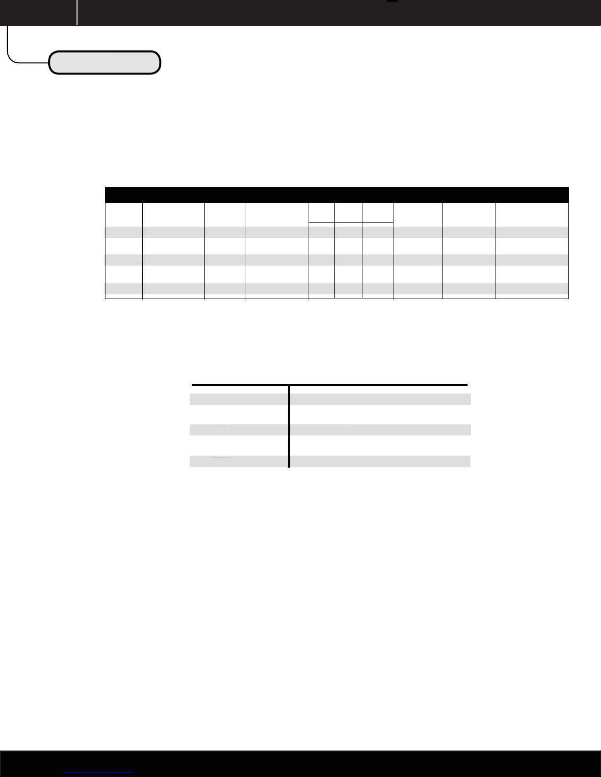
MODEL SPECIFICATIONS
Model CFM @ 80PSI Total HP Tank Capacity Dimensions (inches) Voltage Amps Circuit Breaker
L D H
C1103 3.95 1 20 34 24 29.5 115 13.4 15
C1203 3.95 1 20 34 24 29.5 230 6.7 10
C2106 7.95 2 20 34 24 29.5 115 26.8 30
C2206 7.95 2 20 34 24 29.5 230 13.4 15
C3210 11.85 3 30 46 26 36 230 21.1 30
NOTE: ALL VOLTAGES ARE +/- 5%
MODEL NUMBER MAXIMUM SIMULTANEOUS USERS
C1103 3
1103
C1203 3
C2106 6
C2206 6
C3210 10
NOTE: Number of users based on 1.5cfm @ 80psi per user. Additional equipment such as air abrasion units, blow-guns, and lab equipment should
be factored into the system requirements.
Site Requirement Templates and additional technical information available through our Technical Service Department.
4
1 www.dcionline.com
www.dcionline.com

C1000 Series Service & Maintenance Manual
Theory of Operation
Theory of Operation
THEORY OF OPERATION
While Running
To start the compressor, the user shall activate the compressor head or heads with the power switches located on the front center
of the machine. The selected motors will then begin to run and build pressure in the tank and piping system.
A. The air is taken in through the intake fi lters, located on the rear of each compressor cylinder. The dirt and dust is fi ltered out
of the intake fi lter to 5 microns in this process.
SECTION II
B. The air is then compressed with the pistons in each cylinder, and then travels through the after-cooler (copper) tubing, which
cools the air to help condense any moisture “humidity” taken in during the process of compression.
C. The wet / dirty compressed air and condensed moisture then travel through a coalescing fi lter assembly. This fi lter allows the
condensed moisture to fall to the bottom of the fi lter bowl via gravity, where it will be automatically expelled via the fl oat
drain contained in the bottom of the fi lter bowl. The compressed air also travels through the coalescing fi lter element, which
removes 99.998% of all particles down to 0.01 microns. A fi lter change indicator located on the top of the fi lter housing
shows the condition of the element, and alerts the operator as to when the element is in need of replacement. GREEN
indicates the element has more useful life, while RED indicates the element is in need of replacement.
NOTE: The indicator only functions while compressed air is traveling through the fi lter with compressor running. The indicator
will ALWAYS read “GREEN” with compressors not running.
D. The compressed air then travels through the bottom of the desiccant “drying chamber”, where the remaining contained
moisture is reduced to a pressure dewpoint of -100°F, and then travels into the main storage tank for use in the dental
operatory.
E. When reaching its cut-off pressure of 100psi, the pressure switch will open and the compressor motors will stop.
NOTE: The time operated dryer purge valve DOES NOT open and purge when compressor stops, as it does on most competitive
brands. See Theory of Operation “While Not Running” for more information as to the proper operation of our purge valve.
1.800.624.2793
5
 Loading...