

Page 1
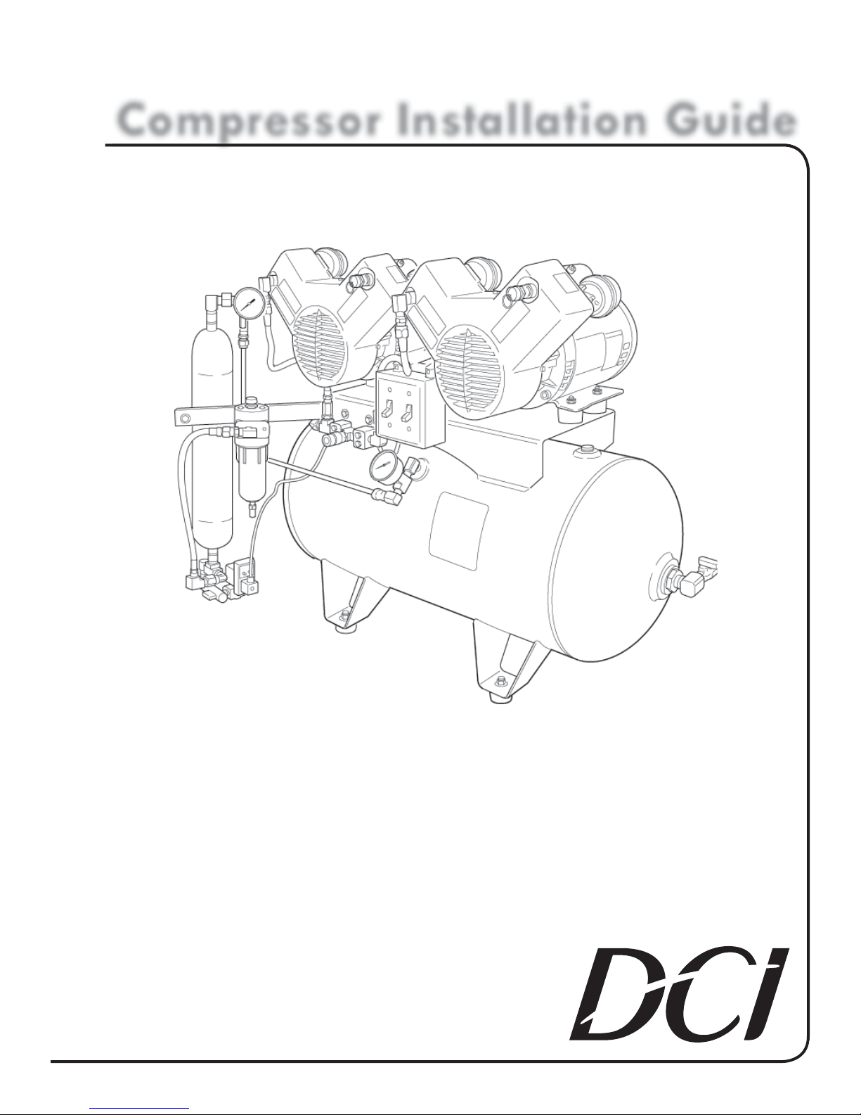
Compressor Installation Guide
C Series
COMPRESSOR
• C1103
• C1203
• C2106
• C2206
• C3210
Copyright © 2006 DCI. All Rights Reserved.
92094, Rev. D, 08/13
Page 2

1 www.dcionline.com
www.dcionline.com
Page 3

C - Series
Compressor
C Series Installation Guide
Compressor Model Specification
Oil-Less
# Heads
Tank
Power
Power
Model # # of Heads Tank Size Voltage Breaker Size Amps
C1103 1 Horizontal 20 gal. 115 20 Amps 13.4
C1203 1 Horizontal 20 gal. 230V 20 Amps 6.7
C2106 2 Horizontal 20 gal. 115V 30 Amps 26.8
C2206 2 Horizontal 20 gal. 230V 20 Amps 13.4
C3210 3 Horizontal 30 gal. 230V 30 Amps 20.1
All Voltage Ratings ± 5%.
NOTE: 1) All machines are of the 3 wire grounded system type.
2) Minimum Breaker size 30 amp & larger wire size #10 supply connection.
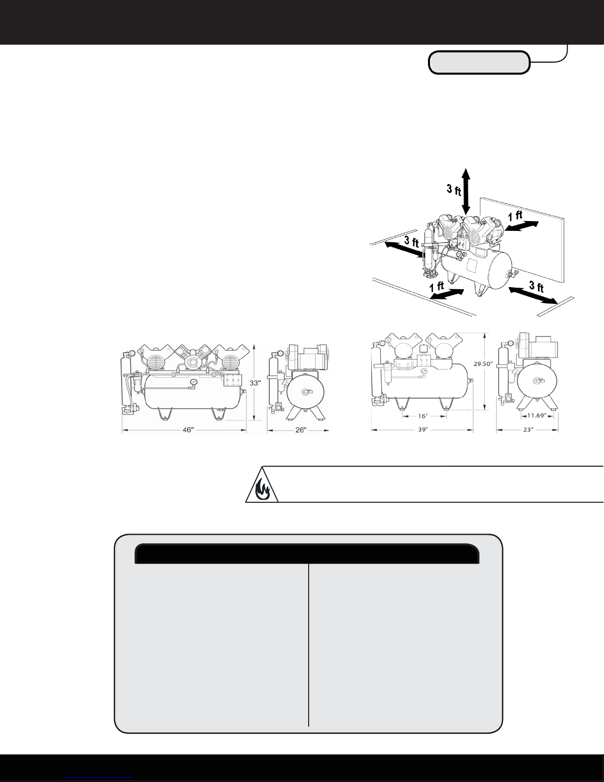
29.50"
33"
16"
39"
11.69"
23"
NOTE: Installation of this product should be undertaken only
If the product does not function as described in the start-up and
test procedures in this manual, call the number below for assistance.
NOTE: Air fl ow rates in excess of compressor ratings will result
Space Requirements
by qualifi ed service technicians.
This product has been factory-tested prior to shipment.
Technical Support: 1-800-624-2793
in reduced performance and possible overheating.
1.800.624.2793
46"
26"
1
Page 4
C Series Installation Guide
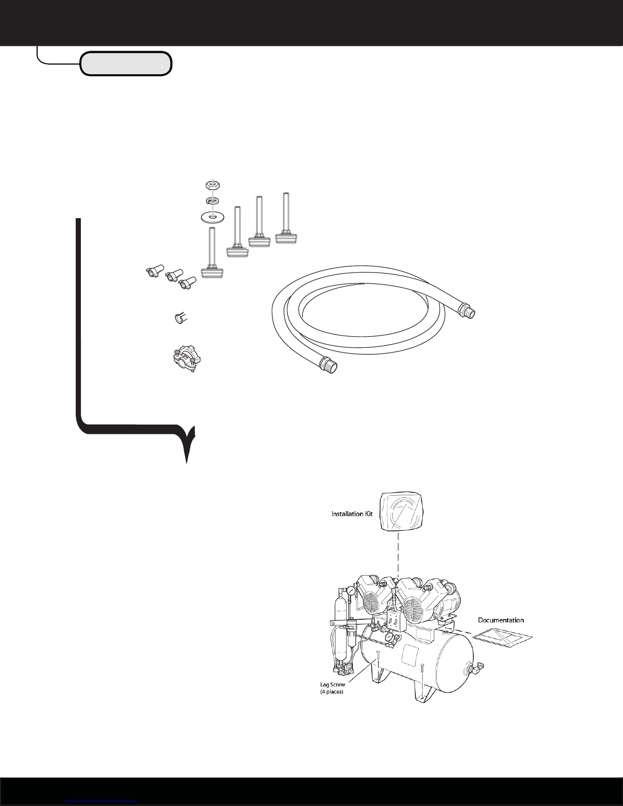
Installation Kit
Compressor Installation Kit
Installation Kit
The C - Series is shipped with the following:
Lock Washer
Flat Washer
Antivibration Foot
Wire Nuts
Nut
Split Bushing
Conduit Connector
You must provide:
Fittings and bushings as required to connect the
•
fl exible hose to the on-site piping (the hose-end
is 3/8 in. NPT “male”).
Earthquake restraints for securing the equipment
•
if required by local codes.
6 ft. Hose
2
www.dcionline.com
Page 5
C Series Installation Guide
Site Requirements
Clearance Site Requirements
Adequate clearance as shown below for servicing and air circulation — room
•
temperature should be maintained between 40°F and 100°F when the motors
are running.
A fl at, level fl oor that provides stable support.
•
Protection from the weather and direct sunlight.
•
A power source within 3 ft. of back-center that provides a dedicated,
•
breaker-protected circuit.
Compressor Site Requirements
WARNING! Fire Hazard! Running motors generate heat. Do not store fl ammable
liquids or objects such as clothing, mops, or brooms near or above the unit.
PLUMBING REQUIREMENTS
1. 1/2 in I.D. minimum pipe size.
2. Pipe connection is to be located within 3 ft of
center back of compressor.
3. Install per all Local and State plumbing codes.
ELECTRICAL REQUIREMENTS
1. 3 wire single phase 115 vac or 230 vac. All
voltage ratings ± 5%.
2. Green Wire is to be grounded to a suitable
system ground.
3. Power supply must be on a dedicated circuit.
4. See data tag for appropriate breaker size.
5. Power supply connection is to be located
within 3 ft of center back of compressor.
6. Install per all local and State electrical codes.
1.800.624.2793
3
Page 6

C Series Installation Guide
Unpacking
n-
Unpacking
Step One:
Unbolt the crate from the pallet
and remove crate intact.
NOTE: Returns must be in the original packaging. Retain the packaging until
installation and test are complete.
Step Two:
Remove the four bolts that
secure the C - Series to the
pallet and put them with the
other packaging.
Step Three:
Mount the four rubber feet.
4
1 www.dcionline.com
www.dcionline.com
Page 7

Step Four:
Grasp the C - Series by the tank and
move it into position.
C Series Installation Guide
Unpacking
Unpacking
NOTE: Returns must be in the original packaging. Retain the packaging until
installation and test are complete.
1.800.624.2793
5
Page 8

C Series Installation Guide
Installation
n-
Installation
Electrical
Step One:
Make sure the power supply is turned off and matches the voltage rating of the motors.
Note: Appropriate Breaker size is listed on the machine data tag.
Step Two:
Connect the power, making sure to adhere to all local and state codes.
Connect the “Green” Ground wire to an earth ground.
Note: 3 wire system.
Step Three:
Attach the fl exible piping and connect to on-site piping.
Install appropriate over current protection; i.e., circuit breaker.
Note:
Model # Breaker Size
C 1103 20 Amps
C 1203 20 Amps
C 2106 30 Amps
C 2206 20 Amps
C 3210 30 Amps
WARNING! Do not connect rigid pipe directly to the compressor. Motor vibration
loosens fi ttings, causing leaks. Use the fl exible pipe provided or a similar substitute.
6
1 www.dcionline.com
www.dcionline.com
Page 9

g
Step One:
Turn off the switches on the front of the compressor.
Step Two:
Ensure that the dryer by-pass shut-off valve is open.
Step Three:
Ensure that strainer shut-off valve is open.
Step Four:
Close outlet valve on the compressor tank.
Step Five:
Apply power to system — the purge valve my emit a hissing sound as the purge timer resets.
Step Six:
C Series Installation Guide
Start-Up & Test
Unpackin
Start-Up & Test
Switch on the motors. If you hear the popping sound of air escaping the relief valve, the dryer by-pass valve is closed.
1.800.624.2793
7
Page 10

g
C Series Installation Guide
Start-Up & Test
Unpackin
Start-Up & Test
Step Seven:
As the tank pressurizes, watch the
pressure gauge. If the pressure switch
is functioning normally, the motors will
shut off at approximately 100 PSI.
Wait fi ve minutes and watch the gauge
to ensure there are no leaks in the
C Series. The system should lose
no more than one PSI per minute.
Step Eight:
Test the purge valve by pressing the
TEST button. If the valve is functioning
normally, you will hear the hiss of air
escaping for approximately ten seconds.
150
BAR
100xkPa
psi
12
180
15
21
18
210
0
0
3
2
4
0
27
0
0
2
1
0
9
9
6
0
6
3
3
0
0
0
8
1 www.dcionline.com
Do not adjust the timer dials on the purge valve.
NOTE!
If the purge timing needs adjustment, call technical support.
www.dcionline.com
Page 11

g
Step Nine:
C Series Installation Guide
Start-Up & Test
Unpackin
Start-Up & Test
150
180
0
2
1
0
9
6
0
6
3
3
0
0
0
210
12
9
BAR
100xkPa
psi
2
15
4
0
18
21
270
0
0
3
Release air using the purge-valve
TEST button and watch the pressure
gauge to see when the motors start.
The motors should start when the
pressure drops to approximately 80 PSI.
You may have to push the TEST button
several times before enough air is
released to lower the pressure to 80 PSI.
Step Ten:
Open the outlet valve on the tank to
pressurize the piping and wait until the
tank is fully pressurized and the motors
stop running.
Step Eleven:
Ensure that no equipment is drawing
pressure from the tank. When no equip-
Loses less than 1 psi per min?
NO LEAKS!
150
18
0
8
100
9
BAR
100xkPa
BAR
100xkPa
psi
0
210
1
2
12
6
0
2
15
40
8
0
18
4
10
1
21
11
270
0
0
6
30
1
psi
0
2
0
1
6
0
9
0
4
4
6
0
2
6
0
3
2
3
0
0
0
0
ment is drawing on the tank, pressure
should drop no more than 1 PSI per
minute.
Watch the pressure gauge. If pressure
drops faster than 1 PSI per minute, an
air leak is indicated somewhere in the
system. Repair as necessary.
1.800.624.2793
9
Page 12

2856
Pressure Gauge
2005
Pressure
Switch
2013
Relief Valve
2012
Intake Element
2135
Check Valve
2014
Drying Chamber
Assembly
2002
1 hp Head
Data Tag
Outlet Ball Valve
2856
Pressure Gauge
2859
Petcock Valve
Bypass Valve
2009
Strainer Shut O
2008 Indicator
2135 Check Valve
2003 Coalescing Filter
2006 Coalescing Element
2007 Float Drain
2011 Automatic Purge Valve (230 Volt)
OR 2848 Automatic Puge Valve (115 Volt)
1 www.dcionline.com
10
www.dcionline.com
Page 13
C Series Installation Guide
g
Unpackin
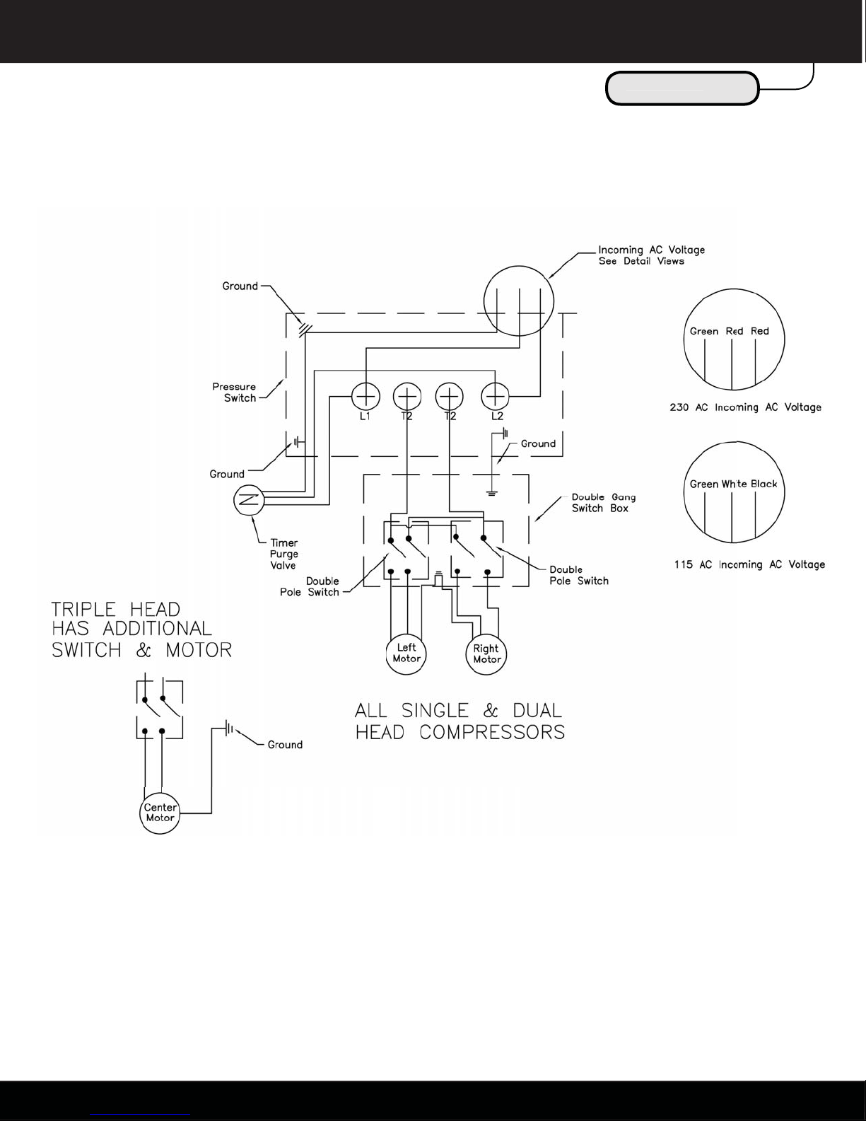
Electrical Schematic
Electrical Schematic
1.800.624.2793
11
Page 14

g
C Series Installation Guide
Plumbing Schematic
Unpackin
Plumbing Schematic
Aftercooling
Tubing
Coalescing
Filter
Condensate
Drain
Left
Motor
Check
Valve
Flow/Check
Drying Chamber
Strainer
Shutoff
Valve
Right
Motor
Check
Valve
Dryer Bypass
Ball Valve
Drying System
Pressure Gauge
To
Storage
Tank
12
1 www.dcionline.com
Time Purge
Valve
www.dcionline.com
Page 15

1.800.624.2793
Page 16

305 N. Springbrook Road
Newberg, Oregon 97132 USA
503.538.8343
800.624.2793
www.dcionline.com
 Loading...