

Page 1
DCE
Data Sheet 367E
(GB)
tJn
aster'
DUT NTR
UNT
RE UM
025
A
for cleaner
motor
cover
removal
--
-
Ouick-release
sealer
gear
--d
B
t
230
min
clearance
cleaned
air outlet
required for
marntenance
Terminal box
Joint line
c
I,
t
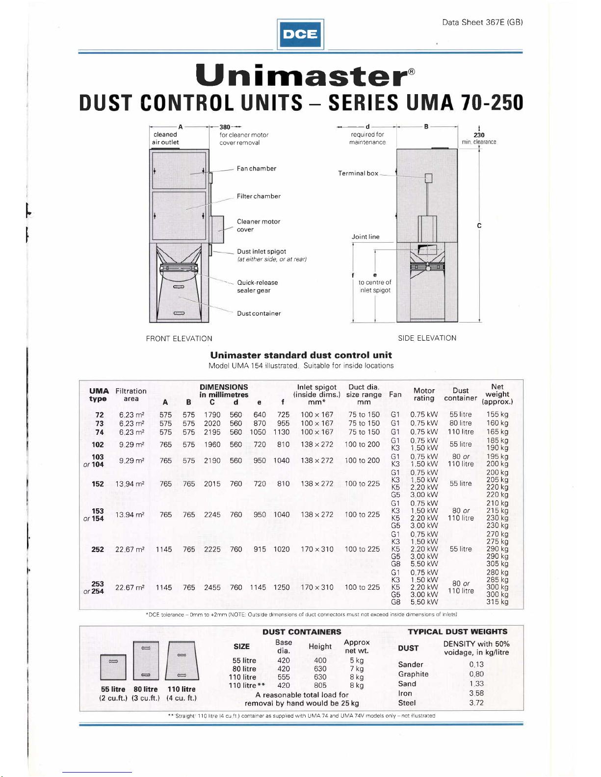
Fan chamber
Filter chamber
Cleaner motor
cover
Dust inlet spigot
(at
either side, or at rear)
e
to centre of
lnlet sprgot
Dust container
FRONT ELEVATION
SIDE ELEVATION
Unimaster
standard dust control unit
lVlodel UtVA 154 illustrated Suitable
f
or
inside locations
UMA Filtration
type
area
A
575
575
575
765
B
DIMENSIONS
in millimetres
cd
e
lnlet
spigot
(inside
dims.
f mm*
725 100
x
167
955
100
x
167
1 130 100
x
167
810 138x212
Duct dia.
)
size range Fan
mm
Motor
rating
Dust
conta iner
Net
weight
(approx.)
155 kg
160 kg
165 kg
185
kg
190
kg
19s kg
200 kg
200 kg
205 kg
220
kg
220 ks
210 kg
215
kg
230 kg
230 kg
210 kg
215 k9
290 kg
290
kg
305 kg
280 kg
285
kg
300 kg
300
ks
s15kg
72
73
74
102
103
or 1O4
623m2
623m2
623m2
929m2
575 1 790
s7s 2020
575 2195
575
1 960
560 640
560 810
560
1050
560 720
75
to
'1
50
75to150
75to150
1 00 to 200
G1
G1
G1
G1
K3
G1
K3
G1
K3
K5
AE
G1
K3
K5
G5
G1
K3
K5
G5
G8
(Jt
K3
K5
G5
GB
0.75
kw
075kw
075kw
55
litre
80 litre
1
1
0
litre
55 litre
80 or
1 1 0 litre
9
29 m2 165 515 2190 560 950
1 040 138
x
272 1 00 to 200
0
1
0
1
0
1
2
a
0
1
2
3
0
1
2
3
5
0
1
2
75 kW
50
kw
75 kw
50 kw
75 kw
50 kw
20 kw
00 kw
75 kW
50
kw
20 kw
00
kw
75 kW
50
kw
20
kw
152 13 94 m2 765
765 2015 760 720 810
138x272 100
to
225 55
litre
or
153
154
252
1 3.94 m2 765 765
2245 760
950
1 040 138
x
272 100 to
225
80
or
1
1
0
litre
22 67 m2 1145
765 2225 760 91 5 1020 1 70
x
31 0
100
to
225 55
litre
253
or254
22.67 m2 11 45 165 2455 760
1
145
1250
.1
70
x
31 0
1 00 to 225
00
50
75
50
20
KW
KW
KW
KW
80 or
1'l 0
litre
3.00
550
'DCE
toleraoce
omm to
+2mm
(NOTE:
Outs de drmens ons
of duct
conneclors
must not exceed insrde drmens ons
of rn
ets)
**Straght
110ltre(4cuft)contanerassupphedwrthU[,4A74andUNr]AT4Vmodelsony
notrlustrated
55
litre
80
litre 110 litre
(2
cu.ft.)
(3
cu.ft.)
(4
cu. ft.)
A reasonable
total
load for
removal by hand
would
be
25 kg
slzE
55
litre
80
litre
110 litre
110
litre
*r
DUST CONTAINERS
TYPICAL DUST WEIGHTS
DUST
DENSITY with 50%
voidage,
in kg/litre
013
080
133
358
312
Base
dia.
420
420
555
420
Height
400
630
630
805
Approx
net wt.
5kg
7kg
8kg
8ks
Sander
Graphite
Sand
lron
Steel
Page 2
DCE
Fan chamber
Terminal box
Filter chamber
Cleaner
motor
cover
Seating level
FRONT
ELEVATION
SIDE ELEVATION
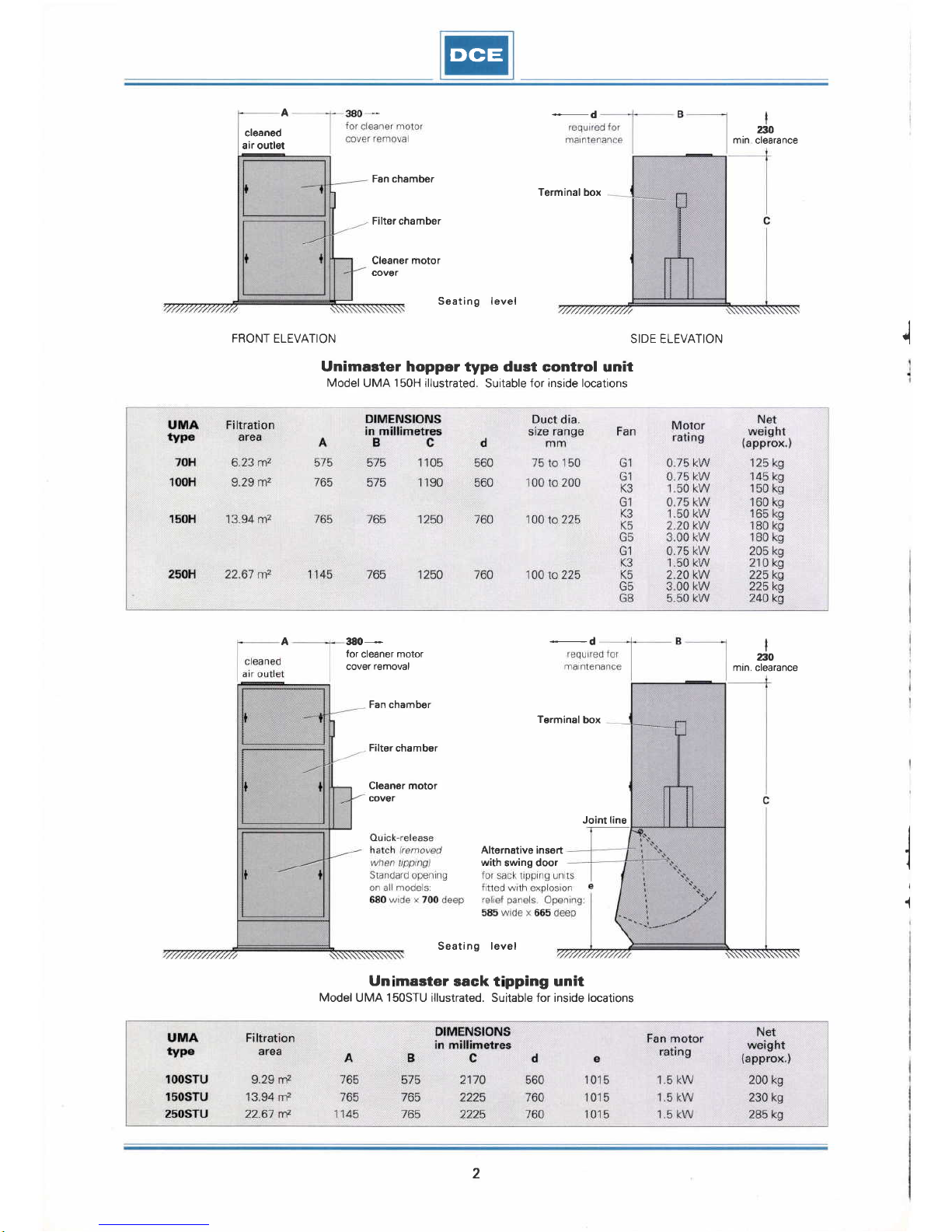
Unimaster hopper type dust
control unit
Model UMA
150H
rllustrated.
Suitable
Jor inside locations
cleaned
air outlet
380-----
for
cleaner
motor
cover
removal
min clearance
t
ato
I
ao
min. clearance
A
A
I
-d
Fan chamber
Filter
chamber
Cl6aner motor
cover
Terminal
box
Alternative insert
with
swing door
Joint line
Seating level
Un master
sack t
pping
unit
Model
UMA
150STU
illustrated. Suitable for inside locations
I
2
Page 3
DGE
A
cleaned
air outlet
cleaned
air outlet
380
_
for
c eaner
motor
cover
removal
Filter
chamber
Cleaner
motor
cover
380
*
for
c eaner
molor
cover
removal
-
d
requrred for
ma
ntenance
.equ
red for
marntenance
B
I
230
mrn c earance
I
230
mrn
cleara
nce
c
Seating
level
FRONT ELEVATION
SIDE
ELEVATION
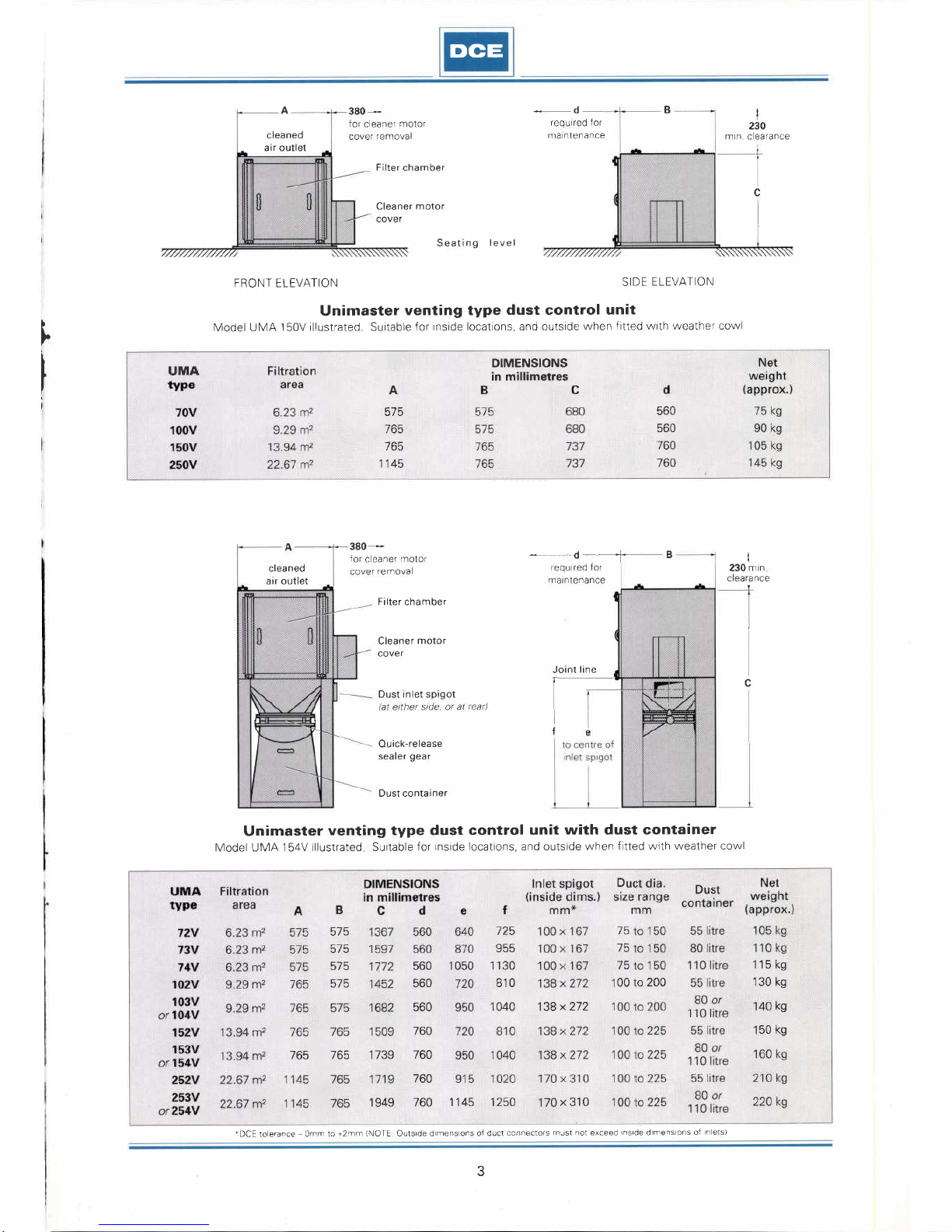
Unimaster
venting type
dust control unit
lVodel UMA
150V illustrated Surtable
for rnside locatons, and outside
when fitted
wrth weather cowl
-dB
Filter chamber
Cleaner motor
cover
Joint
line
Dust inlet spigot
(at
etther stde, or at
rear)
Ou
ick-release
sealer
gear
Dust container
Unimaster
venting type dust
control unit
with dust container
lVodel UMA
154V rllustrated Surtable
for rnsrde locatrons, and outsrde
when
fltted wrth weather cowl
c
f
I
T
UMA
DIMENSIONS
in millimetres
A
575
765
765
1145
560
560
760
760
D
760
kg
560
560
560
760
50 kg
138
x
272
B
575
575
575
515
1 050
00 to
200
x
310
l5
75
1E
765 765
1139 760
1949 760
125
955
1 130
810
1 040
1145 1250
115 kg
130 kg
DCE to erance omm 10
+2mm
INOTE
Outsrde
d
mens
ons of duct
connectors
must
not
exceed
rnslde d mens ons ot n eIS)
3
Page 4
DCE
85
tlo
35
35
575 6t15 575 645
180
40
35
35
UMA 70H
and 70V
UMA 100H and 100V
85
35
85
11
35
35
35
12
UMA 150H and 150V
UMA 250H and 250V
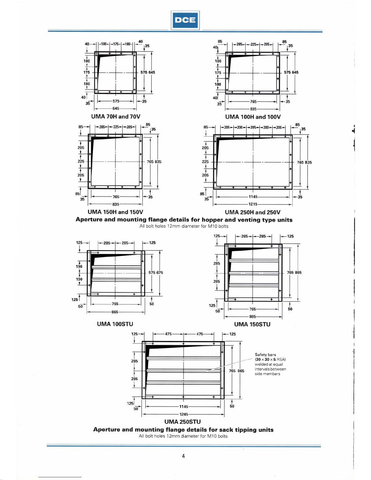
Aperture
and mounting
flange details
for hopper and venting
type units
All
bolt holes
12mm
diameter for M10
bolts
285 125
125
175
85
i
35
35
125
125
50
50
UMA 1OOSTU
UMA lsOSTU
125
Safety
bars
(30x30x5RSA)
welded
at equal
intervals
between
side members
11
50
UMA 25OSTU
Aperture
and mounting
flange details for
sack tipping
units
All bolt holes
I 2mm diameter f or M 1 0 bolts
I
4
Page 5
DCE
A
J
Secondary
filters
and
absolute
filters
b
c
F
K
T-
s
r
m
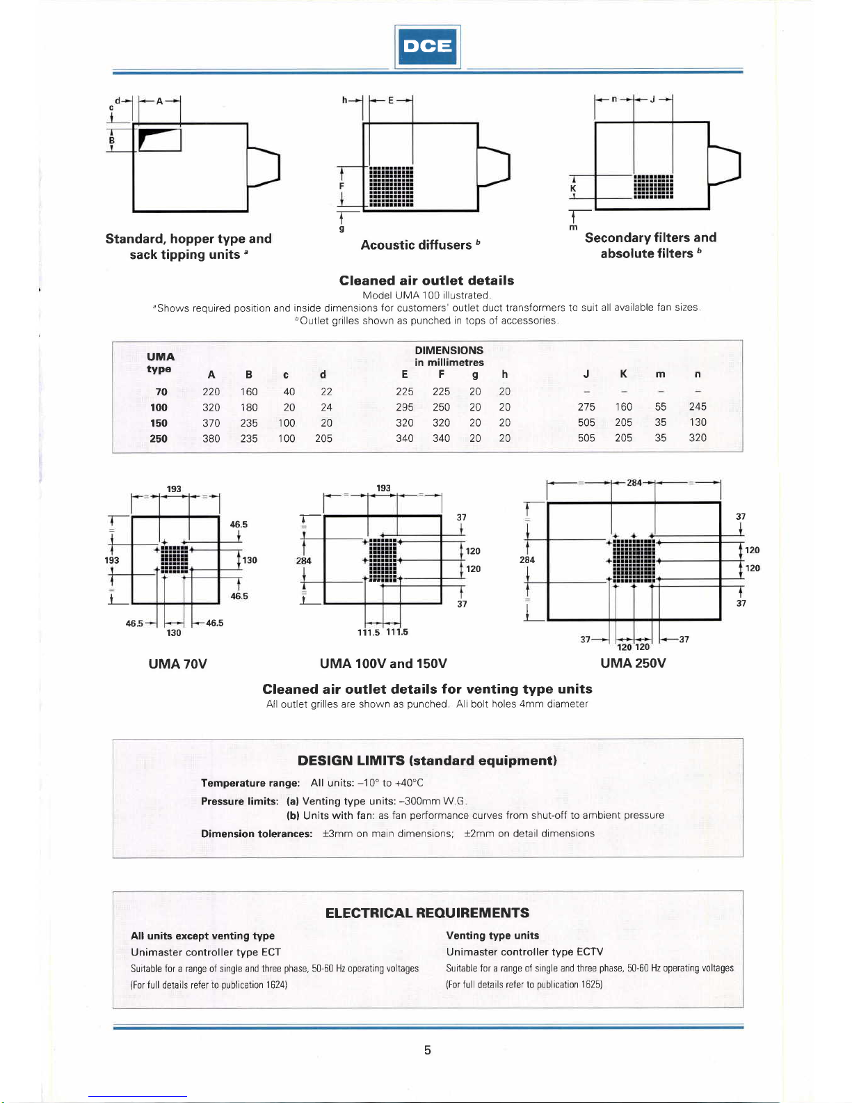
Standard,
hopper type and
sack tipping
units'
193
Acoustic diffusers
b
Cleaned air outlet
details
Model UMA
100 illustrated
,Shows
required
position
and inside dimensions
for
customers'outlet
duct transformers to suit
all available fan sizes
bOutlet
grilles
shown as
punched
in tops of accessofles
45.5
T-
37
120
120
193
193
r
t_
37
130
t
37
46.5
130
111.5
11 .5
120
UMA 7OV
UMA 100V and 150V UMA
25OV
Gleaned air outlet details
for venting
type
units
All
outlet
grilles
are shown as
punched
All bolt
holes 4mm
diameter
DESIGN
LIMITS
(standard
equipmentl
Temperature range:
All
units:
-1
0'
to
+40'C
Pressure limits:
(al
Venting type units:
-300mm
W G
(bl
Units
with fan: as fan
performance
curves
from
shut-off to ambient
pressure
Dimension tolerances:
+3mm
on main dimensions;
+2mm
on
detail dimensions
ELECTRICAL
REOU IREM ENTS
All units exc6pt
venting type
Unimaster controller type
ECT
Suitable for a range of
single and three
phase,
50-60 Hz operating voltages
(For
full details refer
io
publication
1
624)
Venting
type
units
Unimaster controller type
ECTV
Suitable
for a range of single and three
phase,
50-60 Hz operating
voltages
(For
full
details
refer to
publication
1 625)
284
120
120
37
t
465
37
UMA
type
DIMENSIONS
in millimetres
A
220
320
370
380
B
160
180
235
235
c
40
20
100
100
d E
225
295
320
340
Fgh
225 20
20
250 20
20
320
20 20
340 20
20
JKm
n
70
100
150
250
22
24
20
205
275
505
505
160
205
205
trtr
atr
35
245
130
320
5
Page 6
DCE
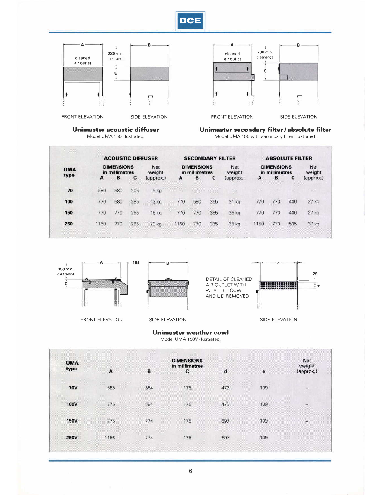
A
A
DETAIL OF CLEANED
AIB
OUTLET
WITH
WEATHER
COWL
AND
LID
REIVIOVED
cleaned
air outlet
FBONT ELEVATION
SIDE ELEVATION
Unimaster acoustic diffuser
Model
Ult/lA
150 illustrated
I
150 mrn
clearance
A
194
cleaned
air outlet
c
FRONT
ELEVATION SIDE ELEVATION
Unimaster secondary
tilf.er
labsolute
filter
Model
UMA
150 with secondary filter
illustrated
230
mtn
clea rance
,rolrn,n
clearance
c
T--]
rr
l
d
L"
c
e
I
FRONT
ELEVATION
SIDE
ELEVATION
Unimaster
weather cowl
Model UMA 150V rllustrated
SIDE ELEVATION
6
Page 7

DGE
I
'MEtvIBREX'
HELIEF I.4EI\,48BANE
ilPLOSION
20
UMA
70 explosaon relief flange
Prtch
centresr
140mm vertrcally; 130mm horzontally
708
40
581
501
40
74
20
UMA 150 explosion relief
flange
Prtch centres. 150mm vertrcally; l30mm
horizontally
NOTE
1t04
UMA 250 explosion relief
flange
Pitch
centres
130mm vertrcally, 135mm horrzontally
40
40
668
20
40
40
20
40
534
40
44
4
520
574
51
5
492
20
75.5*
to
lornt
lrne
455
27
20
14
74
20 20
UMA
100
explosion
relief flange
P
tch centres:
140mm vertically, 130mm horizontally
66.5'to
lornt
lrne
20
75.5* to
lornl
ne
20
44
20
20
541
458
74
74
20
99.5+ to
loint
ine
Explosion
relief flange mounting
details
Alvertrcai
holesdrilledl0mmdiameterforlVSbolts Alhorzonta hoesthreadedtoacceptttulSbolts
*lncrease
dimensron by 38
for ventrng
type unrt
wrthout
bottom assembly
N4ountrng f lange
prolects
1O0mm beyond
rear
of
f lter
K3 sound
leves
taken
at
typcal
arvoume of 1000 mr/h K5 sound
leves
taken al a
typcal
a
r
voume of
1500 m3/h
*Secondary
friter and absolute
frter.ot
suppl ed wth Gl
tan
I
I
,MEIUBREX'UPLOSION
SELIEF
IVEMBRANE
+ +
All
readings were
taken
in
sem
andl 5metresabove
WEIGHTED SOUND
PBESSURE LEVELS
Unit only
With
acoustic diffuser
With secondary filter
With absolute filter
7
Page 8

DCE
400
350
300
250
200
150
100
50
a
=
E
E
F
L!
I
z
F
ul
CC
l
U)
ct)
L!
t
o-
(_)
F
F
(./)
15{t0
2000 2500 3000
AIR VOLUME
(m3lh)
These curves were obtained f rom volume and
pressure
readings taken at unit rnlet with the
filter
clean.
Standard and Hopper type units
To
select the
most
suitable unit
for
a
given
application:
1 Determine the
air
volume, in m3/h, needed
to entrain the dust.
2 Estimate
pressure
drop through
connected system
-
i.e. between
point
of
entrainment and unit inlet.
3
Assess
pressure
drop across
filter
prior
to
shaking, usually 50-1 00mm
W
G
4 The
sum of 2 and 3 = W.G.
required
5 Consult
graph
for fan
performances
available.
Sack Tipping Units have K3
(1
5 kW)
fans
with modified
outlet to ensure adequate
face
velocities at the tipping hatch under normal
operating conditions
Typically, the exhaust
rate for the
UIVA
250STU is 1275m3/h
(750
cfm)
0593
0
500
1000
3500 4000
Unit
performance
curves
DCE
LIMITED
Thurmaston
LEICESTER LE4 8HP England TEL LEICESTER
(0533)696161
FAX
(0533)
693028
rELEx342409 DUST G
THE DCE
GROUP OF COMPANIES
@)
DCE Ltd, Leicester
@)
DCE DEUTSCHLAND GmbH, Dusseldorf
@)
DCE BENELUX BV, Wormerveer
G)
DCE SA, Paris
G)
DCE IBERICA SA, Barcelona
@)
DCE SCANDINAVIA
^y'S,
Copenhagen
@)
DCE,
lnc
,
Jelfersonrown,
Ky
GD
DCEVOKES(Pty)Ltd,Springs,Tvl
(ND
ACCO,Calcuua(DCElicensee)
@
HUYCKDCEKK,Yokohama
@)
DCE VOKES fty Ltd, Sydney, Vtelbourne & Brisbane
6>
DCE FILTERS Ltd, Auckland
Fepresented in
principal
countries throughout
the world
DATA SHEET 367E
(GB)
dust control equipment for industry
Unimastero
quality
dust control units Dalamatico automatic reverse
jet
filters Sintamatic'' advanced technology dust filtration
DCE reserve
the
right
to alter design without notice Freedom from
patenl
restrictions must
not
be assumed
Page 9

lrla
@
T LL
TY
T9, 12, 23 30
FUNCTION
This controller
ensures the efficient
cleaning
of
the
filter
mattress
on initiation of a cleaning
rycle
after
each
dutycycle of
the
Unimaster dust control
unit.
To
protect
the Unimaster filter fabric, the
controller
is interlocked so.that the fan motor
cannot
be
restarted during the operation of the cleaner
motor.
SPECIFICATION
The equipment is housed
in
a
rigid
H/C box
designed
to
lP65
protection,
with
cable entries
at top
and
bottom.
Functioning
as a dual direct-on-line
starter,
it
comprises
(1)
a double-wound transformer
with
a
selection of input tappings for the
incoming supply,
gMng
an
output of 24Y AC;
(2)two
contactors
labelled
K1 and K2
(electrically
interlocked to
prevent
simultaneous operation) to control the
fan and cleaner
motors;
(3)
a thermal overload
relay with
single
phase protection
for the fan motor
(no
protection
being
supplied for
the cleaner
motor except
where
required
by national
regulations,
as
in France);
(4)
a
pre-set
electronic
timer
module controlling
the
'fan
rundown' and'cleaning'
periods.
These components
are all
mounted
on a baseplate
within the box.
Timer
ambient temperature
range is
-5"C
to
+40'C.
For temperatures
outside these
limits
please
refer
to DCE.
!NSTALI.ATION
Mount
the controller
independently of the Unimaster
dust control unit on a vertical surface
free of
vibration.
Bring
the
incoming
mains
via
a
switch-fuse
unit
(preferably
'on-load'
typelto the terminal
block,
{see
Table
1
for the fuse rating). Seal all
joints
at conduit
entry
holes
to
prevent
dust entering
the box.
Publication
16244
(GB)
OVERLOAD
SETIING
IMPORTANT
Before start-up,
the overload
relay
calibration
lever must be set
at the value
given
by
motor
full load current
in Table
2.
OPERANNG
RANGE
The controlldr
is.suitable
for use on a
range of
3-phase,
50
-
60
Hz operating
voltages,
with fan
motors
rated up to and
including some
at 11 kW.
A
stardelta
(Y/A)
controller,
type
ECT SD, is available
for other
11 kW fans. S6e
Table
2.
A variance
of t10o/o is
allowable on transformer
input tappings.
OPERATION
1. START
(average
operating
period
for fan, 4 hours)
Press
'START'
button:
o Fan
contactor K1
is
energized;
timer
module
sets
and
fan motor runs.
2. CLEAN
Press'CLEAN' button:
o Fan
contactor
K1 is de+nergized
and the
timer
energized.
O After
approximately 90
seconds
cleaner
motor
contactor
K2 is energized;
cleaner motor
now
runs
for approximately
45 seconds.
o Cleaner
motor
contactor
is
decnergized
and
the
timer
resumes inactive state.
Before
a cleaning
cycle can be
initiated
by
pressing
the
'CLEAN'
button,
thefan
contactor
K1 must
have
remained
energized
for at least
30 seconds.
A
'fail-safe'feature ensures that
if the
power
supply
fails
while the timer
is
performing
a cycle,
then
re-
applying
the
power
will not cause
the cycle
to be
completed.
I nstead, the controller
will
automatically
re-set
ready for the fan to
be restarted.
KW
0.18
0.50
0.55
0.75
1.10
1,50
2.20
3.00
4.00
5.50
7.50
11.00
1.28
1.65
2.30
3.22
4.32
5.70
7.40
9.80
13.80
19.30
'1.26
1.60
2.20
3.15
4.20
5.40
7.00
9.20
13.00
18.20
Single Phase
110v
220v
240v
4.4
7.4
9.7
14.0
20.0
Table2-MotorCurtents
Three
Phase
200v
220v 380v
415v 440v
1.40 1.20 0.75 0.69
0.65
2.2 2.2
3.3
3.3
4.t 4.7
6.5 6.5
,r_
r:
2.50
2.40 1.40
3.30 3.10
1.80
4.60 4.30
2.50
6.47 6.05
3.50
8.70 8.13
4.70
11.7810.72 6.20
15.4014.00
8.10
20.3018.5010.70
28.50 25.90
15.00
39.90 36.30
21.00
Figwes
in-amps lor
motds
o,
otlrcrSrlcY-
Spaces
marted
le, not suitablo
to.
application
FLC
Amps
0.00
-
0.45
-
0.95
-
1.51
-
4.00
-
Tablel-FuseRadng
HRC'Amp
Rating
Fuse Wire
Amp Rating
6
8
'12
16
30
o.M
0.94
1.50
3.90
6.25
2
4
6
10
16
20
25
32
40
50
63
6.26
7.76
10.01
12.21
17.2'.1
21.61
7.75
10.00
12.20
17.20
21.60
29.00
T
Fuse
\Nire
not
recommended
'HRC.
High rupturing capacity.
HRC Fusas: BS
88
Pan 2 1975
Class
0l l.E.C. 21 69:2
Fuse
wiro
sire basod
upon
sir
times
full load
curent
Page 10

DCE
TERMINAL
STRIP
T
Lg
S
Lz
R
Lr
l
KT
xl
A2
,a
69
TERM
INAL
BOX
l-
,
I
\
SFIAKER
ttt
,/
-
11-
('
\/
FAN
r-l
It,
I
Standard
Wiring
Diagram
for Types
ECT 9
& ECT 12
(3-wire
supply)
lf
controller
differs from
this, refer
to diagram in
lid
TERMINAL
STRIP
T
La
S
Lz
R
Lr
I
-(
j
I
M
5-
HAKER
S
FAN
l-l_l
ly',
\/
I
)'
l
\
I
UNIMASTER
CONTROLLER,
Type Ecr
9 & Ecr 12
(3-wire
suppty, with
two
overtoads)
DCE
LIMITED
Thurmaston
LEICESTER
LE4
8HP
England
TEL
LEICESTER
(05331
6961
61 FAx
(0533)
69302g
TELEX
342409 DUST G
llJ
J
f
o
o
=
IE
IIJ
=
F
AT
t
t3
K2
START
,Q
R
CI.EAN
t
13
21
START
2
,a.
LlJ
J
f
o
o
=
E
UJ
=
tr
Publication
16244
(GB)
0691
Page 11

Publication 85B
Cleaned air
outlet
Fan
chamber
access
panel
Fan
motor
Four captive
wing-nuts
secunng
filter
assembly
Slide
in
guides
Filter assembly
Filter chamber
access
panel
Cleaner motor
Shaker bar
Filter bag
showing wire
mesh insert
lnlet
duct
connector
bt either side
I /or at rear)
Ouick-release
sealing
gear
Dust
container
Locating
stops
When ordering spares or
accessories
PLEASE
OUOTE SERIAL
NUMBER OF UNIT
IN FULL
(See
plate
adjacent
to shaker motor cover)
DCE
This
dust control unit has been
carefully
designed to
give
efficient trouble-free service
provided
the following instructions
are adhered
to:
a
Explosion relief
panels,
if fitted,
should
be vented
to a safe area, Any
relief duct must be straight, as
short as
possible
(3
metres
max.
)
and strong
enough
to withstand the
pressure
of an
explosion.
a
Do
not
start
the fan if access
panel(s),
filter
assembly or dust container are
not in
place
and
fastened.
a
Clean the
filter at least twice in a working day
(see
OPERATION
below).
a
Do not overfill the
dust container or allow it to
become too heavy for removal and emptying.
NOTE _ ALWAYS ISOLATE
THE ELECTRICAL
CONTROLS BEFORE SERVICING
OPERATION
The START button on
the
Unimaster
FE controller
operates the
fan motor. Dust-laden air
is
drawn into
the
unit beneath the
filter assembly as shown in the
illustration,
heavy
particles
falling directly
into
the dust container.
As
the air
passes
through the
filter the finer dust is deposited
on
the
outer surfaces
of the filter fabric.
The fan handles
cleaned air only, discharging
it through the outlet at the
top of the unit.
The
CLEAN
button switches off the
fan motor and
automatically starts the two-part
cleaning cycle. First,
there is
a
'dwell' period
of approximately 90 seconds to
allow the fan
to
run down;
secondly, the cleaner motor is
activated for about 45 seconds, imparting
a
vigorous
shaking action to
the filter to dislodge accumulated dust.
lf air were drawn through
the filter while it was being
shaken,
the dust, instead of being dislodged, would
become deeply embedded in the
fabric
and cause serious
@
OPERAT ON
ET
MA NTENANCE NSTRUCT
ONS
loss of suction. The two motors are therefore
interlocked
by the controller so that the
fan
cannot
be restarted until
the
cycle has been completed. Following a
power
failure
the timer automatically
resets itself so that the Unimaster
can only be operated again by
pressing
the START
button.
Full
details
of
the
controller
are
given
in Publication
110.
DUST DISPOSAL
(for
models with container and
quick-
release sealing
gear,
as illustrated).
a Release container f ully by
raising
sealing
gear
handle.
b
Remove
and empty
the container.
c
To replace, slide container back to the
locating stops.
d Lower the sealing
gear
handle.
TO REMOVE FILTER ASSEMBLY
a lsolate electrical controls and
remove both access
panels.
b
Fully
slacken
the four
captive
wing-nuts located in the
fan chamber.
c Withdraw complete
filter
assembly
through front of
filter chamber.
d Remove wire mesh
inserts from individual filter bags.
e Detach filter bag assembly from supporting
frame.
TO REPLACE
FILTER
ASSEMBLY
a
Fit filter bag assembly into supporting frame, feeding
individual
filter
bags between
locating bars, and fold
collar over
peripheral
sealing flange.
b Replace wire mesh inserts in filter bags.
c Slide
filter
assembly
into the
guides
until bottom
corners of filter bags make contact with the shaker bar.
d
Locate individual filter bags in shaker bar.
e Slide
filter
assembly
fully home and tighten wing-nuts
to form air-tight seal.
f Replace and fasten access
panels.
INADEOUATE
SUCTION CAN
BE
CAUSED
BY:
1
Motor
running
the wrong
way. Check with anow show-
ing direction of rotation, situated on the motor base.
2 Access
panels,
filter
assembly or
dust container not
properly
sealed.
3 Choked
filter.
4 Dust container overfilled.
5 A restriction in the suction ducting or cleaned air outlet.
REGULAR SERVICING Every 1,000
working hours
(approximately
6 months at
zl0
hours
per
week) the filter fabric,
shaker mechanism and all dust seals should be
checked and any defective
parts
replaced. Please ask for details
of the
DCE Maintenance Service Scheme, which is in
operation throughout mainland England,
Scotland
and Wales.
DCE L M TED
Thurmaston
LEICESTER LE48HP England
O,
Leicester
(0533)696161
Fax
(0533)
693028 Telex 342409 DUSTG
Page 12

EDE
Issue
9
Page
1
of 8
Unimaster
UMA 70-250
*gA
*98
*9C
*9D
*gE
*9F
*gG
*9H
*1
0A
*1
0A
*1
0B
*1
0B
*1
0c
*1
0c
*1
0D
*'l0D
*7F
*7G
*7H
1A
1B
1C
1D
1E
*74
*78
*7C
*7D
*7E
27572-579
27572-590
27572-596
27572-607
27572-617
44824-921
44824-922
44824-923
M824-924
44824-928
44824-929
44824-930
44824-931
44824-005
44824-006
44824-007
44824-008
44824-305
4r'.824-306
44824-307
44824-308
42772-502
42772-502
42773-502
42773-502
42772-503
42772-503
42773-501
42773-501
1HP
MOTOR
TEFC
O.75KW
sOHZ & 6OHZ
MOTOR
ONLY
2.2KW
gOL
FRAME
sOHZ & 6OHZ
4HP MOTOR
3KW lOOL
FRAME
sOHZ
& 6OHZ
5.5HP MOTOR
4KW
112M FRAME
sOHZ &
6OHZ
7.5 HP MOTOR
5.5 KW 132
FRAME
TOP FRAME,BAG,INSERT
AND
EDGINGS
COMPLETE
COTTON
UMATO
TOP FRAME,BAG,INSERTAND
EDGINGS
COMPLETE
COTTON
UMA1OO
TOP FRAME,BAG,INSERT
AND
EDGINGS
COMPLETE
COTTON
UMAl50
TOP
FRAME,BAG.INSEBTAND
EDGINGS
COMPLETE
COTTON
UMA25O
TOP FRAME,BAG,INSERT
AND
EDGINGS
COMPLETE
POLYPROPYLENE
UMATO
TOP
FRAME,BAG,INSERT
AND
EDGINGS
COMPLETE
POLYPROPYLENE
UMAlOO
TOP FRAME,BAG,INSERT
AND
EDGINGS
COMPLETE
POLYPROPYLENE
UMAl50
TOP
FRAME,BAG,INSERT
AND
EDGINGS
COMPLETE
POLYPROPYLENE
UMA25O
MULTIPLE
FILTER
BAG
COTTON
UMATO
MULTIPLE
FILTER
BAG
COTTON
UMA1OO
MULTIPLE
FILTER
BAG
COTTON
UMA]50
MULTIPLE
FILTER
BAG
COTTON
UMA25O
MULTIPLE
FILTER
BAG POLYPROPYLENE
UMATO
MULTIPLE
FILTER
BAG POLYPROPYLENE
UMA1OO
MULTIPLE
FILTER
BAG POLYPROPYLENE
UMA150
MULTIPLE
FILTER
BAG POLYPROPYLENE
UMA25O
COTTON
INSERT
EDGINGS
FOR
UMATO
COTTON
INSERT
EDGINGS
FOR
UMA1OO
COTTON
INSERT
EDGINGS
FOR
UMA150
COTTON
INSERT
EDGINGS
FOR
UMA2sO
POLYPROPYLENE
INSERT
EDGINGS
FOR
UMATO
POLYPROPYLENE
INSERT
EDGINGS
FOR
UMA1OO
POLYPROPYLENE
INSERT
EDGINGS
FOR
UMA150
POLYPROPYLENE
INSERT
EDGINGS
FOR
UMA2sO
1
1
1
1
18
18
12
1
1
29
I
1
I
29
1
1
1
1
1
'l
1
1
2
Item no.
Description
Part
number
The above items
are always
stocked and readily
available.
For items
not
listed contact
DCE
Spares
departmerit
for
availability
DCE
L
M TED
Thurmaston
LEICESTER
LE4
8HP England
TEL
LEICESTER
(0533)
696161
FAx
(0533)
693028
TELEX
342409
DUST
Page 13

ED
The above items
are always stocked
and readily
available. For items not listed
contact DCE
Spares department
for
availability.
DCE
L M
TED
Thurmaston
LEICESTER LE48HP
England rEL
LEICESTER
(0533)696161
FAx
(0533)693028
rELEx342409
DUST
lssue 9
Unimaster
UMA
70-250
11A
11B
12
13
144
148
14C
14D
15
178
17C
24
24
16
174
41
353-026
41353-027
27572-541
41157-103
44571-002
44571-009
44572-002
44571-016
18165-223
3531
1-519
18165470
18165-481
18165-481
41121-112
41121-139
*Multiple
filter
bags
and lnsert edgings other than
Cotton
or Polypropylene
are available to order,
e.g. Nylon
and
Terylene.
BAG TNSERT
UMA70
(12)&
UMA1oo
(18)
BAG INSERTS
UMA150
(18)&
UMA2sO
(29)
SHAKER MOTOR
O.18KW
3PH SOHZ
BIN
SEALING
GEAR
TV/O
CU.FT. BIN
THREE
CU.FT. BIN
FOUR
CU.FT. BIN
FOUR
CU.FT. BIN
UMATO ONLY
RUBBER
SEAL
25MM
X 12.5MM X l4OOMIV
Length 1400mm
BIN
CANVAS
SLEEVE
DOOR
SEALING RUBBER
22MM X
8MM
UNIT FAN
CHAMBER
STU BASE
U|VA7O
1850mm
UMA100
2450mm
29O0mm
UMA150
2450mm
2900mm
UMA250
3200mm
2900mm
DOOR
SEALING
RUBBER
VENTING
UNIT DOORS
UN/A70V
2150mm
UMA100V
2600mm
UMA150V
2750mm
UMA250V
3500mm
DOOH
SEALING RUBBER
FILTER
MATTRESS
DOORS
UMATO
2,I5OMM
UMA1OO
26OOMM
UMA150
275OMM
UMA2sO
3sOOMM
COMPLETE
SET
OF
DOOR FASTENER
PARTS
lncluding:
Handle,
washe(l/32)
",
washer(3/32)",
cam,
binx nut
M6, and
washer
M6
FASTENER
PARTS FOR
EXPLN
DOORS
(OUTER)
1
1
1
1
1
1
1
1
1
1
Item
no.
Description
Part
number
Page 14

DE
The
above items are always
stocked
and
readily
available.
For
items not listed
contact DCE Spares
department
for availability
DCE
L M TED
Thurmaston LEICESTER
LE4
8HP England TEL
LEICESTER
(0533)
696161 FAx
(0533)
693028
TELEX
342409 DUST
Unimaster
UMA 70-250
31
36E
60A
608
60c
60D
53
54
55
35C
35D
36C
36D
36F
36G
39B
464
468
46C
65A
658
65C
65D
41121-140
41 1
55-023
41155-024
43141-113
43141-114
43141-112
43141-111
43143-517
43143-518
43171-013
43171-014
43171-015
42332-508
640-B-43
42335-51
0
640-3339
640-334'l
640-3344
640-3346
42321-511
42331-510
42331-510
42347-022
FASTENER
PARTS
FOR
VENTING DOORS
lncluding:
M10
x 50
setscrew, M'10
nut,
M10 wing nut,
(3/8)"
UNC
wing nut,
M10
washer,
stud
plate.
MATTRESS
FRAME
SEALING RUBBER
UMA
150
MATTRESS
FRAME
SEALING RUBBER
UMA 250
Eccenteric
parts
-
Assembly
C
ECCENTRIC PARTS
FOR
AEI BK22O6
MOTOR
UMA15OI25O
ECCENTRIC
PARTS
FOR ASEA,
LEROY
SOMER 71
OR
SIEMENS UMA15OI25O
ECCENTRIC
PARTS
FOR
ASEA, LEROY
SOMER 71
OR
SIEMENS
UMATO/IOO
ECCENTRIC
PARTS FOR
AEI BK22O6
MOTOR
UMATO/IOO
CONNECTING
ROD
PARTS FOR
AEI BK22O6
MOTOR
CONNECTING
ROD
PARTS FOR
ASEA, LEROY
SOMER
71
OR SIEMENS
SHAKER ROD
ASSEMBLY
UMATO
SHAKER ROD ASSEMBLY
UMA1 OO &
UMA150
SHAKER ROD
ASSEMBLY
UMA25O
Sack
tipper base doors
(Not
illustrated)
SACK TIPPING
BASE
DOOR LIFT
OFF
SACK TIP BASE
DOOR HINGED
UMA 1OOI15OI25O
SACK TIPPING
BASE
DOOR HINGED
LID ASSY
COMPLETE
UMATOV
LID ASSY
COMPLETE
UMAlOOV
LID
ASSY
COMPLETE
UMA1sOV
LID ASSY
COMPLETE
UMA25OV
*
Doortype
1:
Standard door
Door type
2: Explosion
door
Door
type
3: Strapped
door
venting.
UMATO FAN DOOR
TYPE 1
51sMM X 41OMM
Fastener
Fig. 3
UMA l
OO AND
UMA 150 FAN
DOOR TYPE
1 7O5MM
X 495MM
Fastener
Fig.
3
UMA 1OO
AND
UMA 150 FAN DOOR TYPE
1 7O5MM
X 495MM
Fastener
Flg.
3
UMA
250 FAN DOOR
TYPE 1 1O85MM X 495MM
Fastener
Fig.
3
1
1
1
1
1
1
1
1
1
1
1
1
1
1
1
1
1
1
1
1
1
1
Item no.
Description
Part
number
Page 15

E,E
The above
items are always stocked and
readily
available.
For items not listed contact
DCE Spares
department
for
availability.
DCE L M
TED
Thurmaston LEICESTER
LE4
8HP England
TEL
LEICESTER
(0533)
6961 61 FAx
(0533)
693028 TELEX
342409
DUST
lssue 9Page 4
of 8
Unimaster UMA 70-250
61A
618
61C
61D
624
628
62C
62D
62E
63A
638
63C
63D
63E
63F
644
42324-506
42331-508
42331-509
42347-021
42322-519
42332-518
42332-518
42348-017
42348-021
42322-520
42332-519
42332-520
42348-018
42332-522
42348-020
42325-511
UMATO
MATTRESS DOOR TYPE
1
515MM
X 56OMM
Fastener Fig.
3
UMA1OO MATTRESS DOOR
TYPE 1 7O5MM X 56OMM
Fastener Fig.
3
UMA150 MATTRESS DOOR
TYPE 1 7O5MM X 62OMM
Fastener
Fig.
3
UMA2sO MATTRESS
DOOR TYPE 1
1O85MM X 62OMM
Fastener Fig. 3
UMATO
FAN EXPLOSION DOOR
TYPE
2 51 sMM
X 41OMM X 76MM
Fastener
Fig. 6
UMA1
OO & UMAl50
FAN EXPLOSION
DOOR TYP 2
7OsIVIIVX495MMX76MM
Fastener Fig. 6
UMA1 OO & UMA150 FAN EXPLOSION
DOOR TYP 2
7O5MMX495MMX76MM
Fastener
Fig.
6
UMA2sO FAN EXPLOSION DOOR
TYPE 2
1O85MM
X 495MM X 76MM
Fastener Fig.
6
UMA 250
FAN
EXPLOSION
DOOR TYP
2
1O85MMX495MX4OMM
Fastener Fig.
6
UMATO MATTRESS EXPLOSION
DOOR
TYP
2
51sMMX56OMMX76MM
Fastener Fig. 6
UMAlOO MATTRESS EXPLOSION
DOOR
TYP 2
7O5MMX56OMMX76MM
Fastener Fig.
6
UMA150
MATTRESS EXPLOSION
DOOR
TYP 2
7O5MMX62OMMX76MM
Fastener Fig.
6
UMA25O
MATTRESS
EXPLOSION
DOOR
TYP 2
1O85MMX62OMMX76MM
Fastener
Fig. 6
UMA150 MATTRESS EXPLOSION
DOOR
TYP 2
7O5MMX62OMMX4OMM
Fastener Fig. 6
UMA2sO MATTRESS
EXPLOSION
DOOR TP 2
1O85MMX62OMMX4OMM
Fastener
Fig. 6
UMATOV DOOR
TYPE
3 51sMM
X
56OMM
X
SOMM
Fastener Fig.
6
,l
'l
1
1
1
1
1
1
1
1
1
1
1
1
1
1
hem no DescriptionPart number
Page 16

DCE
The
above items
are always
stocked
and readily
available.
For
items not
listed contact
DCE
Spares
depaftment
for
availability
DCE
L
M TED
Thurmaston
LEICESTER
LE4
8HP
England
TEL
LEICESTER
(0533)
696161 FAx
(0533)
693028
TELEX
342409
DUST
lssue
9
Page
5
of 8
Unimaster
UMA 7O-25O
648
64C
64D
64E
64F
64G
64H
64J
64K
64L
42332-007
42332-017
42332-503
42332-521
42348-004
42348-019
42332-018
42332-019
42332-524
42332-525
UMA1OOV
DOOR
TYPE
3 14'STBAP,
7O5MM
X 56OMM
X 175MM
Fastener
Fig.
6
UMA1OOV
DOOR
TYPE
3
23.5'STRAP,
7O5MM
X
56OMM
X 55MM
Fastener
Fig.
6
UMA1SOV
DOOR
ryPE
3 14'STRAP,
7O5MM
X
62OMM
X 175MM
Fastener
Fig.
6
UIVA1sOV
DOOR
TYPE
3 23.5"
STRAP,
7O5MM
X
62OMM
X 55MM
Fastener
Fig.
6
UMA25OV
DOOR
TYPE
3
14'STRAP,
1O85MM
X 62OMM
X 185MM
Fastener
Fig.
6
UMA2SOV
DOOR
TYPE
3 19.25"
STRAP, 1O85MM
X 62OMM
X
55MM
Fastener
Fig.
6
UMATOV
DOOR
TYPE
3 51sMM
X
56OMM X
SOMM
Fastener
Fig.
7
UMA1OOV
DOOR
TYPE
3 7O5MM
X 56OMM
X
55MM
Fastener
Fig.7
UMA1sOV
DOOR
TYPE
3
7O5MM
X
62OIVM
X
55MM
Fastener
Fig
.7
UMA2sOV
DOOR
TYPE
3
1O85MM
X 62OMM
X
55MM
Fastener
Fig .7
1
1
1
1
Description
Item
no.
Part number
Page 17

\
/
DE
60
24
17
6l
t7
l6
2
3
4
5
7
I
9
t2
Shaker
Mechanism
1t
l3
r0
66
2
3
4
6
t5
t4
67
68
69
17
7
8
9
35
12
Shaker
Mechanism
24
ll lo
267-9
Page 18

DCE
DOOR
FASTENERS
Fig2
-'
3lB
l8
l9
22
Fis 6
27
30
3rc
IA
11
Fig
4
Fig 1
9
Fis 5
Fig 3
Fis
7
32
33
32
33
34
,
5
K
s0 I
SHAKER
MECHANISMS
I
44
4
42
Assembly
C
39
NOIE:-
Shaker Mechanism
rAssembly
Ct was
introduced
July 1978
16
36
5l
Assembly
B
44
13
37
17
40
l
I
E
AssemblyA
1t
38
267-9
Page 19

DCE
I
Standard
fan door
Standard
maftress
door
DOOR TYPE
1 DOOR
TYPE
2
DOOR TYPE 3
Explosion
fan door
or
venting
mattress
door
Venting
unit
door
267-9
 Loading...