

DCC Specialities PSX-AR, PSX-ARFB, PSX-ARSCFB, PSX-ARSC, PSX-1 Series User Manual
...
PSX-AR Manual Rev: P Software Rev: N
1
The PSX-AR Series
DCC Circuit Breaker & Auto Reverser
Integrated Turnout Control for Loop Automation
Intelligent, Solid State
Block Detection and Network Feed Back
Manual Rev P [10.17], Software Rev N [4.15]
*800.671.0641 info@dccspecialties.com
*Designed by Larry Maier
*Developed by DCC Specialties
*US Patent 7,810,435
New Exclusive Digitrax Configuration
New Timing Delay Features
New Programmable Power Up Status
New Auto Stop
For DCC Use Only
The PSX-AR series is a product of years of research into problems dealing with false overloads that
cause premature shut down of DCC Boosters and other Circuit Breakers. These false overloads are
caused by large capacitors used in sound systems, decoders and lighted passenger cars. The
overload appears as a short circuit until the capacitors are charged. The logic on the PSX-AR Series
determines if the load is a true short or just an overload due to a discharged capacitor. A PSX-AR
also has the logic & power to control switch machines at the throat of a reversing loop.
PSX-AR Versions Available: PSX-AR, PSX-ARFB [FeedBack], PSX-ARSC [SnapCoil] &
PSX-ARSCFB [Snapcoil with Feedback]
• Automatic Coordination of Auto Reverse and Circuit Breaker Tasks: The PSX-AR is both an
auto reverser and circuit breaker
• Automates Reverse Loop Turnouts: Integrated Stall Motor or Snap Coil Decoder,
automatically lines up switch machines when the polarity is reversed. Switch machine can
also be controlled with standard DCC Accessory Commands or push buttons.
• All Solid State Operation: Fast, solid state design, reliable quiet action, no clicks or sparks.
• Adaptive Load Reset: Electronically determines if the overload is a real short or due to excess
capacitance in sound decoders or lighted passenger cars.
• Special Digitrax Configuration Jumper: Optimize functionality with all Digitrax systems
• Programmable timing delay: Use the PSX-AR as a fast blow or an adjustable slow blow fuse
• Auto Stop with DCC Reset: A photocell can be connected a PSX-AR input. Normally, covering
the photocell will not cause any action. If the photocell is armed with a DCC command, the
PSX-AR will turn off the next time the photocell is covered. A DCC command can restore the
track power when desired.
• Block Detection: Either a photo cell or block current draw can be used to detect a train in a
block and to trigger a Block Occupied output. The current trigger level is programmable.
• Over Voltage Protection: The PSX-AR incorporates a voltage suppression diode that limits
voltage spikes on your layout.

PSX-AR Manual Rev: P Software Rev: N
2
• Wide Range of Current Trip Setting: The breaker trip current can be adjusted over a range of
1.27 to 10.2 amperes. With additional cooling, the PSX-AR can handle up to 19.1 amperes.
Trip current values are selected by setting a CV. Certain selected values can be set by placing
jumpers on the board. Default trip current is about 4 amperes, which will work correctly for
most layouts.
• Very Low Voltage Drop: Total breaker on resistance is less than 0.060 ohms, so the PSX-AR
has a very low voltage drop even at high currents. Better than detectors that use a diode
voltage drop.
• Manual or Automatic Reset: Automatic reset: Breaker tries to reset every 2 seconds. The
reset delay can be set to a different value by changing a CV. Manual reset: Once the breaker
trips, it remains off, ensuring complete isolation of the faulty block. The breaker is reset
either by a switch or by a DCC command.
• Power On/Off by DCC: Turn on/off output track power with your DCC Throttle!
• Programmable Power Up Status: When power is applied to the layout, the PSX-AR can be set
to always turn on, always remain off [power on as needed by DCC command], or to use the
power status present when the layout was last shut down.
• Outputs for LED Indicators: Remote LEDs can be added to monitor input/output power status.
• Network Feedback: Isolated outputs designed to provide Block Occupied, Block Shorted, and
Power Status to a discrete interface for remote display or computer control. Will work with
Digitrax LocoNet, NCE Cab Bus, ESU ECoS, and Lenz XpressNet interfaces.
• System Reset: CV63=42 sets all CVs and addresses to original factory values.
• Output for Audio Alert: An audible sounder can be added to the card to provide an audible
alert if there is a short.
• No Power Supply Needed: The PSX-AR uses the track DCC to supply its operating power. I
draws less than 0.04 amperes.
• Easy to install: Board size is 5.75 by 2.75 inches with 4 mounting holes sized for a #6 screw.
• Flash Programmable: The PSX-AR firmware can be updated as new features become
available or if older units need to be matched to a recent purchase.
Instruction Manual Contents
A. Quick Start
B. User Guidelines
C. Ho w to Determine Power Districts
D. PSX-AR Wiring
E. PSX-AR Reverse Section Examples
F. Terminal Wiring Descriptions
G. Terminal Functions
H. PSX-AR Accessor y Addresses
I. Programming CV’s & Values
J. CV Settings
K. Special Programming Instruc tions
L. Add On Circuit for the PSX-AR
M. DCC System Sequential Programming Instructions
PSX-AR Manual Rev: P Software Rev: N
3
A. Quick Start
1. All connections involve two wire inputs from the DCC Booster [or Main DCC Power Bus]
into a PSX-AR and two wire Outputs to the isolated reversing section or loop.
2. All PSX-AR Auto reverser/circuit breakers are ready to operate without programming
3. Digitrax users should install the Digitrax Configuration Jumper wire from Terminal
J7-3 to J7-4. Once installed, move the program jumper to cover pins J3.1 and J3.2
and apply DCC power to J1. Wait until D6 stops flashing, remove power, and
restore the Program Jumper to cover J3-2 and J3-3.
4. NCE Power Cab users must do one [NOT BOTH] of the following:
a. Install a jumper from J6-1 to J6-2
b. Program CV49=1
5. PSX-AR’s are not compatible with Digitrax Analog Address [00] or any method that
adjusts the “0” bit timing to allow operation of an analog engine.
6. Test the PSX-AR for functionality:
a. Turn on DCC power to the PSX-AR.
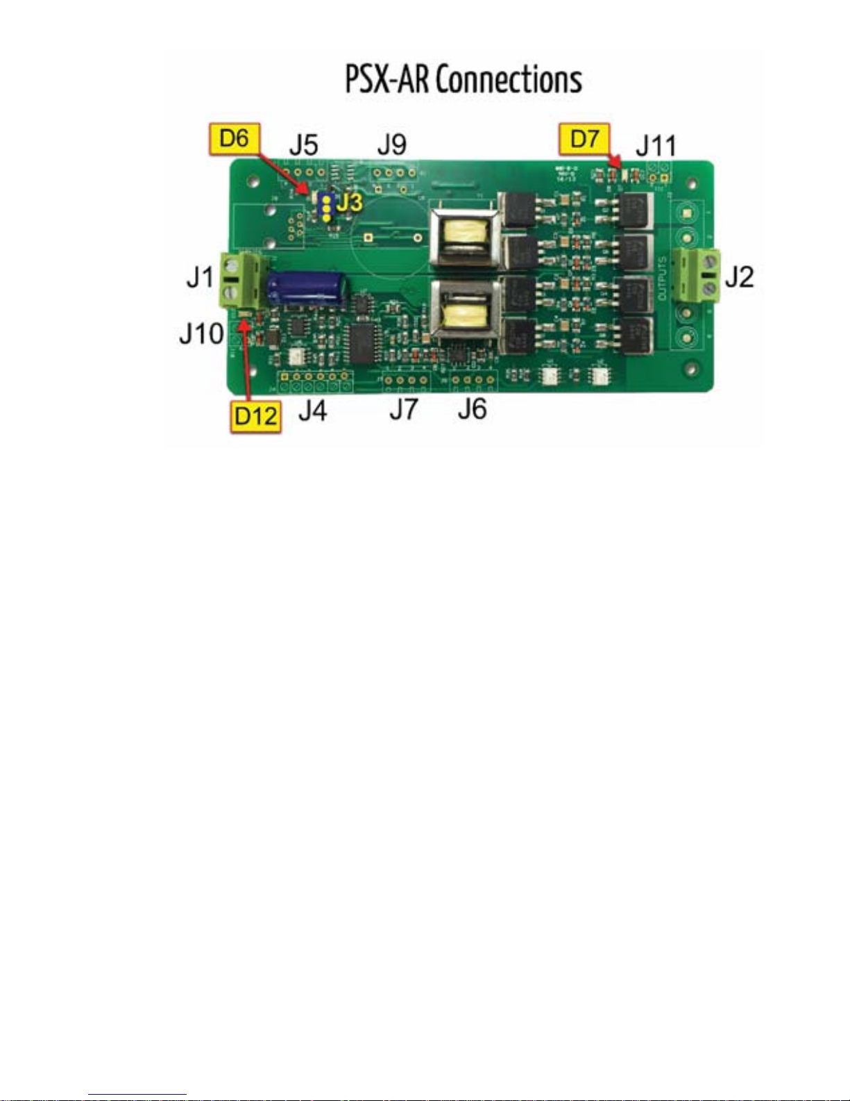
b. The PSX-AR should turn on with both D12 and D7 indicating power and D6 off.
c. Take a piece of wire and connect J1-1 to J2-3. Nothing should change.
d. Connect J1-1 to J2-4. The PSX-AR should reverse and D6 should be slowly flashi ng
with D12 and D7 indicating power.
e. Connect J1-1 to J2-3. The PSX-AR should “unreverse”.
f. D6 should stop flashing, but D12 and D7 should remain on.
g. Repeat this test except connect J1-2 to J2-4.
h. D12 and D7 should remain on, and D6 should be off.
i. Connect J1-2 to J2-3. The PSX-AR should reverse. D12 & D7 are on, with D6 slowly
flashing.
j. Now connect J1-2 to J2-4.
k. The PSX-AR should again “unreverse” leaving D12 & D7 on and D6 off.
l. Verify D7 LED & D12 LED are ON, and the D6 LED is OFF.
Determining the software revision of your PSX-AR: The software revision of the PSX-AR is easily determined.
Simply place the unit in the program mode and turn it on. D6 will flash the Morse code pattern of the software
revision letter. The PSX-AR will flash long-short for revision N.
PSX-AR Manual Rev: P Software Rev: N
4
B. User
Guidelines
1. Before wiring, ensure the Programming Jumper is on pins J3.2 & J3.3 to operate [Pin
J3.1 is nearest the center of the PSX-AR circuit board]
2. Cut isolating gaps in the rails between PSX/PSX-AR zones; stagger gaps 0.75” [21mm]
3. If you are using both PSX circuit breakers and PSX-AR auto reversers on a layout and
the locomotive hesitates when crossing a reverse gap, program the PSX controlling the
track adjacent to the PSX-AR:
a. Program CV55=1 [enable delay]
b. Program CV65=128 [delay=16ms]. CV65 may be any value from 1 to 255. The delay
in milliseconds is the CV65 value divided by 8. Ideally CV65 should be the smallest
value that consistently works correctly. CV65=128 should work for most layouts.
4. Input & Output co nne ctor s J1 and J2 are designed for use with 12-22 AWG wire.
a. Turn screw on connector’s counter-clockwise while looking at the connector opening
b. Make sure the wire clamp is at the bottom of the connector opening.
c. Insert the wire you are connecting and turn the connector screw clockwise to tighten.
5. If you are using a heavier bus wire such as 10 AWG, solder a short length of 12 or 14
AWG wire to your heavier bus to connect to the PSX-AR terminal.
6. We recommend rail drops to the track bus every 3-5 feet. Insufficient feeders can cause
your track voltage to be significantly lower than your booster output voltage.
7. When wiring more than one PSX or PSX-AR [PSX-2, PSX-3 PSX-4, PSX-AR etc.] insure
all input/output polarities are the same
8. The PSX-AR Circuit breaker is designed to operate by openin g both of t he two input lea ds
when an overload is detected.
a. In “normal” polarity (D6 is not flashing), J1-1 is connected to J2-1, J2-3 , J2-5 and J1-
2 is connected to J2-2, J2-4, J2-6. In “reverse” polarity (D6 flashes slowly), J1-1 is
connected to J2-2, J2-4, J2-6 and J1-2 is connec ted to J2-1, J2-3, J2-5.
PSX-AR Manual Rev: P Software Rev: N
5
b. The reverse loop should NOT use a common rail wiring scheme. Both rails must be
isolated from the rest of the layout for the PSX-AR to work properly.
c. If the PSX-AR breaker function activates, J1-1 and J1-2 are disconnected from ALL
J2 connections.
9. Connect the two wires from the DCC Booster to the PSX-AR J1-1 & J1-2 INPUT terminal
10. When Power is applied to the PSX-AR, the D12 LED near the J1 Input and the D7 LED
near the J2 Output should be on.
11. If the D6 LED near the J3 Programming Ju mper is on solid , you may have a shor t between
the two wires from the J2 Output or in the track section.
12. Test the PSX-AR installation prior to running a train:
a. Observe your DCC booster is not shorted.
b. Use a suitable metal object to short the track.
c. The status LED D6 should come on and D7 near the output should be off.
d. Your booster should not trip during this test [D12 stays on].
13. If your booster does trip duri ng this t est [D 12 go es off or flashes on and off], it may not be
able to support automatic reset.
a. Install the Manual Reset ju mper [J7-1 to J7-2] and r epeat the test. Y our booster sho uld
now remain on [D12 stays lit].
b. With the Manual Reset jumper in place, you can reset the PSX-AR by sending an
accessory ON command [check your system manual for correct key sequence] to
accessory address 2042 [997 if you installed the Digitrax Jumper]
c. With the Manual Rest jumper in place, you can also reset the PSX-AR by
connecting a Normally Closed momentary push button in series with the Manual
Reset jumper. Pressing the button will reset the PSX-AR.
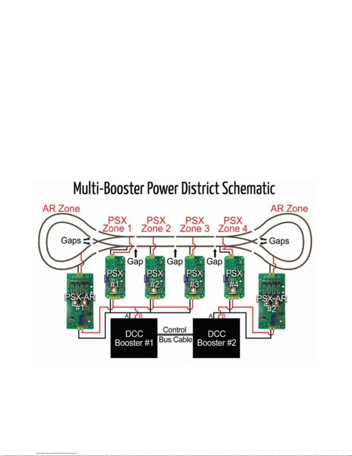
C. How to Determine Power Districts
There are two types of power districts: Single power district per booster or multiple power
districts on a single booster. In either case, y ou want a PSX or PSX-AR protecting ea ch power
district. If you hav e a single booster for a power district, y ou s till want a PSX-1 protect ing that
district. The reason is that the protective circuitry in the booster is designed to protect the
PSX-AR Manual Rev: P Software Rev: N
6
booster, NOT your $1000 fully lit, full sound, decoder equipped, fully detailed scale model.
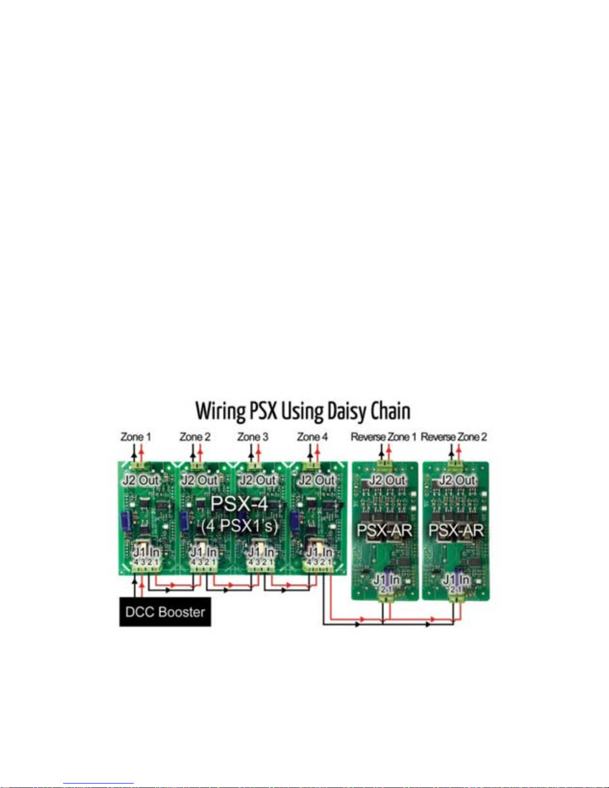
The PSX series IS designed to protect your models. For the multiple power district per
booster, you w ant to use a PSX -2, PSX-3, or PSX 4. Each P SX feeds a district, and the inputs
of the PSX are daisy chained together to a single booster.
Probably the best way to determine where to place power districts is to take a look at the
expected current draw [primarily locomotive motors which use power] for each operating
location on the layout. For example, a busy yard might have several switchers, one or more
trains on the arrival and departure tracks, another train or two passing the yard on the main,
and maybe a peddler lo cal w orking nearby industr ies. If some or all of these tr ains hav e mor e
than one locomotive, you could have 10 to 15 current drawing units all competing for power
in a fairly small area. Assuming all the locomotives have efficient motors, this type of power
requirement [amps] may be large enough to overload a DCC system powered from one 5
Amp booster. For example, if you have four PSX set to the default current, each PSX will trip
at about 4 amperes. If each power district draws 3.5 amperes, that is a total of 14 amperes.
None of the PSX will trip, but your 5 amp booster will certainly shut down. You can solve this
by lowering the trip current on each of the four PSX, getting a booster with a higher current
rating, or splitting the four districts on one booster to two districts on each of two boosters.
Based on our experience, a typical HO scale 5 Amp system can support up to 10 operators
using a 12-14 AWG bus and 20 AWG feeders. Many users overestimate the amount of
Booster power needed. Try using the PSX Series first. If your DCC Booster overloads from
excess current draw, you need to add an extra DCC Booster to support the concentration of
trains in this location. By dividing a layout into power districts in this manner, and using a
combination of booster s and circuit break ers, you can make t he most efficient u se of available
power on any mid-siz e or larg e-size layout.
PSX-AR Manual Rev: P Software Rev: N
7
Another thing you want to keep in mind while designing power districts is how each district is
used. In a yard area, for example, there is a higher risk of derailments occurring with their
associated shorts. You might want to isolate this area into a separate district so that a short
in the yard will not stop mainline operations.
D. PSX-AR Wiring
Wire t o the PSX-AR should be heavy enough to carry the current efficiently. The size of
wire depends on your scale. Too much resistance in the wire or rails can result in faulty
short sensing, voltage drop and poor performance. At a minimum, we recommend the
following stranded gauge wires to prevent potential problems:
• N Scale 18 AWG bus, 22 AWG rail feeders
• HO Scale 14 A WG bus, 20 AWG rail feeders
• O Scale 12 AWG bus, 16 AWG rail feeders
We recommend using stranded pair wire such as speaker or lamp cord wire for bus wiring.
If you’re using two individual stranded wires, make sure to twist the wire 4 to 6 times every
foot. You can make your own twisted pair wire by placing two ends of the wire in a drill bit,
chuck the drill tight, and then turn on while you or something else holds the other end.
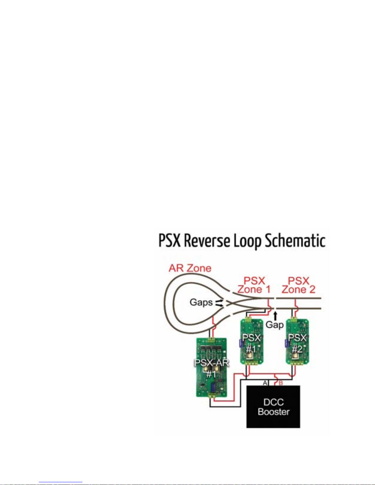
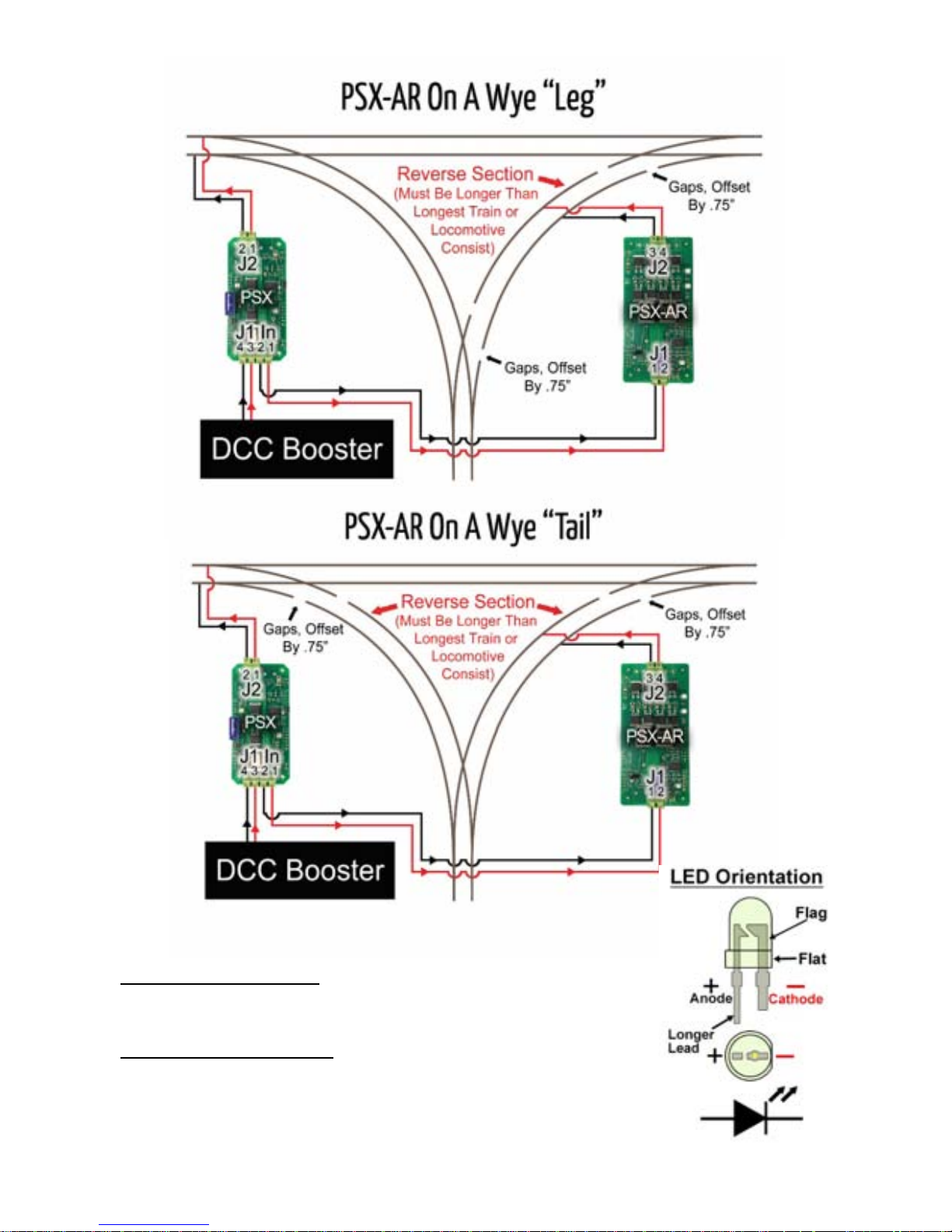
E. PSX-AR Reverse Section Examples
Reverse Section Notes
1) Make sure isolating rail gaps
are offset by 0.75” [21mm] and
the AR Zone is longer than
your longest train
2) If your train is longer than your
reverse block and has met al
wheels:
a) You may need to cut
additional gaps in the
REVERSE SECTION.
b) Simply cut another set of
gaps at BOTH ENDS of
the reverse sections inside
of the original gaps.
c) The distance between new
gaps and original gaps
should be longer than the
wheelbase of any metal
truck.
PSX-AR Manual Rev: P Software Rev: N
8
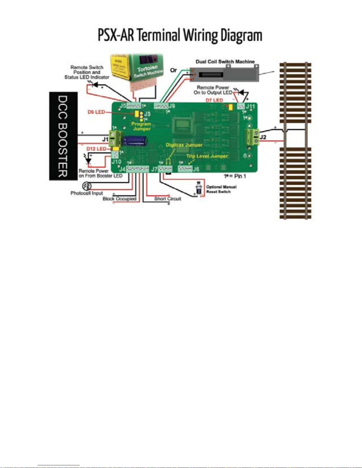
F. Terminal Wiring Descriptions
J1 Input Power Connector
• J1-1 DCC Power Input A [from DCC Booster]
• J1-2 DCC Power Input B [from DCC Booster]
J2 Output Power Connector
• J2-1,3,5 Switched DCC Power Output A [“normal” polarity]
• J2-2,4,6 Switched DCC Power Output B [“normal” polari ty]
• J2-1,3,5 Switched DCC Power Output B [“reverse” polarity]
• J2-2,4,6 Switched DCC Power Output A [“reverse” polarity]
 Loading...