

Page 1
PTT24
Manual
Copyright 2016 All rights reserved.
Manual version 1.0, Firmware version 1.0
All trademarks and trade names are the properties of their respective owners.
Manual Version 1.0, Firmware 1.0
July, 2016
Page 2

TABLE OF CONTENTS
Chapter 1
Introduction............................................................................................1
Package Contents........................................................................................... 2
Software Requirements..................................................................................2
Chapter 2
Installation..............................................................................................3
Overview................................................................................................... 3
Installation and Configuration...................................................................... 4
1. Rack Mounting ...........................................................................................4
2. Cabling........................................................................................................ 4
12 and 24 Port cable reference.................................................................. 5
3. Select 12 or 24 ports................................................................................... 6
4. Chassis grounding...................................................................................... 6
5. Power connections......................................................................................7
6. Alarm connections ..................................................................................... 7
7. Select control channel................................................................................ 7
8. Push button test......................................................................................... 8
Chapter 3
Testing...................................................................................................... 9
Overview......................................................................................................... 9
Field Testing...................................................................................................9
Appendix A
Specifications.......................................................................................... 10
Specifications............................................................................................10
ii
Page 3

Chapter 1
Introduction
This chapter provides an overview of features and capabilities.
he PTT24 is a Push-to-Talk lockout device. It is used with multiple E&M circuits linked to
radio transmitters, PBXs, etc. The PTT-24 solves the problem of E&M leads being locked
T
into a Transmit ON state when a T1 circuit fails. Many T1 trunk lines will go into a busy
condition when the T1 trunk fails. This causes the E&M leads to lock in an ON state, which
causes radio transmitters to lock in the ON state, tie lines to go off hook, etc.
12 or 24 E&M ports are wired through the PTT Lockout unit. A front panel toggle
switch is used to select 12 or 24 port operation. A 2 digit push button switch is used to select
the E&M DS0 control channel. The Power LED flashes if an invalid control channel number
is selected.
Based on the selected E&M DS0 control channel (via the front panel) the PTT
Lockout device will detect a closure to ground on that channel and de-assert all the other
channels. E&M Type III is not supported.
In the PTT-24 12 channel mode, selecting control channel 1 through 12 will select one
of the even numbered leads 26 though 48 as the control channel. The other 11 even
numbered leads will be de-asserted if the control channel is asserted. All other leads are
passed straight through.
In the PTT-24 24 channel mode, selecting control channel 1 through 24 will select one
of the leads 26 though 49 as the control channel. The other 23 leads will be de-asserted if the
control channel is asserted. All other leads are passed straight through.
If the PTT-24 were to lose power, the E-leads will be in a pass through mode as
though the PTT-24 is only a “lump in the cable”.
Lockout can be triggered by the E&M control channel being activated or the alarm
input. For both the control channel and the alarm input, there is a delay of 20 milliseconds
before the lockout occurs. The de-activation delay is 5 seconds. The de-activation delay
eliminates lockout “chattering” on/off/on/off, etc.
Leads 1 through 24 and 50 of the 50 pin Amphenol telco connectors are passed
straight through from the channel bank to the transmitter. The PTT24 does not impact these
leads in any way.
1
Page 4

Package Contents
You should find the following items packaged with your PTT24:
The PTT24 rack mount unit with power and alarm connectors
4 plastic cable tie mounts and 4 4-40 x 1/4” screws
2 filler spacers used under the 4 #10-32 x 3/8” panel mount fasteners
Manual
Optional: 1 - 9802012 PC Direct adapter, 1 – 9500023 green network management
cable
Software Requirements
Except for testing there is no need for any software to configure or operate the PTT24. Using
the PTT24 RS232 port requires removing the top cover to access the management port
located inside the unit. Except for testing it should never be necessary to access this port in
the field.
To use the RS232 port, use the supplied green network management cable (6500023) and the
PC direct adapter (9802012) to connect to a terminal or PC. The management port is 9600
bps, 8 data bits, no parity. No special terminal type is required. Either a “dumb terminal
mode” or a VT terminal type should suffice. Hypterterm, TeraTerm, Putty are examples of
suitable terminal software.
2
Page 5

PTT24 Manual
Chapter 2
Installation
This Chapter details the installation process .
Overview
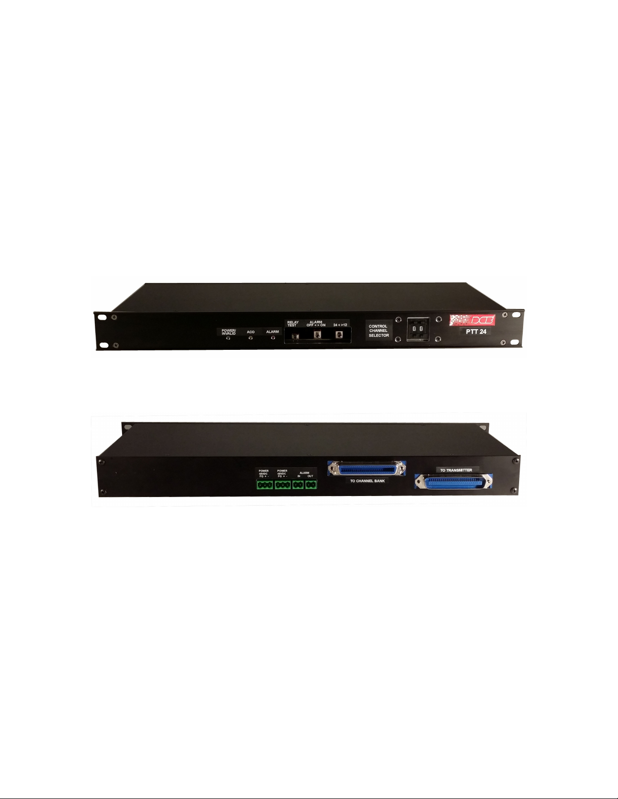
The PTT24 is a 1U high by 19” rack mount unit. Installation and configuration of the PTT24
PTT24 Front Panel
PTT24 Rear Panel
3
Page 6

Installation: Channel Bank, Transmitter, Power, Alarm, Ground
1. Rack mount the PTT24
The PTT24 is shipped with 4 mounting screws and 2 rectangular spacers. The spacers protect
front panel from being bent or scratched by the mounting screws.
2. Cable the Channel Bank to the PTT24
Standard straight through 50-pin male to female telco cables are used to connect to the
PTT24. The PTT24 wiring path is designed to work with the Charles Industries 360 series
channel banks. Wiring charts for 12 and 24 ports are shown below on the follow page for
reference.
4
Page 7

Controlled and Pass Thru Channels for the 12 and 24 Channel Selections
PTT24 Manual
5
Page 8

3. Select 12 or 24 Channel Operation
The toggle switch “24< >12” selects either 12 or 24 channels of E&M leads to be controlled by
the PTT24. The left position selects 24 channels, the right position selects 12 channels.
4. Connect the PTT24 Frame/Chassis Ground
Frame ground is on the 48 VDC power connectors, on the 50-pin telco connector shells and
cable tie down screws.
6
Page 9

PTT24 Manual
5. Connect the PTT24 to 48 VDC Power
Each PTT24 has 2 diode protected power connectors. The power connectors are 3 position
Phoenix type connectors. Each connector has Frame Ground, positive and negative power
connections.
6. Connect the Alarm IN and Alarm Out
The Alarm In can come from another PTT24 or from the channel bank. The Alarm Out can
be connected to another PTT24, to a SCADA system for remote reporting, to some local
external alarm signal device, etc. The Alarm In and Alarm out are contact closures. Alarm
Off is open, Alarm On is a closed relay connection. The PTT24 will operate with or without
the Alarm In or Alarm Out connected.
7. Select the Control Channel
Select the Control Channel to be monitored by the PTT24. For 12 channel operation the
channel must be from 1 to 12. For 24 channel operation the channel must be from 1 to 24.
The Power LED will flash if an invalid channel is selected. .
7
Page 10

8. Relay Test Push Button Switch
The PTT24 Relay Test switch can be pressed for a quick test. The audible alarm should
sound, relays should click, the Alarm LED should light, the Alarm Out relay should operate.
The alarm will sound only when the ALARM toggle switch is in the ON position.
8
Page 11

PTT24 Manual
Chapter 3
Testing
Overview
The PTT24 has a front panel test switch, Channel Selector Switch for the Guard Channel,
Audible Alarm, and LEDs. The PTT24 has rear panel Alarm IN and Alarm OUT connectors.
The PTT24 has an internal RS232 test port. A factory test assembly is used during
manufacturing for final testing of the PTT24. Most of the PTT24 functionality can be checked
in the field. The following outlines the testing that can be done in the field. The factory test
procedures are also noted. The factory test assembly can be purchased for customer field use.
Field Testing
Front Panel Test Switch
Pressing the front panel test switch will enable all the relays, sound the audible alarm, light
the Alarm LED, cause the Alarm Out leads to close and all the relays will operate. The
sound of the relays operating can be heard as a low level clicking sound. The alarm will
sound only when the ALARM toggle switch is in the ON position.
Alarm In and Alarm Out
To test the Alarm In, the 2 leads on the Alarm In connector can be shorted together. When
shorted, the ALARM LED will light, the audible alarm will sound (if not disabled by the front
panel switch) and all the relays will operate. The Alarm Out can be checked with a VOM.
When the the Relay Test button is pushed the Alarm Out leads will be closed.
Channel Selector Switch and Power LED
The channel selector switch can be set to an invalid channel number. This will cause the
Power LED to flash.
Audible Alarm
With the Alarm Cutoff Switch set to ON, pressing the Test Switch will cause the audible
alarm to sound. Also, shorting the Alarm In leads will cause the audible alarm to sound. If
the alarm is activated with the Alarm Cutoff Switch set to OFF, no audible alarm will sound.
LEDs
The LEDs are Power/Invalid Channel, ACO and Alarm. The Power LED is on when power is
applied to the PTT24. The Power LED will flash if an invalid control channel is selected. An
invalid channel is any except 1 through 12 when 12 channels are selected via the front panel
switch. An invalid channel is any except 1 through 24 when the 24 channels are selected via
the front panel switch.
RS232 Port
The PTT24 has an internal RS232 port located on the right hand side of the PC board when
viewed from the front. To access the RS232 port the cover of the PTT24 must be removed.
The RS232 port is an RJ45 connector. A special Network Management cable and RJ45 to
DE-9 female connector is available for using this RS232 port. See the next section for details
on the operation of the RS232 port.
9
Page 12

Appendix A
Specifications
PTT24 Push-to-Talk Lockout Device Specifications
General
• Front Panel (these are approximate placements, subject to relocation):
- Toggle switch to select 12 or 24 E&M ports
- Push button switch to select port 1 to 24 for PTT Lockout control
• - Test switch, momentary, to test lockout function
- Front panel switch to kill an audio alarm that will sound when/if the control port activates
- Green Power LED (flashes if an invalid control port number is selected, i.e. 00, 25, etc.)
- Red "ALARM" LED to indicate the PTT Lockout switch is activated
• - Yellow "ACO" LED to indicate the ALARM CUT OFF is on
• Rear Panel
• - 2 rear panel power inputs for -48 VDC power, diode protected between the 2 power inputs
to avoid power feed back
• - Alarm Input (dry contact closure) to externally activate the PTT Lockout function and/or
test the unit
• - Alarm output dry contact
• - Female 50 pin telco connector from the channel bank, screw connection and cable tie type
of cable cable fasteners
• - Male 50 pin telco from the PTT lockout to Transmitter side of the circuit, screw connection
and cable tie type of cable fasteners
Physical/Electrical
• Standalone or rack mounting
• Power requirements: -48 VDC
• 19” W x 10” D x 1 ¾” H
• 3 pounds
Environmental
• Operational Temperature: -40 to +70 C
• Storage Temperature: -50 to +75 C
• Humidity: <95% Non-condensing
10
 Loading...