

Page 1

PR-6606
Packet Replicator
User’s Guide
Copyright 2018 Data Comm for Business, All rights reserved. Revised Feb 2, 2018
Firmware Version 2.x
Page 2

Certications
FCC Statement
This device complies with the limits for a Class A digital device, pursuant to Part 15 of the FCC rules.
This equipment has been tested and found to comply with the limits for a Class A digital device pursuant to
Part 15 of the FCC Rules. These limits are designed to provide reasonable protection against harmful
interference when the equipment is operated in a commercial environment. This equipment generates, uses,
and can radiate radio frequency energy and if not installed and used in accordance with the instruction
manual may cause harmful interference to radio communications.
Operation of this equipment in a residential area is likely to cause harmful interference, in which case the
user will be required to correct the interference at the user's own expense.
RoHS
Some models of this product are available in RoHS versions.
Copyright 2018 Data Comm for Business, Inc. All rights reserved.
Page 3

TABLE OF CONTENTS
Certifications...............................................................i
FCC Statement.........................................................i
RoHS.......................................................................i
Chapter 1
Introduction................................................................4
PR-6606 Applications..................................................4
Features........................................................................ 5
Other Protocols.........................................................5
DHCP Protocol..........................................................5
Extensive Packet Selection Rules..............................5
Upgradeable Firmware..............................................5
Security Features......................................................5
On-board Tools..........................................................5
Installation Location..................................................5
Package Contents......................................................... 5
Software Requirements..........................................6
PR-6606 Hardware......................................................7
Introduction........................................................... 7
Configuration ....................................................... 7
Rear Panel LED Indicators ....................................7
Rear Panel USB Connectors..................................7
Rear Panel RS-232 Connector............................... 7
Rear Panel Ethernet Connectors.............................7
Front Panel LED Indicators..................................7
Chapter 2
Installation..................................................................9
Overview.....................................................................9
Help Screens and Field Edits........................................9
Installation and Configuration..................................... 9
1. Configure the IP address......................................9
2.Connect the Ethernet Cable..................................11
3.Verify the IP Address Configuration.....................11
4. Enter Configuration Values .................................12
5. Minimum Configuration......................................12
Chapter 3
The Configuration Process.........................................13
Overview.....................................................................13
Using the Configuration Flexibility..............................13
Configuration Process Examples .................................14
Example 1: ............................................................14
Example 2:...............................................................14
Example 3:...............................................................14
i
Page 4

Saved Configuration Files........................................14
Chapter 4
Configuration..............................................................15
Overview.....................................................................15
Administration............................................................. 15
Admin Password..........................................................16
Fields.......................................................................16
Notes........................................................................ 17
Admin Access Control..................................................17
Fields.......................................................................17
Notes........................................................................ 18
Set Clock..................................................................... 19
Fields.......................................................................19
Notes........................................................................ 19
Set Name..................................................................... 20
Fields.......................................................................20
Notes........................................................................ 20
Set All Defaults............................................................21
Configuration File........................................................22
Fields.......................................................................22
Notes........................................................................ 22
Firmware Upgrade.......................................................23
Fields.......................................................................23
Notes........................................................................ 23
System Reboot.............................................................24
Fields.......................................................................24
Notes........................................................................ 24
Version Information Screen..........................................25
LAN IP Configuration..................................................26
Fields .....................................................................26
Replication Selection Rules..........................................28
Fields.......................................................................29
Replication Rules Destinations Screen.........................30
Fields.......................................................................31
Notes........................................................................ 31
Ping Screen................................................................. 32
Fields.......................................................................32
Notes........................................................................ 32
Traceroute Screen........................................................ 33
Fields.......................................................................33
Notes........................................................................ 33
Packet Sniffer Screen...................................................34
Fields.......................................................................34
Notes........................................................................ 34
Interface Status Screen................................................ 35
Replication Log Screen...............................................36
Replication Statistics Screen.......................................37
ii
Page 5

Routing Table Screen..................................................38
DHCP Status Screen.....................................................39
Store Configuration Screen.........................................40
Activate Configuration Screen....................................41
Chapter 5
Operation ...................................................................42
Common Uses – Overview ..........................................42
Typical Application Diagrams .....................................42
Chapter 6
Troubleshooting..........................................................43
Hardware Problems...................................................... 43
Can't Connect via the LAN...........................................43
Other Problems............................................................ 44
Appendix A
Specifications..............................................................45
PR-6606 Packet Replicator Specifications....................45
Cables.......................................................................... 45
PR-6606 to hub or ethernet switch.....................45
PR-6606 to PC crossover ethernet cable............45
Introduction
Appendix B
Open Source Software Information...........................46
Introduction........................................................... 46
Obtaining the Source Code....................................46
iii
Page 6

Chapter 1
Introduction
This chapter provides an overview of the Packet Replicator’s features and capabilities.
ongratulations on the purchase of your new EtherSeries PR-6606. This is a simple, easily configured
C
packet replicating device containing three Ethernet interfaces.
The PR-6606 replicates UDP packets through any IP network. The PR-6606 has three Ethernet LAN ports
and a serial port. The Ethernet ports are 10/100/1000 BaseT, copper, MDI/MDIX auto-sensing. The serial
port is used for initial setup to configure the IP address.
The PR-6606 duplicates some or all of the UDP packets passing through it. The original packet is passed
unchanged; if selected for duplication, it is duplicated and the duplicates sent to configured addresses.
All UDP packets are candidates for duplication, selected based upon configured criteria. The selection of a
packet to be duplicated may be based upon any combination of the source IP address, the destination
address, and UDP port number. Additional flexibility is provided with the selection criteria which may
include multiple address ranges for the source, destination as well as UDP port selected.
Each packet selected by one of the five selection rules may be duplicated to as many as ten recipient IP
addresses. UDP port numbers may be passed intact with no change to the destination port number, or to a
different UDP port number substituted for the original one.
The PR-6606 is bidirectional. Packets being returned through the PR-6606 may be passed unchanged, or
duplicated according to duplication rules.
As all UDP packets are candidates for selection, the PR-6606 may be used to duplicate SNMP, NTP,
SCADA protocols including DNP/UDP, and MODBUS/UDP, as well as all other UDP packets.
The PR-6606 is managed via web browser.
PR-6606 Applications
The PR-6606 is in used SCADA, SNMP, netflow, streaming video, streaming audio, and other applications
where it is useful to have a single device send duplicate data streams to multiple devices. In short, may be
applied any time a single UDP packet needs to be duplicated.
Since the packets from the PR-6606 appear to be sent from the originating device, any responses to those
packets will be returned to the originating device. This back-path is without any action by the PR-6606.
In installations where multicast packets are required and only a unicast path is available, the PR-6606 can
translate multicast UDP addressing to unicast UDP addresses in a bidirectional operation.
4
Page 7

Conguration
Features
Other Protocols
The PR-6606 operates only on UDP/IP packets. All other protocols are passed through the device
unchanged.
DHCP Protocol
The PR-6606 may be configured as a DHCP client.
Extensive Packet Selection Rules
User defined selection criteria is configured in "rules". Each rule allows packets to be selected based upon
source IP address, destination IP address, and destination IP port number. IP address and port entries may be
a single value such as one IP address (192.168.2.2 for example) or one port number (for example 3001) or a
range such as 192.168.1.2 to 192.168.1.230 or port 5001 through 8000. If no port number is entered, all
UDP packets meeting other selection criteria are duplicated. To insure the PR-6606 will replicate the
desired packets, the PR-6606 must be inserted in the network path between the original packet's source and
original packet's destination. Furthermore, to prevent MAC table corruption in any layer-2 switches, the
destination of a replicated packet must also reside on a different LAN port from the original source. To
summarize, the original source cannot be located on the same PR-6606 LAN port as the original destination
or replicated destination.
Upgradeable Firmware
Firmware upgrades may be installed using any web browser.
Security Features
The web interface used to configure the PR-6606 may be secured using HTTPS SSL. The secure web
server operates using the SSL protocol which allows for the use of x509 certificates to identify and
authenticate web servers and web browsers. You may generate a pair of x509 certificates within the
PR-6606 or import certificates from your external certificate authority.
On-board Tools
The PR-6606 contains diagnostic tools such as extensive logging, statistics, traceroute, ping, and a simple
packet sniffer to aid in network troubleshooting.
Installation Location
To insure the PR-6606 will replicate the desired packets, the PR-6606 must be inserted in the network path
between the original packet's source and original packet's destination. Furthermore, to prevent MAC table
corruption in any layer-2 switches, the destination of a replicated packet must also reside on a different
LAN port from the original source. To summarize, the original source cannot be located on the same
PR-6606 LAN port as the original destination or replicated destination.
Package Contents
You should find the following items in the package:
The PR-6606
Power Adapter
This User’s Guide CDROM
9-pin Remote-PC adapter (Units with serial ports only)
If any of the above are missing, contact your dealer immediately.
5
Page 8

Software Requirements
The PR-6606 replicated only UDP/IP packets. It also bridges any valid Ethernet protocol between it's
Ethernet ports, similarly to a switch. The initial IP address may be entered using any terminal or
terminal emulation software on a PC, or the default may be used if appropriate for your network.
Any standard web browser may be used for configuration once the PR-6606 is configured with a valid IP
address.
6
Page 9
Conguration
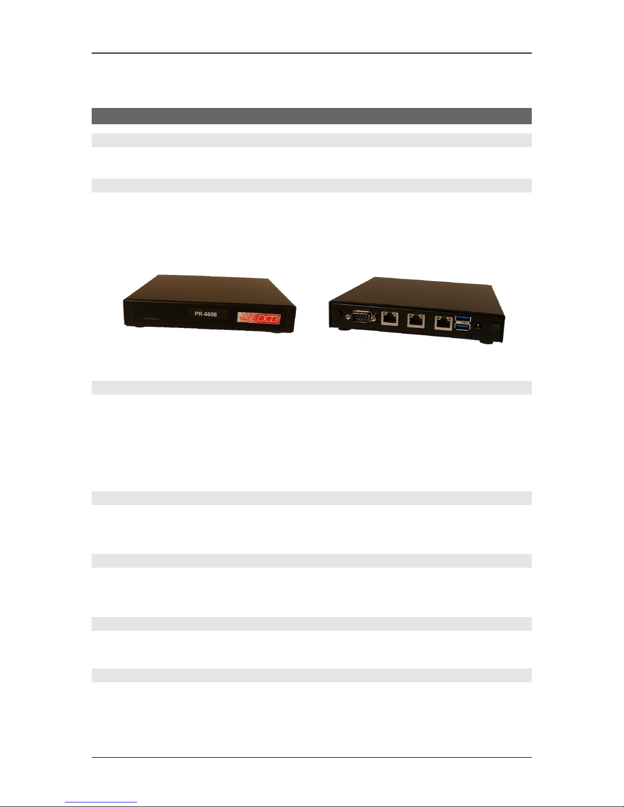
PR-6606 Hardware
Introduction
The PR-6606 three Ethernet ports and two USB ports. There is also a RS-232 serial port used for initial IP
address configuration (if needed).
Configuration
This model contains a serial interface to be used in initial setup (if needed). IF the default IP address is not
appropriate for your LAN, connect a terminal to the serial port following the instructions in the
configuration section. The setup port is always active. Follow the command line setup instructions to
configure a compatible IP address. Once a compatible IP address is available, the browser setup screens are
used to complete the unit's configuration.
PR-6606 Front PR-6606 Rear
Rear Panel LED Indicators
One set of indicators For Each Ethernet Port
The green LED to the left of each Ethernet port is a LAN activity indicator. This LED flashes with
activity on the Ethernet (even if the activity isn't directly to this unit).
The yellow/green LED to the right of each Ethernet port is the Ethernet Status indicator. It is lit amber
when the port is connected to a 1000BaseT switch, green for 100BaseT. It is not lit for 10BaseT
connections.
Rear Panel USB Connectors
There are two USB connectors. They are interchangeable, and only the first one that senses a USB device
connection is activated. These are only used for transferring certificate files.
Rear Panel RS-232 Connector
The DE-9 (PC 9-pin) connector is used for command line setup. A cross-over cable is required to use this
with any standard PC serial port. Terminal configuration is 9600 bps, 8N1 .
Rear Panel Ethernet Connectors
The three 10/100/1000 BaseT connectors are auto-sensing and share the same IP address.
Front Panel LED Indicators
Power indicator. It should be on.
7
Page 10

Chapter 2
Installation
This Chapter details the installation process for the PR-6606.
Overview
The PR-6606 is configured using a web browser directed to its address. If the default address of
192.168.0.1 is appropriate for your local network, then plug it in and simply direct your web browser to the
PR-6606 (using https if you've configured it to use https, otherwise use http:) without using a proxy and
continue with configuration. If this address is not appropriate for your network, the IP address must be
configured using the initial terminal method below.
Help Screens and Field Edits
The field names on all configuration screens are hyperlinks to context sensitive help screens. Simply click
on the field name to bring up a second window with the help information. Close that window to return to
your entry screen.
Entries are always tested for valid values. However, there are many “valid” values that are not appropriate
for any given configuration. So, “appropriateness” isn’t tested. For example, an IP address of
300.400.500.256 will not be accepted, but the field will accept an IP address that is not appropriate for
your installation.
Installation and Configuration
1. Configure the IP address
If the default address (192.168.0.1) is appropriate for your network, skip to step 2, “Connect the
Ethernet Cable”.
1. Connect a terminal or PC running terminal emulation program (Hyperterm, Procomm, etc) to the serial
port.
2. Start the terminal emulation program using 9600 bps, 8-bits, No parity, No flow control.
3. Power up the unit.
Welcome to the PR-6606 v2.00
To start the Setup Program, login with
the name: setup
PR-6606 login:
8
Login Screen
Page 11

Conguration
4. It will reboot pausing at a login screen. For initial setup, enter the login name “setup” in lower
case letters. No password is required.
5. You will then be asked if you wish to set ALL parameters to factory defaults. If you have previously
changed any values and want to return to the factory defaults, answer “Y”, otherwise answer “N”.
-------- PR-6606 Setup Program --------
Welcome to Setup. This setup will establish the PR-6606 in
a known state so that you can configure it via a Web Browser.
It will allow you to configure the Ethernet IP address
subnet mask, and gateway. You also have the option to set all
parameters to default, which is the only method to remove
security parameters.
HTTP port: 80
LAN1 Configuration:
IP: 192.168.1.56
SM: 255.255.255.0
GW:
Set ALL parameters to default (y/[n])?
Default Screen
6.You are then asked if you wish to configure the unit as a DHCP client. If you want it to pick up a DHCP
address from a local DHCP server connected to LAN1, answer “y”, otherwise answer “n”.
Should LAN1 use DHCP to get an IP address (y/[n])? n
DHCP Screen
7. If you answered no to that question, you will be prompted to enter the unit’s IP address and subnet
mask. Enter the values. Note that all three ports share the same IP address.
8. The configuration is now saved to flash memory. Do not cycle power during this time or the unit may
be rendered inoperable.
Saving Configuration. Do not cycle power...
Setup complete.
After rebooting the system, you will be able to configure
the unit from a Web Browser. Use the URL
http://11.22.33.44
rebooting system. .
9. The PR-6606 will now reboot.
9
Page 12
2. Connect the Ethernet Cable
Connect a LAN cable from your hub or switch to a LAN port. Reboot with a power cycle. The PR-6606
will now be available to any web browser on the same LAN segment. If your web browser does not see it,
verify that you do not have a proxy server configured in the browser and are using https instead of http for
a secure connection IF you've already changed the unit to HTTPS. If so, properly configure the browser to
bypass the proxy server for this URL. The default address is 192.168.0.1. This address must be
appropriate for your local LAN and workstation, or step 1 above must be followed.
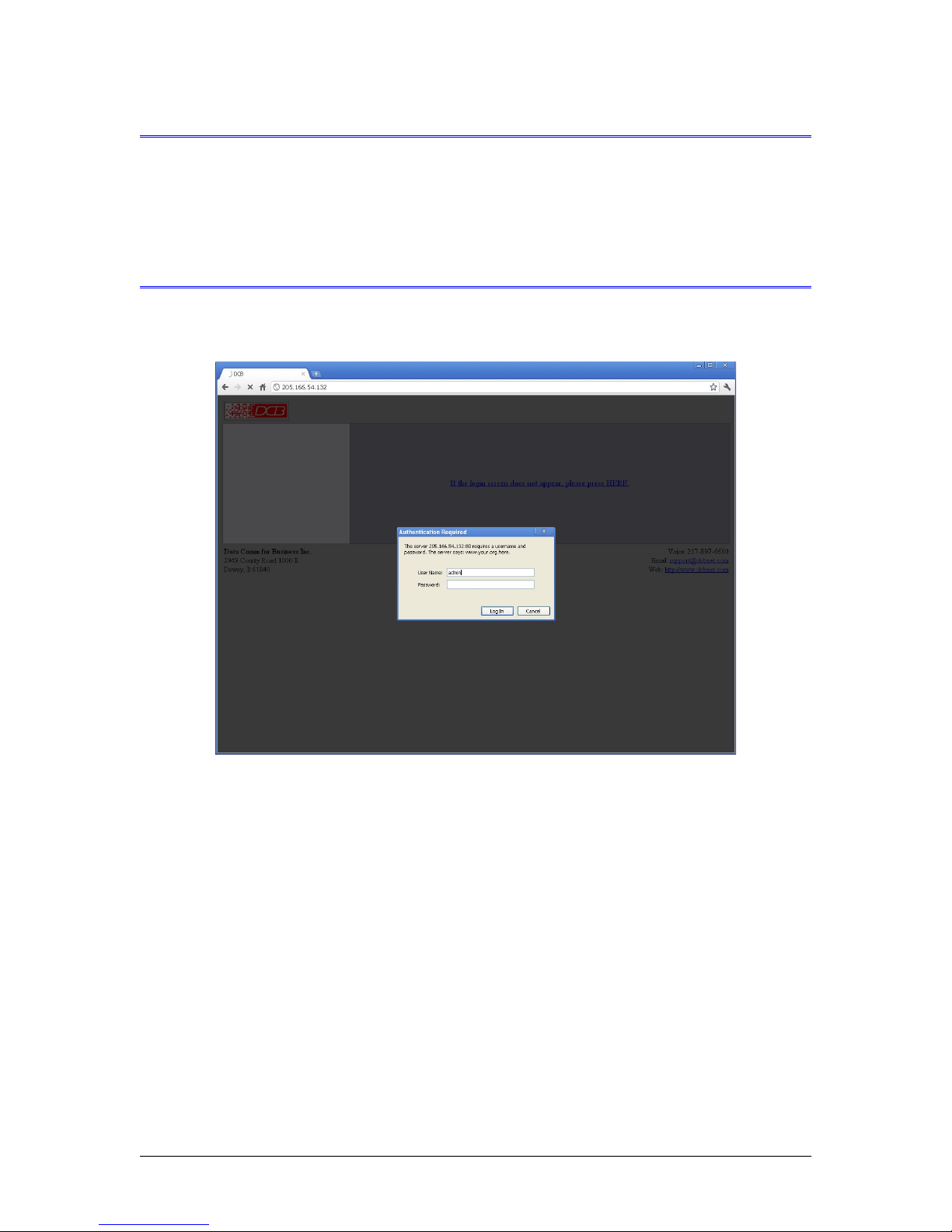
3. Verify the IP Address Configuration
Enter the URL from step 1 (or http://192.168.0.1 if using the default address ) into your web browser. The
login screen below should be displayed.
Log in using the user name “admin” and no password (blank field). If this screen doesn’t display, check
the Troubleshooting Section in Chapter 6.
10
Login Screen
Page 13
Conguration
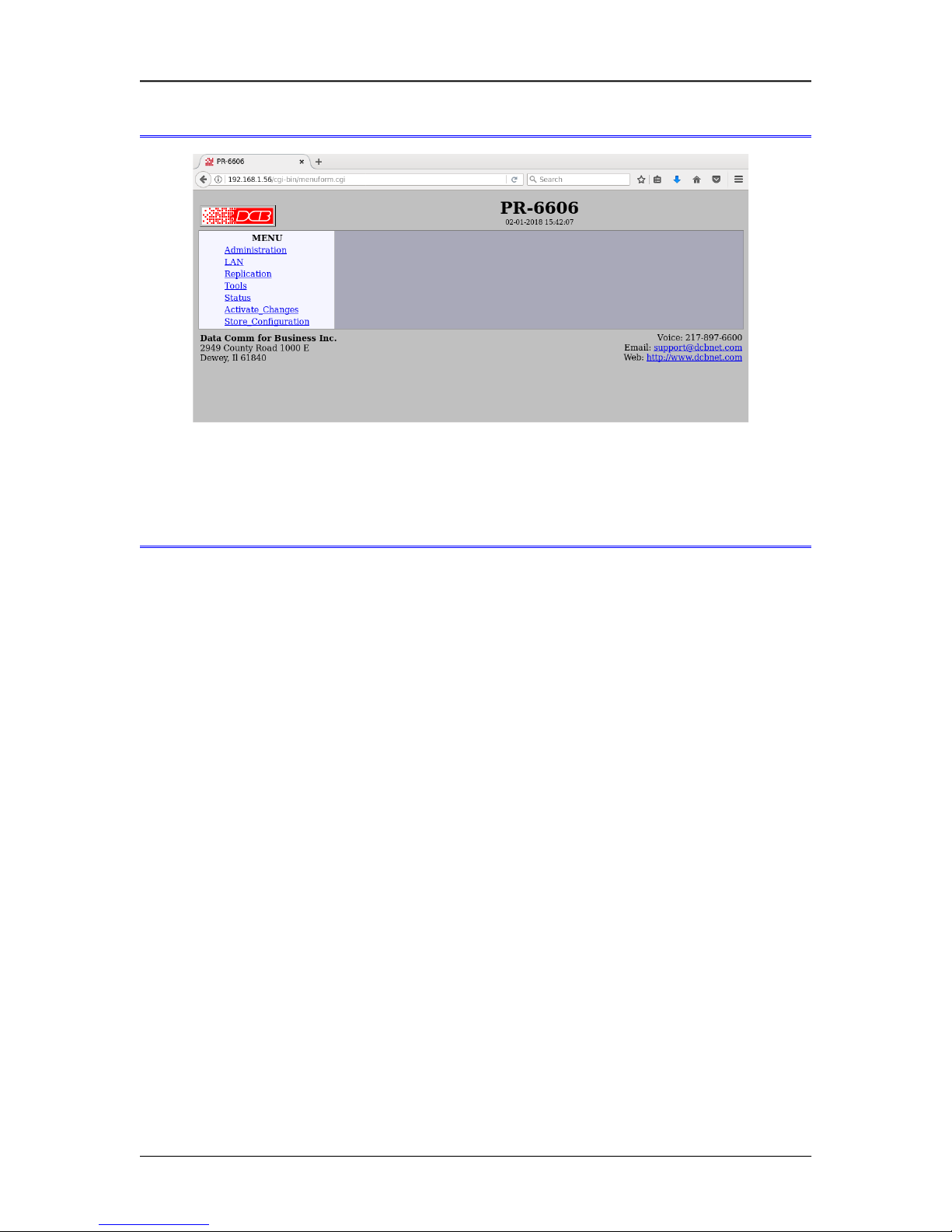
4. Enter Configuration Values
Initial Main Menu
From this index screen, you can select a section on the left and will be taken to configuration screens for
each subsystem. You must enter configuration values specific to your installation.
5. Minimum Configuration
The minimum configuration items required for basic packet replication are:
1. Correct IP address configuration, includes either DHCP or IP address, Gateway, and Netmask.
2. At least one packet replication selection rule.
3. At least one destination detail screen for the packet replication rule
Configure these items using the LAN Configuration and Replication Rule screens and the PR-6606 is ready
for use.
11
Page 14

Chapter 3
The Conguration Process
This Chapter describes the configuration management process on the PR-6606 using a
Web Browser.
Overview
The PR-6606 contains a quite flexible configuration management system. By using this system correctly,
one can remotely configure, save copies of that configuration to a PC, make configuration changes for later
activation, and remote transfer firmware upgrades to the unit.
There may be up to three configuration “images” in use at any time.
1. The active configuration. Normally, this is the configuration that was loaded from memory when the
unit was last booted. However it may have been changed since boot time as described below. This is
the configuration that is currently running the unit.
2. The pending configuration: This is the current configuration that was loaded form memory during the
last boot along with any changes made by using the configuration screens. This configuration is
NOT the configuration running the PR-6606 at present.
3. The stored configuration. This is the configuration that was last written to the non-volatile RAM. The
next time the PR-6606 is power cycled, it will start running this configuration.
Note that any configuration transfer (with the Administration Configuration Transfer screen) is the pending
configuration. You can load a configuration file from the PC, then either activate it to test it. Or, save it
without activation if you don’t want to change the currently running configuration.
Using the Configuration Flexibility
When the PR-6606 starts from a power-off condition, it loads an active configuration from its non-volatile
memory. This active configuration is also copied to the working memory and is the “pending”
configuration.
Whenever the configuration screens are used to change values, only the pending configuration is
changed… not the active configuration.
Using the configuration screens will change the pending configuration. You may change the active
configuration by copying the pending configuration over it. This change is performed using the “Activate
Configuration” screen. Going to this screen activates the pending configuration by copying the pending
configuration over the top of the active configuration. This does not store the configuration in non-volatile
memory. When the hardware is next reset or powered up, it will begin using the old stored configuration
from before the changes were made and activate command clicked.
Using the “store configuration” screen will copy the pending configuration into non-volatile memory. It
will not cause this configuration to begin running. However, upon the next reset or power cycle, the
PR-6606 will begin using the stored configuration.
It is possible to activate the pending configuration using the Activate Configuration screen and then store
the configuration using the Store Configuration screen. This two step process will cause all three
configurations to be identical.
12
Page 15

Conguration
Configuration Process Examples
Example 1:
Make configuration changes, test them with Activate, then save them with Save.
This is the most commonly used method for changing the configuration. It allows you to test the
configuration prior to saving it. If, during the testing, you notice an abnormality; you can reset the
hardware to return to the last good configuration.
Example 2:.
Make configuration changes, save them, reset the hardware to activate the changes.
This method allows one to configure thePR-6606 via an IP network that will not work using the new
configuration. Make the changes to the pending configuration and save them. Your current session will not
be affected, but when the hardware is next powered on, it will begin using the new configuration. This
method is useful when you are configuring to use a new LAN address range while still on the old LAN.
Example 3:
Transfer a saved configuration, save it, reset the hardware to activate the changes.
It is useful to transfer an existing configuration to a PC text file for future use. Then if the hardware must
be replaced, simply transfer that stored configuration to the new hardware.
If the PC is in the default IP address range of the new hardware (192.168.0.x subnet), then a new,
out-of-the-box unit is easily configured using this method. Start the hardware on the LAN, transfer a
stored configuration file from the PC, and store it. When restarted, the PR-6606 will have the proper
configuration.
Saved Configuration Files
The saved configuration file is a simply formatted raw text file. Advanced users may wish to edit this file
using an appropriate text editor, then transfer the changed configuration to a different unit.
Use care when performing configuration with this technique as the text configuration file must be in the
proper format.
This method is ideal for automating the configuration of many units in a large corporate environment.
13
Page 16

Chapter 4
Conguration
This Chapter describes configuration screens and some configuration hints for the
PR-6606
Overview
The PR-6606 is configured using forms displayed on a web browser. In this chapter, we illustrate all entry
forms, and describe their use.
All configuration screens are accessed from the main index screen shown below. They are divided into
sections with only one layer of screens below the top level.
Some units may be configured to require a secure web browser connection for configuration (https:// )
PR-6606 Main Screen
From this index, click on a menu keyword to open the appropriate screen. In this manual, screens are
discussed in the order shown on the index screen.
Administration
The Administration section contains screens used to configure system-wide settings and perform a few high
level operations.
14
Page 17

Admin Password
Conguration
Admin Password Screen
Access to the configuration web server is protected by HTTP Basic Authentication and may use a
secure web server. This is a simple methodology where the Web Server will require a Web Browser to
provide a username and password for each page requested. The Web Browser will typically ask the
user to enter the username and password once, then will remember it for the duration that the Web
Browser is running. For some configurations, use https: (instead of http: ) when addressing web
browser screens.
The Administration screen allows you to change the user name and password for the administrator.
This is the only user allowed to configure the unit. If you forget the administrator name or
password, the hardware can only be configured by returning it to factory defaults as described in
the quick start chapter.
Fields
User Name
This field may be a string of 0 to 15 printable characters. Do not use space or control characters. If you
leave this field blank, you will need to enter a blank username during authentication.
Old Password
In order to change the username and password, you must know the old password. When making a
change, enter the current password in this field.
New Password
When changing the username and password, this field provides the new password. It may be a string
of 0 to 15 characters. If you leave this field blank, you will need to enter a blank password during
authentication.
Verify New Password
Retype the password to verify that it was correctly entered.
15
Page 18

Notes
If you forget your username or password, you can use the Serial Port Setup to erase the current
settings and return the unit to factory defaults.
Admin Access Control
Administrative Access Control Screen
Access Control allows you to place further restrictions on access to the internal web server.
Fields
Web Server Port
This is the TCP Port to use for the internal Web Server. Typically it is set to port 80. However you
may set it to any value between 1 and 65535.
There are several reasons that you may want to change the web server port. By changing it to a
non-standard value, you reduce the chance that a random attacker will find the web interface and
attempt to break in. A different port may be needed to accommodate local firewalling.
If you change the web server port number to any value other that 80, remember that you will have to
include the port number in your URL. For example, https://192.168.0.1:7995 OR
http://192.168.0.1:7995 .
Require Certificates
This option enables certificate based authentication of web browsers attempting to connect to the
internal web server. The browser must present the appropriate certificate, otherwise access will be
denied. See the help section on making and installing certificates.
Certificate based authentication is required by some network security departments.
Respond to Ping
This item allows you to block ping requests. Ping is a valuable tool for diagnosing network problems,
but can also become a security problem. Disabling ping causes the unit to not respond to ping requests
16
Page 19

Conguration
for one of its IP addresses. It has no effect on the passing of ping request and responses from other
network nodes through it's bridged interfaces.
Accepted Web IP Source Address
This table allows you to control what hosts or networks have access to the configuration web server. If
empty, any host may access the unit.
Entries are made by specifying a Target and Netmask. For example, if you want to allow only the host
192.168.10.16 access, you would enter:
Target: 192.168.10.16 Netmask:255.255.255.255.
If you wanted to allow access to all hosts in the range 192.168.10.1 to 192.168.10.255, you would
enter:
Target: 192.168.10.0 Netmask: 255.255.255.0
Target
Host or Network address.
Netmask
If blank or set to 255.255.255.255, target is assumed to be a host address. Otherwise, target is
treated as a network address.
Notes
Remember to submit the change by clicking the “SUBMIT” button.
Set Clock
Set Clock Screen
This form allows you to set the hardware clock. The setting will take effect immediately.
Fields
Year Year in the range 2000 to 2035.
Month Numeric value of month in the range 1 to 12.
17
Page 20

Day Day of month in the range 1 to 31.
Hour Hour of the day in the range 0 to 23.
Minute Minutes in the range 0 to 59.
Notes
There is a hardware real-time clock that saves the time between power cycles.
Set Name
Set Name Screen
This form allows you to set the units host name and domain.. The setting will take effect when you
"Activate Changes".
Fields
Host Name
The name given to the unit. If you enter a name, it will be displayed as the title of the web pages.
Domain
The name of the local domain. For example: widgets.com
Notes
If used, these names must be appropriate for your DNS system.
18
Page 21

Set All Defaults
Conguration
Set All Defaults Screen
This form will allow you to set all configurable parameters to their default value. Before you "Activate
Changes", you should configure the interface that you are using to access the unit. Otherwise, all
interfaces will be configured with the IP address of 192.168.0.1.
19
Page 22

Configuration File
Configuration File Screen
This form will allow you to copy the configuration to a file on your PC. You can also use the form to
transfer a configuration file from your PC to the PR-6606. Also, if you have an existing configuration
from a PR-6602, it may be installed to a PR-6606.
Fields
File to Transfer
This is the name of the configuration file on your PC to be transferred to the PR-6606.
Transfer file to PC (action)
Transfers the current configuration file to this PC.
Transfer file to Device (action)
Transfers the named file to the PR-6606.
Notes
The configuration file is a specially formatted text file. It may be edited with any text editor.
You may save multiple configuration files on the PC by using a different name for each.
After transferring a configuration file to the unit, you may either activate the changes (with the
activate screen), or store the changes (with the store configuration screen). If you activate the
changes, the hardware will immediately begin using the new configuration. If the changes are stored,
the new configuration will be used only after a reboot or reset.
If you activate the new configuration, first be sure that you have access using the new configuration's
IP address. Otherwise, it may be necessary to return to the old stored configuration with a reset.
20
Page 23

Firmware Upgrade
Conguration
Firmware Upgrade Screen
This form will allow you to load new firmware into the PR-6606. The firmware will be saved to
non-volatile memory, replacing the current firmware.
Fields
File Name
This is the name of the firmware image file to be transferred to the PR-6606 from your PC.
Upgrade Firmware (action)
Pressing this button transfers the firmware image to the PR-6606 and upgrades it.
Notes
You should only use a firmware image obtained directly from DCB.
21
Page 24

System Reboot
System Reboot Screen
This form will allow you to reboot the PR-6606. If you have configuration changes that have not been
saved to non-volatile memory, they will be lost.
This is a way to revert back to your previously stored configuration.
Fields
Reboot System (action)
This causes a reboot loading its stored configuration.
Notes
The current configuration is not retained unless it has been previously stored.
22
Page 25

Version Information Screen
Conguration
Version Information Screen
This screen displays current firmware and hardware version information as well as some copyright
notices.
23
Page 26

LAN IP Configuration
Lan 1 IP Configuration Screen
This hardware contains three Ethernet interfaces which are bridged together (similar to an Ethernet
switch). They all share the same IP addressing. This screen is used to configure IP parameters for the
entire unit.
Fields
Configure IP
Select DHCP or a static configuration. If DHCP is selected, the static-configuration is ignored.
IP Address
An IP address is a numeric identifier given to an interface. It consists of four 8-bit numbers and is
represented in a dotted notation. An example of an IP address is "192.168.0.10". An Ethernet IP address
must be unique within your network. If you are directly connected to the Internet, it must globally
unique.
This field is not used if DHCP Client has been enabled. The DHCP server will assign the IP address.
Subnet Mask
A subnet mask is a bit mask applied against the IP address. It specifies which portion of the IP address
is the subnet identifier and which portion is the host identifier. For example, many subnets have a
mask of 255.255.255.0. This means the first 24 bits of the address is the subnet identifier and the last 8
bits is the host identifier.
This field is not used if DHCP Client has been enabled. The subnet mask will be assigned by the
DHCP server.
Gateway
The Gateway specifies the address of the gateway router on the local subnet. Packets destined for a
host not on the local subnet are forwarded to the gateway router. Note that additional gateway routes
may be specified on the “Static Routes” screen.
24
Page 27

Conguration
Primary DNS
The IP address of the primary DNS server. This server will be used to resolve host names into ip
addresses.
Secondary DNS
The IP address of the secondary DNS server. This server will be used to resolve host names into ip
addresses in the event that the primary name server does not respond or is unable to resolve an name.
25
Page 28

LAN Static Routes
Lan 1 IP Static Routes
This table allows additional static routes to be defined in addition to the default gateway, defined on the IP
Configuration page. In most application is it not needed. It is only used if the subnet has more than one
router.
Fields
Target address
Netmask
Gateway
26
Page 29

IGMP Group Join
Conguration
Lan 1 IGMP Group Join
When using the Packet Repeater in a multicast application, there can be a problem when the layer-2 switch
equipment is multicast aware. This equipment minimizes the impact of multicast by snooping the IGMP
protocol and building multicast forwarding tables. In order for the Packet Repeater to receive multicast
UDP, it must participate in the IGMP protocol and join the multicast group. A group is simply a multicast
IP address. It is called a group because it consists of all possible UDP port numbers. Once joined, the
Packet Repeater should receive all multicast traffic for that IP.
Fields
IGMP Group Join
Enable/disable the feature.
Multicast Address
This is the set of multicast addresses to join. Each table entry is a single multicast address. Multicast
addresses are IP addresses in the range 224.0.0.0 – 239.255.255.255.
27
Page 30

Replication Selection Rules
Replication Selection Rules Screen
The PR-6606 monitors all UDP packets passing through it. All packets received into any port of the
PR-6606 are bridged unchanged and transmitted out the other ports of the PR-6606. Any UDP packets
meeting user-defined selection criteria will be replicated and sent to one or more additional destinations.
The replicated packets will appear as if they were sent from the original source.
User defined selection criteria is configured in "rules". Each rule allows packets to be selected based upon
source IP address, destination IP address, and destination IP port number. IP address and port entries may be
a single value such as one IP address (192.168.2.2 for example) or one port number (for example 3001) or a
range such as 192.168.1.2 to 192.168.1.230 or port 5001 through 8000. If no port number is entered, all
UDP packets meeting other selection criteria are duplicated. To insure the PR-6606 will replicate the
desired packets, the PR-6606 must be inserted in the network path between the original packet's source and
original packet's destination. Furthermore, to prevent MAC table corruption in any layer-2 switches, the
destination of a replicated packet must also reside on a different LAN port from the original source. To
summarize, the original source cannot be located on the same PR-6606 LAN port as the original destination
or replicated destination.
When the PR-6606 is replicating packets to a multicast or a broadcast address, the PR-6606 will not spoof
the sender's MAC address, but instead will replace the original sender's MAC address with the PR-6606's
MAC address, as is normal practice with multicast repeaters. This is to prevent MAC table corruption in
layer-2 switches. The packet will retain the original sender's IP address.
28
Page 31

Conguration
Fields
Rule Number
This is the number of a rule defined on this line. Click on the Rule Number field to display the
Selection Details screen, where you will configure the destinations for duplicated packets.
Source IP Range
These fields specify the inclusive range of source addresses for the packet selection criteria. If both
fields are blank then all source addresses are assumed. If only a single address is entered, then only
that one address is used.
Destination IP Range
These fields specify the inclusive range of destination addresses for the packet selection criteria. If
both fields are blank then all destination addresses are assumed. If only a single address is entered,
then only that one address is used.
Destination Port Range
These fields specify the inclusive range of destination UDP port numbers for the packet selection
criteria. If both fields are blank then all port numbers in the range 1 - 65535 are assumed. If only a
single port number is entered, then only that one port is used.
29
Page 32

Replication Rules Destinations Screen
Replication Rules Destinations Screen
This screen is used to configure and display the destinations for replicated packets.
The PR-6606 monitors all UDP packets passing through it. All packets received into any port of the
PR-6606 are bridged unchanged and transmitted out the other ports of the PR-6606. Any UDP packets
meeting user-defined selection criteria will be replicated and sent to one or more additional
destinations. The replicated packets will appear as if they were sent from the original source.
User defined selection criteria is configured in "rules". Each rule allows packets to be selected based
upon source IP address, destination IP address, and destination IP port number. IP address and port
entries may be a single value such as one IP address (192.168.2.2 for example) or one port number (for
example 3001) or a range such as 192.168.1.2 to 192.168.1.230 or port 5001 through 8000. If no port
number is entered, all UDP packets meeting other selection criteria are duplicated. To insure the
PR-6606 will replicate the desired packets, the PR-6606 must be inserted in the network path between
the original packet's source and original packet's destination. Furthermore, to prevent MAC table
corruption in any layer-2 switches, the destination of a replicated packet must also reside on a different
LAN port from the original source. To summarize, the original source cannot be located on the same
PR-6606 LAN port as the original destination or replicated destination.
When the PR-6606 is replicating packets to a multicast or a broadcast address, the PR-6606 will not
spoof the sender's MAC address, but instead will replace the original sender's MAC address with the
PR-6606's MAC address, as is normal practice with multicast repeaters. This is to prevent MAC table
corruption in layer-2 switches. The packet will retain the original sender's IP address.
Fields
Incoming Packet Selection Rule Details
30
Page 33

Conguration
Rule Number
This is the number of a rule defined on this line. Click on the Rule Number field to display the
Selection Details screen, where you will configure the destinations for duplicated packets.
Source IP Range
These fields specify the inclusive range of source addresses for the packet selection criteria. If both
fields are blank then all source addresses are assumed. If only a single address is entered, then only
that one address is used.
Destination IP Range
These fields specify the inclusive range of destination addresses for the packet selection criteria. If
both fields are blank then all destination addresses are assumed. If only a single address is entered,
then only that one address is used.
Destination Port Range
These fields specify the inclusive range of destination UDP port numbers for the packet selection
criteria. If both fields are blank then all port numbers in the range 1 - 65535 are assumed. If only a
single port number is entered, then only that one port is used.
Duplicate Packet Destinations
Destination IP
These fields specify the inclusive range of destination addresses for packet delivery. Each packet rule
allows delivery to up to 10 different addresses.
Destination Port
These fields specify the destination UDP port number for packet delivery. If the field is blank then the
original port number is used.
Notes
31
Page 34

Replication Options
Replication Options Screen
This page sets configuration options for the Replications process.
Fields
• Spoof
MAC+IP - Duplicate packets will retain the original sender's MAC and IP address.
IP_Only - Duplicate packets will retain the original sender's IP address. However, the source
MAC address will be replaced with the PR-66xx's MAC address.
None - Duplicate packets will use the PR-66xx's MAC and IP address as the packet source
addresses.
Packets sent to a broadcast or multicast destination address will always have the MAC address
replaced with the PR-66xx's MAC address. This is to prevent MAC table corruption in layer-2
switches.
Care must be used in selecting the Spoof mode. If the Packet Repeater is placed between the
originating equipment and the layer-2 switch, it is safe to spoof the MAC address. However, if
the Packet Repeater is installed as a spoke on a mirrored port, spoofing the MAC will corrupt the
upstream switch and cause communication issues with the originating devices. In this case you
must select none or IP_Only.
• Check IP Fragments
Disabled - Fragmented IP packets will not be checked against the selection criteria. UDP
datagrams larger than the MTU will not be replicated.
32
Page 35

Enabled - Fragmented IP packets will have special processing. The first fragment will have the
selection criteria applied as usual. For all other fragments, only the IP address selection criteria
will be applied. This is because these fragments do not contain a UDP header. It is possible that IP
fragments not associated with the UDP port will be replicated.
• Replicate to Sender
A replication rule could potentially cause a datagram to be sent back to the same host that
originated the datagram. Setting this option to no will prevent the datagram from being replicated
to the sender.
Notes
Conguration
33
Page 36

Ping Screen
Ping Screen
Ping will send four ICMP echo requests to the specified host. It will wait approximately 16 seconds for a
response.
Fields
Host
IP address of the target host. If hostname DNS is enabled, you may use a host name.
Size
Number of data bytes to send.
Notes
Ping and traceroute are useful tools to determine if routing is correct.
34
Page 37

Traceroute Screen
Conguration
Traceroute Screen
Traceroute displays the route that a packet will take to reach another host. This is performed by sending
UDP packets to port 33434 with progressively larger Time-to-Live values and listening for ICMP
TIME-EXCEEDED responses from the routers along the way.
Fields
• Host
IP address of the target host. If hostname DNS is enabled, you may use a hostname.
Notes
35
Page 38

Packet Sniffer Screen
Packet Sniffer Screen
The Packet Sniffer allows you to take a snapshot of the network traffic passing through an interface.
Fields
• Host
This applies a host filter. Only packets with a matching source or destination IP address will be
included in the trace.
• Port
This applies a port number filter. Only TCP or UDP packets with a matching source or destination
port number will be included in the trace..
Notes
Only packet headers are shown. You will not be able to see the data contents of the packets.
36
Page 39

Conguration
Interface Status Screen
Interface Status Screen
The Interface Status screen shows port status and packet counters for each interface on the device.
37
Page 40

Replication Log Screen
Replication Log Screen
The Replication Log screen shows important events logged by the replication process.
38
Page 41

Replication Statistics Screen
Conguration
Replication Statistics Screen
The Replication Statistics Screen shows the number of hits attributed to each replication rule. It also
displays the latest Address Resolution (ARP) Table. The ARP table may time out, but is useful to diagnose
problems caused by non-responding IP addresses.
Rule Hit Count – This metric counts the number Ethernet packets that have matched the corresponding
rule. This counter is 32-bits so will eventually roll over.
Rule 1-sec Rate – This metric counts the number of Ethernet packets that have matched the corresponding
rule over the last 1 second period. It provides a snapshot of current activity.
Rule Peak Rate – This metric records the highest 1-second rate. It is useful in trouble-shooting conditions
that may be overloading the Packet Repeater.
Address Resolution Hit Count – This metrics counts the number of times the Packet Repeater has directed
a packet to a specific IP address.
Address Resolution Drop Count – When the Packet Repeater needs to resolve an address, it will buffer a
small number of Ethernet packets, pending resolution. The Drop Count is the number of Ethernet packets
dropped because the address had not yet resolved.
I/O Statistics Rx Total – This metric counts the number of incoming Ethernet packets analyzed by the
Packet Repeater. This counter is 32-bits so will eventually roll over.
I/O Statistics Rx Overrun – This metric counts the number of packets that the Packet Repeater dropped
because it could not keep up with the incoming Ethernet packets. This is the primary indicator that the
Packet Repeater has been overloaded.
I/O Statistics Rx 1-sec PPS – This metric counts the number of incoming Ethernet packets analyzed over
the last 1 second period. It provides a snapshot of current activity.
I/O Statistics Rx Peak PPS – This metric records the highest 1-sec PPS rate. It is useful in trouble-shooting
overload condition.
I/O Statistics Tx Total – This metric counts the number of Ethernet packets generated and output by the
Packet Repeater. This counter is 32-bits so will eventually roll over.
I/O Statistics Tx Overrun – This metric counts the number of Ethernet packets dropped because the
Ethernet transmit queue was full. This metric is an indication that too many packets are being generated by
39
Page 42

the Packet Repeater. Unfortunately, this is not a perfect metric as it only increments when the Replication
process overruns it's output queue. The underlying Linux system may also be dropping output packets if
network congestion is detected. This can occur if the Packet Repeater Ethernet Switch is also heavily
loaded and the overflow occurs at the packet forwarding level. These events are not counted.
I/O Statistics Tx 1-sec PPS – This metric counts the number of Ethernet packets generated by the Packet
Repeater over the last 1 second period. It provides a snapshot of current activity.
I/O Statistics Tx Peak PPS – This metric records the highest 1-sec PPS rate. It is useful in trouble-shooting
overload condition.
A Note about PR-6602 Performance
The PR-6602 can process an aggregate of 100,000 to 120,000 packets-per-second. In other words, the sum
of Rx PPS and Tx PPS is approximately 100,000 to 120,000 packets-per-second. The actual rate is also
dependent upon the size of the Ethernet packets. Small Ethernet packets place a heavy load on the device,
reducing the total throughput. For example, if the Packet Repeater is processing mostly 1500 byte Ethernet
packets, it is capable of running close to 1Gbps. However, if the Packet Repeater is processing mostly 100
bytes Ethernet packets, its performance drops to approximately 30Mbps.
40
Page 43

Routing Table Screen
Routing Table Screen
The Routing Table screen shows all configured and learned routes.
Conguration
41
Page 44

DHCP Status Screen
DHCP Status Screen
The DHCP Status Screen displays recent history of DHCP server activity if the DCHP client mode is
enabled.
Store Configuration Screen
Store Configuration Screen
The Store configuration screen is used to store the current configuration to non-volatile memory. This does
not activate configuration changes. Configuration changes are made to a temporary area. They may be
“activated” using the Activate Changes screen, in which case they will become immediately active,
overwriting the pre-existing configuration for the duration of this session; or they may be “stored” using
this screen, in which case they will be written to non-volatile memory and used at the next reset or
power-up. Refer to the configuration process section for details about the configuration process.
42
Page 45

Conguration
Activate Configuration Screen
Activate Configuration Screen
The Activate configuration screen is used to activate the current changes. Configuration changes are made
to a temporary area. These changes will become immediately active, overwriting the pre-existing
configuration for the duration of this session. Changes may be “stored” using the store configuration
screen, in which case they will be written to non-volatile memory and used at the next reset or power-up.
43
Page 46

Chapter 5
Operation
This Chapter explains how to use the PR-6606, once it is installed and configured.
Common Uses – Overview
The PR-6606 monitors all UDP packets passing through it. All packets received into any port of the
PR-6606 are bridged unchanged and transmitted out the other ports of the PR-6606. Any UDP packets
meeting user-defined selection criteria will be replicated and sent to one or more additional destinations.
The replicated packets will appear as if they were sent from the original source.
User defined selection criteria is configured in "rules". Each rule allows packets to be selected based upon
source IP address, destination IP address, and destination IP port number. IP address and port entries may be
a single value such as one IP address (192.168.2.2 for exapmle) or one port number (for example 3001) or a
range such as 192.168.1.2 to 192.168.1.230 or port 5001 through 8000. If no port number is entered, all
UDP packets meeting other selection criteria are duplicated. To insure the PR-6606 will replicate the
desired packets, the PR-6606 must be inserted in the network path between the original packet's source and
original packet's destination. Furthermore, to prevent MAC table corruption in any layer-2 switches, the
destination of a replicated packet must also reside on a different LAN port from the original source. To
summarize, the original source cannot be located on the same PR-6606 LAN port as the original destination
or replicated destination.
When the PR-6606 is replicating packets to a multicast or a broadcast address, the PR-6606 will not spoof
the sender's MAC address, but instead will replace the original sender's MAC address with the PR-6606's
MAC address, as is normal practice with multicast repeaters. This is to prevent MAC table corruption in
layer-2 switches. The packet will retain the original sender's IP address.
Typical Application Diagrams
A typical use would be to insert the PR-6606 in the ethernet path between a video camera streaming UDP
packets and multiple recipient devices. Most video camera streams are limited to the number of destination
devices they support. The PR-6606 allows more recipients for camera streams.
It may be inserted in the ethernet path between a PC and multiple electronic signs. The PC would be
streaming UDP packets containing data for electronic signs, and the PR-6606 would broadcast a single
UDP data stream to multiple devices on various subnets.
It may be used to broadcast netflow or SNMP datagram packets to multiple management workstations.
44
Page 47

Conguration
Chapter 6
Troubleshooting
This chapter outlines some problems that may occur during installation or operation and
some possible solutions to them.
If you follow the suggested troubleshooting steps and the PR-6606 still does not function properly, please
contact your dealer for further advice.
Hardware Problems
Before anything else, check that all cables are wired correctly and properly connected.
P: All the LEDs are off.
S: Check the power supply or power connection.
P: No Ethernet response, Ethernet ports not work.
S: Check the switch or hub’s link LED for the port to which it is connected. If it is off, make sure the
network cable to the hub is in good condition.
Can't Connect via the LAN
P: Can't connect with a Web Browser.
S: Check the following:
Insure that you are addressing the PR correctly ie. https:// instead of http:// depending upon
configuration.
Start troubleshooting from a known state. Power the unit OFF and ON to reboot.
Is a proper IP address configured in the unit and PC?
“Ping” it to see if it responds. From the Windows command prompt or “Run” dialog box, use the
command:
ping IP_Address
Where IP_Address is the IP Address of the unit (e.g. ping 192.168.0.1 ). If it does not
respond, then check all LAN connections. If the LAN connection are OK, the problem is in the
LAN addresses or routing The most common problem cause is incorrect IP address
configurations. Make sure the workstation and PR have compatible IP addresses.
It may be that your "ARP table" contains invalid entries. You can clear the "ARP table" by
rebooting, or, on Windows, by typing the following command at the command prompt or Run
dialog box.: ARP * -d . This is a common problem with test-bench
setups.
In some cases, “smart” hubs and switches must be power-cycled to clear their internal ARP cache.
This is often a problem on test bench setups where IP addresses are moved between different
equipment or a unit is moved between Ethernet switch receptacles.
45
Page 48

Other Problems
P: Can’t run the initial configuration program using a serial cable connection.
S: Check that:
The communication parameters are set properly on the terminal device.
Power is available... an LED is on.
The terminal program is operating properly. Try a loopback connector at the PR-6606 end of the
cable to verify program operation and the proper COM: port.
The most common problems causing this symptom are incorrect RS-232 wiring or the Windows
Hyperterm program not operating correctly.
P: How to set the hardware back to factory defaults?
S: If you know the IP address, you may browse to the Administration screen – Set All Defaults. If the IP
address is unknown, use the serial connection setup method (Chapter 2), and answer Yes then asked if you
wish to reset the unit to factory defaults. The factory default IP address for the ethernet port (Port A) is
192.168.0.1 .
If you need to reset the unit to defaults temporarily, this can be done using the mode switch on the front of
the unit. The mode switch is located behind the small hole in the front of the unit.
The process is to apply power to the unit.
Watch for all 3 LEDs on the front of the unit to illuminate and then for LEDs 2 and 3 to turn off.
After LEDs 2 and 3 turn off, press and hold the mode switch until LED 2 is flashed (about 10 to 15
seconds later). You may then release the switch. The unit will be running on default values.
The default values are not automatically stored using this method.
Note: The mode switch is covered by the front label on some units. An sharp ice pick and x-ray vision may
be required for this procedure on some units. The hole is just under the "e" and "i" in the word "series" on
the front panel label. Carefully make a hole in the label to use a small wire (paperclips work well) to press
the button.
46
Page 49

Appendix A
Specications
PR-6606 Packet Replicator Specifications
LAN Interfaces: 10/100/1000 BaseTx, Autosense
Serial Port (1) RS-232 port for setup
OS: Linux
Ethernet Packet Throughput: 100K ~ 120K packets-per-second, depending upon packet size.
Supports 5 replication packet selection rules
10 replication destination configurations for each selection rule
Power: 12 VDC 10 watts. Supplied with 100-240 VAC to 12 VDC 2A external supply.
Optional power supplies available.
Switch: Serial configuration press-button
LED:7 (LAN Activity, Power)
Default LAN 1 IP address: 192.168.0.1 (shared by all three physical ports)
Browser Management port: 80 (HTTP) or 443 (HTTPS), configurable
Operational Temperature 0C to +35C
Dimensions 6.62”W x 6.18”D x 1.18”H
Cables
Commonly used cables:
PR-6606 to hub or Ethernet switch
Use any commercially available 10/100/1000BaseT CAT-5E or CAT-6 cable.
PR-6606 to PC crossover Ethernet cable
A crossover cable is not required for the PR-6606. All Ethernet ports on the PR-6606 are MDI/MDIX
compatible.
47
Page 50

Appendix B
Open Source Software
Information
Some models of the product were designed in conjunction with Open Source Linux
software.
Introduction
Some models of this product were designed and programmed with Open Source Linux software in mind.
The core operating system is Linux, available from http://www. kernel .org . DCB supports the Open Source
software effort and is appreciative of the contribution many open source developers have made to the
community
Other open source software used in this product may be obtained from the original developers, and is made
available in accordance with GNU licensing terms.
Obtaining the Source Code
For more information on obtaining the source modules for open source code used in this product, send a
written request to the following address. Code is provided on CDROM. According to GNU licensing
terms, a duplication fee may be charged.
Open Source Software Administrator
Data Comm for Business, Inc.
2949 CR 1000 E
Dewey, IL. 61840
48
 Loading...