

Page 1

``
EtherSeries
DNP-3 Gateway
EDNP-3
User’s Guide
Revised January 16, 2008
Firmware Version 3.x
Page 2

Page 3

FCC Statement
This device complies with the limits for a Class B digital
device, pursuant to Part 15 of the FCC rules. Operation is
subject to the following two conditions:
(1) This device may not cause harmful interference.
(2) This device must accept any interference received,
including interference that may cause undesired
operation.
CE Marking Warning
This is a class B product. In a domestic environment this
product may cause radio interference in which case the user
may be required to take adequate measures.
RoHS Compliant
This product is RoHS Compliant.
Copyright 2004-2008 . All rights reserved.
Version 3.x
All trademarks and trade names are the properties of their
respective owners.
Page 4

ii
Page 5

TABLE OF CONTENTS
Chapter 1
Introduction.............................................................. 1
EtherSeries EDNP-3 Functions....................................2
Other Features.............................................................. 2
Physical Details............................................................ 3
Configuration Switch ............................................4
LED Indicators...................................................... 4
Software Requirements..........................................5
Chapter 2
Installation................................................................ 7
Overview...................................................................... 7
Quick Start....................................................................7
Installation....................................................................8
Chapter 3
Terminal/Telnet
Configuration............................................................ 9
Overview...................................................................... 9
Terminal Configuration..............................................10
Procedure.............................................................10
Telnet Management....................................................11
Terminal/Telnet Interface...........................................13
Entering Data..............................................................14
Menu Options.............................................................14
i
Page 6

Main Menu Option 1.
Setting IP Addresses............................................14
Main Menu Option 2.
Set Manager/Telnet IP Address...........................16
Main Menu Options 3 & 4.
Serial Port Configuration.....................................17
Main Menu Option 5.
DNP LAN Configuration ...................................19
Main Menu Option 6.
DNP Serial Configuration................................... 20
Main Menu Option 7.
Security Configuration........................................21
Main Menu Option 8.
SNMP Configuration...........................................23
Main Menu Option 9.
Display Configuration Settings...........................24
Main Menu Option R.
Reset Configuration to Default............................26
Main Menu Option S.
Save and Exit.......................................................27
Main Menu Option 0.
Exit without Saving............................................. 27
Chapter 4
Browser Management............................................ 29
Overview.................................................................... 29
Connection Procedure................................................ 29
Web-based Interface...................................................31
Serial Port Configuration Screen.........................32
DNP-3 Configuration Screen..............................33
LAN Configuration Screen.................................. 34
ii
Page 7

Introduction
SNMP Configuration Screen...............................35
Configuration Summary Screen...........................36
Port Activity Screen............................................37
Chapter 5
Operation................................................................ 39
Operation ...................................................................39
Chapter 6................................................................. 40
Configuration Security........................................... 40
Overview.................................................................... 40
Level 0: ....................................................................41
Level 1:.......................................................................42
Level 2:.......................................................................42
Level 3:.......................................................................42
Chapter 7
Troubleshooting...................................................... 45
Hardware Problems.................................................... 45
Can't Connect via the LAN.........................................46
Other Problems...........................................................48
Verify Proper Operation.............................................49
Appendix A
Specifications.......................................................... 51
EtherSeries Gateway Specifications........................... 51
RS-232 PIN Assignments........................................... 52
Control Signal Operation............................................53
CABLES.....................................................................55
iii
Page 8

Appendix B
RS-422/ RS-485 Interface....................................... 57
Introduction................................................................ 57
Changing the Setting............................................57
RS-422 / 4-Wire RS-485 Interface Pinout................. 58
2-Wire RS-485 Interface Pinout.................................59
RS-485 2-wire Fan-out............................................... 59
iv
Page 9

Introduction
v
Page 10

Page 11

Chapter 1
Introduction
This chapter provides an overview of the
features and capabilities.
ongratulations on the purchase of your new EtherSeries
C
DNP-3 Ethernet Gateway. Interfaces include one
10/100BaseT ethernet interface and two RS-232/422/485
serial9-pin interfaces. A version is also available with two
opto-isolated RS-422/485 interfaces.
The gateway allows serial DNP-3 RTUs to communicate and
interoperate with DNP/IP (either TCP or UDP) based
controllers. The DNP-3 standard protocol is an asynchronous
protocol designed to connect directly to computer asynchronous
ports. DNP-3 has been extended to operate over Ethernet using
the IP protocol suite. This gateway converts between the DNP3 IP protocol and DNP-3 Serial protocols transparently.
Normal operation would consist of one or more Ethernet based
computers functioning as DNP-3 Host and one or more DNP-3
slave devices (usually RTUs) connected serially to the gateway.
By using RS-485, multiple DNP-3 slave devices may be
connected to each of the two serial ports on the EDNP-3. If
using RS-232, one DNP-3 slave device may be connected to
each serial port.
The EDNP-3 is designed for mounting on a standard DIN rail,
or for direct mounting on a wall. For easy connection to your
LAN, the gateway supports 10BaseT or 100BaseT , half or full
duplex with auto-sensing or pre-configuration.
1
Page 12

EtherSeries DNP- 3 Gateway User’s Guide
EtherSeries EDNP-3 Functions
The gateway allows serial DNP-3 RTUs to communicate and
interoperate with DNP-3/IP (either TCP or UDP) based
controllers. The DNP-3 standard protocol is an asynchronous
protocol designed to connect directly to computer asynchronous
ports. DNP-3 has been extended to operate over Ethernet using
the IP protocol suite. This gateway converts between the DNP3 IP protocol and DNP-3 serial protocols transparently.
The EDNP-3 enables one or more DNP-3 ethernet based
controllers to communicate with DNP-3 based serial RTUs. It
will not allow DNP-3 IP RTUs to operate with a serial DNP-3
controller.
Other Features
Dual Serial Ports
The EDNP-3 contains two serial ports. The two serial
ports are independent, and may be used with different
hosts and different serial protocol speeds as well as
different DNP-3 address ranges and timeouts.
Multiple Hosts
The EDNP-3 may communicate with multiple host controllers.
Upgradeable Firmware
Firmware upgrades are downloadable to the gateway. The
utility program required for this, and the actual firmware
upgrades, are available from your dealer. A Windows
95/98/XP/NT workstation is required to run the download
software.
2
Page 13
Introduction
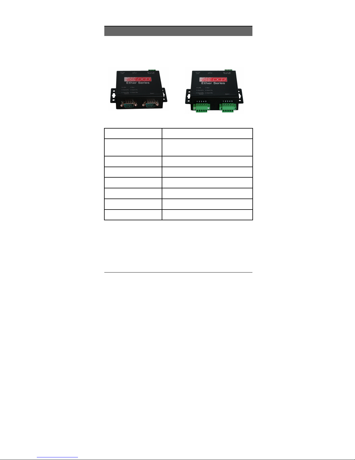
Physical Details
The EDNP-3 front panel is shown below.
EtherSeries EDNP-3 without and with Opto-isolation
Power port
1
10/100Base-T
2
port
RUN LED
3
LAN LED
4
COM1 Tx
5
COM1 Rx
6
COM2 Tx
7
COM2 Rx
8
Connect the power adapter here.
Connect LAN cabling here.
RUN Indicator
LAN Indicator.
Serial Port Transmit Indicator
Serial Port Receive Indicator
Serial Port Transmit Indicator
Serial Port Receive Indicator
3
Page 14

EtherSeries DNP- 3 Gateway User’s Guide
Configuration Switch
There is a momentary action push button switch on the reart of
the unit behind a small hole. Pressing this switch places the
unit in configuration mode and is used only when configuring
the unit via the serial port, as explained in Chapter 3 Configuration. Return from configuration mode by exiting the
configuration menu or by power cycling the unit. This switch
may be depressed with a tiny screw driver or stiff wire. (A
straightened paper clip works nicely).
LED Indicators
There are six red LED indicators on the top panel.
LED Indicators
• The LAN LED is the Ethernet Status indicator. It is lit
when there is a valid 10/100BaseT Ethernet connection.
• This LED flickers off and on with activity on the Ethernet
(even if the activity isn't directly to this unit).
• The RUN LED flickers off and on with ethernet transmit
activity from the EDNP-3.
• The COM port Tx and Rx LEDs flicker off and on with
characters being transmitted or received through the
appropriate serial port.
4
Page 15

Introduction
Package Contents
You should find the following items packaged with your
EtherSeries product:
• The EtherSeries Unit
• Power Adapter (or power supply)
• This User’s Guide
If any of the above are missing, contact your dealer
immediately.
Software Requirements
The EDNP-3 supports DNP-3 (either TCP or UDP) on the
Ethernet interface and DNP-3 serial protocol on the serial ports.
It may be configured using any terminal or terminal emulation
software on a PC via serial port one. Any standard telnet
program may be used to telnet to the unit for configuration, or
any standard web browser may be used for configuration once
the unit has a valid IP address configured. Since any terminal
program (including Microsoft Hyperterm) or web browser may
be used when configuring the unit, there is no supplied
configuration software.
5
Page 16

EtherSeries DNP- 3 Gateway User’s Guide
6
Page 17

Chapter 2
Installation
This Chapter details the LAN installation
process for the EtherSeries product.
Overview
The EtherSeries products may be configured via a serial port,
telnet, or web browser. Initially, the configuration of an IP
address must be performed using the serial port unless the
default IP address of 192.168.1.1 is appropriate for your
Ethernet network.
To use LAN based configuration, either Telnet or Web Browser
based, an IP address must be configured. The default value of
192.168.1.1 may not work with your network.
Terminal Mode configuration may be performed at any time,
and no IP address is required. See Chapter 3 for details.
Quick Start
Quick start instructions are on the next page. Installation is an
easy process that is basically… plug it in, configure IP,
configure DNP-3, and configure the serial ports.
7
Page 18

EtherSeries DNP- 3 Gateway User’s Guide
Installation
1. Connect the Network Cable
The EtherSeries network interface is auto-sensing. Simply
connect your network cable to the appropriate connector on
the rear panel. If you wish to configure ethenet options,
that may be performed later.
2. Connect the Power Adapter Cable
Plug in the power adapter cable. After about a 4 second boot
process the unit is ready for operation. Some configurations
require wiring to a screw-terminal block.
3. Configure IP Address Information
Using the default address and telnet or a web browser OR using
a serial port and terminal emulation, configure the IP and DNP3 ethernet information. At a minimum, the IP address and port
number must be configured.
4. Configure a Serial Port
Configure the appropriate serial ports for the proper DNP-3
protocol, slave address range, and timeouts.
5. Configure the DNP-3 Host.
You are now ready to use the EtherSeries Gateway. Configure
the DNP-3 host computer and the serial RTUs for proper
operation and start using it!
8
Page 19

Configuration
Chapter 3
Terminal/Telnet
Configuration
This Chapter describes how to manage the
EtherSeries product using Terminal, or Telnet
mode. Web Browser mode management is
detailed in Chapter 4.
Overview
The EtherSeries unit may be managed using any of the
following methods:
• Web Browser - After installing the unit in your LAN, use
your Web Browser for management. See Chapter 4 -
Browser Configuration for details.
• Terminal Mode - Use a serial cable connection and a
communication program. This is often required prior to
other modes in order to configure a compatible IP address
into the unit.
• Telnet Mode - After installing the unit in your LAN,
manage it using Telnet.
Both Terminal and Telnet modes provide the same user
interface.
9
Page 20

EtherSeries DNP- 3 Gateway User’s Guide
Terminal Configuration
Terminal configuration requires the following:
• PC with terminal emulation program, or a dumb terminal.
• Serial cable to connect the PC to the unit. See the
Appendix for cable requirements. A Crossover (null
modem) cable is required when using a 9-pin PC port.
• Serial port 1 must be configured as an RS-232 port. This is
the factory default configuration.
Procedure
1. Connect the unit to your PC or terminal.
2. Connect the unit to the power supply.
3. Press the configuration setup switch momentarily. It is
located to the side of the power connector and accessed
through a small hole. Use a small pen or paper clip to
access the switch.
4. Configure the terminal program with the following settings.
Setting Value
Flow control protocol None
Speed 9600
Data 8 bits
Parity None
Stop Bit 1
5. Configure your terminal program to the appropriate port
(e.g. COM 1).
10
Page 21

Configuration
6. The configuration program should now start and after a
few seconds display a sign-on screen.
If nothing appears on your screen, press ESC.
Refer to the Terminal/Telnet Interface chapter for details
on using the configuration program.
Telnet Management
NOTE: To use telnet, there MUST be compatible IP
addresses in both the PC and the unit!
1. Install the unit into your LAN as described in Chapter 2.
Ensure that the unit is powered on.
2. Connect to it with the telnet program on your workstation.
A typical command is:
telnet IP_Address 8000
Where:
IP_Address is the IP address of the unit.
8000 is the management port number. For example, if the
default IP address has not been changed, then you would
enter the command:
telnet 192.168.1.1 8000
If you can't connect
If the unit does not respond, check the following:
• It is properly installed, LAN connections are OK, and it
is powered ON.
• Check that your PC is using a compatible IP Address
and Network Mask.
In Windows, using Control Panel-Network to examine
the Properties for the TCP/IP protocol can check the IP
11
Page 22

EtherSeries DNP- 3 Gateway User’s Guide
Address and Network Mask. If your PC is NOT using an
IP Address within the range 192.168.1.2 to
192.168.1.254, with a Network Mask of 255.255.255.0,
then it will not connect to the default IP address.
3. Refer to the following section for details on using
command line management.
12
Page 23

Configuration
Terminal/Telnet Interface
The banner screen displays the version number.
DNP Server Gateway V3.0
------------------------------- Device Name: GW00479E
Physical Location: Head Office
Configuration setup.
[Press any key to continue]
Pressing any key will then take you to the Main Menu.
Main Menu
----------------------------------------- 1 Set Local IP Address,
Subnet Mask, and Gateway Address
2 Set Manager/Telnet IP Address
3 Serial Port 1 Configuration
4 Serial Port 2 Configuration
5 DNP LAN Configuration
6 DNP Serial Configuration
7 Security Configuration
8 SNMP Configuration
9 Display Configuration Settings
R Reset Configuration to Default
S Save and Exit
0 Exit without Saving
Choose a Number =>
Each of these menu options is explained in the following pages.
13
Page 24

EtherSeries DNP- 3 Gateway User’s Guide
Entering Data
Enter the number of the field you wish to change, followed (on
the same line) by a space and the data for that field.
Example
On screen one, to set the IP address (field 1) to 192.168.1.10
=>1 192.168.1.10
Menu Options
Main Menu Option 1.
Setting IP Addresses
Selecting 1 (1 Local IP Address) from the Main Menu will
result in a screen which is similar to the following.
LOCAL UNIT CONFIGURATION:
Local Address: 205.166.54.137 Serial NO:
00:60:E9:00:47:9E
Gateway Address: (NOT SET) Subnet Mask:
255.255.255.0
IP Fragmentation: ALLOWED
Ethernet Mode: Auto
SET LOCAL UNIT CONFIGURATION:
1 Local IP Address
2 Subnet Mask
3 Gateway IP Address
4 IP Fragmentation [0=ALLOWED, 1=NOT ALLOWED]
5 Ethernet Mode [0=Auto, 1=100Mb-Full, 2=100MbHalf, 3=10Mb-Full, 4=10MB-Half]
0 -- Return to previous menu
EXAMPLE: To set local IP address to 192.168.0.100
=> 1 192.168.0.100
Enter Command =>
14
Page 25

Configuration
1. Local IP Address
The IP address of this unit on your LAN. The default IP
Address is 192.168.1.1
2. Subnet Mask
The network mask indicates what class of TCP/IP network you
have. The default value is for a class “C” network, with up to
255 users. This value should work in small networks. If in
doubt, consult your network administrator .
3. Gateway IP Address
If the remote host is not on the same LAN, then the gateway to
the other LAN must be entered here.
4.IP Fragmentation
The unit may be instructed to not fragment any outgoing
ethernet packets. If this is turned on, then the DoNotFragment
bit is also set in all IP packets. Note that all routers do not
abide by this directive, and the packets may be fragmented in
transit.
5. Ethernet Mode
The ethernet interface may be forced in either Half or Full
Duplex, and 10Mbps or 100Mbps speeds, or these values autonegotiated with the connected switch/hub. Normally set for
AUTO, this field allows the unit to force one of the modes for
compatibility with ethernet switches that negotiate incorrectly.
15
Page 26

EtherSeries DNP- 3 Gateway User’s Guide
Main Menu Option 2.
Set Manager/Telnet IP Address
Selecting (2) from the Main Menu will result in the following
screen. Caution! If these addresses are set, only those nodes
will be allowed to configure the unit.
MANAGER CONFIGURATION:
Entry Manager_IP_Addr
***** ***************
1. 0.0.0.0
2. 0.0.0.0
3. 0.0.0.0
4. 0.0.0.0
SET MANAGER CONFIGURATION:
set Entry_Number IP_Address
clear Entry_Number
0 --Return to main menu.
EXAMPLE: To set entry #3 to IP address=138.239.0.24,
=> set 3 138.239.0.24
EXAMPLE: To clear entry #2 IP address,
=> clear 2
Enter Command =>
This screen shows a table containing four (4) entries. By
default, all entries are blank. These entries provide a security
feature. Only a user at one of the IP addresses shown can
manage the unit. (All users on the LAN can still use the
gateway, but not configure it.)
If the entries are blank, then any user on the LAN can
configure the gateway.
Entries in the table cannot be edited, but commands are
provided to insert (SET) and delete (CLEAR) entries.
16
Page 27

Configuration
Main Menu Options 3 & 4.
Serial Port Configuration
Selecting (3) from the Main Menu will result in the following
screen for port 1. Selecting (4) from the Main Menu will result
in a similar screen for port 2.
PORT 1 CONFIGURATION:
Baud Rate: 9600
RS485: 4-wire [RS232 selected]
TX Delay after RTS Active: 0 ms
SET PORT CONFIGURATION:
1 Baud Rate [0=230400, 1=115200, 2=57600, 3=38400,
4=19200,
5=9600, 6=4800, 7=2400, 8=1200,
9=600, 10=300]
2 RS485 Mode [0=4-wire, 1=2-wire]
3 TX Delay after RTS Active [0 - 5000 ms]
0 -- Return to previous menu.
EXAMPLE: To set the baud rate to 9600
=> 1 5
Enter Command =>
This screen configures the settings for the serial ports. The
settings used should match the device connected to the serial
ports of the gateway.
Baud Rate
Speeds between 300 bps and 230.4Kbps are supported.
RS-232/422/485 Mode
Configure the port for either RS-422/485 4-wire, RS-485 2wire, or RS-232.
17
Page 28

EtherSeries DNP- 3 Gateway User’s Guide
Tx Delay after RTS Active
This parameter sets the minimum amount of time to delay after
asserting RTS before sending data. Set to a value between 1
and 5000 msec (5 seconds).
18
Page 29

Configuration
Main Menu Option 5.
DNP LAN Configuration
Selecting (5) from the Main Menu will result in the following
screen:
DNP LAN CONFIGURATION:
LAN Protocol: TCP
TCP/UDP Port: 19968
TCP Connection Timeout: 120 seconds
SET DNP LAN CONFIGURATION:
1 LAN Protocol [0=TCP, 1=UDP]
2 TCP/UDP Port [0 - 65535]
3 TCP Connection Timeout [10 - 3600 seconds]
0 -- Return to previous menu
EXAMPLE: To set the Connection Timeout to 120 seconds
=> 3 120
Enter Command =>
Use this screen to configure DNP-3 TCP/UDP configuration
values.
LAN Protocol
Set to either TCP or UDP. This must match the protocol used
by your polling host computer.
TCP/UDP Port
This is the TCP/IP port number used by the gateway. Default is
normally set to port 20000.
TCP Connection Timeout
This parameter sets the amount of time the Gateway will hold
an idle TCP connection open before closing it. Default is 120
seconds.
19
Page 30

EtherSeries DNP- 3 Gateway User’s Guide
Main Menu Option 6.
DNP Serial Configuration
Selecting (6) from the Main Menu will
result in the following screen:
DNP SERIAL CONFIGURATION:
Port 1 DNP Address Low: 256 (0100 hex)
Port 1 DNP Address High: 65527 (FFF7 hex)
Port 2 DNP Address Low: 256 (0100 hex)
Port 2 DNP Address High: 65527 (FFF7 hex)
SET DNP SERIAL CONFIGURATION:
1 Port 1 DNP Address Low [0 - 65534]
2 Port 1 DNP Address High [0 - 65534]
3 Port 2 DNP Address Low [0 - 65534]
4 Port 2 DNP Address High [0 - 65534]
0 -- Return to previous menu
EXAMPLE: To set the Port 1 low address limit to 200
=> 1 200
Enter Command =>
Use this screen to configure DNP serial configuration values.
For each of the ports (1 or 2) configure the following…
RTU DNP Address Low
Configures the lowest address of an RTU on this port.
RTU DNP Address High
Configures the highest address range of an RTU on this port. If
the ranges of port one and port two overlap, addresses in the
overlap will be sent to port one.
.
20
Page 31

Configuration
Main Menu Option 7.
Security Configuration
Selecting (7) from the Main Menu will
result in the following screen:
SECURITY CONFIGURATION:
Web Configuration: ENABLED
Telnet Configuration: ENABLED
SNMP Agent: ENABLED
Index UserName Password
----- -------- ------- 1:
2:
3:
SET SECURITY CONFIGURATION:
1 Disable Web Configuration [0=ENABLED, 1=DISABLED]
2 Disable Telnet Configuration [0=ENABLED,
1=DISABLED]
3 Disable SNMP Agent [0=ENABLED, 1=DISABLED]
4 Set User ID and Password [index userid password]
5 Clear User ID and Password
0 -- Return to previous menu
EXAMPLE: To set User ID 1 to root, password toor
=> 4 1 root toor
Enter Command =>
This product uses industry standard IP protocols. Since IP is a
well-known standard, its security vulnerabilities are also well
known and may be exploited. Several options are available to
enhance the inherent security of your network. However, since
network security is a moving target and absolute security is
never achievable, every network installation should be designed
and implemented with care to minimize security risks in a way
that is appropriate for the application and perceived risks.
21
Page 32

EtherSeries DNP- 3 Gateway User’s Guide
A full description of the configuration security options is
presented in Chapter 7 and should be fully understood before
implementation on an insecure network.
In this section, the following options are configured:
Web Configuration
The ability to configure the gateway using a web browser may
be enabled or disabled.
Telnet Configuration
The ability to configure the gateway using a telnet client may
be enabled or disabled.
SNMP Client functionality
The ability to communicate with the gateway using a SNMP
may be enabled or disabled.
Set User ID and Password
Configure the configuration user name and password, if
enabled.
Clear User ID and Password
Clear (turn off) the configuration user name and password, if
enabled.
22
Page 33

Configuration
Main Menu Option 8.
SNMP Configuration
Selecting (8) from the Main Menu will
result in the following screen:
SNMP CONFIGURATION:
Name of Contact Person: Supervisor
Device Name: GW00479E
Physical Location: Head Office
SNMP Community: public
SET SNMP CONFIGURATION:
1 Name of Contact Person
2 Device Name
3 Physical Location
4 SNMP Community
0 -- Return to previous menu
Enter Command =>
This information may be ignored if SNMP is not used.
These are text fields, commonly used in SNMP (Simple
Network Management Protocol) Programs to identify this
device when browsing or managing the network.
These values have no effect on the functional operation of the
unit. Other standard MIB values are returned to the SNMP
manager along with this information. The gateway may not be
remotely configured using SNMP.
The MIB file is available from the DCB website.
23
Page 34

EtherSeries DNP- 3 Gateway User’s Guide
Main Menu Option 9.
Display Configuration Settings
Selecting (9) from the Main Menu will display the following
information:
DNP Server Gateway: V1.0
LOCAL UNIT CONFIGURATION:
Local Address: 205.166.54.137 Serial NO:
00:60:E9:00:47:9E
Gateway Address: (NOT SET) Subnet Mask:
255.255.255.0
IP Fragmentation: ALLOWED
Ethernet Mode: Auto
SNMP CONFIGURATION:
Name of Contact Person: Supervisor
Device Name: GW00479E
Physical Location: Head Office
SNMP Community: public
MANAGER CONFIGURATION:
Entry Manager_IP_Addr
***** ***************
1. 0.0.0.0
2. 0.0.0.0
3. 0.0.0.0
4. 0.0.0.0
[Press any key to continue]
24
Page 35

PORT 1 CONFIGURATION:
Baud Rate: 9600
RS485: 4-wire [RS232 selected]
TX Delay after RTS Active: 0 ms
PORT 2 CONFIGURATION:
Baud Rate: 9600
RS485: 4-wire
TX Delay after RTS Active: 0 ms
[Press any key to continue]
DNP LAN CONFIGURATION:
LAN Protocol: TCP
TCP/UDP Port: 19968
TCP Connection Timeout: 120 seconds
DNP SERIAL CONFIGURATION:
Port 1 DNP Address Low: 256 (0100 hex)
Port 1 DNP Address High: 65527 (FFF7 hex)
Port 2 DNP Address Low: 256 (0100 hex)
Port 2 DNP Address High: 65527 (FFF7 hex)
CURRENT STATISITCS:
LAN packets sent: 343
LAN packets rcvd: 13598
LAN packet errors: 0
DNP no path errors: 0
DNP no path errors: 0
DNP broadcasts: 0
Configuration
SERIAL PORT: 1 2
------- ------ Port bytes sent: 0 0
Port bytes rcvd: 0 0
Port packets sent: 0 0
25
Page 36

EtherSeries DNP- 3 Gateway User’s Guide
Port packets rcvd: 0 0
Port Receive errors: 0 0
Dest addr errors: 0 0
Source addr errors: 0 0
TCP Host List
[Press any key to continue]
This option displays the configuration and some operational
counters. A list of TCP hosts recently contacted is also
included.
Main Menu Option R.
Reset Configuration to Default
Selecting (R) from the Main Menu will restore all values to
their default values.
If using Telnet or web browser configuration, the connection
will be lost when the hardware reboots. To reconnect, you must
use the default IP Address of 192.168.1.1 or change the IP
address before rebooting with main menu option 6. The
preferred method is to restore defaults with menu item 8, and
then BEFORE REBOOTING, change the IP information by
using submenu 1 so your PC will still be able to connect to the
gateway when it reboots.
26
Page 37

Configuration
Main Menu Option S.
Save and Exit
Selecting (S) from the Main Menu will store the configuration
details in the gateway and exit the configuration program.
If using Telnet, the connection will be lost when rebooting. If
you have changed the IP Address, you must use the new IP
Address when you reconnect.
Main Menu Option 0.
Exit without Saving
Selecting (0) from the Main Menu will exit the configuration
program without saving any data you have entered.
27
Page 38

EtherSeries DNP- 3 Gateway User’s Guide
28
Page 39

Chapter 4
Browser
Management
This Chapter describes how to manage the
EtherSeries Gateway using a Web Browser.
Overview
This method uses your Web Browser to manage the gateway.
This provides a more user-friendly interface than the
Telnet/Terminal method.
• The unit must be installed in your LAN and have a
compatible IP address before this configuration method
can be used.
• Most Browsers will work. The only requirement is that
they support HTML tables and forms. If your browser uses
a proxy, the proxy function may need to be disabled.
Connection Procedure
To establish a connection to the gateway , follow this
procedure:
1. Install the unit in your LAN as described in Chapter 2.
Ensure that it is powered on and there is a link light on the
hub or ethernet switch.
29
Page 40

Etherseries DN P- 3 Gateway User’s Guide
2. Start your Web browser.
3. In the Address box of your browser, enter the following:
http://IP_Address
(IP_Address is the IP address of the gateway)
For example, if the default IP address has not been
changed, then you would enter the command:
http://192.168.1.1
If you can't connect
If it does not respond, check the following:
• The gateway is properly installed, LAN connections are
OK, and it is powered ON.
• Check that your PC is using a compatible IP Address
and Network Mask.
In Windows98, using Control Panel-Network to
examine the Properties for the TCP/IP protocol can
check the IP Address and Network Mask.
If your PC is NOT using an IP Address within the range
192.168.1.2 to 192.168.1.254, with a Network Mask of
255.255.255.0, it will not be able to communicate with
the gateway.
4. Once connected, you will see the first screen. Refer to the
following section for details on using the Web-based
interface.
30
Page 41

Configuration
Web-based Interface
The first screen is similar to Figure 2.
Figure 1: Sign on Screen
• Use the menu bar on the left to navigate to the desired
screen.
• On-line help is available on each screen.
• Each screen is explained in the following sections.
• Details for each field are given in the previous chapter
under similar sections.
31
Page 42

Etherseries DN P- 3 Gateway User’s Guide
Serial Port Configuration Screen
Figure 2: Serial Configuration Screen
This screen allows you to configure the Serial Ports one and
two. The settings used should match the device connected to
this serial port. See Chapter 3 for details on these settings.
There will be one screen for each serial port.
32
Page 43

Configuration
DNP-3 Configuration Screen
Figure 3:DNP Configuration
This screen is used to configure all DNP parameters.
33
Page 44

Etherseries DN P- 3 Gateway User’s Guide
LAN Configuration Screen
Figure 4: LAN Configuration Screen
This screen is used to configure the LAN parameters. See
Chapter 3 for details.
34
Page 45

Configuration
SNMP Configuration Screen
Figure 5: SNMP Configuration Screen
Overview
This screen may be ignored if SNMP is not used.
The text fields, commonly used in SNMP (Simple Network
Management Protocol) Programs to identify this device when
browsing the network, are required for SNMP operation. The
community name should be changed from the default.
35
Page 46

Etherseries DN P- 3 Gateway User’s Guide
Configuration Summary Screen
Figure 6: Configuration Summary Screen
(Top portion shown)
Operation
• This screen displays all current settings for this
gateway.
• Clicking the "Set to Defaults" button will restore ALL
values to their factory default values.
When this is done, the unit will reboot, and the
existing connection will be lost. You must reconnect
using the default IP Address of 192.168.1.1.
36
Page 47

Configuration
Port Activity Screen
Figure 7: Port Activity Screen
Operation
• This screen displays all current activity for the LAN
port and both serial ports.
• Values are described in Chapter 3.
37
Page 48

Etherseries DN P- 3 Gateway User’s Guide
38
Page 49

Configuration
Chapter 5
Operation
This Chapter explains how to use the
EtherSeries gateway, once it is installed and
configured.
Operation
The gateway allows serial DNP-3 RTUs to communicate and
interoperate with DNP-3 UDP/TCP based controllers. The
DNP-3 standard protocol is an asynchronous protocol designed
to connect directly to computer asynchronous ports. DNP-3
has been extended to operate over Ethernet using the IP
protocol suite. This gateway converts between the DNP-3
UDP/IP or TCP/IP protocol and DNP-3 serial protocols
transparently.
Normal operation would consist of one or more Ethernet based
computers functioning as DNP03 Master and one or more
DNP03 remote devices (usually RTUs) connected serially to
the gateway.
By using RS-485, multiple DNP-3 slave devices may be
connected to each of the two serial ports on the gateway. If
using RS-232, one DNP03 slave device may be connected
to each serial port.
39
Page 50

Chapter 6
Configuration
Security
This section discusses configuration options
that restrict configuration.
Overview
The gateway uses the industry standard IP protocols. Since IP
is a well-known standard, its security vulnerabilities are also
well known and may be exploited. Several gateway options are
available to enhance the inherent security of your network.
However, since network security is a moving target and
absolute security is never achievable, every network installation
should be designed and implemented with care to minimize
security risks in a way that is appropriate for the application
and perceived risks.
The gateway may be configured with several levels of security
configuration and authentication. These restrict the ability of
an unwanted user from changing the configuration of the
gateway. They do not restrict the ability of a remote device to
deliver packets to the gateway’s data port.
At the level 0, any workstation may be used to configure the
gateway via either telnet or web browser configuration. Level 1
40
Page 51

Security
restricts configuration to workstations claiming to be from one
of four IP addresses previously stored in the gateway. Either
web-based or telnet configuration is allowed. Level 2 disables
remote configuration using web browser, telnet, or SNMP in
any combination. Level 3 requires a user name and password
for remote configuration. Combinations of Level 2 and Level 3
are possible (ie. One may disable web browser configuration
and SNMP and require a username/password for telnet
configuration. The most secure method would be to disable all
remote configuration.
The gatewayl may always be configured using the direct
connected terminal method. This requires physical access to
the hardware, and pressing the configuration button while a
terminal (or PC) is connected to the serial port.
Level 0:
No specific security configuration is required. Make sure that
no IP addresses have been entered in menu item 2, "Set
Manager/Telnet IP Address" screen (or the "Administrator
Access Rights of the web browser "Configure LAN" screen).
Also, any user name/password pairs that may have been entered
on the terminal configuration/telnet "Security Configuration"
screen should be cleared.
41
Page 52

Etherseries DN P- 3 Gateway User’s Guide
Level 1:
Using any configuration method, configure Administrator
Access IP addresses. Enter the IP addresses that should have
the ability to change the gateway configuration. If configuring
this remotely, insure that the workstation you are using is one of
the valid addresses.
Level 2:
Using telnet or direct connection configuration, selectively
enable or disable remote configuration via Telnet, via web
browser, and SNMP. This setting may not be performed from
the web configuration screen.
Level 3:
Configure Level 1 and Level 2 security as needed. Using the
telnet or direct connection configuration, enter up to three user
name and password pairs. If there is at least one user name in
this list, then a password prompt will be issued upon
establishing a telnet configuration session.
There may be up to 3 user names and passwords configured. If
no users are configured, password protection is disabled. User
names and passwords are limited to 8 characters each. There is
a six failed login attempt limit. After six failed attempts in a
row, the unit will lock out all logins for a period of about 10
minutes.
Each user name has an associated user ID or index. The user
with ID 1 is considered the master user. It has the ability to
42
Page 53

Security
change the other user names and passwords. The other two
user ID's are limited to only changing their own user name and
password. All users may modify any other system parameters.
The serial interface is not subjected to user login since it
requires physical access to the unit.
SECURITY CONFIGURATION:
Web Configuration: ENABLED
Telnet Configuration: ENABLED
SNMP Agent: ENABLED
Index UserName Password
----- -------- --------
1:
2:
3:
SET SECURITY CONFIGURATION:
1 Disable Web Configuration [0=ENABLED, 1=DISABLED]
2 Disable Telnet Configuration [0=ENABLED, 1=DISABLED]
3 Disable SNMP Agent [0=ENABLED, 1=DISABLED]
4 Set User ID and Password [index userid password]
5 Clear User ID and Password
0 -- Return to previous menu
EXAMPLE: To set User ID 1 to root, password toor
=> 4 1 root toor
Enter Command =>
Security Configuration Screen
43
Page 54

44
Page 55

Troubleshooting
Chapter 7
Troubleshooting
This chapter outlines some problems that may
occur during installation or operation and
some possible solutions to them.
If you follow the suggested troubleshooting steps and the
EtherSeries gateway still does not function properly, please
contact your dealer for further advice.
Hardware Problems
Before anything else, check that all cables are wired
correctly and properly connected.
P: All the LEDs are off.
S: Check the power supply or power connection.
P: When using 10/100Base-T cabling, the unit does not work.
S: Check the Hub’s link LED for the port to which the gateway
is connected. If it is off, make sure the network cable
between the unit and hub is in good condition.
45
Page 56

Etherseries DN P- 3 Gateway User’s Guide
Can't Connect via the LAN
P: Can't connect to the gateway using Telnet or Web Browser.
S: Check the following:
• Start troubleshooting from a known state. Power the
unit OFF and ON to reboot.
• Is a proper IP address configured?
• “Ping” the unit to see if it responds. From the
Windows command prompt or “Run” dialog box, use
the command:
ping IP_Address
Where IP_Address is the IP Address of the
gateway (e.g. ping 192.168.1.1 ). If it does not
respond, then check all LAN connections. If the LAN
connection are OK, the problem is in the LAN
addresses or routing. The most common problem
cause is incorrect IP addressing. Make sure the
workstation and gateway have compatible IP
addresses.
• It may be that your "arp table" contains invalid entries.
You can clear the "arp table" by rebooting, or, on
Windows95 , by typing the following command at the
command prompt or Run dialog box.: arp -d
• Check that you have used the correct port address for
telnet access. The address is “8000” for configuration.
• MOST connection problems are due to incorrect RS-
232 wiring. Remember that there is no "standard" RS232 wiring between devices. You may need to contact
your vendor for appropriately wired cables.
46
Page 57

Troubleshooting
• In some cases, “smart” hubs and switches must be
power-cycled to clear their internal arp cache. This is
often a problem on test bench setups where IP
addresses are moved between different equipment or a
unit is moved between ethernet switch receptacles.
47
Page 58

Etherseries DN P- 3 Gateway User’s Guide
Other Problems
P: Can’t run the configuration program using a serial cable
connection.
S: Check that:
• The communication parameters are set properly.
• Disconnect and reconnect the power supply.
• Power is available... a LED is on.
• The terminal program is operating properly. Try a
loopback connector at the gateway end of the cable to
verify program operation and the proper COM: port.
• The most common problems causing this symptom
are incorrect RS-232 wiring or the Windows
Hyperterm program not operating correctly.
P: Unable to poll some addresses.
S: Read the section on DNP-3 configuration. If port one and
port two addresses overlap, the overlaped addresses are
only sent out port one.
P: Unable to poll ANY addresses.
S: Read the section on DNP-3 configuration. Insure that the
host computer and gateway are using the same IP protocol
(TCP vs. UDP).
48
Page 59

Troubleshooting
Verify Proper Operation
Once the gateway is installed on your Network, verify
proper operation by testing its functionality. SCADA
networks vary greatly, so there is no simple way to
describe testing all possibilities. Use a scientific method
and keep careful records of all installation and
troubleshooting steps. For example, consider the following
method…
1. Verify that the gateway has a proper LAN connection by
pinging it. If it responds to a ping then…
2. Verify the unit’s configuration by using telnet to port 8000
or by checking it using a web browser. If it looks good
then…
3. Attempt a poll from the DNP-3 polling master computer.
If that works correctly, you’re ready to continue with
DNP03 operation. IF not…
4. Check the gateway’s statistics to see if it received the LAN
activity and passed the polls to a serial port. If not, there is
likely a problem with IP addressing or the host computer is
not configured correctly for the gateway’s LAN. If the
gateway receives the LAN packets and doesn’t pass them
to the serial port, then check its configuration. If the
counters indicate that the poll was passed to the serial port,
but there’s no response…
5. Verify correct RS-232/RS-485 configuration. Verify
cabling to the RTU. One of these is likely incorrect. Or…
6. Verify the RTU configuration. Perhaps it’s not correctly
configured.
49
Page 60

Etherseries DN P- 3 Gateway User’s Guide
50
Page 61

Appendix A
Specifications
EtherSeries Gateway Specifications
• Flash Memory: 512 Kbytes
• SRAM: 512 Kbytes
• EEPROM: 512 Bytes
• LAN Buffer: 2 Kbytes
• RS-232 Buffer: 4 Kbytes
• RS-232/485: two male DE-9 connectors (PC DB-9)
• RS-485 Isolated: two screw terminals
• RS-232 speed: Up to 230 Kbps
• Network: Ethernet 10Base-T/ 100Base-T
• CPU: 16 Bit
• Power: 9 to 30 VDC (12VDC @ 260 ma) or Optional
power supplies
• Switch: Configuration Mode
• LED indicators: 6 on top panel
• Default IP address: 192.168.1.1
• Telnet management port: 8000
• Operational Temperature -40C to +70C
51
Page 62

Etherseries DN P- 3 Gateway User’s Guide
RS-232 PIN Assignments
The EtherSeries RS-232 port wiring is identical to a standard
PC 9 pin DE-9P COM: port. It operates as a DTE device. The
chart below details signal directions and names.
Serial Port Pin Assignments
Pin Signal Name Type
1 Carrier Detect (CD) In
2 Receive (Rx) In
3 Transmit (Tx) Out
4 Data Terminal Ready Out
5 Signal Ground (GND) Power
52
6
Data Set Ready (DSR)
7 Request to Send (RTS) Out
8 Clear to Send (CTS) In
9 Ring Indicator (RI) (Not used) In
In
Page 63

Specifications
Control Signal Operation
DCD
Input, ignored
Receive Data
Input, data into the unit
Transmit Data
Output, Data from the unit. The Etherseries unit only transmits
when it has characters to send, and if handshaking is enabled,
when the CTS input is asserted.
DTR
Output. Signal is asserted when the unit is powered on.
Signal Ground
Common ground
DSR
Input, ignored.
RTS
Output. If handshaking is disabled, this signal is always
asserted. If handshaking is enabled, it will be asserted when the
gateway has a packet to transmit on the serial port and it will be
de-asserted when transmission is complete.
CTS
Input. When handshaking is disabled, this signal is ignored.
When handshaking is enabled, the gateway will wait for CTS to
be asserted before transmitting a packet on the serial port.
53
Page 64

Etherseries DN P- 3 Gateway User’s Guide
Ring Indicator
Not used
54
Page 65

Specifications
S S -1
1,6
2
3
4
5
7
8
P C
4
3
2
1,6
5
8
7
CABLES
Commonly used cable connections:
To PC 9-pin COM: port
This null-modem crossover cable is easily made by combining
two “PC-Direct” adapter hoods with a mux-mux crossover
cable from DCB. This cable is used for configuration and is
available from your dealer. This is commonly called a "PC-toPC null modem cable".
Gateway to RTU
Since RTUs vary in pinout configuration, no standard cable
may be specified. Since the gateway pinout is similar to a PC
COM: port when configured in RS-232 mode, a PC-to-RTU
cable may be used that is the same cable that works between
YOUR PC and YOUR RTU.
Note that if the RTU has a pinout similar to a PC, then a crossover (null-modem) cable must be used.
55
Page 66

Etherseries DN P- 3 Gateway User’s Guide
56
Page 67

Specifications
Appendix B
RS-422/ RS-485
Interface
This Appendix describes the RS-422/485
interface. This interface option may be
selected during configuration in the field.
Introduction
The 9-pin serial connector may be used for either RS-232, RS422 (4-wire RS-485 point-to-point), or 2-wire RS-485
operation by changing software configuration settings on the
Configure Port screens..
57
Page 68

Etherseries DN P- 3 Gateway User’s Guide
RS-422 / 4-Wire RS-485 Interface
Pinout
Serial Port Pin Assignments
Pin Signal Name Type
1 No Connection N/A
2 Transmit Data (TX+) Out
3 Receive Data (Rx+) In
4 No Connection N/A
5 Signal Ground (GND) N/A
6 No Connection N/A
7 Receive Data (Rx-) In
8 Transmit Data (Tx-) Out
9 No Connection N/A
58
Page 69

Specifications
2-Wire RS-485 Interface Pinout
Serial Port Pin Assignments
Pin Signal Name Type
1 No Connection N/A
2 No Connection N/A
3 Data + In/Out
4 No Connection N/A
5 Signal Ground (GND) N/A
6 No Connection N/A
7 Data - In/Out
8 No Connection N/A
9 No Connection N/A
RS-485 2-wire Fan-out
Since this unit is most often used as an RS-485 2-wire endpoint, it will support 32 devices on the RS-485 line. Use
good engineer practice for RS-485 lines. Where applicable,
include termination for long lines.
59
Page 70

Etherseries DN P- 3 Gateway User’s Guide
RS-422 / 4-Wire RS-485 Interface
Pinout With Optical Isolation
There is a RS-485/422 only model with optical isolation. This
unit does not include RS-232 ports. The Optical Isolated
version uses screw terminal connectors.
Serial Port Pin Assignments
Pin Signal Name Type
1 Transmit Data (TX+) Out
2 Transmit Data (Tx-) Out
3 Receive Data (Rx+) In
4 Receive Data (Rx-) In
5 Signal Ground (GND) N/A
60
 Loading...