

Page 1

EtherPoll
User’s Guide
Revised October 7, 2002
Firmware Version 4.1
Page 2

Page 3

FCC Statement
This device complies with the limits for a Class B digital
device, pursuant to Part 15 of the FCC rules. Operation is
subject to the following two conditions:
(1) This device may not cause harmful interference.
(2) This device must accept any interference received,
including interference that may cause undesired
operation.
CE Marking Warning
This is a class B product. In a domestic environment this
product may cause radio interference in which case the user
may be required to take adequate measures.
Copyright 200, 2002. All rights reserved.
Version 4.0
All trademarks and trade names are the properties of their
respective owners.
Page 4

Page 5

ABLE OF CONTENTS
T
Chapter 1 Introduction ............................................ 1
EtherPoll Functions......................................................3
Other Features..............................................................5
Physical Details............................................................6
Configuration Switch.............................................7
LED Indicators......................................................8
Package Contents ................................................10
Software Requirements .......................................10
Chapter 2 Installation ............................................11
Overview....................................................................11
LAN Installation ........................................................11
Chapter 3 Terminal/Telnet Configuration........... 13
Overview....................................................................13
Terminal Configuration..............................................14
Procedure ............................................................14
Telnet Configuration..................................................15
Terminal/Telnet Interface ..........................................17
Entering Data ......................................................18
Menu Options......................................................18
Chapter 4 Browser Configuration ........................32
Overview....................................................................32
Connection Procedure................................................32
i
Page 6

Web-based Interface.................................................. 34
Port Configuration Screen .................................. 35
Port Activity Screen............................................ 36
Advanced Configuration Screen ......................... 38
LAN Configuration Screen ................................. 41
SNMP Configuration Screen .............................. 44
Configuration Summary Screen.......................... 46
Chapter 5 Configuration Security........................49
Overview ................................................................... 49
Level 0:...................................................................... 50
Level 1:...................................................................... 51
Level 2:...................................................................... 51
Level 3:...................................................................... 51
Chapter 6 Operation...............................................53
Normal Mode ........................................................... 53
Broadcast Mode ........................................................ 54
Point-to-Point Mode.................................................. 54
Chapter 7 Troubleshooting ....................................55
Hardware Problems................................................... 55
Can't Connect via the LAN........................................ 56
Other Problems.......................................................... 58
Checking Device Operation.......................................60
Appendix A Specifications .....................................61
EtherPoll Specifications ............................................ 61
RS-232 PIN Assignments.......................................... 62
ii
Page 7

Introduction
Control Signal Operation ...........................................63
CABLES ....................................................................65
Appendix B Advanced Operation Information ...67
Introduction................................................................67
Description and Behavior...........................................68
Ports used by the EtherPoll .................................68
Normal Operation Modes....................................68
Point - to - Point Mode........................................69
Broadcast Mode ..................................................69
Transmit Conditions............................................69
Application Notes ......................................................70
Protocols .............................................................70
Quick Set-Up.......................................................70
Appendix C RS-422/ RS-485 Interface ................. 71
Introduction................................................................71
Changing the Setting ...........................................71
RS-422 / 4-Wire RS-485 Interface Pinout .................72
iii
Page 8

Page 9

Chapter 1
Introduction
This chapter provides an overview of the
EtherPoll's features and capabilities.
ongratulations on the purchase of your new EtherPoll. The
C
EtherPoll is a SCADA communications serial server that allows
multi-drop devices to use Ethernet LAN's. The EtherPoll
connects any async serial device through a LAN and between
LAN's via routers. The EtherPoll is designed specifically to
support asynchronous polling protocols, such as Poll Select,
Modbus, DNP, etc. These protocols are often error corrected,
and the EtherPoll allows these protocols to work through routed
LANs and over IP protocol networks. The EtherPoll uses the
UDP/IP protocol, allowing the necessary data connection over
a local LAN and across routed networks.
The EtherPoll functions independently of the device protocol,
allowing most 8 bit asynchronous protocols to be used with no
configuration changes.
The EtherPoll can receive data from any Serial device, convert
the data to a valid IP packet, and transmit that data over the
LAN/WAN. Serial devices can then be accessed from anywhere
on your LAN/WAN by any workstation computer using another
EtherPoll. Two EtherPolls may be used in “nailed-up” mode
to build a “RS-232 path” through the WAN/LAN.
Most EtherPolls are used with multi-drop SCADA RTUs;
although a pair of EtherPolls configured for point-to-point
1
Page 10

Etherpoll User’s Guide
operation may be used by any async serial devices such as
alarms, access control devices, and Multiplexers.
For easy connection to your LAN, the EtherPoll supports
10BaseT or 100BaseT with autosensing.
NOTE: A similar product, the EtherPath, uses TCP/IP protocol
and may be more appropriate for some installations. If the
application is not a polled environment, the EtherPath should
be investigated.
2
Page 11
Introduction
EtherPoll Functions
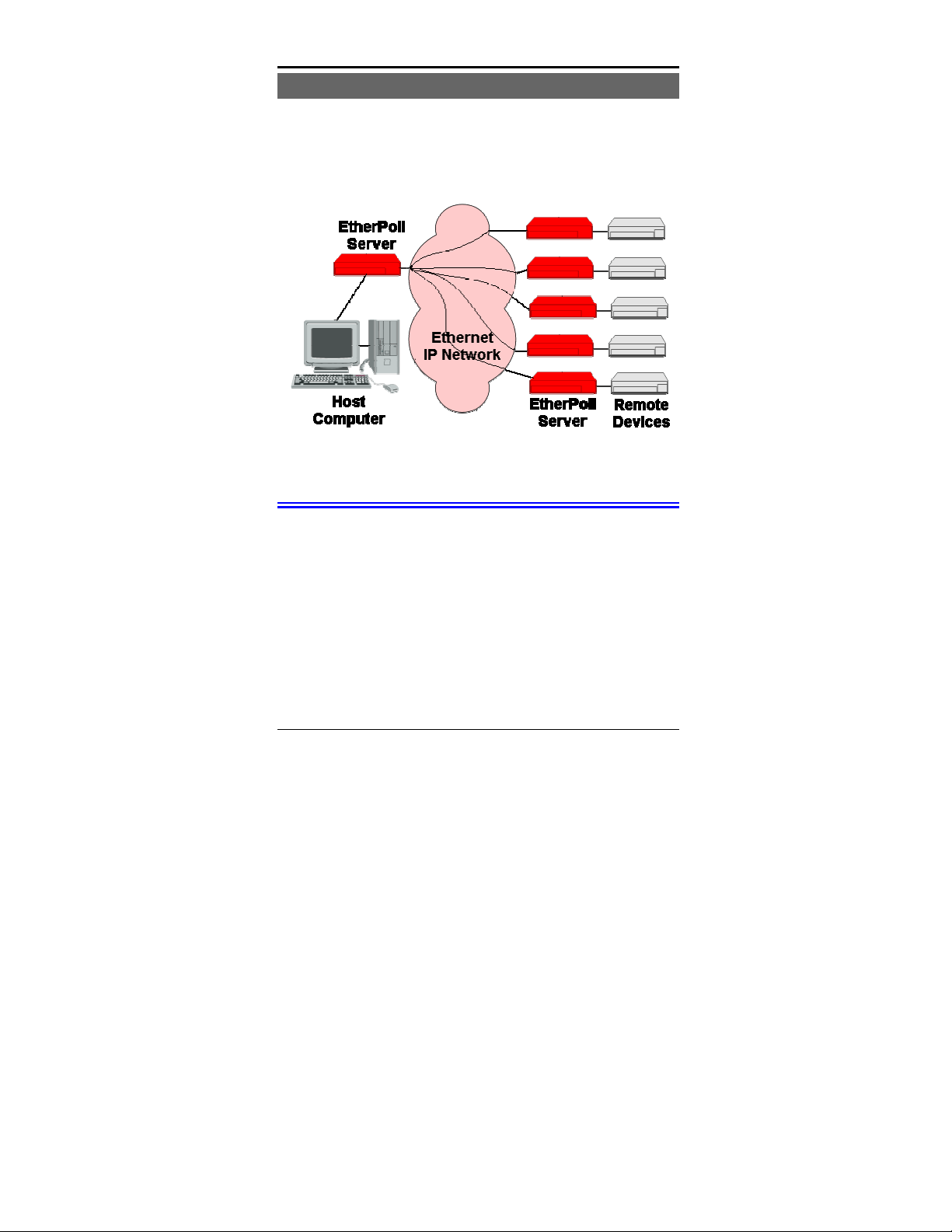
The EtherPoll is usually used in a host-to-multiple remote
polled environment.
Figure 1: Normal Mode of Operation
Normal Operating Mode (Point-to-Multi-Point)
In this mode, several EtherPolls are used. All are connected to
serial RS-232 devices. This is the equivalent to using a multidrop analog modem network… only it uses ethernet as the
medium.
• The "host" EtherPoll will be configured with IP addresses
of each “remote” EtherPoll. It is connected to a polling
host computer.
• Each “remote” EtherPoll is configured with the IP address
of the “host” EtherPoll. These are each connected to a
remote terminal unit (RTU).
3
Page 12

Etherpoll User’s Guide
• Whenever the host computer polls the remotes, a copy of
the poll block is sent to each remote in the host Etherpoll’s
address list.
• The proper remote RTU will respond to the poll through its
EtherPoll with a poll response or appropriate data blocks,
while other RTUs ignore the poll.
Point-to-Point Mode
This mode requires one pair of EtherPolls. Each EtherPoll is
connected to a serial port device, and to the LAN.
Each EtherPoll has only one IP address in its IP address list
(that of the other unit). All data received by the RS-232 port of
either EtherPoll is sent to the other EtherPoll and out its RS232 port.
Broadcast Mode (Point-to-Multi-Point)
Point-to-multi-point (broadcast) operation allows a single
EtherPoll to broadcast all incoming data to multiple EtherPolls.
Configuration is identical to the normal mode, but since nonpolling external devices are used, there is no implicit method to
control data being sent back to the host unit. For this reason, it
is normally used in “outbound broadcast data only”
applications.
Normal Mode with Backup Polling Host
This mode is also similar to the normal mode, but allows a
redundant polling host computer to monitor all data traffic, and
take control for fail-safe operation should the master host fail.
Configuration changes from normal mode are simple. Each
remote EtherPoll would have both the master and backup host
EtherPoll IP addresses in its IP address list. The master host
4
Page 13

Introduction
would also have the backup host Etherpoll address in its IP
address list.
Each remote EtherPoll sends its data to both the master and
backup polling host. If the master host fails, the backup host
should be programmed to take over the polling function. It
would sense a failure by noting that master host polls are
absent.
Other Features
UDP/IP Protocol
The EtherPoll uses the UDP/IP protocol. This is much more
efficient for a polling system than TCP/IP. Since most polled
SCADA systems use protocols that are error corrected, the
transport (EtherPoll IP network) doesn’t need to provide an
additional layer of error correction overhead.
Protocol Independent
The EtherPoll works well with any byte oriented asynchronous
SCADA protocol. It does not require getting “into” the
protocol blocks.
Protocol Conversion
The RS-232 device at the client end and the device at the server
end of a link do not have to use the same communications
parameters on the RS232 link (speed, parity, flow control). The
EtherPolls will convert the data to the correct parameters at
each end.
Upgradeable Firmware
Firmware upgrades are downloadable to the EtherPoll. The
utility program required for this, and the actual firmware
upgrades, are available from your dealer.
5
Page 14
Etherpoll User’s Guide
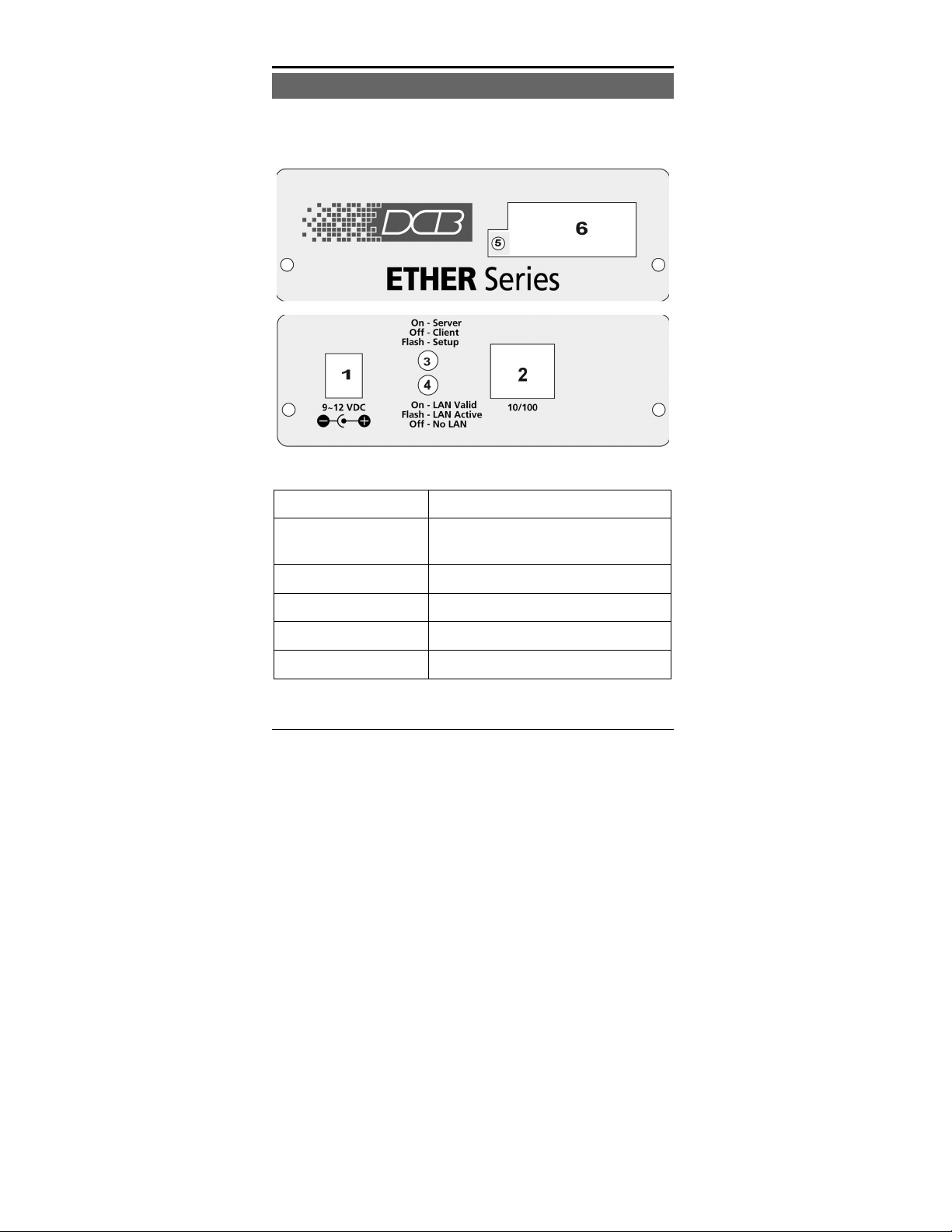
Physical Details
The EtherPoll front and rear panels are shown below.
Figure 1: EtherPoll
1
2
3
4
5
6
6
Power port
10/100Base-T
port
Red LED
Red LED
Green LED
RS-232 Port
Connect the power adapter here.
Connect LAN cabling here.
Client/Server/Setup Indicator
LAN Activity Indicator.
Connection Indicator.
DE-9 (DB-9) RS-232 Interface.
Page 15

Introduction
Configuration Switch
There is a momentary action push button switch on the right
side of the unit behind a small hole. Pressing this switch places
the unit in configuration mode and is used only when
configuring the EtherPoll via the serial port, as explained in
Chapter 3 - Configuration. Return from configuration mode by
exiting the configuration menu or by power cycling the unit.
This switch may be depressed with a tiny screw driver or stiff
wire. (A straightened paper clip works nicely).
7
Page 16

Etherpoll User’s Guide
LED Indicators
There are two red LED indicators on the rear panel adjacent to
the LAN connector and one green LED indicator on the front
panel near the 9-pin serial connector.
Rear Panel LED Indicators
• The lower red LED is the Ethernet Status indicator. It is lit
when there is a valid 10/100BaseT Ethernet connection.
This LED flashes with activity on the Ethernet (even if the
activity isn't directly to this unit).
• The upper red LED is multi-function indicator. The
different states indicated by these LED are described
below.
Red LED
Indication
OFF Normal Mode
ON Not Used
Rapid Flashing Setup Mode
Irregular Flashing Power On Self Test
8
Status Description
-or-
Firmware Download
Page 17

Introduction
Front Panel LED Indicators
• There is one front panel green LED indicator. This
corresponds to Port 1 status.
• This LED is a multi-function indicator. The different
states indicated are described below.
Green LED
Indication
OFF Pin 6 input is low and
ON Not Used
Flashing Pin 6 is high or tied
Status Description
not forced high by the
configuration
high by the
configuration
9
Page 18

Etherpoll User’s Guide
Package Contents
You should find the following items packaged with your
EtherPoll:
• The EtherPoll Unit
• Power Adapter
• This User’s Guide
If any of the above are missing, contact your dealer
immediately.
Software Requirements
The EtherPoll supports the following Ethernet protocols.
• UDP/IP
• TCP/IP
• ARP
• ICMP
• TELNET
• SNMP
It may be configured using any terminal or terminal emulation
software on a PC. Any standard telnet program may be used to
telnet to the EtherPoll for configuration, or any standard web
browser may be used for configuration once the EtherPoll has a
valid IP address configured.
10
Page 19

Chapter 2
Installation
This Chapter details the LAN installation
process for the EtherPoll.
Overview
For Telnet Mode or Web Browser Mode configuration, LAN
installation is performed before configuration. There must also
be a valid IP address in the unit prior to configuration with
these methods. The default value may not work with your
network.
If you use Terminal Mode configuration, then the configuration
should be performed prior to LAN installation. See Chapter 3
for details.
LAN Installation
1. Connect the Network Cable
• The EtherPoll network interface is auto-sensing. Simply
connect your network cable to the appropriate connector on
the EtherPoll panel.
2. Connect the Power Adapter Cable
Plug in the power adapter cable. After about a 4 second boot
process the EtherPoll is ready for operation.
11
Page 20

Etherpoll User’s Guide
3. Connect the Serial Port Device
Connect the serial port device to the serial port on the
EtherPoll. If connecting to a PC 9-pin port, a cross-over
(null modem) cable is required. See the Appendix for wiring
details.
Then apply power to the serial port device.
12
Page 21

Configuration
Chapter 3
Terminal/Telnet
Configuration
This Chapter describes how to configure the
EtherPoll using Terminal, or Telnet mode.
Web Browser mode configuration is detailed
in Chapter 4.
Overview
The EtherPoll can be configured using any of the following
methods:
• Web Browser - After installing the EtherPoll in your
LAN, use your Web Browser for configuration. See
Chapter 4 - Browser Configuration for details.
• Terminal Mode - Use a serial cable connection and a
communication program. The advantage of this method is
that you give the EtherPoll a compatible IP Address prior
to installation in your network.
• Telnet Mode - After installing the EtherPoll in your LAN,
connect to it using Telnet.
Both Terminal and Telnet modes provide the same user
interface.
13
Page 22

Etherpoll User’s Guide
Terminal Configuration
Terminal configuration requires the following:
• PC with terminal emulation program, or a dumb terminal.
• Serial cable to connect the PC to the EtherPoll. See the
Appendix for cable requirements. A Crossover (null
modem) cable is required when using a 9 pin PC port.
Procedure
1. Connect the EtherPoll to your PC or terminal.
2. Connect the EtherPoll to the power supply.
3. Press the configuration setup switch momentarily. It is
located on the side of the EtherPoll and accessed through a
small hole. Use a small pen or paper clip to access the
switch.
4. Configure the terminal program with the following settings.
Setting Value
Flow control protocol None
Speed 9600
Data 8 bits
Parity None
Stop Bit 1
5. Connect your terminal program to the appropriate port
(e.g. COM 1).
14
Page 23

Configuration
6. The configuration program should now start and after a
few seconds display a sign-on screen.
If nothing appears on your screen, press ESC.
Refer to Terminal/Telnet Interface on page 17 for details
on using the configuration program.
Telnet Configuration
NOTE: For telnet to work, there MUST be compatible IP
addresses in both the PC and the EtherPoll!
1. Install the EtherPoll into your LAN as described in Chapter
2. Ensure that the EtherPoll is powered on.
2. Connect to the EtherPoll with the command:
telnet IP_Address Port_number
Where:
IP_Address is the IP address of the EtherPoll
Port_number (for configuration) is 8000.
For example, if the default IP address had not been
changed, then you would enter the command:
telnet 192.168.1.1 8000
If you can't connect
If the EtherPoll does not respond, check the following:
• The EtherPoll is properly installed, LAN connections
are OK, and it is powered ON.
• Check that your PC is using a compatible IP Address
and Network Mask.
In Windows, the IP Address and Network Mask can be
checked by using Control Panel-Network to examine the
15
Page 24

Etherpoll User’s Guide
Properties for the TCP/IP protocol. If your PC is NOT
using an IP Address within the range 192.168.1.2 to
192.168.1.254, with a Network Mask of 255.255.255.0,
then it will not connect to the default EtherPoll IP
address.
3. Refer to the following section for details on using the
configuration program.
16
Page 25

Configuration
Terminal/Telnet Interface
The Signon screen displays the version number.
EtherPoll V4.0
------------------------------- Device Name: 0009AA04A9E
Physical Location: Head Office
Configuration setup.
[Press any key to continue]
Pressing any key will then take you to the Main Menu.
EtherPoll Main Menu
----------------------------------------- 1 Set Local & Remote IP Address,
Subnet Mask, and Gateway Address
2 Set Manager/Telnet IP Address
3 Serial Port Configuration
4 Advanced Configuration
5 Display Configuration Settings
Z Zero IP Activity Counts
6 Reset Configuration to Default
7 Save and Exit
0 Exit without Saving
Choose a Number => 1
Each of these menu options is explained in the following pages.
17
Page 26

Etherpoll User’s Guide
Entering Data
Enter the number of the field you wish to change, followed (on
the same line) by a space and the data for that field.
Example
On screen one, to set the IP address (field 1) to 192.168.1.10
=>1 192.168.1.10
Menu Options
Main Menu Option 1. Setting IP Addresses
Selecting 1 (
Mask, Gateway Address
1. Set Local & Remote IP Address, Subnet
) from the Main Menu will result in a
screen which looks like the following.
LOCAL UNIT CONFIGURATION:
Local Address: 205.166.54.212 Serial NO:
00:09:AA:A9:46:00
Gateway Address: 205.166.54.33 Subnet Mask:
255.255.255.0
Name of Contact Person: Supervisor
Device Name: SSA94600
Physical Location: Head Office
Listen on Port: 3000
IP Fragmentation: ALLOWED
SET LOCAL UNIT CONFIGURATION:
1 Local IP Address
2 Show Remote IP Addresses
A Add Remote IP Address
18
Page 27

Configuration
D Delete Remote IP Address
3 Gateway IP Address
4 Subnet Mask
5 Name of Contact Person
6 Device Name
7 Physical Location
8 Port Number
9 IP Fragmentation [0=ALLOWED, 1=NOT ALLOWED]
0 -- Return to previous menu
Enter Command => 0
1. Local IP Address
The IP address of this EtherPoll device on your LAN. The
default IP Address is 192.168.1.1
2. Show Remote IP Address List
Display a list of all configured remote Etherpoll IP addresses.
A. Add Remote IP Address
Add a remote IP address to the address list.
D. Delete Remote IP Address
Delete a remote IP address from the address list.
3. Gateway IP Address
If the remote EtherPoll is not on the same LAN, then the
gateway to the other LAN must be entered here.
4. Subnet Mask
The network mask indicates what class of TCP/IP network you
have. The default value is for a class “C” network, with up to
19
Page 28

Etherpoll User’s Guide
255 users. This value should work in small networks. If in
doubt, consult your network administrator.
5. Name of Contact Person: Supervisor
This is a text field. It can be used to store the name of the
person responsible for the Serial Port Device.
6. Device Name
This is a text field. It can be used to store a descriptive name
for the device.
7. Physical Location
This is a text field. It can be used to store the location of the
device.
8. Port Number
This is the UDP/IP port number the EtherPoll uses to send and
receive data. The default is port 3000.
9. IP Fragmentation
Allow IP fragmentation [0=ALLOWED, 1=NOT ALLOWED]
sets the EtherPoll to either allow or disallow the IP network to
fragment packets. If set to “NOT ALLOWED”, the EtherPoll
will not fragment outgoing blocks.
20
Page 29

Configuration
Main Menu Option 2. Set Manager/Telnet IP Address
Selecting (2) from the Main Menu will result in the following
screen.
Entry Manager_IpAddr
***** ***************
1. 000.000.000.000
2. 000.000.000.000
3. 000.000.000.000
4. 000.000.000.000
MANAGER SETUP:
set Entry_Number IP_Address
clear Entry_Number
0 --Return to main menu.
EXAMPLE:
to set entry #3 to IP address=138.239.0.24,
=> set 3 138.239.0.24
to clear entry #2 IP address,
=> clear 2
Enter Command =>
This screen shows a table containing four (4) entries. By
default, all entries are blank. These entries provide a security
feature. Only a user at one of the IP addresses shown can
configure the EtherPoll. (All users on the LAN can still access
the EtherPoll, but not configure it.)
If the entries are blank, then any user on the LAN can
configure the EtherPoll.
Entries in the table cannot be edited, but commands are
provided to insert (SET) and delete (CLEAR) entries.
21
Page 30

Etherpoll User’s Guide
Main Menu Option 3. Serial Port Configuration
Selecting (3) from the Main Menu will result in the following
screen.
PORT CONFIGURATION:
Flow Control: RTS/CTS
Baud Rate: 9600
Data: 8 Bits Parity: NONE Stop: 1 Bit
Pin 6 Control: FORCED ON
SET PORT CONFIGURATION:
1 Flow Control [0=None, 1=XON/XOFF, 2=RTS/CTS]
2 Baud Rate [0=230400, 1=115200, 2=57600,
3=38400, 4=19200,
5=9600, 6=4800, 7=2400, 8=1200,
9=600, 10=300]
3 Parity bit [0=None, 1=Odd, 2=Even]
4 Data bits [0=7bits, 1=8bits]
5 Stop bits [0=1bit, 1=2bits]
6 Pin 6 Control [0=From Interface, 1=Forced ON]
0 -- Return to previous menu.
EXAMPLE: To set the baud rate to 19200
=> 2 4
Enter Command => 0
This screen allows you to change the settings for the RS232
link. The settings used should match the device connected to
the serial port of the EtherPoll.
Flow Control
The choices are “None”, “XON/XOFF”, and “RTS/CTS”.
Baud Rate
Speeds between 300 bps and 230.4Kbps are supported.
22
Page 31

Configuration
Parity
The choices are “None”, “Odd”, or “Even”.
Data Bits
The choices are 7 or 8.
Stop Bits
The choices are 1 or 2.
Pin 6 Control
The choices are [0=From Interface, 1=Forced ON]. If 1, Pin 6
is forced on within the firmware. If 0, the Pin 6 signal is read
from the interface.
23
Page 32

Etherpoll User’s Guide
Main Menu Option 4. Advanced Configuration Screen
Selecting (4) from the Main Menu will display the following:
ADVANCED CONFIGURATION:
Transmit Timer: 20 ms (Mode: IDLE TIMEOUT)
Block Size: 512 Bytes
Flow OFF Buffer Level: 80% Flow ON Buffer
Level: 20%
Line Terminator Character: 13 (Dec) Transmit on LT
Char: OFF
Local Character Echo: OFF
SET ADVANCED CONFIGURATION:
1 Transmit Timer [min=1ms, max=10000ms]
M Timer Mode [0=transmit timer, 1=idle
timeout]
2 Block Size [min=1byte, max=4096bytes]
3 Flow Control OFF Buffer Level [min=1%, max=99%]
4 Flow Control ON Buffer Level [min=1%, max=99%]
5 Line Terminator Character [min=0, max=255]
6 Transmit on LT Character [0=OFF, 1=ON]
8 Client Local Character Echo [0=OFF, 1=ON]
0 -- Return to previous menu
EXAMPLE: To set the Flow OFF level to 75%
=> 3 75
Enter Command => 0
The EtherPoll has a built-in buffer to store data, and most of
these settings affect the operation of the buffer. The default
values should normally be satisfactory.
24
Page 33

Configuration
1. Transmit Timer
If set to “Transmit Timer mode”, this is the time period for
which data will be stored in the buffer before being sent. It is a
free running clock. Upon every “tic” of the clock, if there is
data in the buffer, a packet is sent out the ethernet port.
If set to “Idle Timeout mode”, this is an idle timer. Any data in
the buffer is sent out the ethernet port after the EtherPoll detects
this length of time with no incoming data on the RS-232 port.
Allowable values range from 1msec to 10,000msec (10
seconds) for both timers. Only one is used at a time. Default
value is 20 msec.
M. Timer Mode
When set = 0, the transmit timer is used. If set = 1, the idle
timeout mode is used.
2. Block Size
The maximum ethernet packet buffer size. The minimum value
is 1 byte, the maximum 4096 bytes (4 K). Note that a minimum
ethernet packet is 64 bytes, so extremely small values may be
inefficient. The timer (above) usually overrides this value.
When “block size” characters are in the buffer, a packet is sent
out the ethernet port even if timer criteria has not been met, so
the block size should be large enough to prevent fragmentation
if data blocks should not be fragmented.
3. Flow Control OFF Buffer Level
If the amount of data stored in the buffer reaches this point, and
the EtherPoll is unable to transmit the data, then no further
input will be accepted (the port will flow off).
Under normal operation, this will not happen.
25
Page 34

Etherpoll User’s Guide
4. Flow Control ON Buffer Level
Once the Flow Control OFF buffer level has been reached, the
“no-input accepted” mode will continue until the EtherPoll has
transmitted enough data to reduce the buffer contents to this
point.
5. Line_Terminator_Character
This setting is used to change the Line Terminator Character.
The Line Terminator Character causes any data in the buffer to
be transmitted immediately when the character is received,
provided the following setting (Transmit_on_LT_Char) is ON.
6. Transmit_on_LT_Char
When this setting is ON, any data in the buffer will be sent
immediately upon receipt of a Line_Terminator_Character (see
previous setting). When the setting is OFF, the
Line_Terminator_Character has no effect.
This is usually set OFF for SCADA applications.
7. Transmit Mode Filter
This setting can turn the filter function ON or OFF.
If ON, then when a CR/LF (Carriage Return, Line Feed)
character pair is received, it is converted to a CR only before it
is sent to the serial port output. CR/LF pairs are normally used
in the MS-DOS environment to mark the end of a line, but may
cause problems in other environments.
CR/NULL character pairs are also converted to a CR only. If
this setting is OFF, then no conversion is done.
This is usually set OFF for SCADA applications.
26
Page 35

Configuration
8. Client Local Character Echo
If ECHO is ON, the EtherPoll will locally echo all incoming
characters.
If ECHO is OFF, the EtherPoll will not echo characters or
transmit any status messages to the serial port. This mode
should be used if any messages from the EtherPoll would create
interference.
This is usually set OFF for SCADA applications.
27
Page 36

Etherpoll User’s Guide
Main Menu Option 5. Display Settings
Selecting (5) from the Main Menu displays a screen similar to
the following example.
LOCAL UNIT CONFIGURATION:
Local Address: 205.166.54.212 Serial NO:
00:09:AA:A9:46:00
Gateway Address: 205.166.54.33 Subnet Mask:
255.255.255.0
Name of Contact Person: Supervisor
Device Name: SSA94600
Physical Location: Head Office
Remote Port: 3000
IP Fragmentation: ALLOWED
MANAGER CONFIGURATION:
Entry Manager_IP_Addr
***** ***************
1. 0.0.0.0
2. 0.0.0.0
3. 0.0.0.0
4. 0.0.0.0
PORT CONFIGURATION:
Flow Control: RTS/CTS
Baud Rate: 9600
Data: 8 Bits Parity: NONE Stop: 1 Bit
Pin 6 Control: FORCED ON
ADVANCED CONFIGURATION:
Transmit Timer: 20 ms (Mode: IDLE TIMEOUT)
Block Size: 512 Bytes
Flow OFF Buffer Level: 80% Flow ON Buffer
Level: 20%
Line Terminator Character: 13 (Dec) Transmit on LT
Char: OFF
Client Local Character Echo: OFF
28
Page 37

Configuration
CURRENT ETHERPOLL STATISTICS:
Network RX packet count: 0
Network TX packet count: 0
Network error count: 0
Serial Port RX count: 20
Serial Port TX count: 5517
REMOTE IP ACTIVITY COUNTS
205.166.54.213: 0
205.166.54.214: 0
CURRENT ETHERPOLL CONFIGURATION:
Config Mode
[Press any key to continue]
Note that no data can be changed. Pressing any key from the
above screen will return you to the Main Screen.
All data items except the following have been explained on the
preceding pages.
Current Statistics
Network RX packet count: 0
Packets received from the ethernet interface.
Network TX packet count: 0
Packets transmitted to the ethernet interface.
Network error count: 0
Errored packets received from the ethernet interface.
29
Page 38

Etherpoll User’s Guide
Serial Port RX count: 20
Characters received into the RS-232 port.
Serial Port TX count: 5517
Characters transmitted out the RS-232 port.
Remote IP Activity counts
Displays IP address and packet count for each remote that has
exchanged data with this EtherPoll. If data has been received
from a remote that is not is the IP address list, that information
is also displayed along with the IP address of the first un-listed
IP address. (These packets are discarded.)
Current Configuration
Switch Status
Current setting of the Internal Mode Switches.
30
Page 39

Configuration
Main Menu Option 6. Reset Configuration to Default
Selecting (6) from the Main Menu will restore all values to
their default values.
If using Telnet or web browser configuration, the connection
will be lost when the EtherPoll reboots. To reconnect, you must
use the default IP Address of 192.168.1.1 or change the
EtherPoll IP address before rebooting with main menu option 7.
The preferred method is to restore defaults with menu item 6,
and then BEFORE REBOOTING, change the IP information
using submenu 1 so your PC will still be able to connect to the
EtherPoll when it reboots.
Main Menu Option 7. Save and Exit
Selecting (7) from the Main Menu will store the configuration
details in the EtherPoll, and exit the configuration program.
If using Telnet, the connection may be lost when the EtherPoll
reboots. If you have changed the IP Address, you must use the
new IP Address when you reconnect.
Main Menu Option 0. Exit without Saving
Selecting (0) from the Main Menu will exit the configuration
program without saving any data you have entered.
31
Page 40

Chapter 4
Browser
Configuration
This Chapter describes how to configure the
EtherPoll using a Web Browser.
Overview
This configuration method uses your Web Browser to configure
the EtherPoll. This provides a more user-friendly interface than
the Telnet/Terminal method.
• The EtherPoll must be installed in your LAN and have a
compatible IP address before this configuration method
can be used.
• Most Browsers will work. The only requirement is that
they support HTML tables and forms. If your browser uses
a proxy, the proxy function may need to be disabled.
Connection Procedure
To establish a connection to the EtherPoll, follow this
procedure:
1. Install the EtherPoll in your LAN as described in Chapter
2. Ensure that the EtherPoll is powered on.
2. Start your Web browser.
32
Page 41

Configuration
3. In the Address box of your browser, enter the following:
http://IP_Address
(IP_Address is the IP address of the EtherPoll)
For example, if the default IP address has not been
changed, then you would enter the command:
Http://192.168.1.1
If you can't connect
If the EtherPoll does not respond, check the following:
• The EtherPoll is properly installed, LAN connections
are OK, and it is powered ON.
• Check that your PC is using a compatible IP Address
and Network Mask.
In Windows, the IP Address and Network Mask can be
checked by using Control Panel-Network to examine the
Properties for the TCP/IP protocol.
If your PC is NOT using an IP Address within the range
192.168.1.2 to 192.168.1.254, with a Network Mask of
255.255.255.0, it will not be able to communicate with
the EtherPoll.
4. Once connected, you will see the first screen. Refer to the
following section for details on using the Web-based
interface.
33
Page 42

Etherpoll User’s Guide
Web-based Interface
The first screen is similar to Figure 2.
Figure 2: Sign on Screen
• Use the menu bar on the left to navigate to the desired
screen.
• On-line help is available on each screen.
• Each screen is explained in the following sections.
34
Page 43

Configuration
Port Configuration Screen
Figure 3: Port Configuration Screen
This screen allows you to configure the Serial Port on the
EtherPoll. The settings used should match the device connected
to the serial port of the EtherPoll.
• Consult the documentation of your serial port device to
determine what settings to use.
• Pin 6 Control Mode, See Section 5. Operation for details
on how to set this. Normally “From Interface”.
35
Page 44
Etherpoll User’s Guide
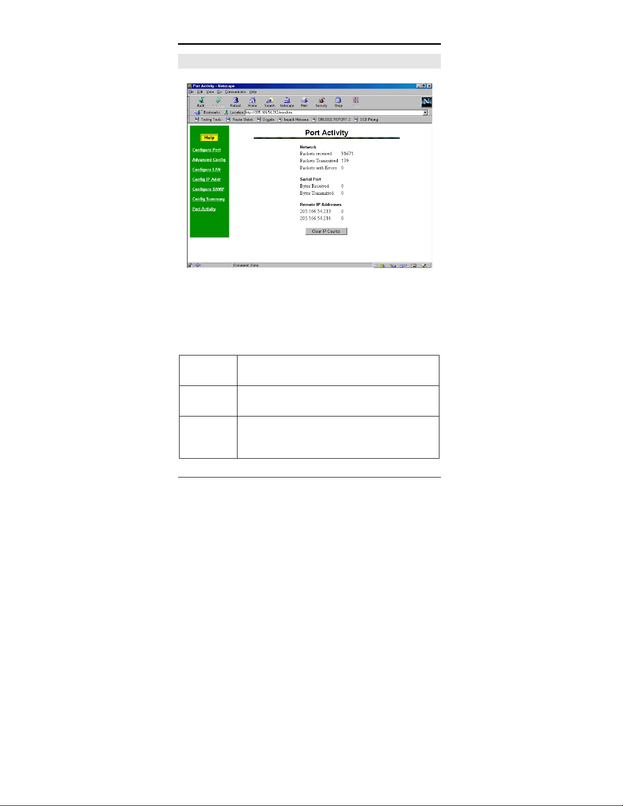
Port Activity Screen
Figure 4:Port Activity Screen
This screen displays details about the data currently being
transmitted or received, either through the LAN or Serial port.
The display is updated every 10 seconds.
Data - Network
Packets
received:
Packets
Transmitted
Packets with
Errors
36
Number of packets received by the EtherPoll
through the LAN connection.
Number of packets transmitted by the EtherPoll
through the LAN connection.
Number of packets transmitted or received by
the EtherPoll through the LAN connection which
contained errors. (Should be zero)
Page 45

Data - Serial Port
Configuration
Bytes
Received
Bytes
Transmitted
Data – Remote IP Addresses
Remote IP
Address
Data- Un-Listed Remote IP addresses
Unlisted
Remote IP
Address
Number of bytes received, through the serial
(RS232) connection, from the Serial port device
Number of bytes transmitted through the serial
(RS232) connection to the Serial port device (or
PC, if in Client mode).
Number of bytes transmitted to that address
If data has been received from a remote that is
not is the IP address list, that count is also
displayed along with the IP address of the first
un-listed IP address. (The incoming packets
are discarded.)
37
Page 46

Etherpoll User’s Guide
Advanced Configuration Screen
Figure 5: Advanced ConfigurationScreen
These settings affect the Etherpoll's internal buffer, which is
used for temporary storage of data, and how some characters
are processed. These values strongly affect efficiency and
throughput. They may be “tuned” for your application.
Transmit
Timer
(msec)
38
When in Timer Mode, the maximum time period
data will be stored in the buffer before being sent.
When in Idle Timeout Mode, the time that the
RS-232 port must be idle before data in the buffer
is transmitted to the ethernet port.
Allowable values range from 1ms to 10,000ms
(10 seconds). Default is 20 ms.
Page 47

Configuration
Timer Mode When set for Transmit Timer, a free-running
clock triggers the EtherPoll to send a packet of
data at every tic if there is any data its buffer.
When set for Idle Timeout a packet of data is
transmitted to the ethernet when there is not RS232 data received for the specified idle time and
any data is in the buffer.
Block Size
(bytes)
Flow OFF
buffer level
(%)
Flow ON
buffer level
(%)
Line
terminator
character
(decimal)
The size of the ethernet packet buffer. The
minimum value is 1 byte, the maximum 4096
bytes (4 K). ). Note that ethernet packets are at
least 64 bytes long, so extremely small values are
quite inefficient.
If the amount of data stored in the buffer reaches
this point, and the EtherPoll is unable to transmit
the data, then no further input will be accepted
from the serial port. The RS-232 port will be
“flowed off”. Under normal operation, this will
not happen.
Once flow control has stopped input characters,
the "no-input accepted" mode will continue until
the EtherPoll has transmitted enough data to
reduce the buffer contents to this point.
Enter the ASCII/ANSI number (1..128) to
represent the Line Terminator Character. The
Line Terminator Character causes any data in the
buffer to be transmitted immediately when the
character is received, provided that the following
setting (Transmit on LT Char) is ON. The
default value is 0x13, a carriage return character.
39
Page 48

Etherpoll User’s Guide
Transmit on
LT char
Transmit
filter mode
Local
character
echo
When this setting is ON, any data in the buffer
will be sent immediately upon receipt of a Line
Terminator Character (see above).
When this setting is OFF, the Line Terminator
Character has no effect. This should normally be
set to OFF for SCADA networks.
This setting turns the filter function ON or OFF.
If ON, when a CR/LF (Carriage Return, Line
Feed) character pair is received, it is converted to
a CR only. CR/LF pairs are normally used in the
MS-DOS environment to mark the end of a line,
but may cause problems in other environments
which expect a CR only.
CR/NULL character pairs are also converted to a
CR only. If this setting is OFF, then no
conversion is done. It is normally OFF for
SCADA networks.
If ECHO is ON, all characters received from the
serial port are echoed back out that port when
connected.
If ECHO is OFF, the EtherPoll will not echo
input characters. This mode should be used if any
messages from the EtherPoll would create
interference with other software.
40
Page 49

Configuration
LAN Configuration Screen
Figure 6: LAN Configuration Screen
This screen allows you to set all data relating to your LAN.
• EtherPoll IP Address and network mask are required.
• Default Gateway Required if operating through a router.
• Administrator Access Rights data is required if you wish
to restrict access to the EtherPoll's configuration data. If
any values are entered, then only those PCs will be able to
access the EtherPoll and change the configuration.
41
Page 50

Etherpoll User’s Guide
• Remote Device Listen Port is the UDP port number with
which this EtherPoll will communicate.
• IP Fragmentation may be disallowed based upon this
configuration.
Data - EtherPoll
IP Address: The IP address of this EtherPoll device on your
LAN in dotted decimal format. The default IP
Address is 192.168.1.1
Note: If you change the IP Address, the
connection will be lost when you "Save". You
must reconnect using the new IP Address.
Network
Mask:
Gateway IP
Address:
Data - Administrator Access Rights
Manager IP
Address
[1] to [4]
Data - Remote Device
42
The network mask indicates what class of
TCP/IP network you have. The default value
(255.255.255.0) is for a class "C" network, with
up to 255 users. This value should work in small
networks. If in doubt, consult your network
administrator.
If your LAN contains a router, enter the IP
Address of the Router. Otherwise, leave this
value at 0.0.0.0
Enter the IP Addresses of the PCs which you
wish to have access to the EtherPoll
configuration data. If these are left blank
(default) then all PCs have access.
Page 51

Configuration
Remote IP
Port
Data – IP Fragmentation
Remote IP
Port
This is the port with which the EtherPoll will
send and receive data. The default is 3000.
If set to “NOT ALLOWED”, the EtherPoll will
not fragment data blocks, and will set the “don’t
fragment” bit in ethernet packets. If set to
“ALLOWED”, fragmentation is allowed on
EtherPoll ethernet packets and the “don’t
fragment” bit is not set.
43
Page 52
Etherpoll User’s Guide
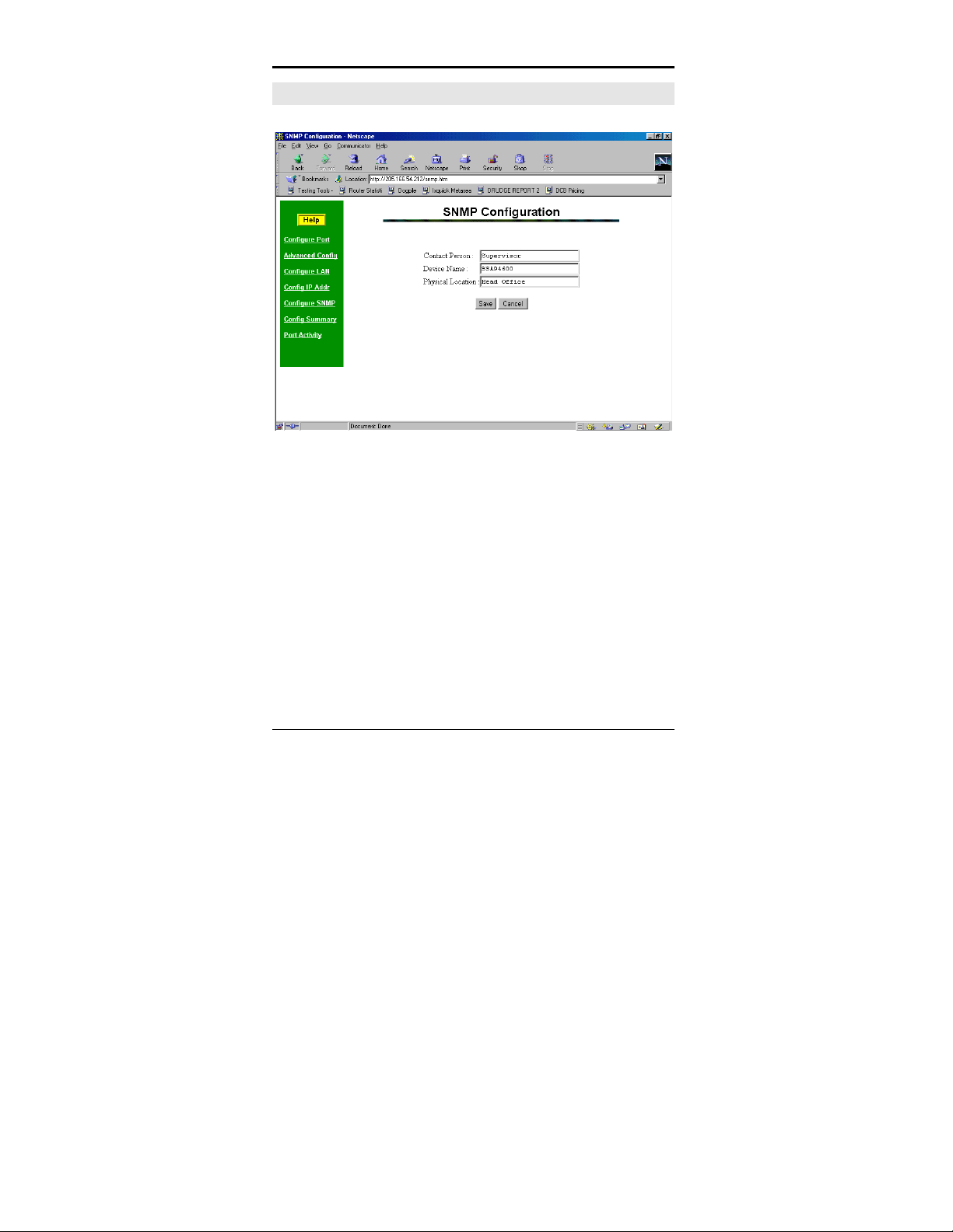
SNMP Configuration Screen
Figure 7: SNMP Configuration Screen
Overview
This screen may be ignored if SNMP is not used.
These are text fields, commonly used in SNMP (Simple
Network Management Protocol) Programs to identify this
device when browsing the network.
These values have no effect on the operation of the EtherPoll.
Other standard MIB values are returned to the SNMP manager
along with this information.
44
Page 53

Configuration
Data
Contact Person This text field can be used to store the name
of the person responsible for the Serial Port
Device.
Device Name This can be used to store a descriptive name
for the device.
Physical Location This can be used to store the location of the
device.
45
Page 54

Etherpoll User’s Guide
Configuration Summary Screen
Figure 8: Configuration Summary Screen
Operation
• This screen displays all current settings for this
EtherPoll
• Clicking the "Set to Defaults" button will restore ALL
values to their factory default values.
When this is done, the EtherPoll will reboot, and the
46
Page 55

Configuration
existing connection will be lost. You must reconnect
using the default IP Address of 192.168.1.1.
Data
All values on this screen are described in earlier sections.
47
Page 56

48
Page 57

Chapter 5
Configuration Security
This section discusses configuration options
that restrict configuration .
Overview
The EtherPoll uses the industry standard UDP/IP protocol.
Since this is a well known standard, its security vulnerabilities
are also well known and may be exploited. Several EtherPoll
options are available to enhance the inherent security of your
EtherPoll network. However, since network security is a
moving target and absolute security is never achievable, every
network installation should be designed and implemented with
care to minimize security risks in a way that is appropriate for
the application and perceived risks.
The EtherPoll may be configured with several levels of security
configuration and authentication. These restrict the ability of
an unwanted user from changing the configuration of the
EtherPoll. They do not restrict the ability of a remote device to
deliver packets to the EtherPoll's data port.
49
Page 58

Etherpoll User’s Guide
At the level 0, any workstation may be used to configure the
EtherPoll via either telnet or web browser configuration. Level
1 restricts configuration to workstations claiming to be from
one of four IP addresses previously stored in the EtherPoll.
Either web-based or telnet configuration is allowed. Level 2
disables remote configuration using web browser, telnet, or
SNMP in any combination. Level 3 requires a user name and
password for remote configuration. Combinations of Level 2
and Level 3 are possible (ie. One may disable web browser
configuration and SNMP and require a username/password for
telnet configuration. The most secure method would be to
disable all remote configuration.
The EtherPoll may always be configured using the direct
connected terminal method. This requires physical access to
the hardware, and pressing the configuration button while a
terminal (or PC) is connected to the serial port.
Level 0:
No specific security configuration is required. Make sure that
no IP addresses have been entered in menu item 2, "Set
Manager/Telnet IP Address" screen (or the "Administrator
Access Rights of the web browser "Configure LAN" screen).
Also, any user name/password pairs that may have been entered
on the terminal configuration/telnet "Security Configuration"
screen should be cleared.
50
Page 59

Security
Level 1:
Using any configuration method, configure Administrator
Access IP addresses. Enter the IP addresses that should have
the ability to change the EtherPoll configuration. If configuring
this remotely, insure that the workstation you are using is one of
the valid addresses.
Level 2:
Using telnet or direct connection configuration, selectively
enable or disable remote configuration via Telnet, via web
browser, and SNMP. This setting may not be performed from
the web configuration screen.
Level 3:
Configure Level 1 and Level 2 security as needed. Using the
telnet or direct connection configuration, enter up to three user
name and password pairs. If there is at least one user name in
this list, then a password prompt will be issued upon
establishing a telnet configuration session.
There may be up to 3 user names and passwords configured. If
no users are configured, password protection is disabled. User
names and passwords are limited to 8 characters each. There is
a six failed login attempt limit. After six failed attempts in a
row, the unit will lock out all logins for a period of about 10
minutes.
Each user name has an associated user ID or index. The
user with ID 1 is considered the master user. It has the
51
Page 60

Etherpoll User’s Guide
ability to change the other user names and passwords.
The other two user ID's are limited to only changing their
own user name and password. All users may modify any
other system parameters.
The serial interface is not subjected to user login since it
requires physical access to the unit.
SECURITY CONFIGURATION:
Web Configuration: ENABLED
Telnet Configuration: ENABLED
SNMP Agent: ENABLED
Index UserName Password
----- -------- --------
1:
2:
3:
SET SECURITY CONFIGURATION:
1 Disable Web Configuration [0=ENABLED, 1=DISABLED]
2 Disable Telnet Configuration [0=ENABLED, 1=DISABLED]
3 Disable SNMP Agent [0=ENABLED, 1=DISABLED]
4 Set User ID and Password [index userid password]
5 Clear User ID and Password
0 -- Return to previous menu
EXAMPLE: To set User ID 1 to root, password toor
=> 4 1 root toor
Enter Command =>
Security Configuration Screen
52
Page 61

Chapter 6
Operation
This Chapter explains how to use the
EtherPoll, once it is installed and configured.
Normal Mode
• All EtherPolls must be connected as described in Chapter
3. Configuration is complete, and serial port configurations
match the associated serial port device (Polling host or
RTU). LAN configuration is complete with appropriate IP
addressing.
• Power up all EtherPolls and associated hardware.
• Start the polling program on the polling host computer. It
should automatically poll each RTU connected to an
EtherPoll whose IP address was stored during
configuration of the host EtherPoll.
• Pin 6 input must be HIGH or Forced ON for the unit to
send and receive packets. When pin 6 is LOW, the serial
interface turns OFF the pin 4 (DTR) and 7 (RTS) output
signals.
53
Page 62

Etherpoll User’s Guide
Broadcast Mode
• Install and connect the EtherPolls and Serial Port Devices
as described above.
• Send some characters from a PC or terminal device
connected to the host EtherPoll to its RS-232 port.
• The characters should appear on the RS-232 port of all
EtherPolls whose addresses are configured in the host
EtherPoll IP address list.
• Pin 6 input must be HIGH or Forced ON for the unit to
send and receive packets. When pin 6 is LOW, the serial
interface turns OFF the pin 4 (DTR) and 7 (RTS) output
signals.
Point-to-Point Mode
• This is similar to the above operations, however only ONE
remote IP address is configured into each EtherPoll.
• Pin 6 input must be HIGH or Forced ON for the unit to
send and receive packets. When pin 6 is LOW, the serial
interface turns OFF the pin 4 (DTR) and 7 (RTS) output
signals.
54
Page 63

Chapter 7
Troubleshooting
This chapter outlines some problems that may
occur during installation or operation and
some possible solutions to them.
If you follow the suggested troubleshooting steps and the
EtherPoll still does not function properly, please contact your
dealer for further advice.
Hardware Problems
Before anything else, check that all cables are wired
correctly and properly connected. If connecting to a 9 pin
PC port, a crossover (null modem) cable is required.
P: All the EtherPoll’s LEDs are off.
S: Check the power supply or power connection.
P: When using 10/100Base-T cabling, the EtherPoll unit does
not work.
S: Check the Hub’s link LED for the port to which EtherPoll is
connected. If it is off, make sure the network cable
between the EtherPoll and hub is in good condition.
55
Page 64

Etherpoll User’s Guide
Can't Connect via the LAN
P: Can't connect to the EtherPoll using Telnet or Web
Browser.
S: Check the following:
• Start troubleshooting from a known state. Power the
EtherPoll OFF and ON to reboot.
• “Ping” the EtherPoll to see if it responds. From the
Windows command prompt or “Run” dialog box, use
the command:
ping IP_Address
Where IP_Address is the IP Address of the
EtherPoll (e.g. ping 192.168.1.1 ). If it does
not respond, then check all LAN connections. If the
LAN connection are OK, the problem is in the LAN
addresses or routing. You should be able to ping all
EtherPolls. The most common problem cause is
incorrect IP addressing. Make sure the
workstation and EtherPolls have compatible IP
addresses.
• If using a LAN without routers, you can connect to the
EtherPoll ONLY IF your PC and the EtherPoll are
using IP Addresses from the same address block. The
EtherPolls default IP Address (192.168.1.1) requires
that your PC is using an address from the address
block 192.168.1.2 to 192.168.1.254, and a Network
Mask of 255.255.255.0. If a router is between the
devices, a gateway address must be configured in both
devices.
56
Check your PC's IP Address using Control Panel -
Page 65

Troubleshooting
Network - TCP/IP (Adapter) Properties or Windows98
WINIPCFG.EXE . If you are using a different Address
block, use Terminal Mode configuration to set a
compatible IP Address in the EtherPoll.
• It may be that your "arp table" contains invalid entries.
You can clear the "arp table" by rebooting, or, on
Windows95 , by typing the following command at the
command prompt or Run dialog box.: arp -d
• Check that you have used the correct port address. The
default address is “3000” for normal operation and
“8000” for configuration.
• MOST EtherPoll connection problems are due to
incorrect RS-232 wiring. The second most common
errors are incorrect IP addressing on either the
EtherPoll or on the PC used for testing.
• In some cases, “smart” hubs and switches must be
power-cycled to clear their internal arp cache. This is
often a problem on test bench setups where IP
addresses are moved between different equipment or a
unit is moved between ethernet switch receptacles.
57
Page 66

Etherpoll User’s Guide
Other Problems
P: Can’t run the configuration program using a serial cable
connection.
S: Check that:
• The communication parameters are set properly.
• Disconnect and reconnect the power supply to the
EtherPoll.
• Power is available... a LED is on.
• The terminal program is operating properly. Try a
loopback connector at the EtherPoll end of the cable to
verify program operation and the proper COM: port.
• The most common problems causing this symptom
are incorrect RS-232 wiring or the Windows
Hyperterm program not operating correctly.
P: The “host” EtherPoll doesn’t automatically send data to the
“RTU” EtherPolls.
S: Check that:
• A workstation on the host EtherPoll LAN can
successfully ping all remotes.
• If a firewall is between the EtherPolls it must pass the
ports in use for UDP.
• The EtherPolls should either be configured for “Pin 6
Control” forced ON or the interface must be wired in
such a way that that pin 6 is asserted.
• The “RTU’s” IP addresses were correctly entered into
the “HOST’s” EtherPoll IP Address list.
• The Gateway IP Address is set correctly.
• The Subnet Mask is set correctly.
58
Page 67

Troubleshooting
• The communication parameters between the host
computer and the local (“host”) EtherPoll match.
• The communication parameters between the serial port
RTU device and the remote (“RTU”) EtherPoll match.
P: The EtherPoll's IP Address is unknown. Is there any way of
finding it, other than using Terminal Configuration mode?
S: Follow this procedure:
• Press the configuration button.
• Connect to the EtherPoll, using a terminal and read or
change the IP address.
• Save before exiting.
• Switch the power off, and back to normal operation.
59
Page 68

Etherpoll User’s Guide
Checking Device Operation
Once the EtherPoll is installed on your Network, you can
connect to it using Telnet, to verify its operation. The procedure
is as follows.
1. Use telnet to connect to the EtherPoll with the
command:
telnet IP_Address 8000
Where IP_Address is the IP Address assigned to
the EtherPoll, and 8000 represents the Port number.
The port number is “8000” for configuration, but
“3000” is the default for normal operation. Remember
that actual data connections to the EtherPoll on port
3000 are not TCP/IP as used with telnet programs, but
are UDP/IP.
If the “Manager IP Addresses” have been entered in
the EtherPoll, then only a PC having one of those
addresses can change the configuration.
2. Choose item 5 (“Display Settings”) from the Main
Menu, and examine the data shown. See page 28 for
an explanation of each of the data items.
60
Page 69

Appendix A
Specifications
EtherPoll Specifications
• Flash Memory: 512 Kbytes
• SRAM: 256 Kbytes
• EEPROM: 512 Bytes
• LAN Buffer: 2 Kbytes
• RS-232 Buffer: 4 Kbytes
• RS-232: one male DE-9 connector
• Network: Ethernet 10Base-T/ 100Base-T
• CPU: 16 Bit
• Power: 9 to 12 VDC (260 ma) or Optional power
supplies
• Switch: Configuration
• LED: 3 multi-purpose
• Default IP address: 192.168.1.1
• Default Receive port: 3000
• Operational Temperature -40C to +70C
61
Page 70

Etherpoll User’s Guide
RS-232 PIN Assignments
The EtherPoll RS-232 port wiring is identical to a standard PC
9 pin DE-9P COM: port. It operates as a DTE device. The
chart below details signal directions and names.
Serial Port Pin Assignments
Pin Signal Name Type
1 Carrier Detect (CD) In
2 Receive (Rx) In
3 Transmit (Tx) Out
4 Data Terminal Ready Out
5 Signal Ground (GND) Power
62
6 Data Set Ready (DSR)
(Hardware controlled input.
See Section 5)
In
7 Request to Send (RTS) Out
8 Clear to Send (CTS) In
9 Ring Indicator (RI)
(Not used)
In
Page 71

Specifications
Control Signal Operation
DCD
Input, ignored
Receive Data
Input, data into the EtherPoll
Transmit Data
Output, Data from the EtherPoll The EtherPoll only transmits
when it has characters to send and it is not flowed-off with
XON/XOFF or RTS/CTS flow control.
DTR
Output. Signal is enabled when the EtherPoll has a valid signal
on input pin 6 OR pin 6 (DSR) if forced on by configuration.
When pin 6 input is LOW, the serial interface turns OFF the pin
4 (DTR) and 7 (RTS) output signals.
Signal Ground
Common ground
DSR
Input. Used for connection control. If the EtherPoll is
configured for “Hardware (Pin 6) from interface” and not
“Forced ON”, the EtherPoll only transmits and receives data
via the LAN when the signal is asserted. If configured for
“Forced ON”, the EtherPoll may send and receive data via the
LAN at any time. When pin 6 is LOW, the serial interface turns
OFF the pin 4 (DTR) and 7 (RTS) output signals.
63
Page 72

Etherpoll User’s Guide
RTS
Output. Input flow control. When the internal buffer reaches
the “Flow Off” buffer level, this signal is lowered. When the
buffer level decreases to the “Flow ON” buffer level, this signal
is raised. When pin 6 input is LOW, the serial interface turns
OFF the pin 4 (DTR) and 7 (RTS) output signals.
CTS
Input. When Flow Control is set for CTS/RTS, lowering this
signal will halt data flow from the EtherPoll RS-232 port.
Ring Indicator
Not used
64
Page 73

CABLES
Commonly used cable connections:
To PC 9-pin COM: port
Specifications
S S -1
1, 6
2
3
4
5
7
8
P C
4
3
2
1, 6
5
8
7
This null-modem crossover cable is easily made by combining
“PC-Direct” and “Remote PC” adapter hoods with a straightthrough line cord.
SR Mux Composite or Access Switch Input Port
RJ-45
1
2
3
4
5
6
7
8
BLU
ORG
BLK
RED
GRN
YEL
BRN
WHT
DE-9S
N/C
N/C
4,1,6
5
2
3
8
7
65
Page 74

Etherpoll User’s Guide
EtherPoll to Modem
Use any commercially available PC-to-modem cable.
Ethernet Cross-Over Cable
Used to connect two EtherPoll ethernet connections “back-toback” without using an ethernet hub for test purposes. Also
used to connect a EtherPoll directly to a PC’s LAN connection
for testing.
RJ-45
1
2
3
4
5
6
7
8
WHT / ORG
ORG / WHT
WHT / GRN
BLU / WHT
WHT / BLU
GRN / WHT
WHT / BRN
BRN / WHT
RJ-45
3
6
1
N/C
N/C
2
N/C
N/C
66
Page 75

Specifications
Appendix B
Advanced Operation
Information
This Appendix explains the EtherPoll's
operation in more detail. This information is
not needed in most applications.
Introduction
The EtherPoll must be configured with proper ethernet
addressing and serial port parameters. It has been used
successfully with common SCADA protocols such as Modbus
ASCII, Modbus RTU, DNP3, and other 8-bit asynchronous
protocols. This section explains how the EtherPoll operates for
the technician who needs to understand the internals in more
detail.
67
Page 76

Etherpoll User’s Guide
Description and Behavior
Ports used by the EtherPoll
The EtherPoll uses 2 ports, as follows:
Port Description
Configurable
default - 3000
8000 Provides a telnet configuration service for
EtherPoll listens at port 3000 and offers a
raw UDP connection. This port number is
configurable.
all modes.
Normal Operation Modes
In Normal Mode, the EtherPoll runs under the UDP/IP network
protocol. It will listen on a configured port number. The server
will wait for incoming data after initialization.
The EtherPoll constantly checks for data on both Ethernet and
Serial Ports.
If data from the Ethernet network is received, it will first check
for a special control symbol, filter it if found (and configured to
filter) and then send the rest of the data to the serial port.
If data from the serial port is received, it will read the data from
the serial buffer, move the data into the network buffer and
send it by ethernet when the buffer is full, when it senses an idle
timeout, or on the next tick of the transmit timer.
68
Page 77

Specifications
The data being sent via ethernet is packaged into UDP packets
and a separate copy is sent to each IP address in the EtherPoll’s
IP address list.
Point - to - Point Mode
EtherPolls configured for Point-to-Point mode function the
same. The only difference between the “normal” operation and
point-to-point is the number of IP addresses in the IP address
list. For point-to-point operation, there is only one address in
the list (the other unit’s).
Broadcast Mode
Broadcast mode is also identical to “normal” mode. There is
simply no polling taking place over the network.
Transmit Conditions
The EtherPoll will transmit an ethernet packet of data whenever
one of the following conditions is met…
• Timer is up. In Timer Mode, a free running clock triggers
a transmission when it ticks if there is data in the buffer.
• Idle time is up. In Idle Timeout mode, a (configured) time
period elapses with no incoming data if there is data in the
buffer.
• Transmit Buffer full.
• LT Character is encountered if Line Terminal Function is
ON.
69
Page 78

Etherpoll User’s Guide
Application Notes
Protocols
The EtherPoll is protocol-transparent. It has been successfully
used with many 8-bit asynchronous protocols. However, some
protocols work best with specific settings. If in doubt, call
Tech Support for additional information on your application.
Quick Set-Up
An example configuration for a test bench setup is available on
the DCB web site at
http://www.dcbnet.com/notes/0102etherpoll.html . Other
applications notes are available at the same web site at
http://www.dcbnet.com/apnotes.html .
70
Page 79

Specifications
Appendix C
RS-422/ RS-485
Interface
This Appendix describes the RS-422/485
interface. This interface option may be
jumper configured in the field or preconfigured at the factory.
Introduction
The 9-pin serial connector on the EtherPoll may be used for
either RS-232 or RS-422 (4-wire RS-485 point-to-point)
operation by changing internal jumpers.
Changing the Setting
Remove the main board from the case by removing two screws
from the rear panel. There is a row of jumpers and three rows
of pins adjacent to the serial connector.
RS-232 Setting
ALL jumpers should be placed in the positions nearest the
board edge.
RS-422/4-Wire RS-485 Setting
71
Page 80

Etherpoll User’s Guide
ALL jumpers should placed in the positions furthermost from
the board edge.
RS-422 / 4-Wire RS-485 Interface Pinout
Serial Port Pin Assignments
Pin Signal Name Type
1 No Connection N/A
2 No Connection N/A
3 Receive Data (Rx-) In
4 Transmit Data (Tx-) Out
5 Signal Ground (GND) N/A
6 No Connection N/A
7 No Connection N/A
8 Receive Data (Rx+) In
9 Transmit Data (Tx+) Out
72
 Loading...