

Page 1
JUNIOR
USER MANUAL
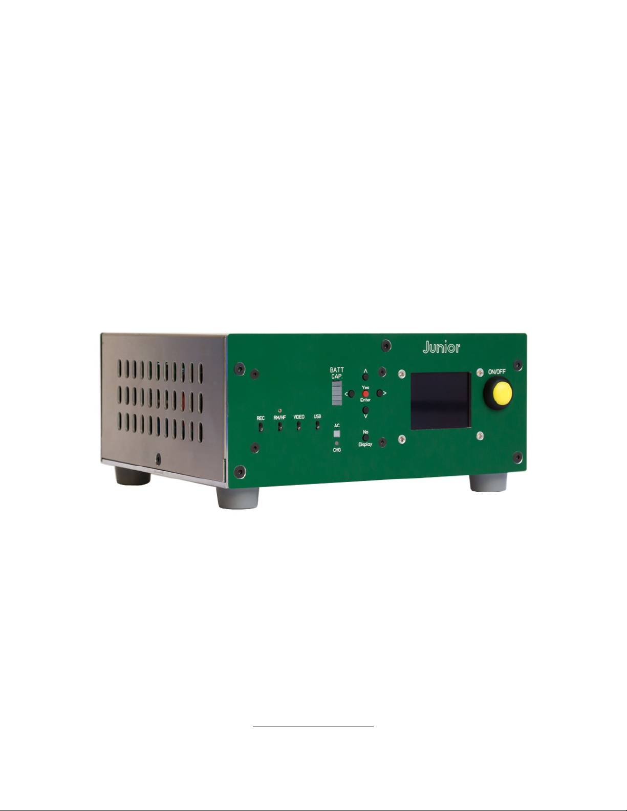
Junior is a light and compact power station for small sound trolleys
DC Audiovisuel © Feb. 2019
www.dcaudiovisuel.com
Page 2
A) Inputs
Junior can be powered from 90-250V AC line voltage through an IEC
connector, or different battery types through a XLR4M connector. When
both sources are connected to Junior, the AC line voltage is given
priority and charges the battery.
Junior accepts three battery chemistries:
Li-Ion, capacity ranging from 10Wh to 300Wh,
LiFe, capacity ranging from 10Wh to 300Wh,
Sealed Lead Acid (SLA), capacity ranging from 6Ah to 25Ah.
1) Regular Battery (not SBS)
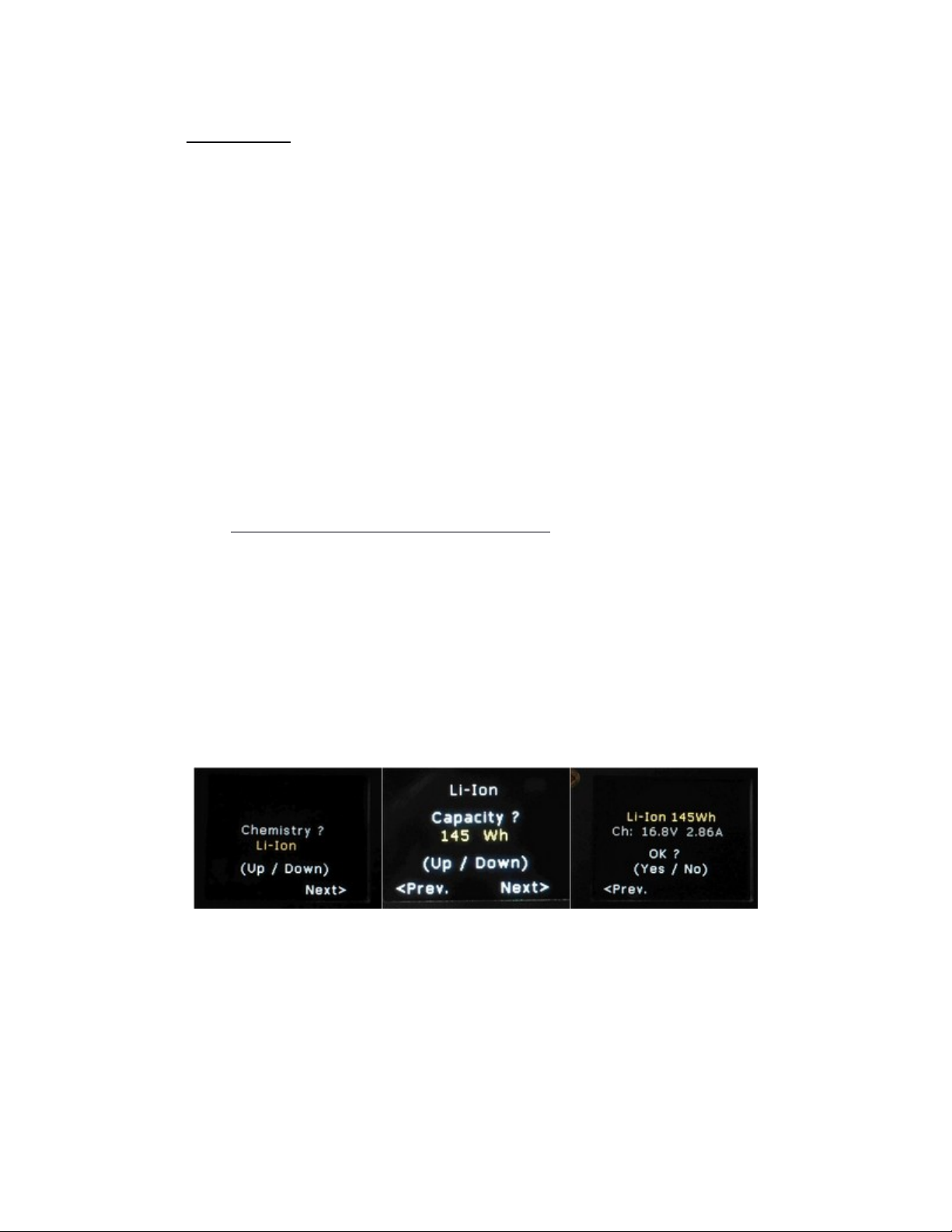
When Junior is connected to a non-Smart Battery System battery, it
asks for the battery chemistry and capacity via its color OLED screen.
A summary screen then appears, indicating charging voltage and
current. If this data is correct, the user validates it by pressing "Yes /
Enter". If it is incorrect, the user presses "Previous/Back" (<) to
correct the input parameters.
Page 3
Validated parameters are stored in non-volatile memory and held even
when Junior is turned off.
When Junior is turned back on, it checks if the battery has been
disconnected. If the same battery is still connected, the settings
are automatically reloaded from the non-volatile memory.
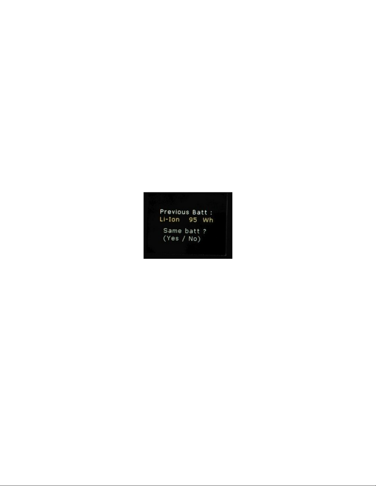
If a battery has been disconnected and then reconnected, Junior
asks "Same Batt?" to know if the newly connected battery has
the same parameters as the previous one. If the user answers
"Yes", Junior will reload the settings from the non-volatile
memory, as well as the battery’s stored state of charge before
being disconnected.
Page 4
2) SBS Battery (Smart Battery System)
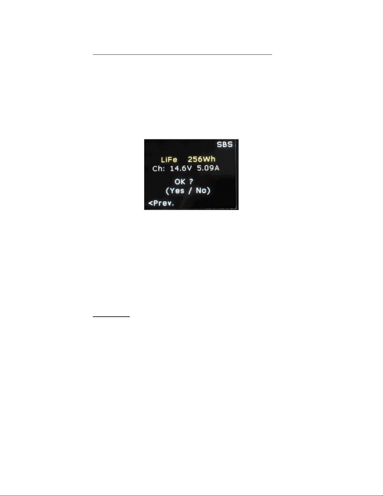
When an SBS is connected, Junior recognizes it as such, and retrieves
chemistry and nominal capacity information from the battery. This data
is displayed on the OLED screen with the related charging voltage and
current. If the chemistry data and nominal capacity are correct, the
user validates them by pressing "Yes/Enter".
If there is any inconsistency between retreived data and label on the
pack, the user can change the battery’s nominal capacity (therefore
the charging current), but not its chemistry (i.e. the charging voltage).
Once the capacity is changed, the user presses "Forward/Next" (>)
and then "Yes/Enter" to validate the corrected parameters.
3) AC Line
Junior can accept line voltage between 90 and 260 Vac, and between
48 to 63 Hz. Input is protected by a 250V/2AT fuse (5mm x 20mm
glass cartridge type). The line voltage connector is 3-pole IEC with
earth.
Page 5
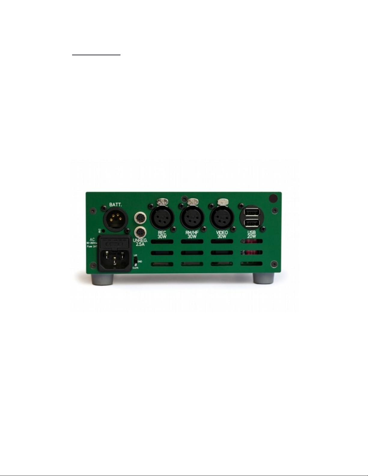
B) Outputs
Junior has six outputs on its rear panel for powering the sound gear.
Four are switched outputs, controlled by switches on the front panel.
Two are unswitched outputs that are powered when Junior is turned
on.
Page 6
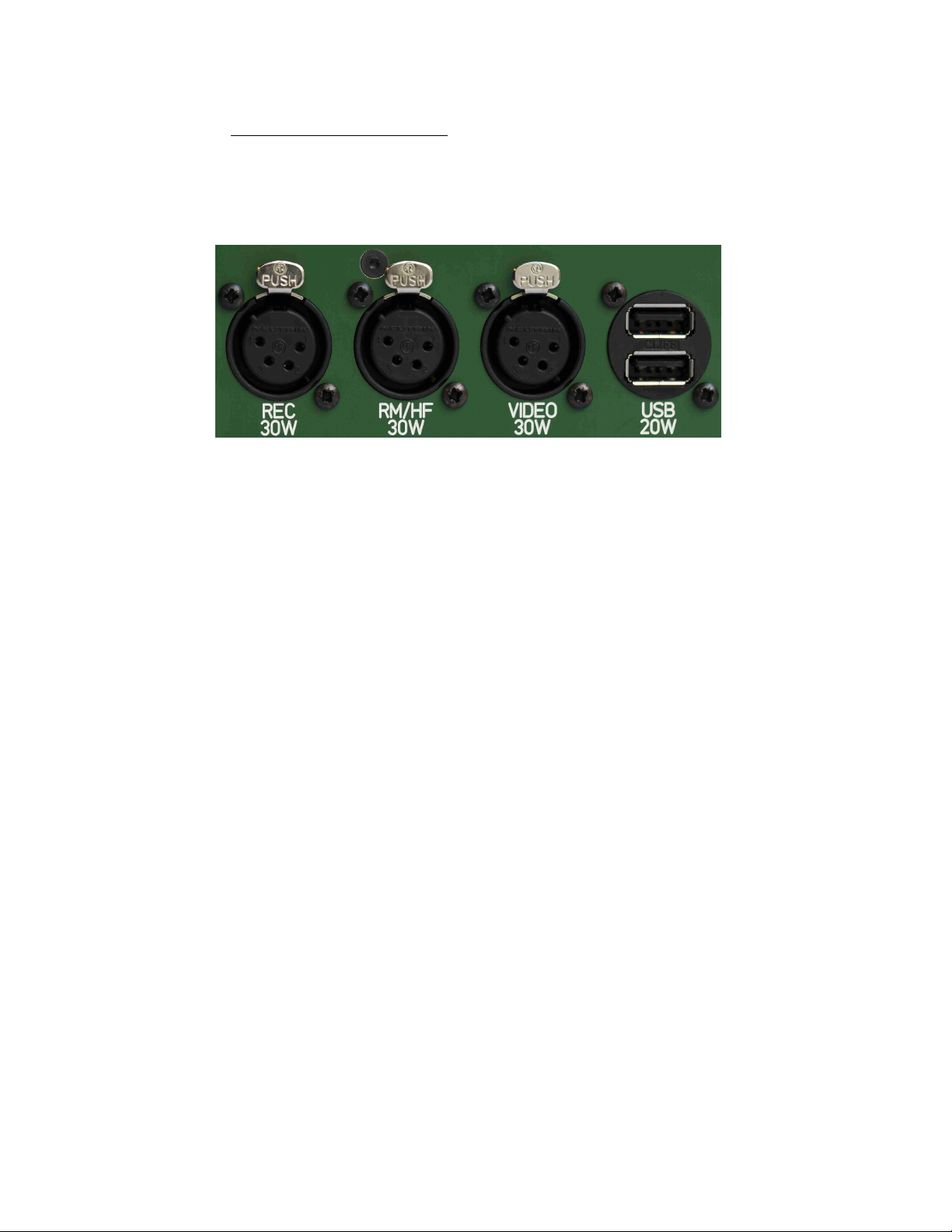
1) Switched Outputs
The four switched outputs are fitted with floating ground DC/DC
converters. From left to right, they are:
An REC output is for the recorder and its control surface.
It provides 15V, 30W i.e. 2A max. on XLR4F connector;
An RM/HF output is for the RadioMikes receivers rack, antennas
coupler and powered antennas, as well as transmitters for Radio
Monitors.
It provides 12V, 30W i.e. 2.5A max. on XLR4F connector;
A VIDEO output is for the camera monitors.
It provides 12V, 30W i.e. 2.5A max. on XLR4F connector;
USB output, for running or charging two 5V USB-A powered
devices.
It provides 5V, 20W, i.e. 4A max. on stacked ports.
The four switched outputs are controlled by illuminated toggle switches
on Junior’s front panel:
on green toggle, the respective switched output is activated at
the correct voltage.
on red toggle, the output voltage is too low for the respective
switched output. This could mean that there is a short-circuit;
the connected device is drawing too much power; or it is
overheating (converter goes in self-protection).
Page 7
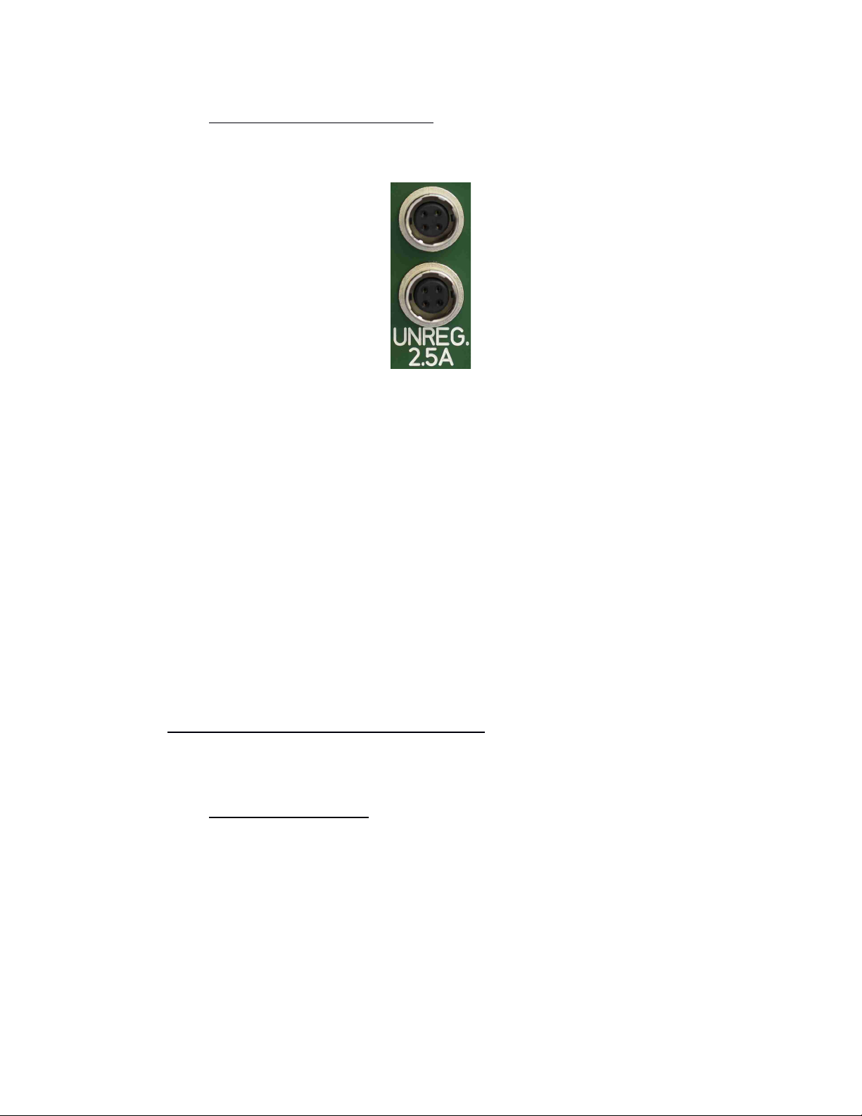
2) Unswitched Outputs
Two unswitched outputs are powered when Junior is turned on. These
allow the user to connect accessories that do not require regulation
such as lights, fans, additional USB chargers, etc.
These outputs are filtered and protected by a resettable fuse. Since
they're unregulated, the output voltage can vary between 13.7V (AC
line) and the battery voltage (ranging from 11V for a discharged SLA
battery to 16V for a fresh Li-Ion one).
Maximum total current for the two unswitched outputs is 2.5A on 4
pins HRS connectors.
C) Displays and Switches
1) On front panel
Junior’s front panel features a large 160x128 pixels OLED panel.
This panel displays three main screens, in addition to the screens
necessary for battery definition and validation. The user presses
the "No/Display" button to toggle between these screens.
Page 8
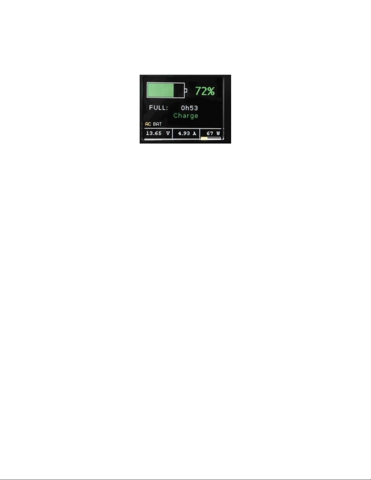
a) Main Screen:
A battery symbol showing the state of the battery’s charge, and
its percentage value;
The system status: battery discharging (in red) and time to
empty; battery charging (in green) and time to full; full battery
with no power draw (in grey);
An AC BAT indicator displays the active energy source (in
yellow);
A power meter shows the output board voltage, the total current
drawn and the resulting power consumed;
A small bar graph under the power value changes in size and
color (green, yellow or red) depending on the power source
being used and the power consumption. For example, if the
connected outputs are consuming 50W while Junior is connected
to a 49Wh Li-Ion battery, the bar graph is red and long as this is
a risky and potentially dangerous situation. If the connected
outputs are consuming 15W while Junior is connected to AC line
voltage, a short green bar graph is displayed as this is a safe
condition.
Page 9

Page 10
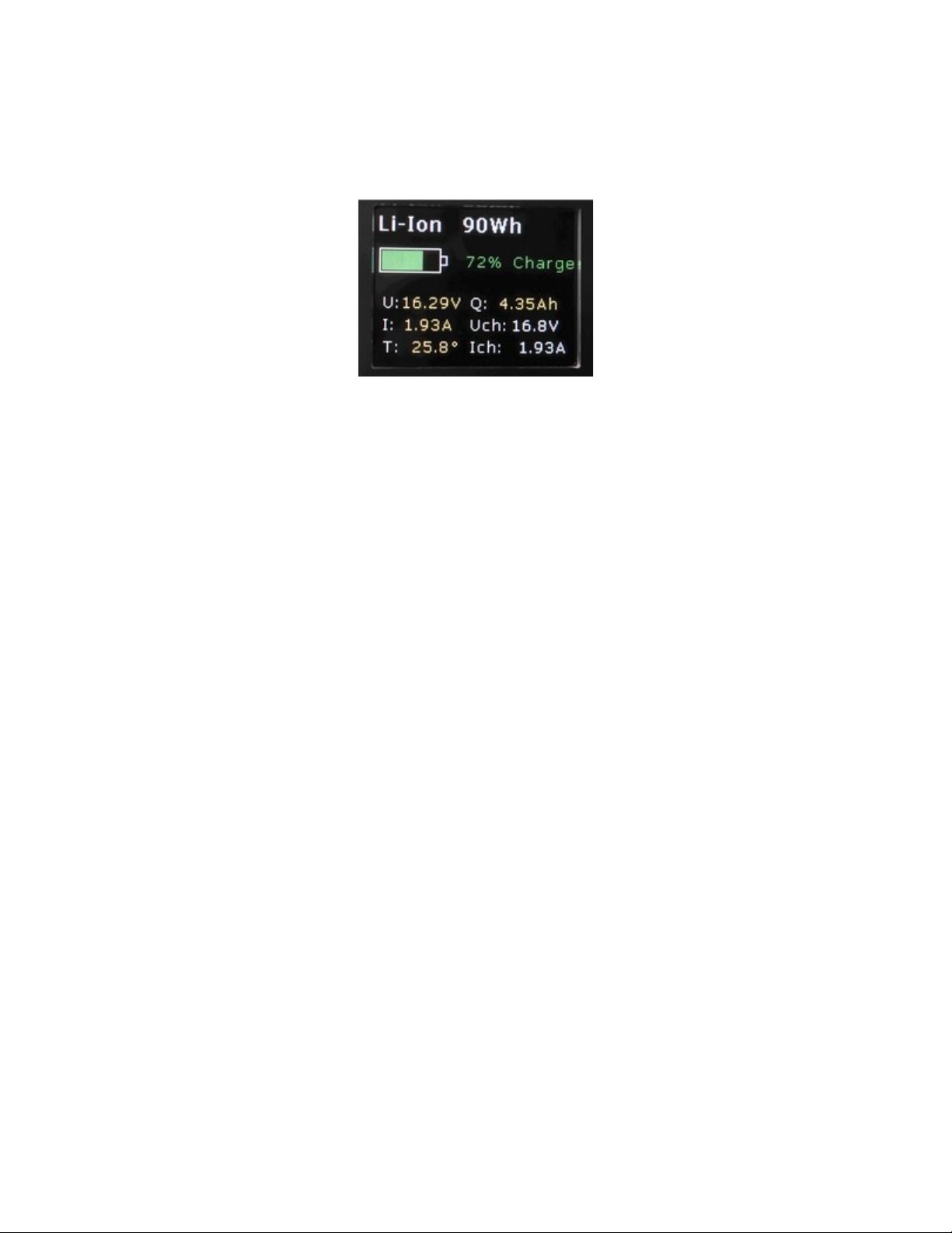
b) Battery Details Screen:
Battery chemistry and design capacity, and if an SBS battery has
been connected;
The battery’s state of charge as a percentage value, and a
battery symbol indicating its status, green for charging and red
for discharging;
The two columns below show : the battery voltage in volts, its
output (negative) or accepted (positive) current in amperes, its
temperature in degrees Celsius, and its remaining electrical
charge in Ah. These dynamic values are displayed in yellow. The
static voltage and charging current values are displayed in white.
Page 11
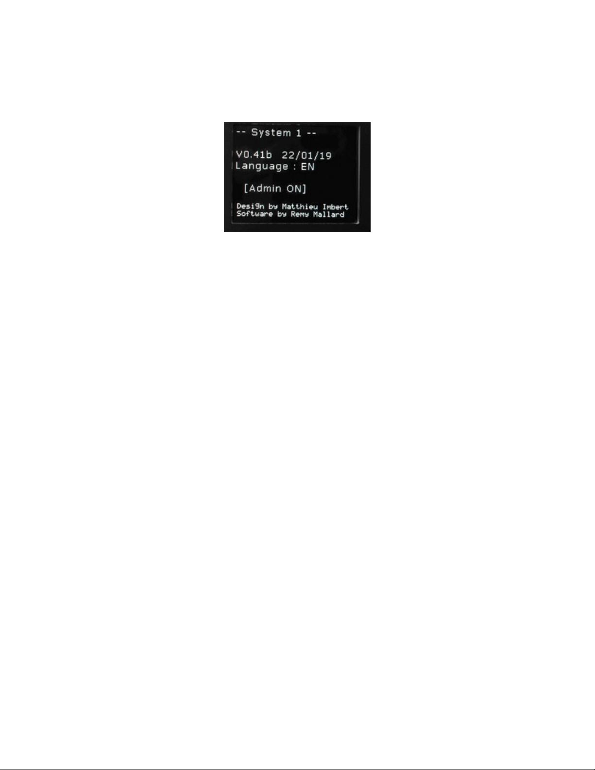
c) System Screen:
The software version and its build date (DD/MM/YY) ;
The language used ;
The system mode: [Admin OFF] or [Admin ON] ;
And the names of the great designers of this beautiful device !
Page 12
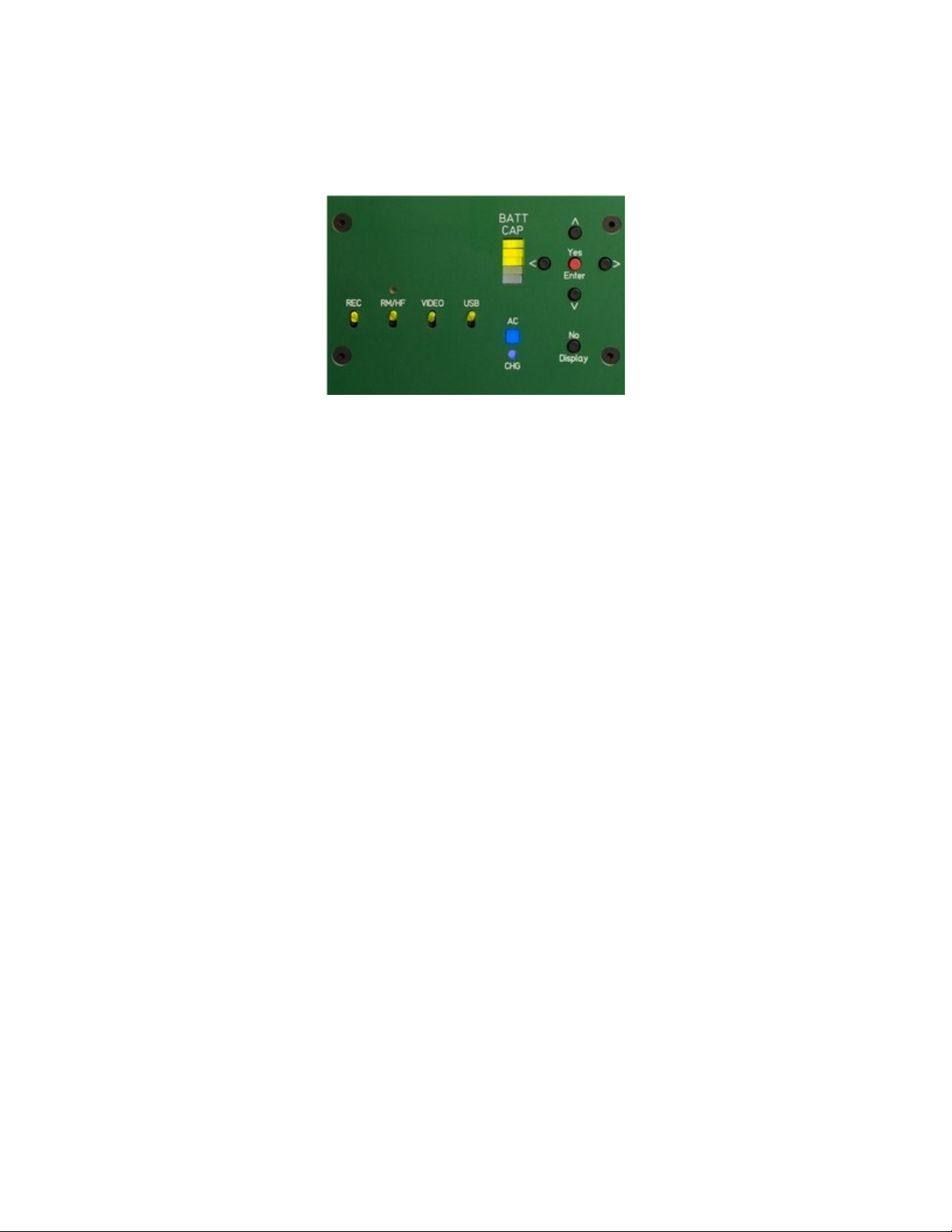
d) Front Panel LED’s:
LEDs on Junior’s front panel display:
When Junior is connected to a battery the five-LED bar graph
labeled “BATT CAP” shows the relative state of charge (RSOC) in
20% increments. When Junior is connected to AC line voltage,
the bargraph is illuminated even when Junior is turned off: the
user can monitor charging progress without turning Junior on;
The blue square LED labeled “AC” is illuminated whenever Junior
detects AC line voltage;
A red/yellow/green round LED labeled “CHG” shows the charging
status. Red indicates constant current; yellow indicates constant
voltage; and green indicates charge almost completed (for Li-Ion
or LiFe battery) or float charge (13.8V, for SLA batteries only);
The four illuminated LED toggle switches for the main outputs
are described in section B-1 “Switched Outputs”, above;
Junior’s yellow main power switch, which is not an LED, is used
to turn it on and off: press for one second to turn on, and press
for two seconds to turn off.
Page 13
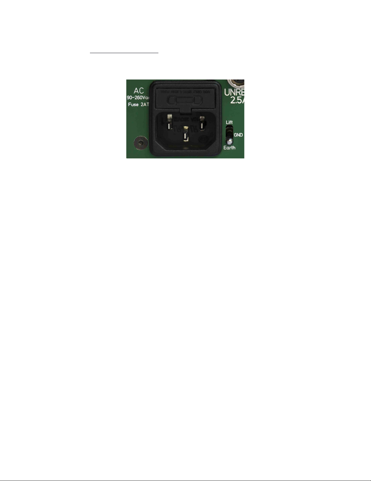
2) On Back Panel
On the back panel, a toggle switch next to the AC line voltage input
allows the user change Juniors grounding between Lift and Earth.
When the toggle is in the position marked “Earth” it connects Junior
electrical ground to earth (chassis).
When the toggle is in the position marked “Lift” it separates the earth
(chassis) from the electrical ground of Junior. This can help resolve
ground loops.
 Loading...