

Page 1

MANUALE D’USO – Sezione 1
USER MANUAL - Section 1
Le avvertenze nel presente manuale devono essere osservate congiuntamente al “MANUALE D’USO - Sezione2”.
The warnings in this manual must be observed together with the “USER MANNUAL- Section 2”.
Page 2

EMI CLASSIFICATION
EMI CLASSIFICATION
According to the standards EN 55103 this equipment is designed and suitable to operate in E5 Electromagnetic
environments.
FCC CLASS A STATEMENT ACCORDING TO TITLE 47, PART 15, SUBPART B,
§15.105
This equipment has been tested and found to comply with the limits for a Class A digital device, pursuant to part
15 of the FCC Rules.
These limits are designed to provide reasonable protection against harmful interference when the equipment is
operated in a commercial environment.
This equipment generates, uses and can radiate radio frequency energy and, if not installed and used in
accordance with the instructions, may cause harmful interference to radio communications.
Operation of this equipment in a residential area is likely to cause harmful interference in which case the user will
be required to correct the interference at his own expense.
Changes or modications not expressly approved by the party responsible for compliance could void the user’s
authority to operate the equipment.
NFC MODULE
This equipment contains a transmitter module
FCC ID:2ADDV-NFCVIO
IC:12207A-NFCVIO
VIO-S218
2
Cod. 420120267 REV. 0.1
Page 3
IMPORTANT SAFETY INSTRUCTIONS:
1. Read these instructions
2. Keep these instructions.
3. Heed all warnings.
4. Follow all instructions.
5. Do not use this apparatus near water.
6. Clean only with dry cloth.
7. Do not block any ventilation openings. Install in accordance with the manufacturer’s instructions.
8. Do not install near any heat sources such as radiators, heat registers, stoves, or other apparatus (including
ampliers) that produce heat.
9. Do not defeat the safety purpose of the polarized or grounding-type plug. A polarized plug has two blades with
one wider than the other. A grounding type plug has two blades and a third grounding prong. The wide blade or
the third prong are provided for your safety. If the provided plug does not t into your outlet, consult an electrician
for replacement of the obsolete outlet.
10. Protect the power cord from being walked on or pinched particularly at plugs, convenience receptacles, and the
point where they exit from the apparatus.
11. Only use attachments /accessories specied by the manufacturer.
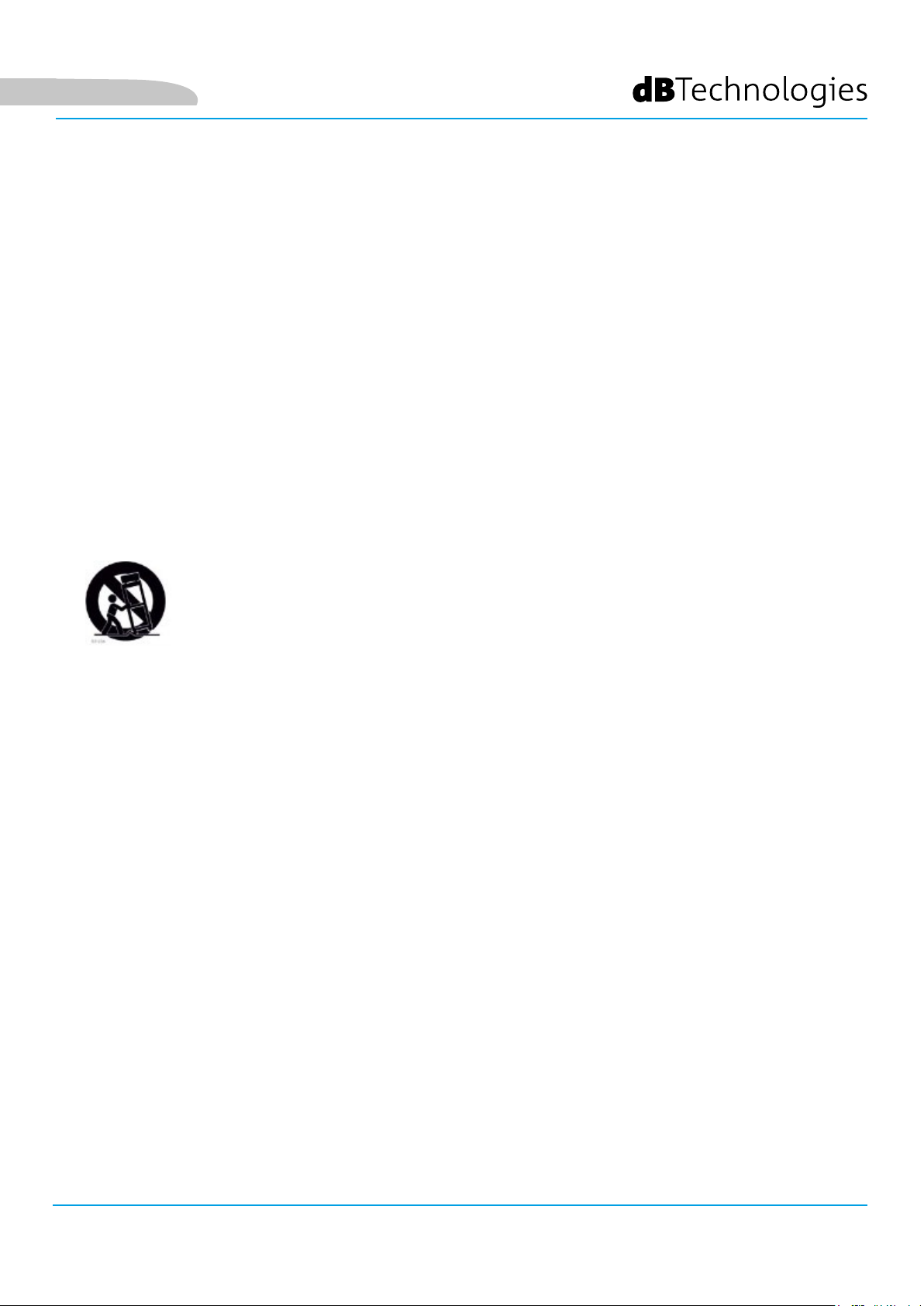
12.
the apparatus. When a cart is used, use caution, when moving the cart/apparatus combination to avoid injury from
tip-over.
13. Unplug this apparatus during lightning storms or when unused for long periods of time.
14. Refer all servicing to qualied service personnel. Servicing is required when the apparatus has been damaged
in any way, such as power-supply cord or plug is damaged, liquid has been spilled or objects have fallen into the
apparatus has been exposed to rain or moisture, does not operate normally, or has been dropped.
ADDITIONAL SAFETY INSTRUCTIONS:
• No naked ame sources, such as lighted candles, should be placed on the apparatus
• Do not use the apparatus in tropical climates
Use only with the cart, stand tripod, bracket, or table specied by the manufacturer, or sold with
VIO-S218 Cod. 420120267 REV. 0.1
3
Page 4

WARNING
Make sure that the loudspeaker is securely installed in a stable position to avoid any injuries or damages to
persons or properties. For safety reasons di not place one loudspeaker on top of another without proper fastening
systems. Before hanging the loudspeaker check all the components for damages, deformations, missing or
damaged parts that may compromise safety during installation. If you use the loudspeakers outdoor avoid spots
exposed to bad weather conditions.
Contact dBTechnologies for accessories to be used with the speakers. dBTechnologies will not accept any
responsibility for damages caused by inappropiate accessories or additional devices.
VIO-S218
4
Cod. 420120267 REV. 0.1
Page 5

ITALIANO
ENGLISH
VIO-S218 Cod. 420120267 REV. 0.1
5
Page 6
Italiano
INDICE
INDICE
1. INFORMAZIONI GENERALI ................................................................................................... 7
BENVENUTI! ........................................................................................................................ 7
PANORAMICA INTRODUTTIVA .......................................................................................... 7
RIFERIMENTI PER L’UTENTE ................................................................................................ 7
CARATTERISTICHE MECCANICHE ED ACUSTICHE ............................................................. 8
DIMENSIONI E PESO .................................................................................................................................. 8
CARATTERISTICHE ACUSTICHE .................................................................................................................. 8
MECCANICA ............................................................................................................................................... 9
ACCESSORI ............................................................................................................................................... 10
CARATTERISTICHE DELLA SEZIONE DI AMPLIFICAZIONE E DI CONTROLLO ................. 11
SEZIONE DI INPUT, OUTPUT E DI CONTROLLO ...................................................................................... 12
SEZIONE DI ALIMENTAZIONE .................................................................................................................. 14
2. DBTECHNOLOGIES COMPOSER .......................................................................................... 15
3. PARAMETRI DI CONFIGURAZIONE .................................................................................... 17
4. COLLEGAMENTI ................................................................................................................... 19
COLLEGAMENTO E RILANCIO DELL’ALIMENTAZIONE............................................................................. 19
COLLEGAMENTO E RILANCIO DEL SEGNALE AUDIO E RDNET .............................................................. 20
5. INSTALLAZIONE E CONFIGURAZIONE ............................................................................... 22
CONTENUTO DELLA CONFEZIONE .................................................................................. 22
INSTALLAZIONE IN CONFIGURAZIONI MULTIPLE ........................................................... 22
CONFIGURAZIONE CARDIOIDE ....................................................................................... 22
CONFIGURAZIONE ENDFIRE ............................................................................................ 23
INSTALLAZIONE STACKED ................................................................................................ 24
6. RISOLUZIONE DEI PROBLEMI ............................................................................................. 25
7. AGGIORNAMENTO DEL FIRMWARE .................................................................................. 26
8. SPECIFICHE TECNICHE ......................................................................................................... 27
GENERALE ................................................................................................................................................ 27
DATI ACUSTICI .......................................................................................................................................... 27
AMPLIFICATORE ....................................................................................................................................... 27
PROCESSORE ............................................................................................................................................ 27
INTERFACCIA UTENTE .............................................................................................................................. 28
INGRESSI ED USCITE ................................................................................................................................ 28
SPECIFICHE DI ALIMENTAZIONE (ASSORBIMENTO) ............................................................................... 28
SPECIFICHE MECCANICHE ....................................................................................................................... 29
VIO-S218
6
Cod. 420120267 REV. 0.1
Page 7

Italiano
1. INFORMAZIONI GENERALI
BENVENUTI!
Grazie per aver acquistato un prodotto progettato e sviluppato in Italia da dBTechnologies! Questo subwoofer è
frutto di una lunga esperienza nel campo della diffusione sonora. Impiega soluzioni ottimizzate in campo acustico
ed elettronico, oltre che nella scelta dei materiali.
PANORAMICA INTRODUTTIVA
La famiglia VIO prosegue la nuova stagione dBTechnologies nel campo della diffusione sonora per le applicazioni
live indoor e outdoor di medie e grandi dimensioni.
VIO-S218 è un subwoofer attivo professionale, che, nell’utilizzo con i line-array array VIO, permette di ottenere un
sistema completo, dalle prestazioni acustiche ottime su un range di frequenze esteso.
Le sue caratteristiche principali sono:
• 2 woofer da 18” (voice coil: 4”)
• 2 amplicatori in classe D (2 x 1600 W RMS)
• predisposizioni integrate che garantiscono congurabilità ed ergonomicità nell’utilizzo con altri
VIO-S218
• cabinet di alta qualità in legno multistrato, con nitura in poliurea che aumenta la durevolezza
superciale
• tecnologia Floating ADC, sviluppata per un perfetto isolamento da interferenze, rumori o ronzii,
dell’ingresso audio
• rilanci di alimentazione, audio e di rete per un cablaggio ottimizzato
• controllo RDNet on-board e software predittivi e di gestione remota (DBTECHNOLOGIES COMPOSER,
EASE, EASE FOCUS 3, AURORA NET)
• accessori dedicati (carrello DO-VIOS218) per la movimentazione in sicurezza
RIFERIMENTI PER L’UTENTE
Per utilizzare al meglio il vostro diffusore VIO consigliamo di:
• leggere il manuale d’uso quick start presente nella confezione e questo manuale d’uso completo in
ogni sua parte e conservarlo per tutta la durata di vita del prodotto.
• registrare il prodotto sul sito http://www.dbtechnologies.com nella sezione “SUPPORTO”.
• conservare prova d’acquisto e GARANZIA (Manuale d’uso “sezione 2”).
VIO-S218 Cod. 420120267 REV. 0.1
7
Page 8

CARATTERISTICHE MECCANICHE ED ACUSTICHE
DIMENSIONI E PESO
Il cabinet in legno, rivestito in poliurea, pesa 85,6 kg (188,72 lbs).
Le misure sono: 1300 mm (L), 520 mm (A), 800 mm (P).
Italiano
CARATTERISTICHE ACUSTICHE
La progettazione acustica di VIO S218 coniuga un’ampia superficie di radiazione con dimensioni compatte per
un subwoofer di questa fascia di utilizzo. Grazie ai controlli gestiti da DSP, la direttività in configurazione di
utilizzo multipla ne rende versatile l’utilizzo.
VIO-S218
Cod. 420120267 REV. 0.1
8
Page 9

Italiano
MECCANICA
A
1
3
2
4
B
7
6
5
8
C
9
10
L’ergonomia del subwoofer ed il rapido montaggio in congurazione multipla sono garantiti da:
LATI [vista A]
1) Maniglie verticali (2 per lato). Facilitano il sollevamento quando il subwoofer è in posizione orizzontale.
2) Maniglie orizzontali (2 per lato). Facilitano la movimentazione, ad esempio se si vuole ruotare il subwoofer.
3) Punti integrati per il ssaggio con cinghie (2 per lato).
4) Piedini plastici (4 su un lato) per utilizzo in congurazione verticale (per questo utilizzo è necessario un ssaggio
addizionale, non incluso).
11
LATO SUPERIORE [vista B]
5) Scanalature passacavi. Permettono di far passare i cavi tra i subwoofer per un cablaggio ordinato e
semplice in congurazione cardioide.
6) Fori per il montaggio del y-bar DRK-212/DRK-210.
7) Sedi di appoggio per piedi inferiori [8]. Permettono il posizionamento stabile di più VIO-S218 sovrapposti.
RETRO E LATO INFERIORE [vista C]
8) Rain cover. Protegge l’amplicatore dall’acqua, permettendo di operare anche in condizioni meteo critiche. Per
semplicità non sarà mostrato successivamente nel presente manuale.
9) Predisposizioni per ruote (4 in totale). Per il montaggio del kit SWK-18 (vedi la sezione ACCESSORI).
10)Scanalature passacavi (2 sul lato inferiore). Permettono di far passare i cavi sotto al subwoofer per un cablaggio
ordinato e semplice in congurazione cardioide.
11)Piedi inferiori (4 in totale). Stabilizzano l’appoggio e, inseriti nelle sedi [11], la costruzione di congurazioni a
subwoofer sovrapposti.
VIO-S218 Cod. 420120267 REV. 0.1
9
Page 10

ACCESSORI
Per un rapido montaggio, sono previsti come opzionali i seguenti accessori:
• DRK-212, y-bar per l’utilizzo in stacked dei line array di moduli VIO-L212.
• DRK-210, y-bar per l’utilizzo in stacked dei line array di moduli VIO-L210.
• DO-VIOS218/S318, carrello per il trasporto dei subwoofer VIO S218. E’ adatto all’utilizzo di un carrello
elevatore.
• SWK-18 kit, 4 ruote montabili sul retro del subwoofer (posizione [9], vedi la sezione MECCANICA).
Italiano
DO-VIOS318DRK-212
DRK-210
ATTENZIONE!
• Utilizzare solo gli accessori e le congurazioni indicate nel presente manuale e operare in accordo
a quanto indicato nei manuali relativi agli accessori.
• La movimentazione con carrello DO-VIOS218 implica l’utilizzo tassativo di cinghie di sicurezza (non
fornite).
• DRK-210, sul top di un SUB S218 permette di posizionare al massimo 3 moduli VIO L210 in
congurazione stacked. Ogni dettaglio installativo deve essere vericato con il software gratuito
dBTechnologies COMPOSER, disponibile sul sito
www.dbtechnologies.com.
Per ogni ulteriore informazione si prega di consultare i manuali relativi.
Per tutti gli aggiornamenti sugli accessori consultare il sito www.dbtechnologies.com
VIO-S218
10
Cod. 420120267 REV. 0.1
Page 11
Italiano
CARATTERISTICHE DELLA SEZIONE DI AMPLIFICAZIONE E DI CONTROLLO
I 2 amplicatori in classe D sono il cuore dei subwoofer VIO-S218.
Permettono di erogare no a 1600 W RMS per sezione, quindi in totale si ottengono no a 3200 W RMS. Il
funzionamento è silenzioso ed efciente.
Il controllo del sistema è afdato a un potente DSP che rende possibile la congurazione immediata e semplice
in qualsiasi contesto di utilizzo. Grazie alla possibilità di collegamento in rete con RDNet, i parametri sul pannello
possono essere controllati in remoto, grazie al software “AURORA NET” (vedere il paragrafo PARAMETRI DI
CONFIGURAZIONE).
SEZIONE DI
CONTROLLO
INGRESSO, USCITA E
SEZIONE DI
ALIMENTAZIONE
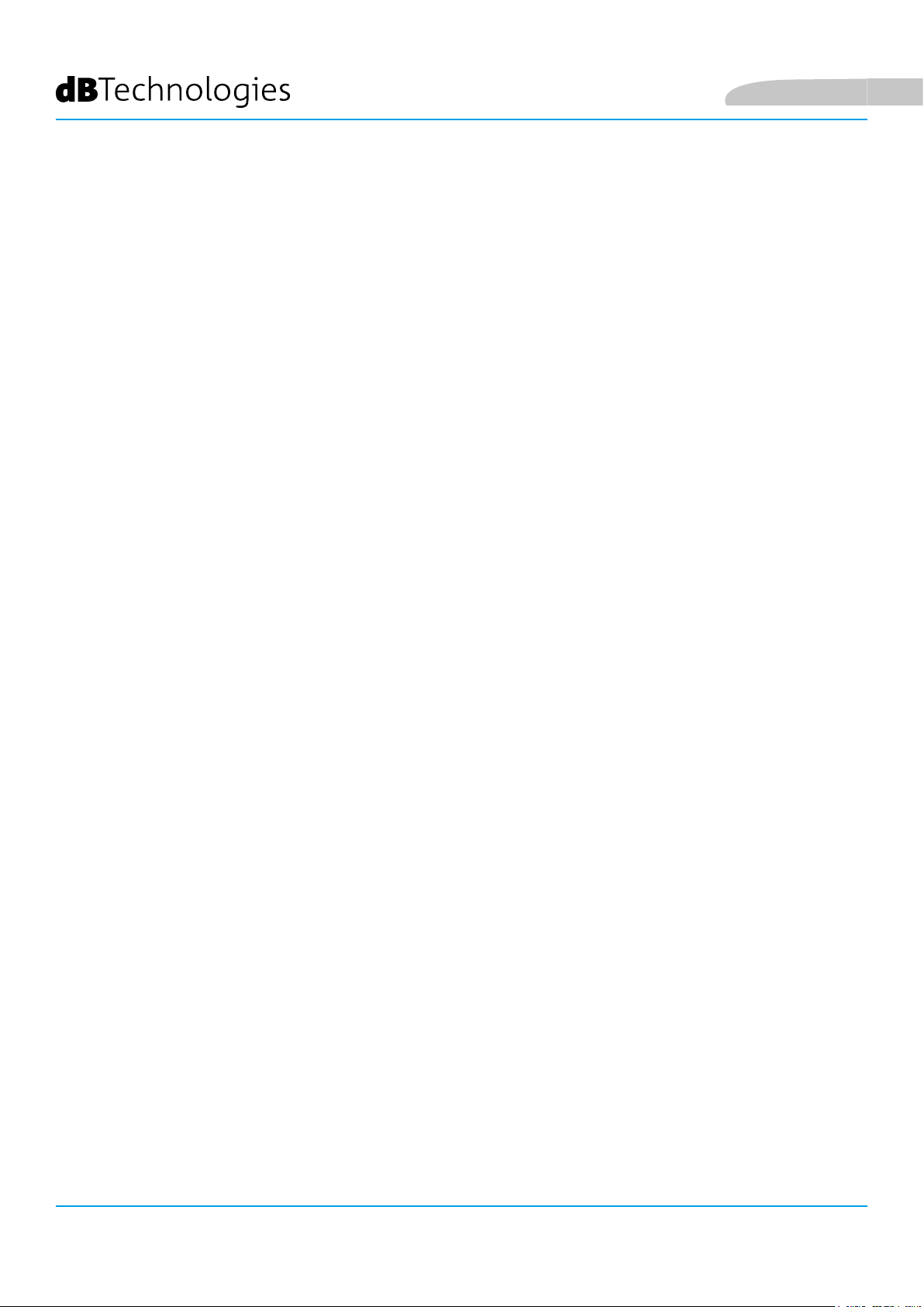
Il pannello posto sul retro del subwoofer è caratterizzato da:
• Sezione di Input, Output e Controllo
• Sezione di Alimentazione
VIO-S218 Cod. 420120267 REV. 0.1
11
Page 12

SEZIONE DI INPUT, OUTPUT E DI CONTROLLO
5 6 7 4 3
Italiano
1
1. INGRESSO AUDIO (“Balanced audio Input”)
Ingresso compatibile con cavi XLR blanciati. Si utilizza per il collegamento in ingresso del segnale audio
proveniente dal mixer, o da un altro speaker o subwoofer in congurazione daisy chain.
2
9
8
Italiano
2. RILANCIO AUDIO (“Balanced audio Link”)
Uscita compatibile con cavi XLR blanciati. Si utilizza per il rilancio del segnale audio agli altri VIO S218 in
congurazione daisy-chain.
3. ATTENUAZIONE DEL SEGNALE AUDIO (“Subwoofer Attenuation)
Permette di regolare l’attenuazione del subwoofer.
Porre a 0 dB prima di iniziare a congurare il subwoofer ed il sistema.
4. LED DI STATO (“Status”)
Led relativi al funzionamento del modulo. Una tabella nella pagina seguente riepiloga e sintetizza il signicato
dei vari LED.
5. SELETTORE DI POLARITA’ (“Polarity”)
Permette di invertire la polarità del subwoofer. Può essere utile per allineare la fase tra vari subwoofer o fra un
subwoofer e i moduli line-array. Vedere per ogni ulteriore dettaglio il capitolo PARAMETRI DI CONFIGURAZIONE.
6. CONTROLLO DI DELAY (“Delay” [ms])
I due selettori rotativi permettono di impostare il ritardo del segnale in uscita nel range 0-9.9 ms. Un selettore
regola il valore intero del ritardo, il secondo quello decimale.
7. SELETTORE MODALITA’ CARDIOIDE (“Cardioid preset”)
Permette di congurare l’utilizzo cardioide con un solo comando. In caso sia selezionata questa modalità, il led
“Active” è acceso ed i valori di polarità e ritardo risultano by-passati.
8. USCITA AUDIO CON FILTRO PASSA-ALTO (“HPF Xover output”)
Uscita compatibile con cavi XLR blanciati. Nel caso l’uscita audio del subwoofer sia inviata direttamente ad un
sistema VIO-L210, è possibile utilizzare un segnale audio ltrato alla frequenza di Xover. Questa frequenza è
selezionata con l’apposito controllo XOVER [9].
9. SELETTORE DI FREQUENZA XOVER (“Xover [Hz]”)
Seleziona la frequenza XOVER (70-75-80-85-90-95-95-100-105-Fullrange)applicata all’uscita [8]. La posizione Service/
User va invece utilizzata per lo stato di aggiornamento del rmware o per richiamare un’impostazione USER (vedi
il manuale di DBTECHNOLOGIES NETWORK). Vedi anche la sezione AGGIORNAMENTO DEL FIRMWARE
e la sezione
VIO-S218
Cod. 420120267 REV. 0.1
12
Page 13

Italiano
TIPO LED FASE DI ACCENSIONE
DELLO SPEAKER
IN FUNZIONE
NORMALE
WARNING
GENERICO
BLOCCO PER
ANOMALIA DELLO
SPEAKER
LIMITER SPENTO SPENTO, SI
ACCENDE SOLO
IN CASO DI
INTERVENTO
SIGNAL
MUTE/
PROT
READY SPENTO ACCESO FISSO ACCESO FISSO SPENTO
SPENTO LAMPEGGIO
ACCESO PER QUALCHE
SECONDO
Tabella di segnalazione dei LED di stato
IN PRESENZA DI
SEGNALE
SPENTO LAMPEGGIO
LAMPEGGIO
MOMENTANEO
SEGNALAZIONE
NORMALE DI
AUDIO IN
INGRESSO
MOMENTANEO
LAMPEGGIO CICLICO
CONTINUO
SPENTO
ACCESSO FISSO
10 1112
10. INGRESSO DELLA CONNESSIONE DI RETE RDNet (“Data In”)
Per cavi di rete dotati di connettori di tipo etherCON/RJ45.
Collegarlo a dispositivi come RDNet Control 2 o Control 8 per utilizzare il controllo remoto.
11. RILANCIO DELLA CONNESSIONE DI RETE RDNet (“Data Out”)
Compatibile con cavi di rete dotati di connettori di tipo etherCON/RJ45.
Viene utilizzato per il rilancio della rete di controllo remoto ad ulteriori moduli del sistema in congurazione
daisy-chain.
12. LED DI CONTROLLO
Led relativi al funzionamento in rete (RDNet) del modulo.
In particolare, “Link” acceso segnala che la rete RDNet è attiva e ha riconosciuto il dispositivo, “Active” in modalità
lampeggiante che esiste trafco dati, “Remote Preset Active” che tutti i controlli locali sul pannello amplicatore
sono by-passati dal controllo remoto RDNet.
13. USB DATA SERVICE
Porta di tipo mini-USB B, da utilizzare esclusivamente per l’aggiornamento del rmware del prodotto. Vedi la
sezione “AGGIORNAMENTO DEL FIRMWARE” per ulteriori informazioni.
14. SYSTEM TEST
Effettua un test con segnale sweep per vericare l’integrità del
woofer. Questo test non va considerato esaustivo, ma solo un primo controllo nell’analisi di eventuali
problematiche
13
14
VIO-S218 Cod. 420120267 REV. 0.1
13
Page 14
SEZIONE DI ALIMENTAZIONE
Italiano
15 16
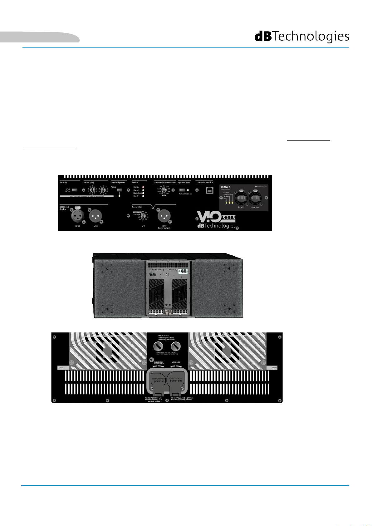
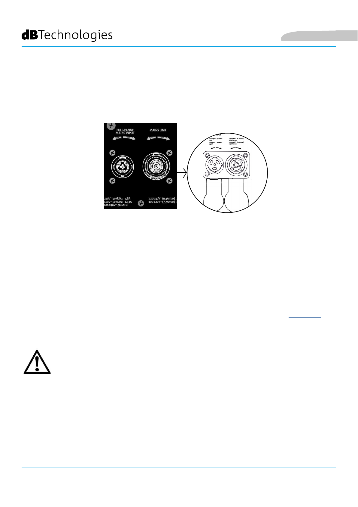
15. CONNETTORE DI ALIMENTAZIONE “MAINS INPUT”
Compatibile con connettore powerCON TRUE1®, l’alimentazione è dotata di funzione autorange. La tensione
di utilizzo è riconosciuta automaticamente (intervalli: 100-120V~ oppure 220-240V~). Dotato di protezione di
chiusura in gomma (mostrata in gura). Per semplicità questa protezione non sarà mostrata successivamente nel
manuale.
16. RILANCIO DI ALIMENTAZIONE “MAINS LINK”
Compatibile con connettore tipo powerCON TRUE1® per il rilancio dell’alimentazione ad altri moduli.
Dotato di protezione di chiusura in gomma (mostrata in gura). Per semplicità questa protezione non sarà
mostrata successivamente nel manuale. Per il numero massimo di elementi in un sistema rilanciato confrontare la
sezione SPECIFICHE TECNICHE.
ATTENZIONE!
• I connettori di questa sezione svolgono anche la funzione di interruttori di alimentazione.
• Non ostruire le alette posteriori di raffreddamento dell’amplicatore. In caso di
surriscaldamento eccessivo, il volume audio viene ridotto gradualmente no alla
stabilizzazione termica del modulo. Il livello viene ristabilito automaticamente al
raggiungimento della corretta temperatura di funzionamento.
• In caso di malfunzionamento, interrompere immediatamente l’alimentazione, e
scollegare il modulo dalla rete. Rivolgersi ad un riparatore autorizzato.
• Non tentare in nessun modo di aprire l’amplicatore.
• Utilizzare solo cavi dotati di connettori originali Neutrik®, di alta qualità. Controllarne
periodicamente l’integrità.
VIO-S218
14
Cod. 420120267 REV. 0.1
Page 15
Italiano
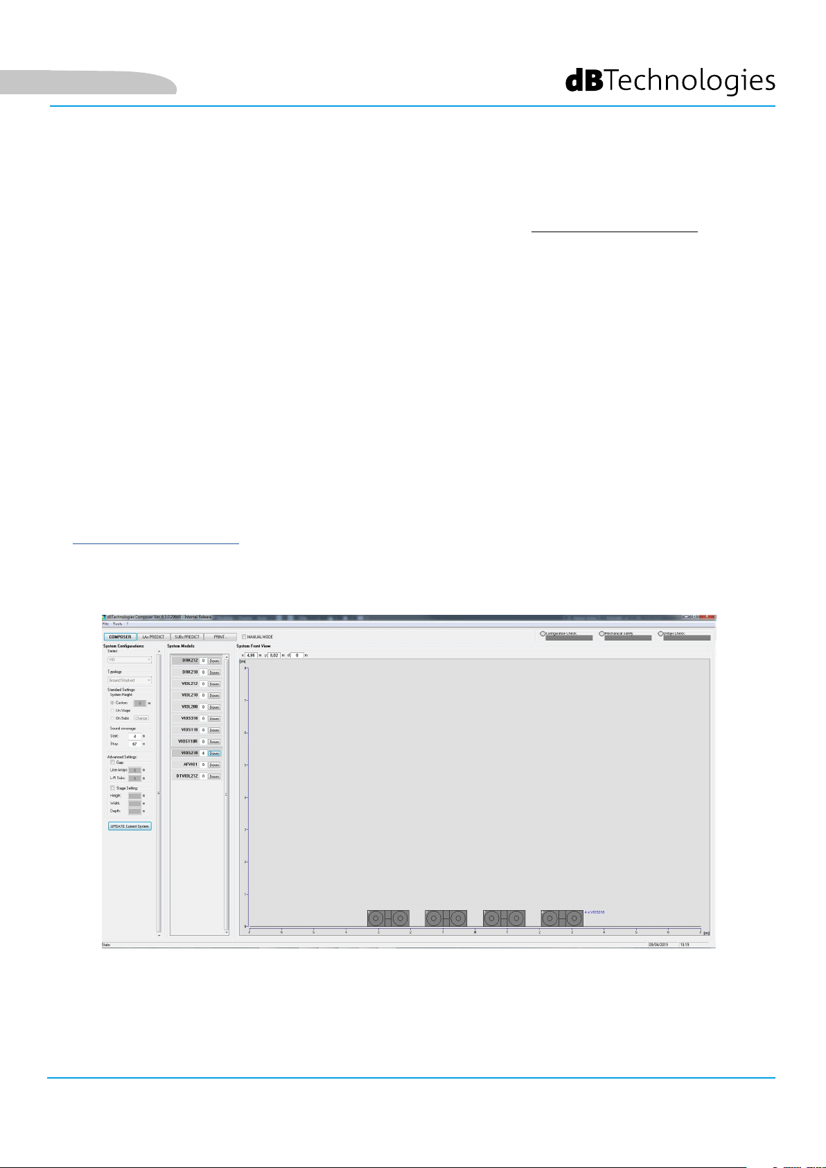
2. DBTECHNOLOGIES COMPOSER
Il software dBTechnologies Composer, scaricabile gratuitamente dal sito www.dbtechnologies.com, è lo
strumento per la corretta progettazione di sistemi audio consigliato per tutta la serie VIO.
Suggerisce la soluzione per gli spazi da sonorizzare, indicando il corretto posizionamento dei subwoofer
VIO-S218 (e dei line -array VIO L212) per ottenere la copertura desiderata, la congurazione ed il preset da
utilizzare.
Pur essendo uno strumento predittivo, permette comunque una serie di regolazioni manuali per
perfezionare la congurazione in base ad eventuali misure audio effettuate sul campo, o a speciche
esigenze.
E’ inne lo strumento efcace per valutare la sicurezza dell’installazione.
Le sezioni principali di dBTechnologies Composer sono:
• COMPOSER - vista generale che permette l’inserimento dei dati iniziali di progetto
• LAs PREDICT - con la simulazione, congurazione e verica di sicurezza dei line-array
• SUBs PREDICT - con la simulazione, congurazione e verica di sicurezza dei subwoofer
In questo capitolo vengono evidenziati alcuni dettagli del software relativi ai subwoofer VIO-S218. Per
ogni ulteriore informazione utilizzare il manuale relativo al software, gratuitamente scaricabile sul sito
www.dbtechnologies.com
VIO-S218 Cod. 420120267 REV. 0.1
15
Page 16

Italiano
Per ottenere una simulazione predittiva, occorre inserire nella sezione COMPOSER tutti i parametri
generali di progetto del sistema.
Nella sottopagina SUBs PREDICT, vengono suggeriti: l’angolazione dei vari moduli e i vari parametri relativi
alla sezione di controllo (come delay, polarità, frequenza di crossover). Inoltre un messaggio relativo alla
messa in sicurezza dell’installazione compare nel riquadro “Mechanical Safety”.
Utilizzare queste informazioni congurare i parametri di controllo sul pannello dei subwoofer.
VIO-S218
16
Cod. 420120267 REV. 0.1
Page 17

Italiano
3. PARAMETRI DI CONFIGURAZIONE
I parametri principali di VIO S218 vengono utilizzati per ottimizzare una congurazione multipla
(es. cardioide, endre).
POLARITY - Inverte la polarità
DELAY - Imposta il valore di ritardo in [ms]
Esempio di congurazione endifre
CARDIOID PRESET - Questo parametro può essere
applicato in una congurazione come quella in
gura (cardioide a 3 elementi).
Va attivato solo sul subwoofer centrale,
meccanicamente ruotato (indicato dalla freccia).
Quando attivo, imposta automaticamente i valori
di Delay e Polarity (i cui controlli quindi sono by-
passati).
Esempio di congurazione cardioide a 3 elementi
VIO-S218 Cod. 420120267 REV. 0.1
17
Page 18

• Una volta che i vari parametri sono stati calcolati
con DBTECHNOLOGIES COMPOSER, riportarne
i valori sui controlli presenti sul pannello
amplicatore.
• Se si effettua un controllo remoto tramite
connessioni RDNet è possibile controllare tutti
i parametri del subwoofer tramite il software
gratuito AURORA NET. E’ possibile scaricarlo
nella sezione DOWNLOADS del sito www.
dbtechnologies.com. Per ulteriori informazioni si
rimanda al manuale completo di questo software.
• E’ buona norma che anche in caso di controllo
remoto, i valori iniziali di progetto calcolati con
DBTECHNOLOGIES COMPOSER siano replicati
sul pannello amplicatore di VIO S218 prima di
procedere all’installazione denitiva.
Italiano
ATTENZIONE!
• Se i parametri di controllo sono
remotati con RDNet, i parametri locali
sui pannelli dei subwoofer non sono
attivi.
Le ultime impostazioni scelte e salvate su VIO S218
possono essere successivamente richiamate sul subwoofer in assenza di controllo remoto
RDNet. E’ sufficiente ruotare il rotary Xover sulla posizione Service/User.
(con l’utilizzo di AURORA NET),
VIO-S218
18
Cod. 420120267 REV. 0.1
Page 19

Italiano
4. COLLEGAMENTI
COLLEGAMENTO E RILANCIO DELL’ALIMENTAZIONE
SUBWOOFER 2
SUBWOOFER 1
Nell’illustrazione sopra è mostrato un generico caso di collegamento in cui un subwoofer 1
è sotto al subwoofer 2. Utilizzare allo scopo cavi con connettori powerCON TRUE1® (è fornito un solo
cavo in dotazione per l’alimentazione a confezione).
• Collegare l’alimentazione del subwoofer 1 AUTO-RANGE MAINS INPUT (A).
• Rilanciare l’alimentazione dal subwoofer 1 al subwoofer 2, collegando l’uscita MAINS LINK (B)
del subwoofer 1 all’ingresso AUTO-RANGE MAINS INPUT (C) del subwoofer 2 (cavo link non fornito).
• Ripetere quest’ultima operazione no a collegare il numero massimo ammesso di subwoofer
(vedere il capitolo SPECIFICHE TECNICHE).
ATTENZIONE!
• I cavi devono essere opportunamente dimensionati e la progettazione,
installazione e verica dell’impianto devono essere effettuate esclusivamente
da personale qualicato. AEB industriale declina ogni responsabilità in caso
di utilizzo di cavi non idonei, non certicati e non compatibili col corretto
dimensionamento dell’impianto e le normative in vigore per il Paese di utilizzo.
VIO-S218 Cod. 420120267 REV. 0.1
19
Page 20

COLLEGAMENTO E RILANCIO DEL SEGNALE AUDIO E RDNET
SUBWOOFER 2
Italiano
SUBWOOFER 1
Nell’illustrazione sopra è mostrato un generico caso di collegamento in cui un subwoofer 1
è sotto al subwoofer 2, questa volta illustrando i collegamenti audio e di rete. Utilizzare allo scopo
cavi non forniti, con connettori XLR (audio) e etherCON/RJ45 (rete). Per ulteriori informazioni sui tipi
di cavi disponibili confrontare anche l’immagine nella pagina seguente.
• Per la connessione audio, collegare il cavo proveniente da MIXER/LINE all’ingresso BALANCED
AUDIO INPUT (A) del subwoofer 1. Rilanciare il segnale tra il primo e il secondo. A questo scopo
collegare l’uscita BALANCED AUDIO OUTPUT/LINK (B) del subwoofer 1 all’ingresso BALANCED
AUDIO INPUT (C) del subwoofer 2.
• Ripetere l’operazione no al collegamento del sistema completo.
• Per la connessione di rete, collegare il connettore DATA IN (A) del subwoofer 1 al controller
remoto (RDNet CONTROL 2 oppure RDNet CONTROL 8). Rilanciare il segnale collegando DATA
OUT (B) del subwoofer 1 a DATA IN (C) del subwoofer 2.
• Ripetere l’operazione no al collegamento del sistema completo.
VIO-S218
20
ATTENZIONE!
• Sostituire i cavi eventualmente danneggiati, per evitare malfunzionamenti ed
una scarsa qualità del suono (o la trasmissione dati in caso di collegamento
RDNet).
Cod. 420120267 REV. 0.1
Page 21

Italiano
VIO-S218 Cod. 420120267 REV. 0.1
21
Page 22

5. INSTALLAZIONE E CONFIGURAZIONE
CONTENUTO DELLA CONFEZIONE
Vericate che il contenuto dell’imballo del modulo VIO-S218 sia completo. L’imballo contiene:
• Subwoofer VIO-S218
• cavo powerCON TRUE1®
• quick start e documentazione relativa alla garanzia
ATTENZIONE!
Il prodotto e gli accessori devono essere utilizzati solo da personale esperto! Assicurarsi che l’installazione
sia posizionata in modo stabile e sicuro per scongiurare ogni condizione di pericolo per persone, animali e/o
cose.
L’utilizzatore è tenuto a seguire le regolamentazioni e le leggi cogenti in materia di sicurezza nel Paese in
cui si utilizza il prodotto. Per l’utilizzo in sicurezza, vericare periodicamente la funzionalità di tutte le parti
e l’integrità prima dell’utilizzo.
La progettazione, i calcoli, l’installazione, il collaudo e la manutenzione di sistemi sospesi o stack audio
professionali deve essere effettuata esclusivamente da personale autorizzato. AEB Industriale non è
responsabile per installazioni improprie, effettuate in assenza dei requisiti di sicurezza.
Italiano
INSTALLAZIONE IN CONFIGURAZIONI MULTIPLE
ATTENZIONE!
La movimentazione con carrello DO-VIOS218 implica l’utilizzo tassativo di cinghie di sicurezza.
E’ vietato l’utilizzo delle maniglie per scopi impropri come l’appendimento. E’ inoltre vietato salire sopra al
subwoofer stesso.
La corretta e sicura installazione per ogni congurazione non presentata in questa sezione deve essere opportunamenta analizzata con DBTECHNOLOGIES COMPOSER.
Effettuare l’installazione su una supercie piana, in caso contrario è necessario adottare opportuni mezzi di
ssaggio addizionale per evitare ogni pericolo di caduta o ribaltamento.
CONFIGURAZIONE CARDIOIDE
• E’ possibile montare al massimo 3 subwoofer sovrapposti in
congurazione cardioide verticale.
• Utilizzare DBTECHNOLOGIES COMPOSER per impostare i
parametri di progetto.
• Vericare che i parametri locali dei vari moduli siano impostati
correttamente sui singoli pannelli amplicatori. Effettuare
i collegamenti di rilancio audio, RDNet e di alimentazione
come descritto nei paragra precedenti. In fase di accensione,
prestare attenzione alla corrente di inrush riportata nelle
SPECIFICHE TECNICHE (es. dimensionamento elettrico di
impianto, opportunità di accensioni differite dei singoli sub).
• In caso di controllo remoto con RDNet e DBTECHNOLOGIES
NETWORK le impostazioni locali vengono by-passate ed il
controllo passa al software.
VIO-S218
22
Cod. 420120267 REV. 0.1
Page 23

Italiano
CONFIGURAZIONE ENDFIRE
• Utilizzare DBTECHNOLOGIES COMPOSER per impostare i parametri di progetto.
• Vericare che i parametri locali dei vari moduli siano impostati correttamente sui
singoli pannelli amplicatori. Effettuare i collegamenti di rilancio audio, RDNet e
di alimentazione come descritto nei paragra precedenti. In fase di accensione,
prestare attenzione alla corrente di inrush riportata nelle SPECIFICHE TECNICHE
(es. dimensionamento elettrico di impianto, opportunità di accensioni differite dei
singoli sub).
• In caso di controllo remoto con RDNet e AURORA NET le impostazioni locali
vengono by-passate ed il controllo passa al software.
VIO-S218 Cod. 420120267 REV. 0.1
23
Page 24

INSTALLAZIONE STACKED
• Per ragioni di sicurezza, è possibile montare al massimo 3 moduli in congurazione
stacked su y-bar DRK-212.
• Utilizzare DBTECHNOLOGIES COMPOSER per impostare i parametri di progetto.
• Porre su SUB 218 (installato su un piano privo di inclinazione) il y-bar DRK-212. Per i
dettagli relativi a questo accessorio vericare ulteriori dettagli sul manuale completo.
• Aggiungere ad uno ad uno i moduli VIO-L212, con l’angolazione precedentemente
calcolata, come illustrato nel paragrafo MECCANICA del manuale relativo.
• Vericare che i parametri locali dei vari moduli e subwoofer siano impostati
correttamente sui singoli pannelli amplicatori. In alternativa è possibile modicare in
tempo reale anche in un secondo tempo tutti i parametri da remoto se si effettua una
connessione del line-array tramite rete RDNet (AURORA NET). Tuttavia è buona norma
che almeno le impostazioni iniziali di progetto siano replicate sicamente sui moduli
VIO-L212 prima dell’installazione. Per altre informazioni vedi la sezione PARAMETRI DI
CONFIGURAZIONE del relativo manuale.
• Effettuare i collegamenti di rilancio audio, RDNet e di alimentazione come da paragra
precedenti.
Italiano
VIO-S218
24
Cod. 420120267 REV. 0.1
Page 25

Italiano
6. RISOLUZIONE DEI PROBLEMI
Il subwoofer non si accende:
1. Vericare la corretta presenza dell’alimentazione a monte dell’impianto.
2. Vericare che l’alimentazione o il collegamento di rilancio di alimentazione sia correttamente inserito e
bloccato (movimento in senso orario).
Il subwoofer si accende ma non emette nessun suono:
1. Vericare che i collegamenti in ingresso del segnale audio o i rilanci del segnale audio siano
correttamente effettuati.
2. Vericare che Subwoofer Attenuation sia impostato a 0 dB.
3. Vericare che la sorgente audio (mixer) sia collegata correttamente ed attiva.
4. Vericare che, in caso di connessione in rete RDNet e controllo con AURORA NET, la funzione MUTE sia
disabilitata.
Il subwoofer emette un suono non pienamente soddisfacente.
1. Rivericare il progetto e le speciche di installazione e congurazione tramite DBTECHNOLOGIES
COMPOSER.
2. Vericare che i vari parametri siano effettivamente replicati sul pannello di controllo del modulo
(soprattutto in caso non si utilizzi il controllo remoto dei moduli).
3. Vericare che, in caso di connessione in rete RDNet e controllo con AURORA NET, tutti i parametri siano
impostati correttamente.
VIO-S218 Cod. 420120267 REV. 0.1
25
Page 26

Italiano
7. AGGIORNAMENTO DEL FIRMWARE
È molto importante mantenere aggiornato il rmware del prodotto, per garantirne una piena funzionalità.
Controllare periodicamente il sito http://www.dbtechnologies.com nella sezione “DOWNLOADS”.
13
1. Scaricare ed installare USB BURNER MANAGER nella sezione “SOFTWARE & CONTROLLER” sul proprio
computer.
2. Scaricare il le .zip dell’ultimo rmware nella sezione “DOWNLOADS” relativa al proprio prodotto.
3. Collegare il prodotto al PC tramite un cavo USB (non fornito) con il connettore del tipo corretto (vedere questo
dettaglio nel capitolo CARATTERISTICHE DELLA SEZIONE DI AMPLIFICAZIONE E DI CONTROLLO).
4. Nella schermata dell’USB BURNER MANAGER, in alto a destra, selezionare “Apertura File”.
5. Selezionare il le del rmware precedentemente scaricato.
6. Seguire le operazioni mostrate a video.
7. Cliccare “AGGIORNA”.
VIO-S218
26
Cod. 420120267 REV. 0.1
Page 27

Italiano
8. SPECIFICHE TECNICHE
GENERALE
Tipologia: Subwoofer reex, attivo
DATI ACUSTICI
Risposta in frequenza [- 6 dB]: 28 Hz - frequenza di cuto (dipendente da Xover)
Risposta in frequenza [- 10 dB]: 27 Hz - frequenza di cuto (dipendente da Xover)
Max SPL (1 m): 143 dB
LF: 2 x 18” (Bobina: 4”)
Frequenza di crossover: Selezionabile (60-70-75-80-85-90-100 Hz + fullrange )
AMPLIFICATORE
Tipologia: 2 amplicatori indipendenti Digipro® G3
Classe di amplicazione: Classe D
Potenza di amplicazione (Picco) 6400 W (2 x 3200 W)
Potenza di amplicazione (RMS): 3200W (2 x 1600 W)
Alimentazione: Auto-range
Tecnica di rareddamento: Convezione + ventilazione
Temperatura di utilizzo (ambiente): da -15° a +55° [°C]
PROCESSORE
Controller interno: DSP 32 bit 96 kHz
Limiter: Peak, RMS, Termico
VIO-S218 Cod. 420120267 REV. 0.1
27
Page 28

INTERFACCIA UTENTE
Led di segnalazione: Limiter, Signal, Mute/prot, Ready
Led di stato (rete RDNet) Link, Active, Remote Preset Active
Italiano
Controlli
Polarity (0°/180°), Delay (0-9,9 ms), Funzione cardioide, Frequenza di
Xover, Sub Attenuation, System Test
INGRESSI ED USCITE
Ingressi e rilanci di alimentazione: PowerCON® TRUE1 In/Link
Ingressi audio: 1x XLR IN bilanciato (isolamento: Floating ADC )
Uscite audio: 1x XLR link OUT bilanciato, HPF Xover audio
Ingressi/uscite RDNet: Data In / Data Out (connettori etherCON®)
USB (aggiornamento del rmware): 1x USB tipo B
SPECIFICHE DI ALIMENTAZIONE (ASSORBIMENTO)
Assorbimento a 1/8 della potenza in
condizioni medie di utilizzo (*):
Assorbimento a 1/3 della potenza in
condizioni massime di utilizzo (**):
Assorbimento con speaker acceso in
assenza di segnale (idle):
3.2 A (220-240V~) - 5 A (100-120V~)
6.6 A (220-240V~) - 12.3 A (100-120V~)
53W
Corrente di inrush:
3.7 A
Numero di moduli massimo per
linea di alimentazione (**)
1+1 (220-240V~) / 1+0 (100-120V~)
[mains input + mains link]:
* NOTA PER L’INSTALLATORE: Valori riferiti a 1/8 della potenza, in condizioni medie di funzionamento (programma musicale con clipping raro
o assente). Si consiglia per qualsiasi tipo di congurazione di considerarli i valori minimi di dimensionamento.
** NOTA PER L’INSTALLATORE: Valori riferiti a 1/3 della potenza, in condizioni pesanti di funzionamento (programma musicale con frequente
clipping e intervento del limiter). E’ consigliabile il dimensionamento secondo questi valori in caso di installazioni e tour professionali.
VIO-S218
Cod. 420120267 REV. 0.1
28
Page 29

Italiano
SPECIFICHE MECCANICHE
Materiale: cabinet in legno multistrato - nitura polliurea nera
Griglia: interamente in metallo - lavorazione CNC
Maniglie: integrate (4x lato)
Predisposizioni di montaggio con
teste in stack:
Predisposizioni di montaggio con
altri subwoover sovrapposti:
Predisposizioni di montaggio y-bar (DRK-212/210)
Sedi meccaniche per montaggio e cablaggio
Larghezza: 1300 mm (51.18 inch.)
Altezza: 520 mm (20.47 inch.)
Profondità: 800 mm (31.50 inch.)
Peso: 85.6 kg (188.72 lbs.)
Le caratteristiche, le speciche e l’aspetto dei prodotti sono soggetti a possibili cambiamenti senza previa
comunicazione. dBTechnologies si riserva il diritto di apportare cambiamenti o miglioramenti nel design o nelle
lavorazioni senza assumersi l’obbligo di cambiare o migliorare anche i prodotti precedentemente realizzati.
A.E.B. Industriale Srl
Via Brodolini, 8
Località Crespellano
40053 VALSAMOGGIA
BOLOGNA (ITALIA)
Tel +39 051 969870
Fax +39 051 969725
www.dbtechnologies.com
info@dbtechnologies-aeb.com
VIO-S218 Cod. 420120267 REV. 0.1
29
Page 30

English
TABLE OF CONTENTS
1. GENERAL INFORMATION .................................................................................................... 31
WELCOME! ....................................................................................................................... 31
INTRODUCTORY OVERVIEW ............................................................................................ 31
USER REFERENCES ............................................................................................................ 31
MECHANICAL AND ACOUSTICAL FEATURES ................................................................... 32
SIZE AND WEIGHT ................................................................................................................................... 32
ACOUSTICAL FEATURES ........................................................................................................................... 32
MECHANICS ............................................................................................................................................. 33
ACCESSORIES ........................................................................................................................................... 34
FEATURES OF THE AMPLIFIER AND CONTROL SECTIONS .............................................. 35
INPUT, OUTPUT AND CONTROL SECTION .............................................................................................. 36
POWER SECTION...................................................................................................................................... 38
2. DBTECHNOLOGIES COMPOSER .......................................................................................... 39
3. CONFIGURATION PARAMETERS ......................................................................................... 41
4. CONNECTIONS ...................................................................................................................... 43
CONNECTING AND RE-LAUNCHING THE POWER SUPPLY ..................................................................... 43
CONNECTING AND RE-LAUNCHING THE AUDIO SIGNAL AND RDNET ................................................. 44
5. INSTALLATION AND CONFIGURATION .............................................................................. 46
PACKAGE CONTENTS ........................................................................................................ 46
INSTALLATION IN MULTIPLE CONFIGURATIONS ............................................................. 46
CARDIOID CONFIGURATION ............................................................................................ 46
ENDFIRE CONFIGURATION .............................................................................................. 47
STACKED INSTALLATION ................................................................................................... 48
6. TROUBLESHOOTING ............................................................................................................ 49
7. FIRMWARE UPDATE ............................................................................................................. 50
8. TECHNICAL SPECIFICATIONS .............................................................................................. 51
GENERAL .................................................................................................................................................. 51
ACOUSTIC DATA ....................................................................................................................................... 51
AMPLIFIER ................................................................................................................................................ 51
PROCESSOR .............................................................................................................................................. 51
USER INTERFACE ...................................................................................................................................... 52
INPUTS AND OUTPUTS ............................................................................................................................ 52
POWER SPECIFICATIONS (ABSORPTION) ................................................................................................ 52
MECHANICAL SPECIFICATIONS ............................................................................................................... 53
VIO-S218
30
Cod. 420120267 REV. 0.1
Page 31

English
1. GENERAL INFORMATION
WELCOME!
Thanks for purchasing a product designed and developed in Italy by dBTechnologies! This subwoofer is the result
of years of experience in eld of sound systems. It implements optimized solutions in the acoustic and electronic
elds as well as in the choice of materials.
INTRODUCTORY OVERVIEW
The VIO family continues a new era in the eld of sound systems for medium to large live indoor and outdoor
applications.
VIO-S218 is a professional subwoofer that, used together with VIO line-array arrays, allows obtaining a complete
system with optimal acoustic performance on an extended frequency range.
Its main features are:
• two 18" woofers (voice coil: 4) in semi-horn-loaded conguration
• two D class ampliers (2 x 1600 W RMS)
• integrated presetting ensuring its congurability and ergonomics when used with other VIO-S218
• high-quality cabinet in multilayer wood with polyurea nishing increasing the surface durability
• Floating ADC technology, developed to provide the audio input with perfect isolation from
interferences, noise or humming
• power, audio and network re-launches for optimized cabling
• RDNet control, predictive and remote management software (DBTECHNOLOGIES COMPOSER, EASE,
EASE FOCUS 3, AURORA NET)
• dedicated accessories (DO-VIOS218 dolly) for safe handling
USER REFERENCES
To make the most of your VIO amplier, we recommend that you:
• read the quick start user manual included in the package as well as this user manual in its entirety and
keep it for the entire lifetime of the product
• register the product on the website http://www.dbtechnologies.com under the “SUPPORT” section
• keep proof of purchase and WARRANTY (User Manual “Section 2”)
VIO-S218 Cod. 420120267 REV. 0.1
31
Page 32

MECHANICAL AND ACOUSTICAL FEATURES
SIZE AND WEIGHT
The wooden cabinet, coated in polyurea, weighs 85.6 kg (188.72 lbs).
The dimensions are: 51.18 in (1300 mm) (L), 20.47 in (520 mm) (H), 31.50 in (800 mm) (W).
English
ACOUSTICAL FEATURES
The acoustic design of VIO S218 combines a wide radiation surface with a compact size for a subwoofer in this
use zone. Thanks to the DSP-managed controls, the directivity in multiple use conguration makes it extremely
versatile.
VIO-S218
Cod. 420120267 REV. 0.1
32
Page 33

English
MECHANICS
A
1
3
2
4
B
7
6
5
8
C
9
10
Subwoofer ergonomics and the quick mounting in multiple conguration are ensured by:
SIDES [view A]
1) Vertical handles (2 per side). Make lifting easier when the subwoofer is in horizontal position.
2) Horizontal handles (2 per side). Make handling easier, for example when subwoofer needs to be rotated.
3) Roping points (2 per side).
4) Plastic feet (4 on one side) for use in vertical conguration (for this kind of use it is necessary to properly fasten it
using the appropriate mechanical means, not supplied).
11
UPPER SIDE [view B]
5) Cable tracks. Allow sliding cables between the subwoofers for a neat and simple wiring in cardioid conguration.
6) Holes for DRK-212/DRK-210 y bar mounting.
7) Resting points for lower feet [8]. Allow a stable positioning of several stacked VIO-S218.
BACK AND LOWER SIDE [view C]
8) Rain cover. Protects amplier against water, allowing to use it even under critical weather conditions. For
simplicity, it will no longer be shown in this manual.
9) Wheel seats (4 in total). For SWK-18 kit assembly (see ACCESSORIES).
10) Cable tracks (2 on the bottom side). Allow sliding cables under the subwoofer for a neat and simple wiring in
cardioid conguration.
11) Lower feet (4 in total). For a stable support and, when inserted inside seats [11], allow the conguration with
stacked subwoofers.
VIO-S218 Cod. 420120267 REV. 0.1
33
Page 34

ACCESSORIES
The following accessories are provided as options for quick assembly:
• DRK-212, y-bar for the stacked use of the line-arrays of VIO-L212 modules.
• DRK-210, y-bar for the stacked use of the line-arrays of VIO-L210 modules.
• DO-VIOs218/S318, dolly for VIO S218 subwoofer handling. Allows a convenient use of forklift.
• SWK-18 kit, 4 wheels to be tted on subwoofer rear side (position [9] in chapter MECHANICS).
English
DRK-212
DO-VIOS318
DRK-210
WARNING!
• Only use accessories and congurations described in this manual and operate according to the
instructions in the manuals provided with the accessories.
• Always fasten DO-VIOS218 to the subwoofers with appropriate installation straps (not supplied).
• It is possible to install a maximum of 4 VIO-L210 +modules in a stacked conguration on the
DRK-210 y-bar, for safety reason. Any other conguration or information must be veried prior to
installation using the dBTechnologies Composer software (see the relevant paragraph in this user
manual). It is available for free on the website www.dbtechnologies.com under the DOWNLOADS
section.
For any further information, please refer to the relevant manuals.
For all updates on accessories, please visit www.dbtechnologies.com
VIO-S218
34
Cod. 420120267 REV. 0.1
Page 35

English
FEATURES OF THE AMPLIFIER AND CONTROL SECTIONS
The 3 class D ampliers are the heart of VIO-S218 subwoofers.
They allow delivering up to 1600 W RMS per section, hence a total of up to 3200 W RMS. The operation is silent
and efcient.
System is controlled by a powerful DSP allowing an immediate and simple conguration in any context of use.
Thanks to the possibility of a networking with RDNet, the parameters on the panel can be remotely controlled
through the “AURORA NET” software (refer to the relevant paragraph).
INPUT,
OUTPUT AND
CONTROL SECTION
SECTION
POWER SUPPLY
The panel positioned on subwoofer back side is made up of:
• Input, Output and Control section
• Power Supply Section
VIO-S218 Cod. 420120267 REV. 0.1
35
Page 36

English
INPUT, OUTPUT AND CONTROL SECTION
5 6 7 4 3
Italiano
1
1. AUDIO INPUT (“Balanced audio Input”)
Input compatible with balanced XLR cables. Used for the input connection of the audio signal coming from the
mixer or from another speaker or subwoofer in daisy-chain conguration.
2
9
8
2. AUDIO DAISY CHAIN (“Balanced audio Link”)
Output compatible with balanced XLR cables. Used to send the audio signal to the other VIO S218 in daisy-chain
conguration.
3. AUDIO SIGNAL ATTENUATION ("Subwoofer Attenuation")
Allows adjusting subwoofer attenuation.
Before starting subwoofer and system conguration, set at 0 dB.
4. STATUS LEDs ("Status")
LEDs relating to module operation. A table in next page summarizes the meaning of the different LEDs.
5. POLARITY SWITCH ("Polarity")
Allows reversing subwoofer polarity. It can prove useful to align the phase among the different subwoofers
or between a subwoofer and the line-array modules. For further information, refer to CONFIGURATION
PARAMETERS.
6. DELAY CONTROL (“Delay” [ms])
The two rotary switches allow setting the output signal delay within the 0-9.9 ms range. The rst switch adjusts
delay total value, the second one the decimal value.
7. CARDIOID MODE SWITCH ("Cardioid preset")
Allows conguring the cardioid use with a single command. If this mode is selected, the "Active" LED is ON and
the polarity and delay values are by-passed.
8. AUDIO OUTPUT WITH HIGH-PASS FILTER ("HPF Xover output")
Output compatible with balanced XLR cables. If the subwoofer audio output is directly sent to a VIO-L210 system,
a ltered audio signal can be used at the Xover frequency. This frequency is selected through the special XOVER
control [9].
9. XOVER FREQUENCY SWITCH (“Xover [Hz]”)
It selects the XOVER frequency (70-75-80-85-90-95-95-100-105-Fullrange)applied to output [8]. The Service/User
position must be used for the rmware update status or to recall a USER setting (refer to the DBTECHNOLOGIES
NETWORK manual). Refer also to the FIRMWARE UPDATE section and CONFIGURATION PARAMETERS section.
VIO-S218
Cod. 420120267 REV. 0.1
36
Page 37

English
LED TYPE TURNING THE
SPEAKER ON
NORMAL
OPERATION
GENERIC
WARNING
SPEAKER SHUTS
DOWN DUE TO
MALFUNCTION
LIMITER OFF TURNED OFF,
TURNS ON ONLY
IN THE EVENT OF
INTERVENTION
SIGNAL
MUTE/
PROT
READY OFF PERMANENTLY ON PERMANENTLY ON OFF
OFF FLASHING IN THE
PRESENCE OF A
SIGNAL
TURNED ON FOR
A FEW SECONDS
OFF TEMPORARY
Table of the status LED signals
TEMPORARY
FLASHING
NORMAL SIGNAL
OF INPUT AUDIO
FLASHING
CONTINUOUS CYCLIC
FLASHING
OFF
PERMANENTLY ON
10 1112
10. RDNet NETWORK CONNECTION INPUT ("Data In")
For network cables with etherCON/RJ45 connectors.
Connect it to devices like RDNet Control 2 or Control 8 to use the remote control.
11. RDNet NETWORK CONNECTION DAISY CHAIN ("Data Out")
Compatible with network cables with etherCON/RJ45 connectors.
It is used for the remote control network daisy chain to further system modules in daisy-chain conguration.
12. CONTROL LEDs
LEDs relating to module network operation (RDNet).
In particular, if "Link" is on the RDNet network is active and has acknowledged the device, if "Active" is ashing
there is data trafc, if "Remote Preset Active" is on all local control on the amplier panel are by-passed by the
RDNet remote control.
13. SERVICE DATA USB PORT
It is a mini-USB B port to be used only for product rmware update. For further information refer to "FIRMWARE
UPDATE".
14. SYSTEM TEST
It carries out a test with sweep signal to check woofer integrity. This test must not be considered as thorough, but
just a rst check in the analysis of any issues.
13
14
VIO-S218 Cod. 420120267 REV. 0.1
37
Page 38
POWER SECTION
English
15 16
15. “MAINS INPUT” POWER CONNECTOR
Compatible with powerCON TRUE1® connector, the power supply features an auto-range function. The
operating voltage is automatically acknowledged (ranges: 100-120V~ or 220-240V~). With rubber closing
protection (shown in the gure). For simplicity, this protection will no longer be shown in this manual.
16. “MAINS LINK” POWER DAISY CHAIN
Compatible with powerCON TRUE1® connector for power daisy chain to other modules.
With rubber closing protection (shown in the gure). For simplicity, this protection will no longer be shown in
this manual. To know the maximum number of elements in a daisy chain system, refer to section TECHNICAL
SPECIFICATIONS.
WARNING!
• The connectors of this section are also used as power switches.
• Do not obstruct the rear heat sinks of the amplier. If the module heats up excessively,
the audio volume is gradually reduced until VIO-S218 is thermally stabilised. The audio
is automatically restored when the normal operating temperature is reached.
• Do not try in any way to open the amplier.
• In the event of malfunction, immediately turn off the power by disconnecting the
module from the power grid and contact an authorized technician.
• It is preferable to use high quality cables equipped with original Neutrik® connectors.
Check their integrity regularly.
VIO-S218
38
Cod. 420120267 REV. 0.1
Page 39

English
2. DBTECHNOLOGIES COMPOSER
The dBTechnologies Composer software, which can be freely downloaded at www.dbtechnologies.com, is
the tool to be used for the correct sound system design recommended for the entire VIO series.
It suggests the correct solution for the spaces to be sonorized, indicating the correct positioning of VIO-S218
subwoofers (and VIO L212 line-arrays) to achieve the desired coverage, conguration, and preset to be used.
Besides being a predictive instrument, it also allows several manual adjustments to further improve the
conguration based on possible audio measurements made on the eld or on special needs.
It is also the effective tool to assess installation safety level.
The main sections of dBTechnologies Composer are:
• COMPOSER - overview allowing to enter design start data
• LAs PREDICT - with the simulation, conguration and safety check of the line-arrays
• SUBs PREDICT - with the simulation, conguration and safety check of the subwoofers
This section highlights some software details relating to VIO-S218 subwoofers. For further information, refer
to the software manual, which can be freely downloaded at www.dbtechnologies.com
VIO-S218 Cod. 420120267 REV. 0.1
39
Page 40

English
To achieve a predictive simulation, enter all system main design parameters in the COMPOSER section.
The SUBs PREDICT sub page suggests: the angle of the different modules and the different parameters
relating to the control section, such as delay, polarity, crossover frequency. In addition, a message relating
to installation safety appears inside the "Mechanical Safety" box.
Use these data to congure the control parameters on the subwoofer panel.
VIO-S218
40
Cod. 420120267 REV. 0.1
Page 41

English
3. CONFIGURATION PARAMETERS
The main parameters of VIO-S218 are used for a multiple conguration optimization (i.e., cardioid,
endre).
POLARITY - Reverses polarity
DELAY - Sets delay value in [ms]
Esempio di congurazione endifre
CARDIOID PRESET - This parameter can be
applied in a conguration like the one shown in
the gure (3-element cardioid).
It must be activated on the central subwoofer
only, mechanically turned (indicated by the
arrow). When active, it automatically sets the
Delay and Polarity values, whose controls are
thus by-passed.
Esempio di congurazione cardioide a 3 elementi
VIO-S218 Cod. 420120267 REV. 0.1
41
Page 42

• Once the different parameters have been
calculated with DBTECHNOLOGIES COMPOSER,
transfer the values on the controls present on the
amplier panel.
• In case of remote control with RDNet
connections, all subwoofer parameters can
be controlled with the free AURORA NET free
software. It can be downloaded from the
DOWNLOAD section at www.dbtechnologies.
com. For further information, refer to the
software complete manual.
• Even in case of remote control, it is good practice
to repeat the project initial values calculated with
DBTECHNOLOGIES COMPOSER on the VIO S218
amplier panel before proceeding with the nal
installation.
English
ATTENZIONE!
• When VIO-S218 is controlled via RDNet
with AURORA NET, the local settings
on the subwoofer control panel are
by-passed.
Last settings stored on VIOS218 (using AURORA NET software), can be recalled later on the
speaker, without RDNet remote control. To do this, turn the rotary Xover on Service/User
position.
VIO-S218
42
Cod. 420120267 REV. 0.1
Page 43

English
4. CONNECTIONS
CONNECTING AND RE-LAUNCHING THE POWER SUPPLY
SUBWOOFER 2
SUBWOOFER 1
The gure above shows a general connection where a subwoofer 1
is under subwoofer 2. To this end, use cables with powerCON TRUE1® connectors (only one power cable
is supplied with the package).
• Connect the power supply of subwoofer 1 to AUTO-RANGE MAINS INPUT (A).
• Daisy-chain the power supply from subwoofer 1 to subwoofer 2, connecting MAINS LINK output (B)
of subwoofer 1 to AUTO-RANGE MAINS INPUT (C) of subwoofer 2 (link cable not supplied).
• Repeat this procedure until connecting the maximum permitted number of the line-array module
(refer to section TECHNICAL SPECIFICATIONS).
WARNING!
• The cables must be properly sized and the system’s design, installation and
testing should be performed by qualied personnel only. AEB industriale declines
any responsibility in case of cables that are non-compliant, uncertied and
incompatible with the proper layout of the system and the regulations in force
for the country of use.
VIO-S218 Cod. 420120267 REV. 0.1
43
Page 44

CONNECTING AND RE-LAUNCHING THE AUDIO SIGNAL AND RDNET
SUBWOOFER 2
SUBWOOFER 1
English
The gure above shows a general connection where a subwoofer 1
is under subwoofer 2 as well as the audio and network connections. To this end, use the not supplied
cables with XLR (audio) and etherCON/RJ45 (network) connectors. For further information on the
available types of cables, refer also to the image in next page.
• For audio connection, connect the cable coming from MIXER/LINE to BALANCED AUDIO INPUT
(A) of subwoofer 1. Daisy-chain the signal between the rst and the second one. To this end,
connect the BALANCED AUDIO OUTPUT/LIN (B) of subwoofer 1 to BALANCED AUDIO INPUT (C) of
subwoofer 2.
• Repeat this procedure until connecting the whole system.
• For network connection, connect DATA IN connector (A) of subwoofer 1 to remote controller
(RDNet CONTROL 2 or RDNet CONTROL 8). Daisy-chain the signal by connecting DATA OUT (B) of
subwoofer 1 to DATA IN (C) of subwoofer 2.
• Repeat this procedure until connecting the whole system.
WARNING!
• Replace any damaged cables to prevent malfunctions and poor sound quality.
VIO-S218
Cod. 420120267 REV. 0.1
44
Page 45

English
VIO-S218 Cod. 420120267 REV. 0.1
45
Page 46

5. INSTALLATION AND CONFIGURATION
PACKAGE CONTENTS
Check that the package content of the VIO-S218 module is complete. The package contains:
• Subwoofer VIO-S218
• powerCON TRUE1® cable
• quick start user manual and warranty documents
WARNING!
The product and accessories must be handled by experienced personnel only! Make sure that the installation is positioned in a stable and safe manner in order to avoid hazardous conditions for people, animals
and/or objects. The user is required to follow regulations and mandatory laws on safety of the country in
which the product is used. For safe use, regularly check the operation of all parts and integrity before use.
Design, calculations, installation, testing and maintenance of suspended systems or professional audio
stacks must be performed by authorized personnel only. AEB Industriale is not responsible for improper
installations, non-compliant with safety requirements.
English
INSTALLATION IN MULTIPLE CONFIGURATIONS
WARNING!
Always fasten DO-VIOS218 to the subwoofers with appropriate installation straps.
Never use the handles to directly suspend the subwoofer. Never try to climb it.
Any other conguration or information regarding the system’s data, such as the maximum capacity and
attachment points, must be veried prior to installation using the DBTECHNOLOGIES COMPOSER software
If the support surface presents even the slightest inclination, it is necessary to properly fasten using the
appropriate mechanical means and/or installation straps.
CARDIOID CONFIGURATION
• A maximum of 3 stacked subwoofers can be assembled in
vertical cardioid conguration.
• Use DBTECHNOLOGIES COMPOSER to set project parameters.
• Make sure that the local parameter of the different modules
are correctly set on the single amplier panels. Make the audio
daisy-chain, RDNet and power connections as described in
previous paragraphs. In turn-on phase, pay attention to inrush
current, written in TECHNICAL SPECIFICATIONS chapter (e.g.
sizing electrical installation, evaluating a delayed turn-on of
each subwoofer).
• In case of remote control with RDNet and DBTECHNOLOGIES
NETWORK, local settings are by-passed and control is shifted to
software.
VIO-S218
46
Cod. 420120267 REV. 0.1
Page 47

English
ENDFIRE CONFIGURATION
• Use DBTECHNOLOGIES COMPOSER to set project parameters.
• Make sure that the local parameter of the different modules are correctly set
on the single amplier panels. Make the audio daisy-chain, RDNet and power
connections as described in previous paragraphs. In turn-on phase, pay attention to
inrush current, written in TECHNICAL SPECIFICATIONS chapter (e.g. sizing electrical
installation, evaluating a delayed turn-on of each subwoofer).
• In case of remote control with RDNet and DBTECHNOLOGIES NETWORK, local
settings are by-passed and control is shifted to software.
VIO-S218 Cod. 420120267 REV. 0.1
47
Page 48

STACKED INSTALLATION
• For safety reasons, a maximum of 3 modules can be assembled in stacked conguration
on DRK-212 y-bar.
• Use DBTECHNOLOGIES COMPOSER to set project parameters.
• Position DRK-212 y-bar (step A) on SUB 218 (installed on a at surface). For further
details on this accessory, refer to the complete manual.
• Add VIO-L212 modules one by one, with the previously-calculated angle, as shown in
MECHANICS paragraph.
• Make sure that the local parameters of the different modules and subwoofers are
correctly set on the single amplier panels. As an alternative, all parameters can be
remotely edited in real time or at a later stage in case of line-array connection through
the RDNet network (AURORA NET). Nevertheless, project initial settings should at
least be physically repeated on the VIO-L210 modules before installation. For further
informations please see CONFIGURATION PARAMETERS section.
• Make the audio daisy-chain, RDNet and power connections as described in previous
paragraphs.
English
VIO-S218
48
Cod. 420120267 REV. 0.1
Page 49

English
6. TROUBLESHOOTING
The module does not turn on:
1. Check the correct power supply upstream of the system.
2. Check that the power supply or the re-launch connection of the power supply is properly inserted.
The module turns on but does not make any sound:
1. Check that the audio signal input connections or the audio signal re-launches are properly carried out.
2. Check that the Audio Attenuation is set to 0 dB.
3. Check that the audio source (mixer) is properly connected and active.
4. In case of RDNet network connection and control with the AURORA NET, verify that the MUTE function
is disabled.
The sound is not completely satisfactory.
1. Re-check the project, the installation and conguration specications using the DBTECHNOLOGIES
COMPOSER.
2. Verify that the DSP PRESET parameters are actually replicated on the control panel of the module
(especially if the remote control of the module is not used).
3. Check that all the parameters are properly set, in case of RDNet network connection and control with
the AURORA NET
VIO-S218 Cod. 420120267 REV. 0.1
49
Page 50

English
7. FIRMWARE UPDATE
IT IS very important to keep the product rmware up to date, to ensure full functionality. Regularly check the
website http://www.dbtechnologies.com under the “DOWNLOADS” section.
13
1. Download and install on your PC the USB BURNER MANAGER under the “SOFTWARE & CONTROLLER” section.
2. Download the .zip le of the latest rmware in the “DOWNLOADS” section of your product.
3. Connect the product to the PC using a USB cable (not provided) with a suitable connector type (see this detail
in the AMPLIFICATION AND CONTROL SECTION CHARACTERISTICS) chapter.
4. On the USB BURNER MANAGER screen, at the top right of the screen, select “Open File”.
5. Select the le containing the previously downloaded rmware.
6. Follow the operations shown on the screen.
7. Click “UPDATE”.
VIO-S218
50
Cod. 420120267 REV. 0.1
Page 51

English
8. TECHNICAL SPECIFICATIONS
GENERAL
Type: Active subwoofer reex
ACOUSTIC DATA
Frequency response [- 6 dB]: 28 Hz - cuto frequency (Xover-dependent)
Frequency response [- 10 dB]: 27 Hz - cuto frequency (Xover-dependent)
Max SPL (1 m): 143 dB
LF: 2 x 18” (Voice coil: 4”)
Crossover frequency: Selectable (60-70-75-80-85-90-100 Hz + fullrange )
AMPLIFIER
Type: 2 independent Digipro® G3 ampliers
Amplication class: Classe D
Amplication power (Peak): 6400 W (2 x 3200 W)
Amplication power (RMS): 3200W (2 x 1600 W)
Power supply: Auto-range
Cooling technique: Convection + active ventilation
Operating temperature range
(ambient):
from -15° to + 55° [°C]
PROCESSOR
Controller interno: DSP 32 bit 96 kHz
Limiter: Peak, RMS, ermal
VIO-S218 Cod. 420120267 REV. 0.1
51
Page 52

USER INTERFACE
LED indicators: Limiter, Signal, Mute/prot, Ready
Status LEDs (RDNet network): Link, Active, Remote Preset Active
English
Controls:
Polarity (0°/180°), Delay (0-9,9 ms), Funzione cardioide, Frequenza di
Xover (
70-75-80-85-90-95-95-100-105-Fullrange), Sub Attenuation
INPUTS AND OUTPUTS
Power supply inputs and re-launches: PowerCON® TRUE1 In/Link
Audio input: 1x XLR IN balanced (insulation: Floating ADC)
Audio output: 1x XLR link OUT balanced
RDNet inputs/outputs: Data In / Data Out (connettori etherCON®)
USB (rmware update): 1x USB type B
POWER SPECIFICATIONS (ABSORPTION)
Absorption at 1/8 of the power in
average conditions of use (*):
Absorption at 1/3 of the power in
maximum conditions of use (**):
Absorption with the speaker turned
on with no signal (idle):
3.2 A (220-240V~) - 5 A (100-120V~)
6.6 A (220-240V~) - 12.3A (100-120V~).
53 W
Inrush current:
3.7 A
Max number of modules in
a re-launched system (**)
1 + 1 (220-240V~) / 1 + 0 (100-120V~)
[mains input + mains link]:
* NOTE FOR THE INSTALLER: Values refer to 1/8 of the power, in average operating conditions (music program with rare or no clipping).
It is recommended for any type of conguration to consider these as the minimum size values.
** NOTE FOR THE INSTALLER: Values refer to 1/3 of the power, in heavy operating conditions (music program with frequent clipping and
intervention by the limiter). It is recommended to size according to these values in case of professional installations and tours.
VIO-S218
Cod. 420120267 REV. 0.1
52
Page 53

English
MECHANICAL SPECIFICATIONS
Material: wooden cabinet - black polyurea nish
Grille: full metal - CNC machining
Handles: integrated (4x lato)
Installation with VIO-L210 modules stacked, with y-bar (DRK-212/210)
Installation with other subwoofers: mechanical houses for assembling and cabling
Width: 51.18 in (1300 mm)
Height: 20.47 in (520 mm)
Depth: 31.50 in (800 mm)
Weight: 85.6 kg (188.72 lbs.)
The characteristics, specications and appearance of the product are subject to change without prior notice.
dBTechnologies reserves the right to make changes or improvements in the design or workmanship without being
required to also change or improve previously manufactured products.
A.E.B. Industriale Srl
Via Brodolini, 8
Località Crespellano
40053 VALSAMOGGIA
BOLOGNA (ITALIA)
Tel +39 051 969870
Fax +39 051 969725
www.dbtechnologies.com
info@dbtechnologies-aeb.com
VIO-S218 Cod. 420120267 REV. 0.1
53
 Loading...