

Page 1
MANUALE D’USO – Sezione 1
USER MANUAL - Section 1
BEDIENUNGSANLEITUNG - Abschnitt 1
CARACTERISTIQUES TECHNIQUES - Section 1
MANUAL DEL USUARIO - Sección 1
Le avvertenze nel presente manuale devono essere osservate congiuntamente al “MANUALE D’USO - Sezione2”.
The warnings in this manual must be observed together with the “USER MANNUAL- Section 2”.
Die Warnungen in diesem Handbuch müssen in Verbindung mit der “BEDIENUNGSANLEITUNG - Abschnitt 2” beobachtet werden”.
Les avertissements speciés dans ce manuel doivent être respectés ainsi que les “CARACTERISTIQUES TECHNIQUES -Section 2”.
Las advertencias del presente manual se deben tener en cuenta conjuntamente con las del “Manual del usuario” - Sección 2”.
Page 2

EMI CLASSIFICATION
According to the standards EN 55103 this equipment is designed and suitable to operate in E3 (or lower E2, E1)
Electromagnetic environments.
FCC CLASS B STATEMENT ACCORDING TO TITLE 47, CHAPTER I,
SUBCHAPTER A, PART 15, SUBPART B
This equipment has been tested and found to comply with the limits for a Class B digital device, pursuant to part
15 of the FCC Rules. These limits are designed to provide reasonable protection against harmful interference
in a residential installation. This equipment generates, uses and can radiate radio frequency energy and, if not
installed and used in accordance with the instructions, may cause harmful interference to radio communications.
However, there is no guarantee that interference will not occur in a particular installation. If this equipment does
cause harmful interference to radio or television reception, which can be determined by turning the equipment
off and on, the user is encouraged to try to correct the interference by one or more of the following measures:
—Reorient or relocate the receiving antenna.
—Increase the separation between the equipment and receiver.
—Connect the equipment into an outlet on a circuit different from that to which the receiver is connected.
—Consult the dealer or an experienced radio/TV technician for help.
Changes or modications not expressly approved by the party responsible for compliance could void the user’s
authority to operate the equipment.
WARNING
Make sure that the loudspeaker is securely installed in a stable position to avoid any injuries or damages to
persons or properties. For safety reasons di not place one loudspeaker on top of another without proper fastening
systems. Before hanging the loudspeaker check all the components for damages, deformations, missing or
damaged parts that may compromise safety during installation. If you use the loudspeakers outdoor avoid spots
exposed to bad weather conditions.
Contact dBTechnologies for accessories to be used with the speakers. dBTechnologies will not accept any
responsibility for damages caused by inappropiate accessories or additional devices.
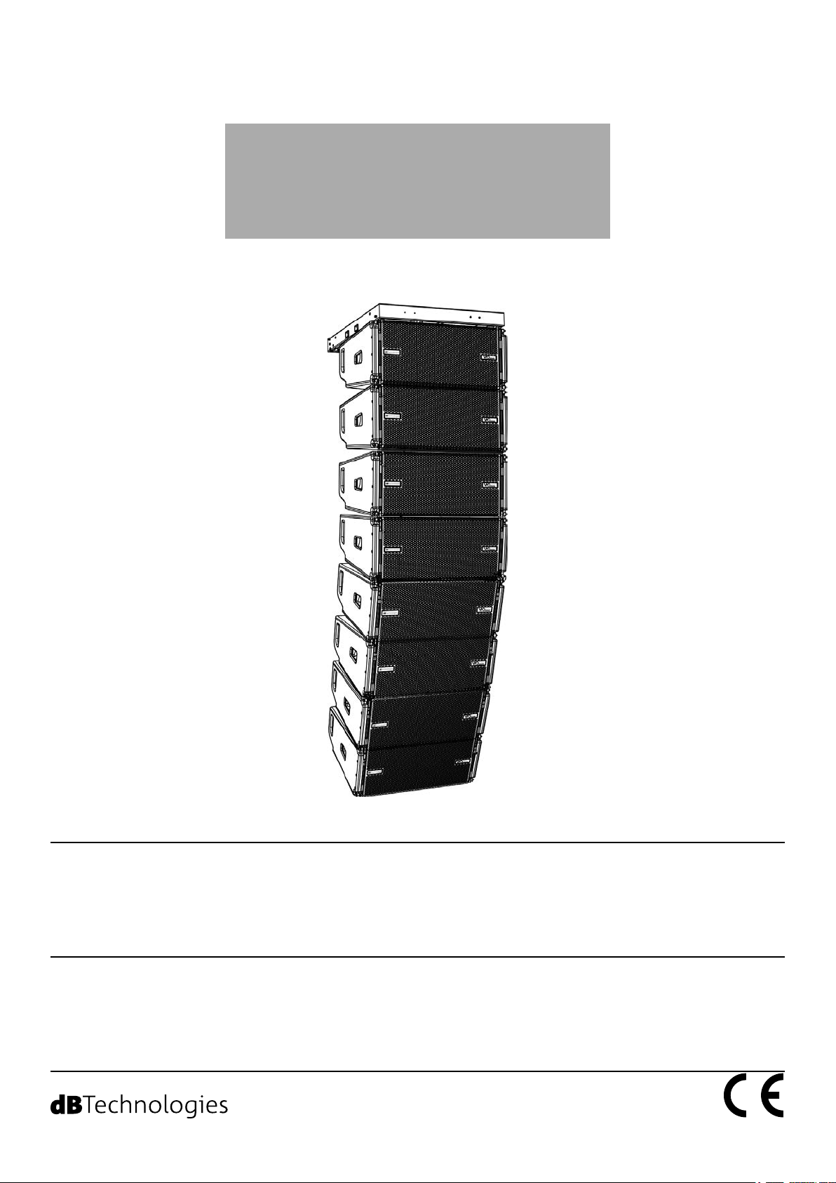
VIO-L210
2
Cod. 420120248 REV. 1.1
Page 3

ITALIANO
ENGLISH
DEUTSCH
FRANÇAIS
ESPAÑOL
VIO-L210 Cod. 420120248 REV. 1.1
3
Page 4

Italiano
INDICE
INDICE
1. INFORMAZIONI GENERALI ................................................................................................... 5
BENVENUTI! ........................................................................................................................ 5
PANORAMICA INTRODUTTIVA .......................................................................................... 5
RIFERIMENTI PER L’UTENTE ................................................................................................ 5
CARATTERISTICHE MECCANICHE ED ACUSTICHE ............................................................. 6
DIMENSIONI E PESO .................................................................................................................................. 6
CARATTERISTICHE ACUSTICHE .................................................................................................................. 6
MECCANICA ............................................................................................................................................... 7
ACCESSORI ............................................................................................................................................... 10
CARATTERISTICHE DELLA SEZIONE DI AMPLIFICAZIONE E DI CONTROLLO ................. 11
SEZIONE DI INPUT, OUTPUT E DI CONTROLLO ...................................................................................... 12
SEZIONE DI ALIMENTAZIONE .................................................................................................................. 13
2. DBTECHNOLOGIES COMPOSER .......................................................................................... 14
3. PARAMETRI DSP PRESET E CONTROLLO REMOTO .......................................................... 18
4. COLLEGAMENTI ................................................................................................................... 20
COLLEGAMENTO E RILANCIO DELL’ALIMENTAZIONE............................................................................. 20
COLLEGAMENTO E RILANCIO DEL SEGNALE AUDIO E RDNET .............................................................. 21
5. INSTALLAZIONE E CONFIGURAZIONE ............................................................................... 23
CONTENUTO DELLA CONFEZIONE .................................................................................. 23
INSTALLAZIONE FLOWN (ESEMPIO DI 1 ARRAY CON 8 MODULI) ................................. 23
INSTALLAZIONE STACKED (ESEMPIO DI 1 o 4 MODULI SU SUB318) ............................. 27
6. RISOLUZIONE DEI PROBLEMI ............................................................................................. 28
7. AGGIORNAMENTO DEL FIRMWARE .................................................................................. 29
8. SPECIFICHE TECNICHE ......................................................................................................... 30
GENERALE ................................................................................................................................................ 30
DATI ACUSTICI .......................................................................................................................................... 30
AMPLIFICATORE ....................................................................................................................................... 30
PROCESSORE ............................................................................................................................................ 31
INTERFACCIA UTENTE .............................................................................................................................. 31
INGRESSI ED USCITE ................................................................................................................................ 31
SPECIFICHE DI ALIMENTAZIONE (ASSORBIMENTO) ............................................................................... 31
SPECIFICHE MECCANICHE ....................................................................................................................... 32
VIO-L210
4
Cod. 420120248 REV. 1.1
Page 5

Italiano
1. INFORMAZIONI GENERALI
BENVENUTI!
Grazie per aver acquistato un prodotto progettato e sviluppato in Italia da dBTechnologies! Questo modulo
line-array attivo, potente e dal rapido montaggio, è frutto di una lunga esperienza nel campo della diffusione
sonora. Impiega soluzioni ottimizzate in campo acustico ed elettronico, oltre che nella scelta dei materiali.
PANORAMICA INTRODUTTIVA
Il modulo line-array attivo a 2 vie VIO-L210 inaugura una nuova stagione nel campo della diffusione sonora per le
applicazioni live indoor e outdoor di medie e grandi dimensioni. La famiglia VIO riassume innovazione tecnica e
design ottimizzato in un sistema dal suono straordinario, racchiuso in una meccanica dalle dimensioni contenute
e dal montaggio rapido e semplice. Le caratteristiche più salienti sono:
• progettazione acustica basata su guida d’onda e 2 phase plug ottimizzati, che rendono uniforme la
risposta in frequenza per una copertura audio precisa
• cabinet in legno con nitura in poliurea, per aumentare la durevolezza superciale
• sistema di appendimento a 3 punti per un rapido montaggio/smontaggio
• un amplicatore potente (900 W RMS) e silenzioso, che non necessita di ventilazione, e permette di
raggiungere un SPL di picco di 136 dB (a 1 m)
• un controllo afdato ad un potente DSP a 56 bit
• tecnologia Floating ADC, sviluppata per un perfetto isolamento da interferenze, rumori o ronzii,
dell’ingresso audio
• rilanci di alimentazione, audio e di rete per un cablaggio ottimizzato
• controllo RDNet on board e software predittivi e di gestione remota (DBTECHNOLOGIES COMPOSER,
EASE, EASE FOCUS 3, DBTECHNOLOGIES NETWORK)
RIFERIMENTI PER L’UTENTE
Per utilizzare al meglio il vostro diffusore VIO consigliamo di:
• leggere il manuale d’uso quick start presente nella confezione e questo manuale d’uso completo in
ogni sua parte e conservarlo per tutta la durata di vita del prodotto.
• registrare il prodotto sul sito http://www.dbtechnologies.com nella sezione “SUPPORTO”.
• conservare prova d’acquisto e GARANZIA (Manuale d’uso “sezione 2”).
VIO-L210 Cod. 420120248 REV. 1.1
5
Page 6
CARATTERISTICHE MECCANICHE ED ACUSTICHE
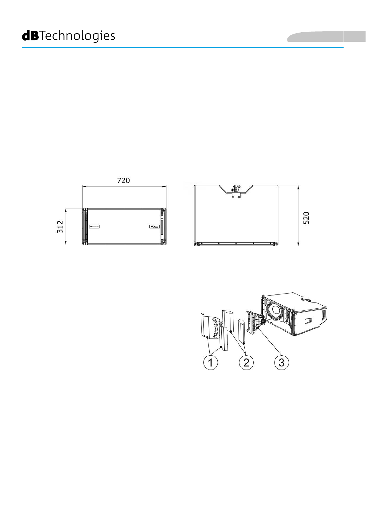
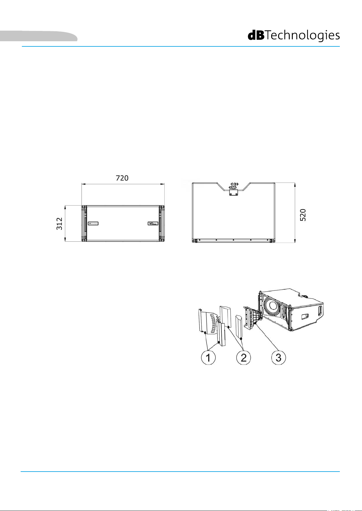
DIMENSIONI E PESO
La serie VIO è stata progettata con una particolare attenzione all’ottimizzazione di peso e ingombro.
Il cabinet in legno, rivestito in poliurea, pesa 28,6 kg.
Le misure sono: 720 mm (L), 312 mm (A), 520 mm (P).
Italiano
CARATTERISTICHE ACUSTICHE
L’ottimizzazione acustica parte da un’accurata scelta di
materiali, forma e geometria del cabinet in legno.
All’interno del modulo sono presenti diversi accorgimenti per
garantire accuratezza in un range di frequenze molto esteso.
In particolare, i 2 woofer da 10” di elevata qualità con
magneti al neodimio e il compression driver da 3” in titanio
(uscita da 1/4”), sono ottimizzati grazie a:
1) due PHASE PLUG in alluminio (con fori a diamante),
che avvicinano i punti di emissione delle basse frequenze,
aumentando la coerenza nell’ascolto fuori asse.
2) foam in materiale fonoassorbente, utilizzati per eliminare
riessioni interne ai phase plug.
3) una guida d’onda disegnata per controllare la direttività
verticale sulle alte frequenze ed ottenere un fronte d’onda
cilindrico.
Questi dettagli consentono un perfetto matching tra i moduli,
permettendo così una risposta in frequenza ottimale, sia a
distanza, sia nell’ascolto fuori asse.
VIO-L210
6
Cod. 420120248 REV. 1.1
Page 7

Italiano
MECCANICA
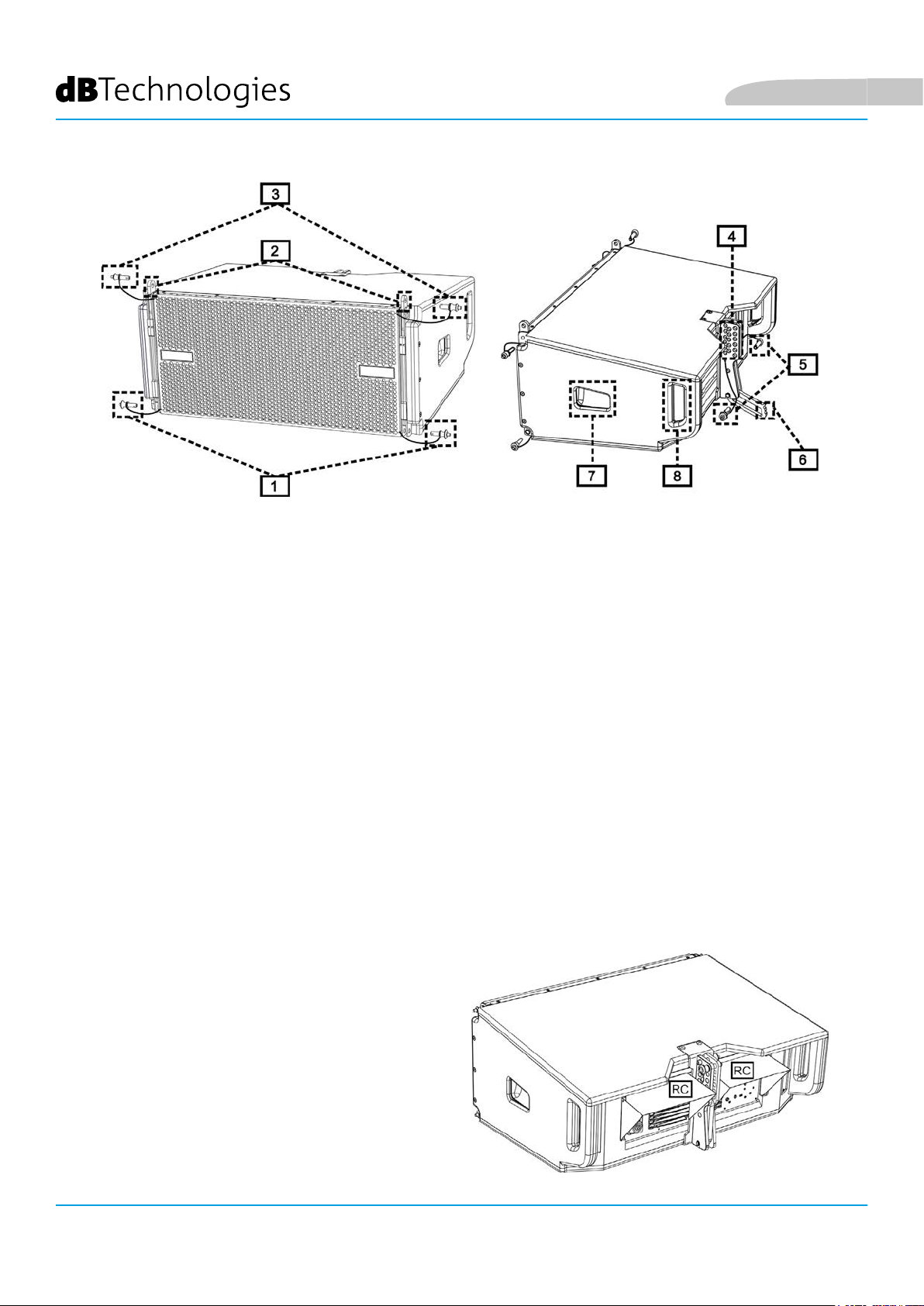
L’ergonomia del modulo ed il rapido montaggio in line-array sono garantiti da:
LATO ANTERIORE
1) Sistema di ancoraggio inferiore per collegare altri moduli o il y-bar DRK-210 (in congurazione stacked).
2) Staffe a scomparsa per l’ancoraggio ad un modulo superiore (o al y-bar DRK-210 in congurazione
own).
3) Pin per il ssaggio in posizione aperta/chiusa delle staffe a scomparsa [2].
LATO POSTERIORE
4) Staffa centrale. Dotata di etichetta graduata, permette di selezionare l’angolazione del modulo line-array.
Sono possibili step da 1° (range: 0-10°).
5) Pin per il ssaggio dell’angolo di inclinazione: è necessario inserire 1 solo pin in congurazione own, 2
in quella stacked. Vedere al proposito le gure a pagina 9.
6) Braccio mobile con asola. Inserito nella staffa [4], ssa meccanicamente l’angolo prescelto tramite
i pin [5].
LATO DESTRO E SINISTRO
7) Maniglia in posizione bilanciata rispetto al peso del cabinet.
8) Maniglia in posizione arretrata nel cabinet, che agevola il sollevamento di un modulo sul retro, quando il
lato anteriore è ssato.
I moduli VIO-L210 sono anche provvisti sul
lato posteriore di 2 rain cover, per proteggere
l’amplicatore dall’acqua ed operare anche in
condizioni meteo critiche. Nelle illustrazioni
successive, per semplicità, non saranno più mostrati.
Per ulteriori informazioni sul y-bar (vedere la sezione
ACCESSORI) fare riferimento al manuale relativo.
VIO-L210 Cod. 420120248 REV. 1.1
7
Page 8
Italiano
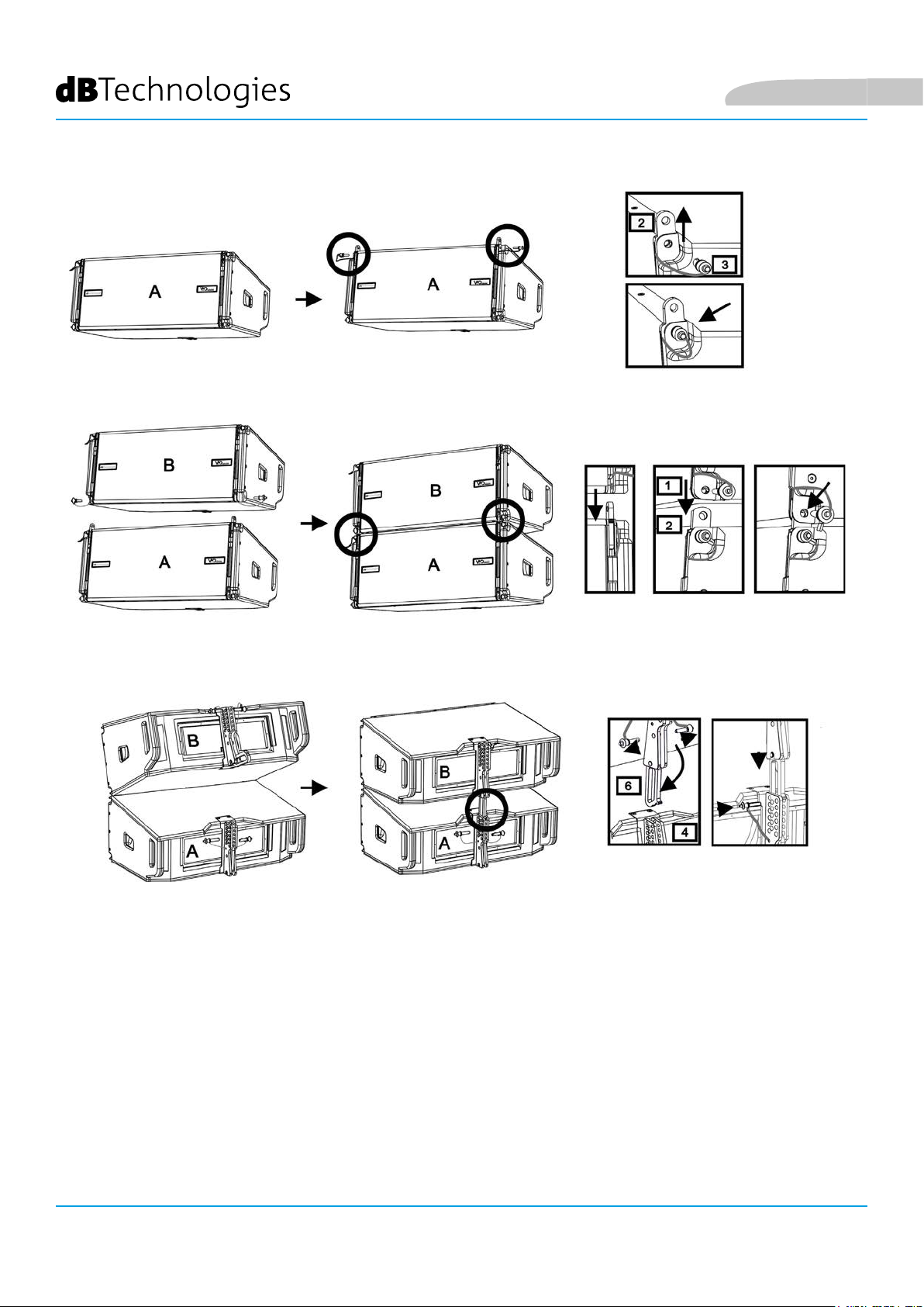
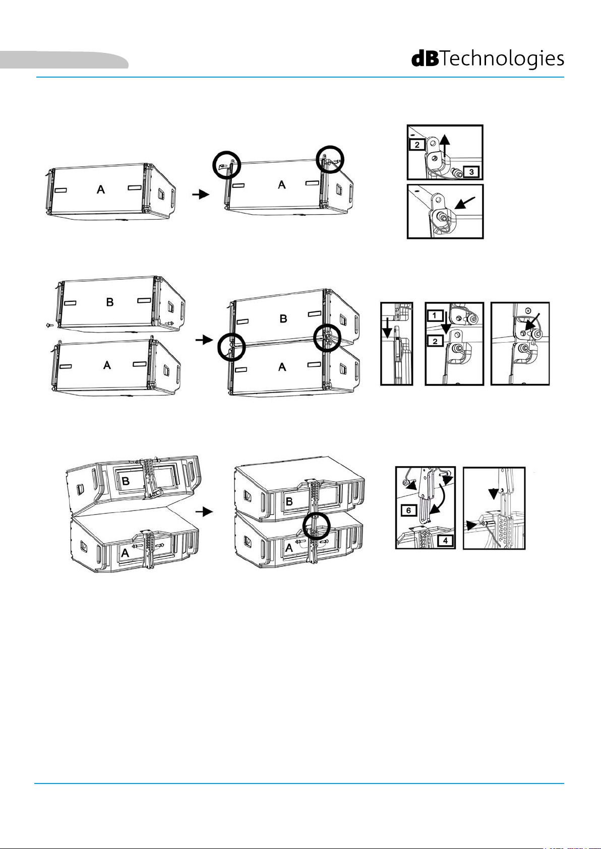
Il montaggio di 2 moduli A e B prevede pochi semplici passi:
• Sul modulo A estrarre i pin [3], alzare le staffe a scomparsa [2] e ssarle nella nuova posizione coi i pin [3].
• Estrarre i pin [1] nel modulo B, sovrapporlo al modulo A, inserendo le staffe [2] come mostrato. Fissare
quindi il lato anteriore dei due moduli con i pin [1] del modulo B.
• Sul retro, estrarre i pin [5] dalle staffe posteriori [4]. Inserire quindi il braccio mobile [6] del modulo B nella
staffa [4] del modulo A. Nella pagina successiva è mostrato il dettagli del ssaggio dell’angolo sul retro tra
i due moduli.
VIO-L210
Cod. 420120248 REV. 1.1
8
Page 9

Italiano
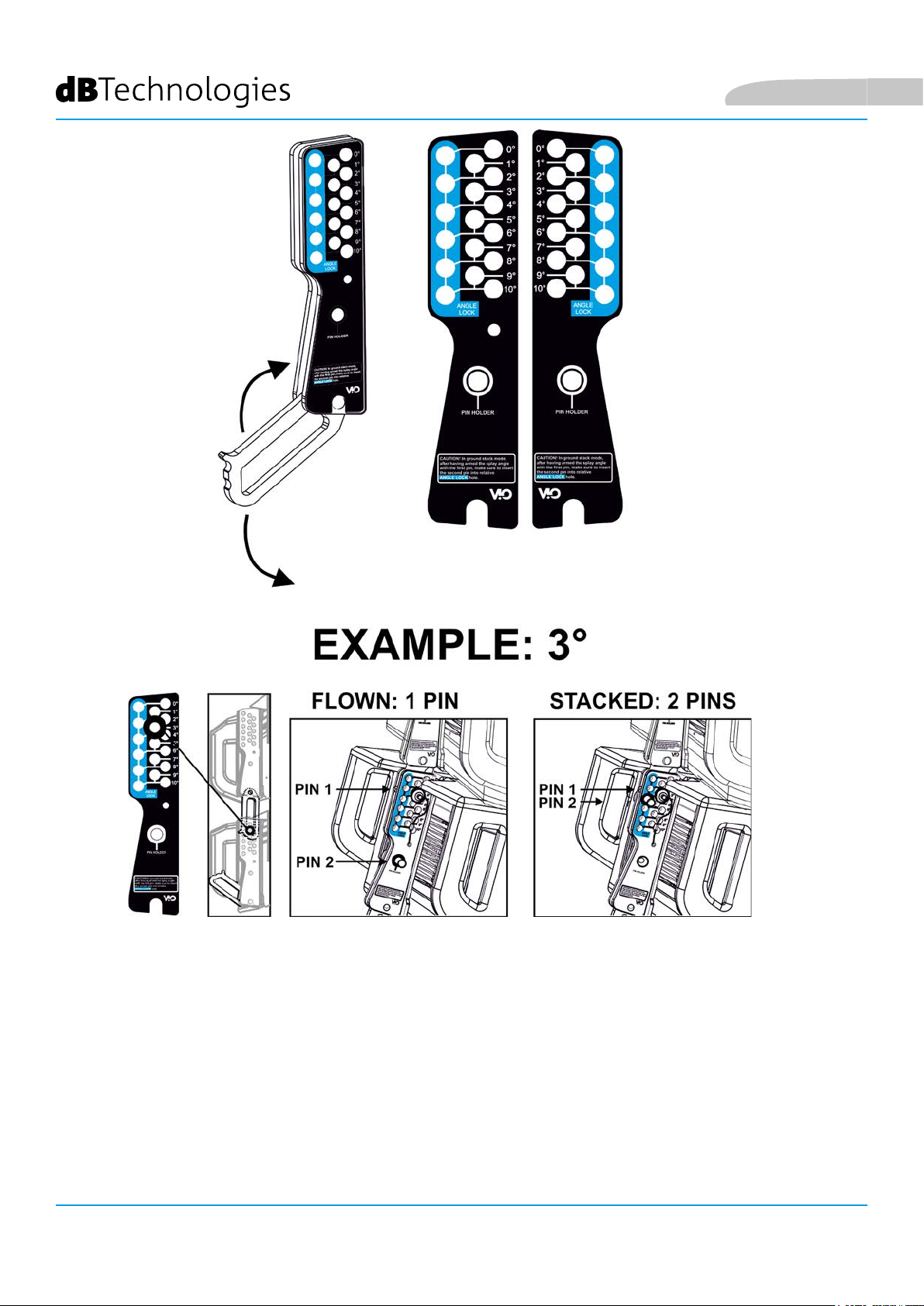
ATTENZIONE! ESEMPIO: 3°
Nell’esempio è mostrato il caso in cui si voglia impostare un angolo di 3° tra 2 moduli.
Prima di ogni altra operazione vericare che, una volta inserito il braccio mobile [6], il foro dell’angolo prescelto
risulti contenuto all’interno dell’asola come mostrato.
• CASO FLOWN: inserire 1 solo pin nel foro relativo all’angolo scelto. Il secondo pin può essere alloggiato nel
foro “PIN HOLDER”. Notare che questo tipo di congurazione in fase di montaggio permette di cambiare
l’angolazione scelta semplicemente spostando il pin relativo (a braccio mobile inserito).
• CASO STACKED: una volta inserito un pin [5] nel foro dell’angolo prescelto, sollevare il modulo B nchè
il braccio mobile [6] lo permette. A questo punto inserire il secondo pin nella posizione “ANGLE LOCK” e
rilasciare il modulo B. In questo modo il modulo B risulta completamente bloccato sul retro grazie ai 2 pin.
Assicurarsi sempre a ne montaggio che tutti i pin siano stati inseriti completamente e risultino bloccati.
VIO-L210 Cod. 420120248 REV. 1.1
9
Page 10
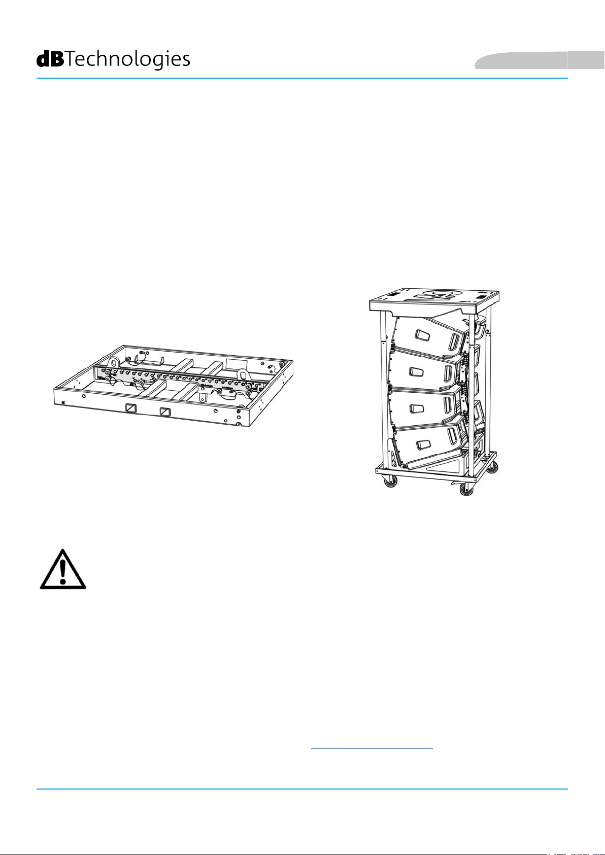
ACCESSORI
Per un rapido montaggio, sono previsti come opzionali i seguenti accessori:
• DRK-210, y-bar per l’utilizzo own e stacked dei line array di moduli VIO-L210.
• DT-VIOL210, carrello per trasportare no a 4 moduli VIO-L210. Grazie a questo accessorio è possibile
montare sul coperchio, esclusivamente per il trasporto, 1 y-bar DRK-210.
Italiano
DRK-210
DT-VIOL210
ATTENZIONE!
• Utilizzare solo gli accessori e le congurazioni indicate nel presente manuale ed operare in
accordo a quanto indicato nei manuali relativi agli accessori.
• DRK-210 è stato progettato per sospendere no a 25 VIO L210 (oppure 16 moduli Sub) per un
massimo di 750 kg con un singolo punto di aggancio.
I componenti di sospensione del VIO L210 permettono di connettere no a 10 moduli (max
300 kg) senza limiti sull’angolazione del line array. Ogni altra congurazione o informazione
sui dati del sistema, come la portata massima e i punti di aggancio, deve essere vericata prima
dell’installazione con il software dBTechnologies Composer (vedi il paragrafo relativo in questo
manuale d’uso). E’ disponibile gratuitamente sul sito www.dbtechnologies.com nella sezione
DOWNLOAD.
Per ogni ulteriore informazione si prega di consultare i manuali relativi.
Per tutti gli aggiornamenti sugli accessori consultare il sito www.dbtechnologies.com
VIO-L210
10
Cod. 420120248 REV. 1.1
Page 11
Italiano
CARATTERISTICHE DELLA SEZIONE DI AMPLIFICAZIONE E DI CONTROLLO
L’amplicatore digitale in classe D è il cuore dei moduli VIO-L210.
Permette di eorgare no a 900 W RMS, in modo silenzioso
ed efciente, non necessitando di un sistema di ventilazione.
Il controllo del sistema è afdato a un potente DSP che rende
possibile congurare in modo immediato e veloce il
line-array in qualsiasi contesto di utilizzo.
Grazie alla possibilità di collegamento in rete con RDNet, i
parametri sul pannello possono essere controllati in remoto,
grazie al software “DBTECHNOLOGIES NETWORK” (vedere il
paragrafo PARAMETRI DSP PRESET E CONTROLLO REMOTO).
Il pannello del DIGIPRO G3 è caratterizzato da:
• Sezione di Input, Output e Controllo
• Sezione di Alimentazione
ATTENZIONE!
• Non ostruire le alette posteriori di
raffreddamento dell’amplicatore. In caso
di surriscaldamento eccessivo, il volume
audio viene ridotto gradualmente no
alla stabilizzazione termica del modulo. Il
livello viene ristabilito automaticamente al
raggiungimento della corretta temperatura di
funzionamento.
• Non tentare in nessun modo di aprire
l’amplicatore.
• In caso di malfunzionamento, interrompere
immediatamente l’alimentazione, scollegando
il modulo dalla rete, e contattare un riparatore
autorizzato.
• Utilizzare preferibilmente cavi dotati di
connettori originali Neutrik®, di alta qualità.
Controllarne periodicamente l’integrità.
• Il diffusore viene fornito con un fusibile già
montato per operare nel range 220-240 V. Se è
necessario operare nel range di tensione 100-120
V:
1. Disconnettere ogni connessione,
compresa l’alimentazione.
2. Attendere 5 minuti.
3. Sostituire il fusibile con quello fornito
nella confezione per il range 100-120 V.
ATTENZIONE!
• Non rimuovere mai la griglia frontale di protezione del prodotto.
Per prevenire il pericolo di scossa elettrica, in caso di danneggiamento accidentale o sostituzione
della griglia di protezione (da effettuarsi presso il servizio assistenza) , disconnettere
immediatamente l’alimentazione.
Non connettere mai l’alimentazione di rete mentre la griglia è rimossa.
SEZIONE DI
CONTROLLO
INGRESSO, USCITA E
SEZIONE DI
ALIMENTAZIONE
VIO-L210 Cod. 420120248 REV. 1.1
11
Page 12
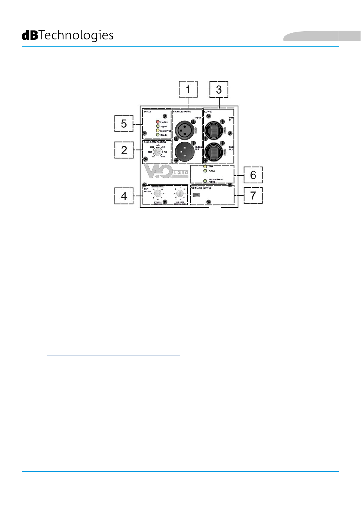
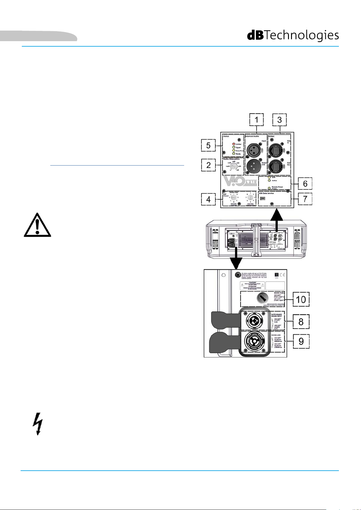
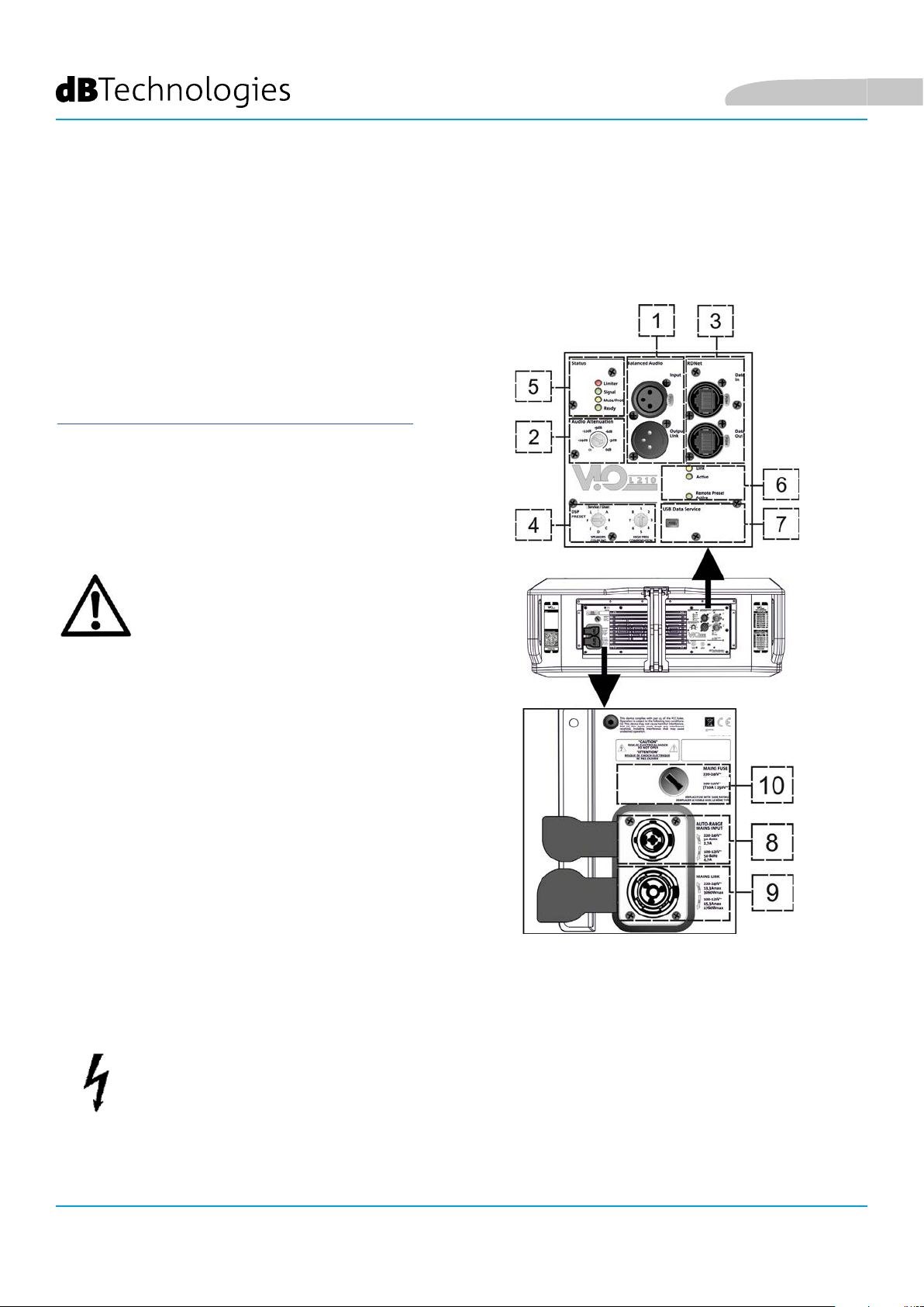
SEZIONE DI INPUT, OUTPUT E DI CONTROLLO
Italiano
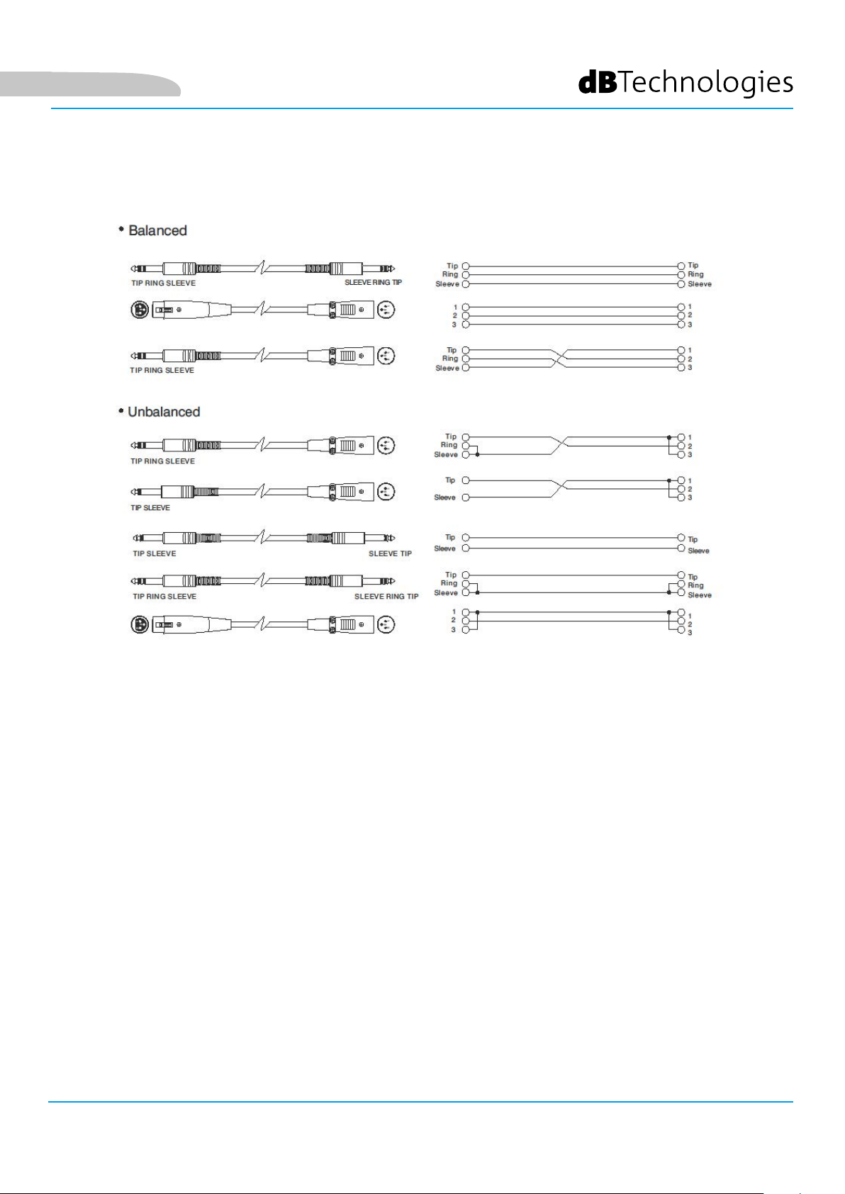
1. INGRESSO E RILANCIO AUDIO (“Balanced audio”)
Ingresso e uscita compatibili con cavi XLR blanciati.
In particolare, “Input” è utilizzato per il collegamento con il segnale audio proveniente dal mixer o da un altro
diffusore, “Output Link” per il rilancio del segnale agli altri moduli del line-array. in congurazione daisy-chain.
2. AUDIO ATTENUATION
Permette di regolare l’attenuazione del modulo agendo sul volume di ingresso.
Porre a 0 dB prima di iniziare il montaggio del line-array.
3. INGRESSO E RILANCIO DELLA CONNESSIONE DI RETE RDNet
Sezione compatibile con cavi di rete dotati di connettori di tipo etherCON/RJ45.
In particolare “Data in” deve essere collegato a dispositivi come RDNet Control 2 o Control 8, “Data Out” viene
utilizzato per il rilancio della rete ad ulteriori moduli del line-array in congurazione daisy-chain.
4. DSP PRESET
Rotary per il setup acustico del line-array.
E’ opportuno utilizzare questi controlli (o gli stessi parametri in remoto tramite connessione RDNet) per
ottimizzare il comportamento acustico in funzione del numero di moduli ed al loro puntamento. Un
approfondimento sull’utilizzo di “SPEAKER COUPLING” e “HIGH FREQUENCY COMPENSATION” è presente nella
sezione “PARAMETRI DSP PRESET E CONTROLLO REMOTO”.
5. LED DI STATO
Led relativi al funzionamento del modulo. Una tabella nella pagina seguente riepiloga e sintetizza il signicato
dei vari LED.
6. LED DI CONTROLLO
Led relativi al funzionamento in rete (RDNet) del modulo.
In particolare, “Link” acceso segnala che la rete RDNet è attiva e ha riconosciuto il dispositivo, “Active” in modalità
lampeggiante che esiste trafco dati, “Remote Preset Active” che tutti i controlli locali sul pannello amplicatore
sono by-passati dal controllo remoto RDNet.
7. USB DATA SERVICE
Porta di tipo mini-USB B, da utilizzare esclusivamente per l’aggiornamento del rmware del prodotto. Vedi la
sezione “AGGIORNAMENTO DEL FIRMWARE” per ulteriori informazioni.
VIO-L210
Cod. 420120248 REV. 1.1
12
Page 13
Italiano
TIPO LED FASE DI ACCENSIONE
DELLO SPEAKER
IN FUNZIONE
NORMALE
WARNING
GENERICO
BLOCCO PER
ANOMALIA DELLO
SPEAKER
LIMITER SPENTO SPENTO, SI
ACCENDE SOLO
IN CASO DI
INTERVENTO
SIGNAL
MUTE/
PROT
READY SPENTO ACCESO FISSO ACCESO FISSO SPENTO
SPENTO LAMPEGGIO
ACCESO PER QUALCHE
SECONDO
Tabella di segnalazione dei LED di stato
IN PRESENZA DI
SEGNALE
SPENTO LAMPEGGIO
LAMPEGGIO
MOMENTANEO
SEGNALAZIONE
NORMALE DI
AUDIO IN
INGRESSO
MOMENTANEO
LAMPEGGIO CICLICO
CONTINUO
SPENTO
ACCESSO FISSO
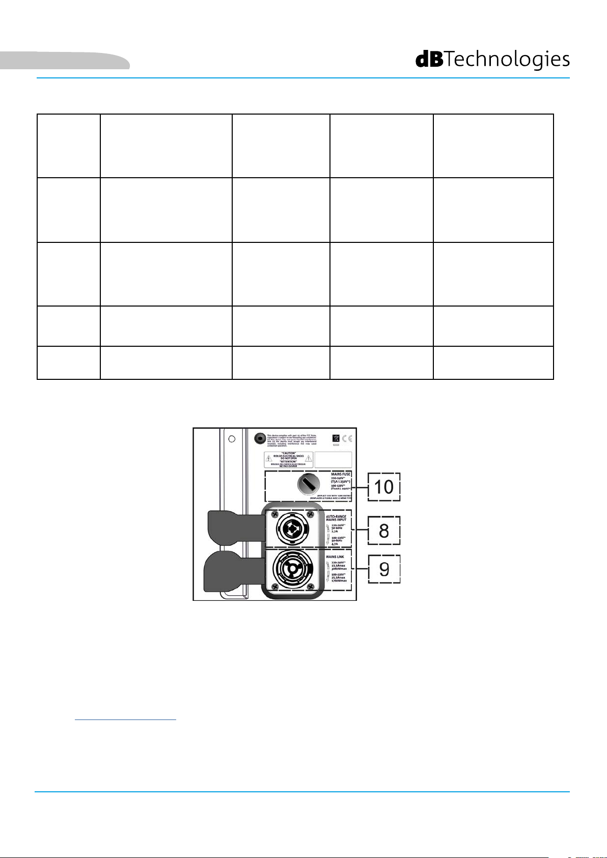
SEZIONE DI ALIMENTAZIONE
8. CONNETTORE DI ALIMENTAZIONE “MAINS INPUT”
Compatibile con connettore powerCON TRUE1®, l’alimentazione è dotata di funzione autorange. Una volta
denito il range opportuno con l’eventuale cambio del fusibile, riconosce automaticamente la tensione
all’interno dell’intervallo [100-120V~] oppure [220-240V~].
9. RILANCIO DI ALIMENTAZIONE “MAINS LINK”
Compatibile con connettore tipo powerCON TRUE1® per il rilancio dell’alimentazione ad altri moduli.
Per conoscere il numero massimo di moduli che si possono connettere in un sistema rilanciato, consultare la
sezione SPECIFICHE TECNICHE.
10. FUSIBILE DI RETE
Alloggio per il fusibile di rete.
VIO-L210 Cod. 420120248 REV. 1.1
13
Page 14

2. DBTECHNOLOGIES COMPOSER
Il software dBTechnologies Composer, gratuitamente scaricabile dal sito www.dbtechnologies.com, è lo
strumento per la corretta progettazione di sistemi audio consigliato per tutta la serie VIO.
Suggerisce la soluzione per gli spazi da sonorizzare, indicando l’angolazione dei moduli del line-array per
ottenere la copertura desiderata ed il preset da utilizzare.
Pur essendo uno strumento predittivo, permette comunque una serie di regolazioni manuali per
perfezionare la congurazione in base ad eventuali misure audio effettuate sul campo, o a speciche
esigenze.
E’ inne lo strumento efcace per valutare la sicurezza dell’installazione. Grazie infatti a una simulazione
del comportamento statico dei y-bar ed una indicazione delle forze meccaniche in gioco permette di
vericare quanti moduli installare prima di arrivare ad una condizione di sovraccarico.
Le sezioni principali di dBTechnologies Composer sono:
• COMPOSER - vista generale che permette l’inserimento dei dati iniziali di progetto
• LAs PREDICT - con la simulazione, congurazione e verica di sicurezza dei line-array
• SUBs PREDICT - con la simulazione, congurazione e verica di sicurezza dei subwoofer
Italiano
In questo capitolo vengono evidenziati alcuni dettagli del software relativi al montaggio e alla sicurezza, in
particolare per la congurazione FLOWN dei line-array VIOL210.
VIO-L210
14
Cod. 420120248 REV. 1.1
Page 15

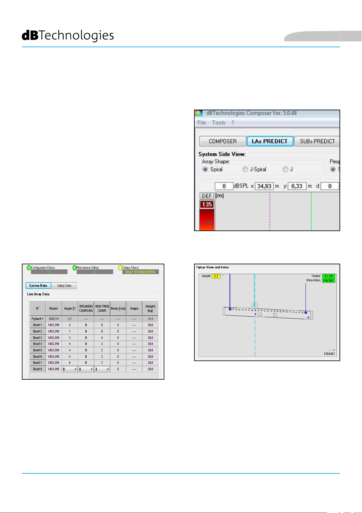
Italiano
La sezione LAs PREDICT contiene tutte le informazioni per la corretta congurazione own o stack di un
sistema VIO. Per accedervi occorre completare prima l’inserimento dei dati di progetto, presenti nella
sezione Composer.
Nella sottopagina System Data, vengono suggeriti: l’angolazione dei vari moduli, vari parametri relativi
alla sezione “DSP preset” e l’angolazione del y-bar DRK-210. Quest’ultima angolazione può essere rilevata
sul campo tramite l’utilizzo di un inclinometro laser non incluso, il cui montaggio è illustrato nel manuale
di DRK-210.
VIO-L210 Cod. 420120248 REV. 1.1
15
Page 16
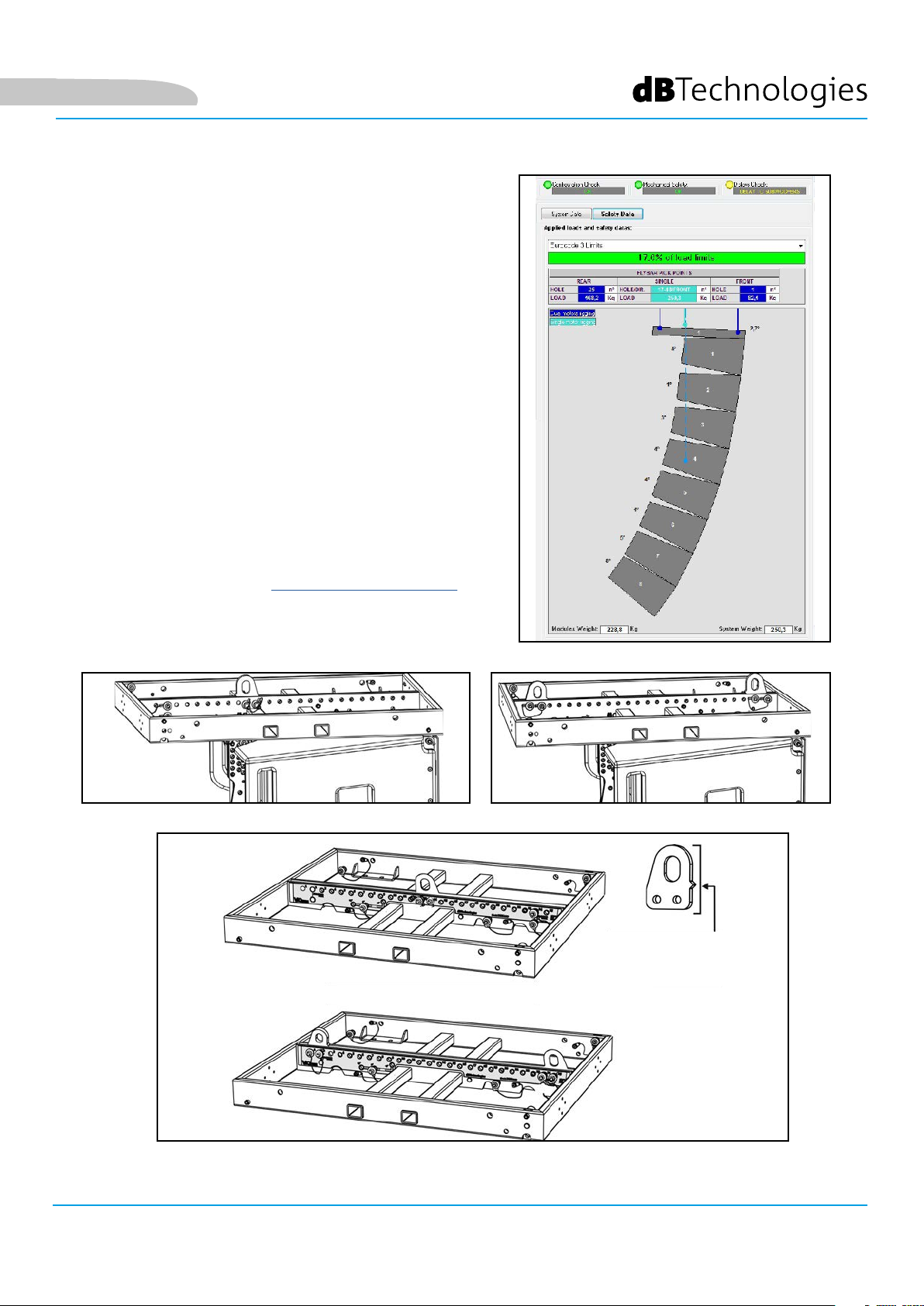
Nella sezione Safety Data, è possibile trovare una
simulazione del centro di gravità del sistema own con
DRK-210.
In particolare, l’utente può scegliere fra i riferimenti
EUROCODE 3 o BGV-C1.
I risultati relativi sono evidenziati in colore verde se sicuri,
in colore rosso se si eccede il carico massimo ammesso
per l’angolazione prescelta (e di cui pertanto è vietato
l’utilizzo).
Italiano
VIO-L210
16
Cod. 420120248 REV. 1.1
Page 17
Italiano
Nel caso in cui, in congurazione own, si utilizzi un solo
motore, “SINGLE” indica la posizione del gancio singolo
da utilizzare su DRK-210 (che prevede posizioni graduate
descritte da un’etichetta posta sul y-bar stesso).
Inoltre esiste un verso “FRONT” o “REAR” relativo a come
si orienta il gancio per il motore.
Nel caso “FRONT” il riferimento (mostrato nella gura
sotto e indicato come LOAD ADAPTOR REFERENCE SIDE),
va posto verso il lato frontale del line-array, in caso
“REAR” va orientato verso il lato posteriore del line array.
In caso si utilizzino due motori invece, i ganci risultano
sempre posti agli estremi del y-bar (in questo caso è
indifferente il verso di posizionamento).
Per ogni altro dettaglio sul software dBTechnologies
Composer, consultare il manuale relativo, scaricabile
gratuitamente all’indirizzo: www.dbtechnologies.com.
ETICHETTA GRADUATA SU UN LATO DEL FLY-BAR
LOAD ADAPTOR REFERENCE SIDE
VIO-L210 Cod. 420120248 REV. 1.1
17
Page 18
Italiano
3. PARAMETRI DSP PRESET E CONTROLLO REMOTO
L’utilizzo di un line-array comporta una serie di vantaggi in diversi contesti, in particolare:
• SPL omogeneo lungo la direttrice frontale degli speaker, effetto che si apprezza in particolare su
distanze medio-lunghe
• comportamento acustico direttivo, che permette di focalizzare in maniera precisa il suono sul pubblico,
evitando inutili dispersioni in zone dove una copertura acustica non è richiesta.
L’ottimizzazione attuabile del line-array tiene conto del comportamento del sistema rispetto alla frequenza:
• all’aumentare della distanza dal line-array aumenta l’attenuazione dell’aria. Questo ha effetto in
particolare sulle alte frequenze.
• all’aumentare dell’angolazione tra elementi del line-array diminuisce l’accoppiamento in fase delle
medie frequenze.
• all’aumentare del numero di moduli del line-array le basse frequenze si sommeranno in maniera
acusticamente coerente.
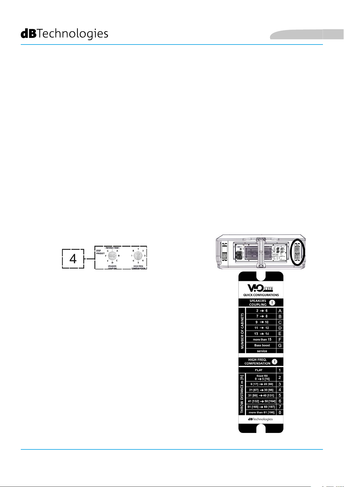
La congurazone acustica in line-array dei moduli VIO L210 può essere ottimizzata, grazie alle funzioni
di controllo gestite dal DSP. L’interfaccia per l’utilizzo è semplice e immediata: impiega due rotary della
sezione “DSP Preset” (4) e fa riferimento all’etichetta esplicativa posta a lato dell’amplicatore :
• Posizionare il rotary “SPEAKER COUPLING” in base al numero di
moduli impiegati nel line array. Questo rotary agisce sulle basse
frequenze e va impostato nella posizione:
• A - da 2 a 6 speaker
• B - da 7 a 8 speaker
• C - da 9 a 10 speaker
• D - da 11 a 12 speaker
• E - da 13 a 14 speaker
• F - da 15 in poi
• G - per esaltare le basse frequenze (front ll
oppure nell’utilizzo stand-alone)
VIO-L210
18
Cod. 420120248 REV. 1.1
Page 19
Italiano
• Posizionare il rotary “HIGH FREQUENCY COMPENSATION” in
base al tipo di installazione ed angolazione impostata nel
line-array. Questo rotary agisce sulla sezione delle medio-alte
frequenze e va impostato nella posizione:
• 1 - FLAT (non c’è enfasi su nessuna particolare banda di frequenze)
• 2 - front ll con pubblico distante da 0 a 5 m (16 piedi)
• 3 - con pubblico a distanza tra 6-20 m (17-66 piedi)
• 4 - con pubblico a distanza tra 21-30 m (67-98 piedi)
• 5 - con pubblico a distanza tra 31-40 m (99-131 piedi)
• 6 - con pubblico a distanza tra 41-50 m (132-164 piedi)
• 7 - con pubblico a distanza tra 51-60 m (165-197 piedi)
• 8 - con pubblico a distanza a partire da 61 m (198 piedi)
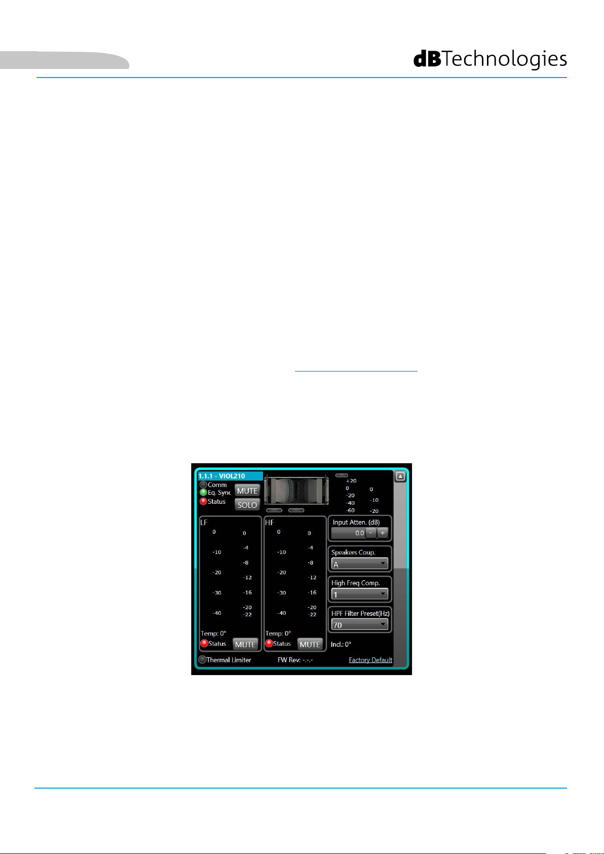
• Tutti questi parametri possono essere regolati attraverso il controllo remoto, una volta effettuate
correttamente le connessioni RDNet, attraverso l’utilizzo del software gratuito DBTECHNOLOGIES
NETWORK (scaricabile gratuitamente dal sito www.dBTechnologies.com nella sezione
DOWNLOAD). Quando il controllo è remoto, i controlli locali presenti sui pannelli dei moduli
VIO-L210 sono by-passati. Grazie all’utilizzo di questo software, inoltre è possibile controllare un
numero maggiore di parametri (per ulteriori informazioni si rimanda al manuale completo di
DBTECHNOLOGIES NETWORK).
Le ultime impostazioni scelte e salvate sui moduli VIOL210 (con l’utilizzo di
DBTECHNOLOGIES NETWORK), possono essere successivamente richiamate sullo speaker in
assenza di controllo remoto RDNet. E’ sufciente ruotare il rotary SPEAKER COUPLING sulla
posizione Service/User.
VIO-L210 Cod. 420120248 REV. 1.1
19
Page 20
4. COLLEGAMENTI
COLLEGAMENTO E RILANCIO DELL’ALIMENTAZIONE
Italiano
A
MODULO 1
B
C
MODULO 2
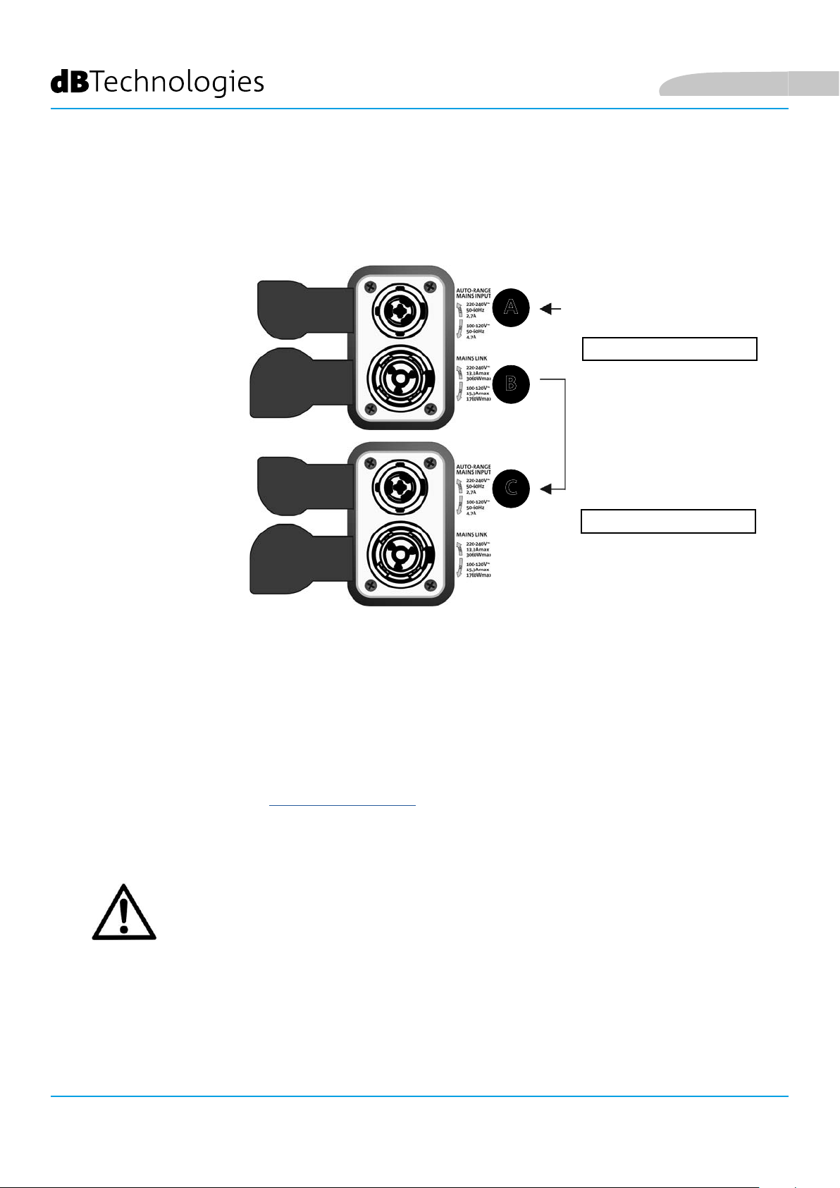
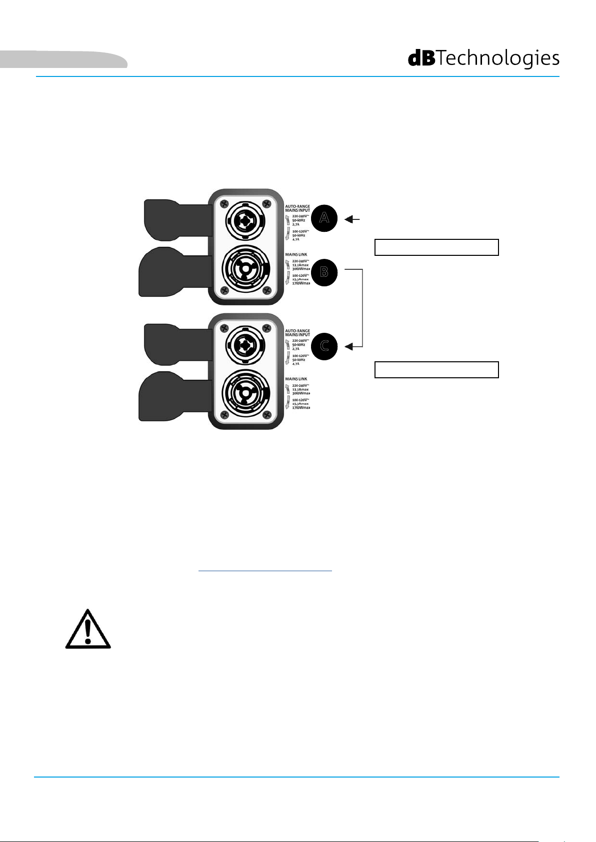
Nell’illustrazione sopra è mostrato un generico caso di collegamento in cui un modulo 1
è sopra al modulo 2. Utilizzare allo scopo cavi con connettori powerCON TRUE1® (non forniti).
• Collegare l’alimentazione del modulo 1 AUTO-RANGE MAINS INPUT (A).
• Rilanciare l’alimentazione dal modulo 1 al modulo 2, collegando l’uscita MAINS LINK (B)
del modulo 1 all’ingresso AUTO-RANGE MAINS INPUT (C) del modulo 2.
• Ripetere quest’ultima operazione no a collegare il numero massimo ammesso di moduli del linearray (vedere il capitolo SPECIFICHE TECNICHE).
ATTENZIONE!
• I cavi devono essere opportunamente dimensionati e la progettazione,
installazione e verica dell’impianto devono essere effettuate esclusivamente
da personale qualicato. AEB industriale declina ogni responsabilità in caso
di utilizzo di cavi non idonei, non certicati e non compatibili col corretto
dimensionamento dell’impianto e le normative in vigore per il Paese di utilizzo.
VIO-L210
20
Cod. 420120248 REV. 1.1
Page 21
Italiano
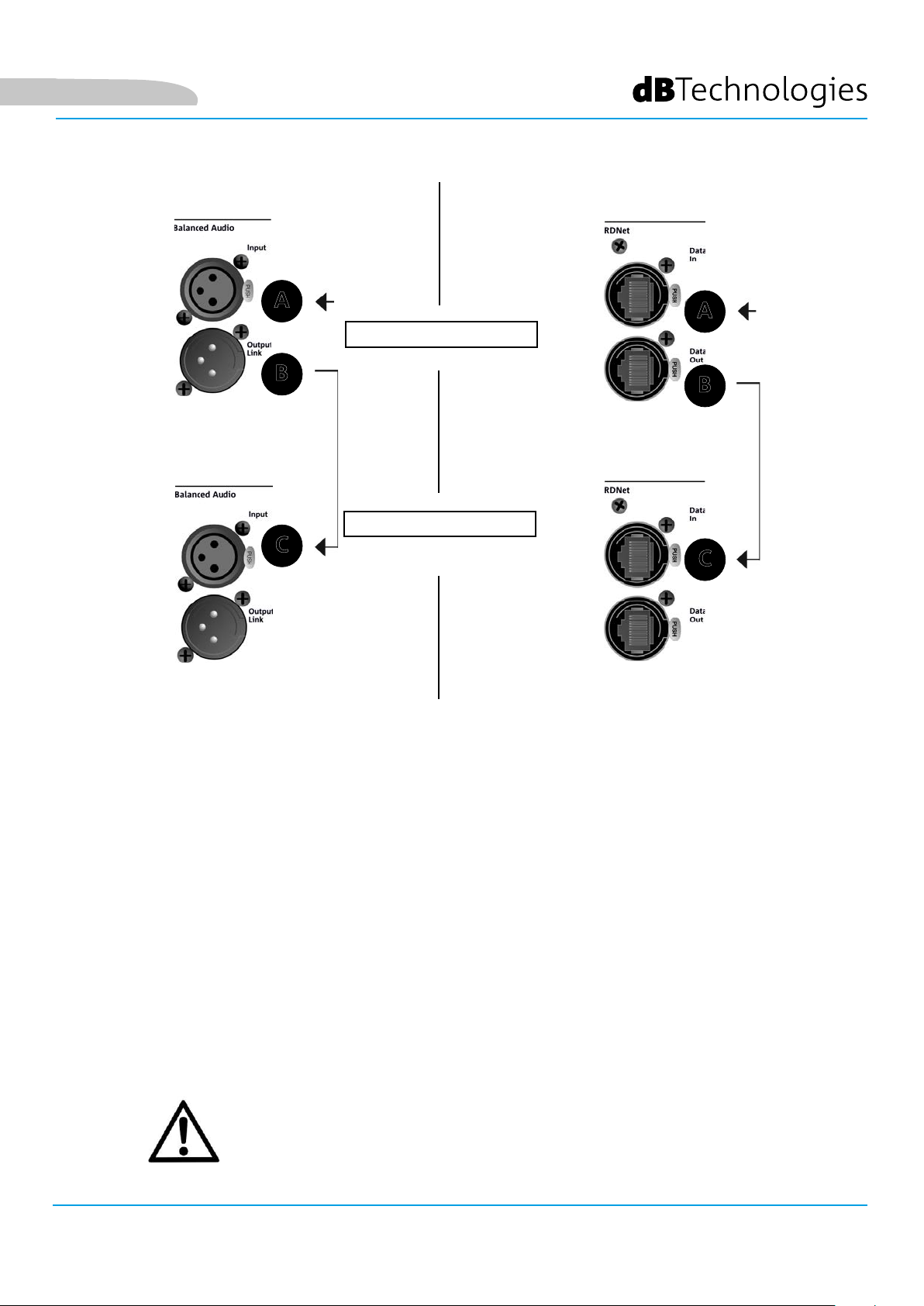
COLLEGAMENTO E RILANCIO DEL SEGNALE AUDIO E RDNET
A
MODULO 1
B
MODULO 2
A
B
C
C
Nell’illustrazione sopra è mostrato un generico caso di collegamento in cui un modulo 1
è sopra al modulo 2, questa volta illustrando i collegamenti audio e di rete. Utilizzare allo scopo cavi
non forniti, con connettori XLR (audio) e etherCON/RJ45 (rete). Per ulteriori informazioni sui tipi di
cavi disponibili confrontare anche l’immagine nella pagina seguente.
• Per la connessione audio, collegare il cavo proveniente da MIXER/LINE all’ingresso BALANCED
AUDIO INPUT (A) del modulo 1 del line array. Rilanciare il segnale tra il primo e il secondo
modulo. A questo scopo collegare l’uscita BALANCED AUDIO OUTPUT/LINK (B) del modulo 1
all’ingresso BALANCED AUDIO INPUT (C) del modulo 2.
• Ripetere l’operazione tra il secondo e il terzo modulo, e così via, no a collegare tutti i moduli del
line-array.
• Per la connessione di rete, collegare il connettore DATA IN (A) del modulo 1 al controller remoto
(RDNet CONTROL 2 oppure RDNet CONTROL 8). Rilanciare il segnale collegando DATA OUT (B) del
modulo 1 a DATA IN (C) del modulo 2.
• Ripetere l’operazione tra il secondo e il terzo modulo, e così via, no a collegare tutti i moduli del
line-array.
ATTENZIONE!
• Sostituire i cavi eventualmente danneggiati, per evitare malfunzionamenti ed
una scarsa qualità del suono.
VIO-L210 Cod. 420120248 REV. 1.1
21
Page 22

Italiano
VIO-L210
Cod. 420120248 REV. 1.1
22
Page 23
Italiano
5. INSTALLAZIONE E CONFIGURAZIONE
CONTENUTO DELLA CONFEZIONE
Vericate che il contenuto dell’imballo del modulo VIO-L210 sia completo. L’imballo contiene:
• Modulo VIO-L210
• fusibile per il funzionamento nel range 110-120V~ (vedere la sezione CARATTERISTICHE DELLA SEZIONE
DI AMPLIFICAZIONE E DI CONTROLLO per ulteriori informazioni)
• quick start e documentazione relativa alla garanzia
ATTENZIONE!
Il prodotto e gli accessori devono essere utilizzati solo da personale esperto! Assicurarsi che l’installazione
sia posizionata in modo stabile e sicuro per scongiurare ogni condizione di pericolo per persone, animali e/o
cose. L’utilizzatore è tenuto a seguire le regolamentazioni e le leggi cogenti in materia di sicurezza nel Paese
in cui si utilizza il prodotto. Per l’utilizzo in sicurezza, vericare periodicamente la funzionalità di tutte le parti
e l’integrità prima dell’utilizzo.
La progettazione, i calcoli, l’installazione, il collaudo e la manutenzione di sistemi sospesi o stack audio professionali deve essere effettuata esclusivamente da personale autorizzato. AEB Industriale non è responsabile
per installazioni improprie, effettuate in assenza dei requisiti di sicurezza.
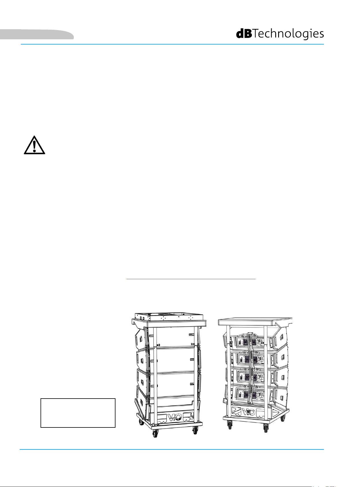
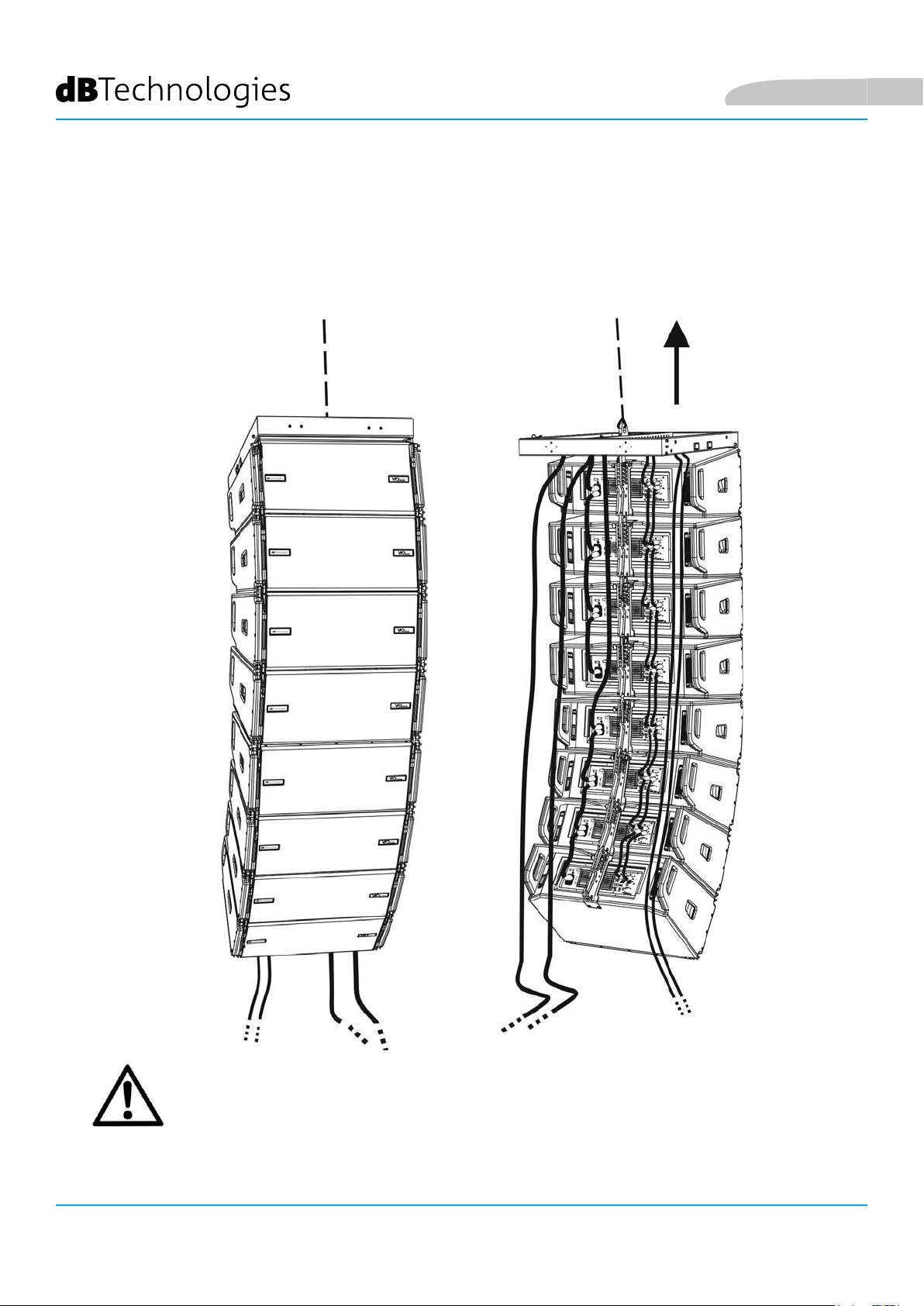
INSTALLAZIONE FLOWN (ESEMPIO DI 1 ARRAY CON 8 MODULI)
• Utilizzare DBTECHNOLOGIES COMPOSER per impostare i parametri di progetto.
• Vericare che i parametri locali dei vari moduli siano impostati correttamente sui singoli pannelli
amplicatori. In particolare vericare secondo progetto le impostazioni di Audio Attenuation,
Speaker Coupling e High Frequency Compensation. In alternativa è possibile modicare in tempo
reale tutti i parametri da remoto se si effettua una connessione del line-array tramite rete RDNet
(DBTECHNOLOGIES NETWORK). In questo caso comunque è buona norma che le impostazioni
iniziali di progetto siano replicate sicamente sui moduli VIO-L210 prima dell’installazione. Per altre
informazioni vedi la sezione PARAMETRI DSP PRESET E CONTROLLO REMOTO.
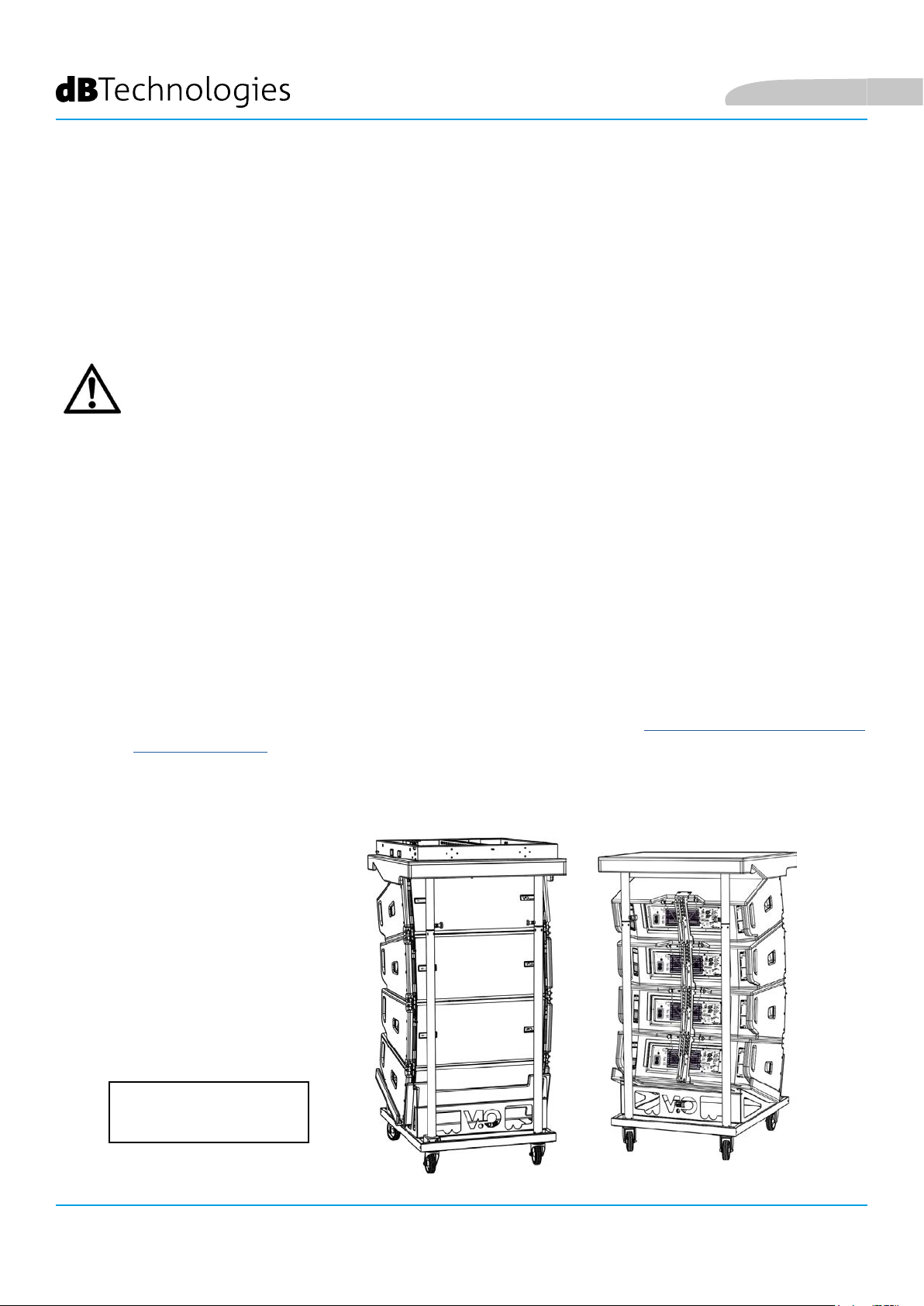
• Trasportare tramite DT-VIOL210 i primi 4 moduli e il y-bar DRK-210 nel punto in cui il line-array sarà
issato. Tenere pronto un secondo carrello (privo di y-bar) con altri 4 moduli per le fasi successive
di montaggio del line-array completo. Per ogni informazione relativa consultare i manuali di questi
accessori.
LE INDICAZIONI DI CABLAGGIO
ILLUSTRATE NELLE FIGURE
SEGUENTI SONO PURAMENTE
INDICATIVE.
VIO-L210 Cod. 420120248 REV. 1.1
23
Page 24
Italiano
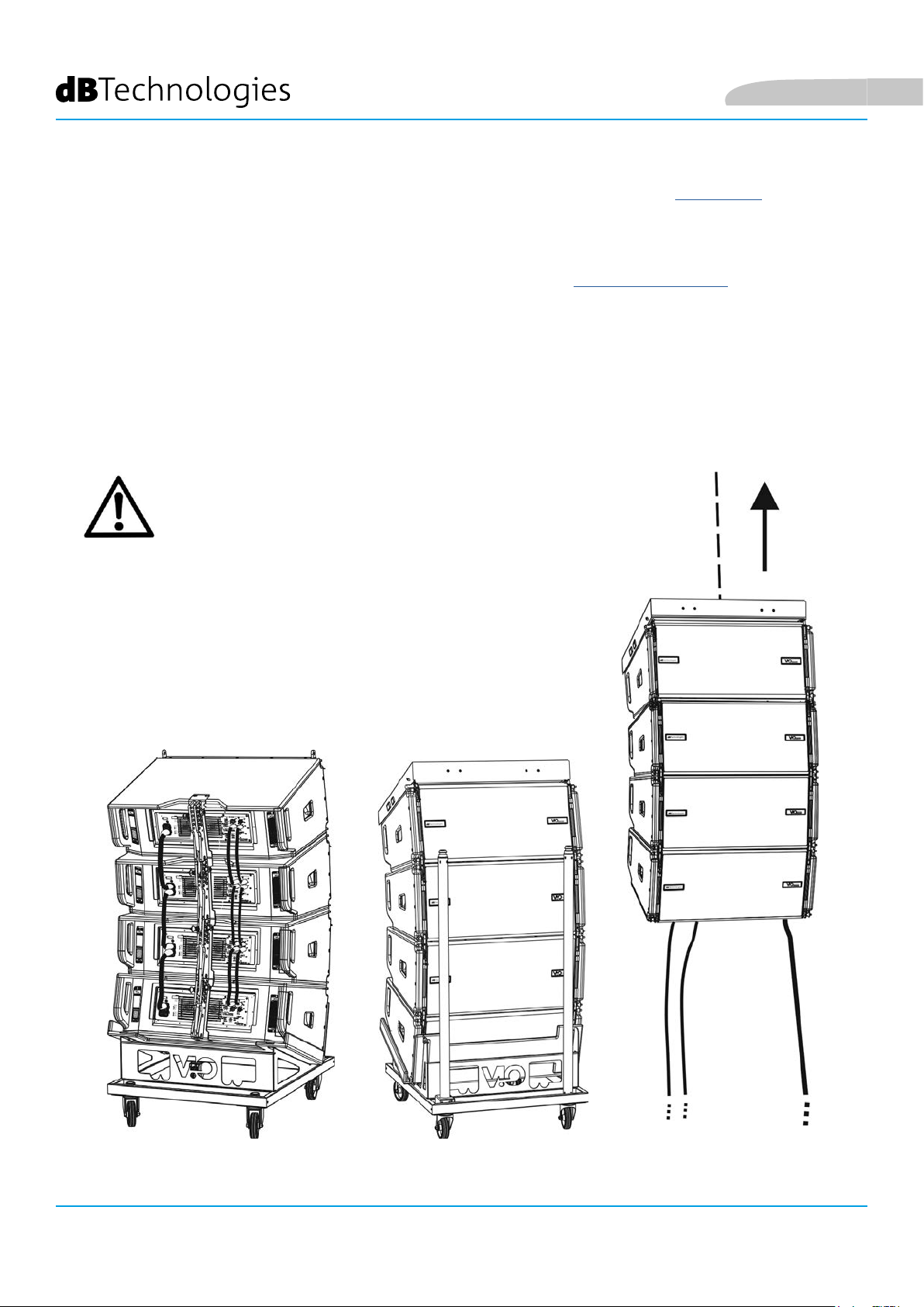
• Assicurare i freni alle ruote di DT-VIOL210.
• Sul retro, inserire i bracci mobili [6] nelle staffe [4] come mostrato nel paragrafo MECCANICA.
• Inserire all’interno dei bracci i pin in corrispondenza degli angoli calcolati in precedenza (per questa
operazione non è necessario sollevare i moduli).
• Effettuare i collegamenti di rilancio audio, RDNet e di alimentazione come da paragra precedenti (per
il numero massimo di rilanci di alimentazione vedere il paragrafo SPECIFICHE TECNICHE).
• Rimuovere il coperchio superiore e i tubolari sul retro di DT-VIOL210.
• Montare sul modulo superiore il y-bar DRK-210 secondo le impostazioni vericate con
DBTECHNOLOGIES COMPOSER.
• Issare tramite uno o due motori ed opportuni mezzi di rigging (non forniti) i 4 moduli ancorati a DRK-
210.
• Togliere i freni alle ruote di DT-VIOL210 e riporre in posizione di riposo il dolly.
ATTENZIONE!
DRK-210 è stato progettato per sospendere no a 25 VIO
L210 (oppure 16 moduli Sub) per un massimo di 750 kg con
un singolo punto di aggancio.
I componenti di sospensione del VIO L210 permettono
di connettere no a 10 moduli (max 300 kg) senza limiti
sull’angolazione del line array. Ogni altra congurazione,
o informazione sui dati del sistema, come la portata
massima e i punti di aggancio, deve essere vericata prima
dell’installazione con il software dBTechnologies Composer
(vedi il paragrafo relativo in questo manuale d’uso). E’
disponibile gratuitamente sul sito www.dbtechnologies.
com. nella sezione DOWNLOADS.
VIO-L210
24
Cod. 420120248 REV. 1.1
Page 25
Italiano
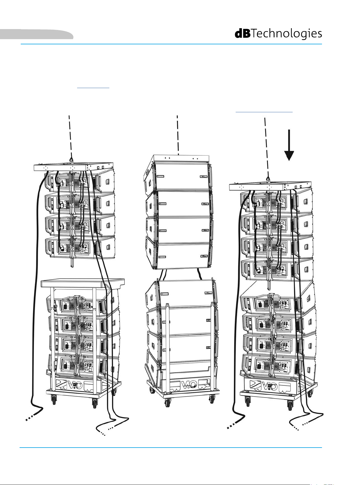
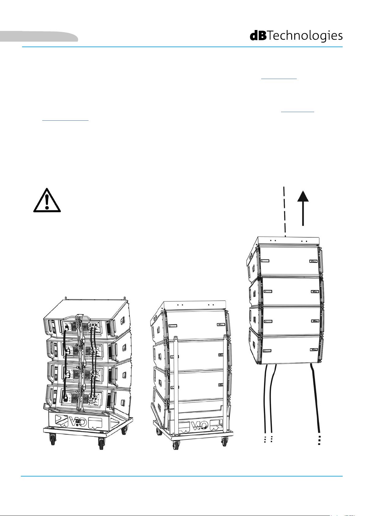
• Portare gli ulteriori 4 moduli con un secondo carrello DT-VIOL210 sotto ai primi 4 attualmente sospesi.
• Porre i freni al carrello, effettuare la regolazione degli angoli come descritto nella fase precedente.
• Rimuovere il coperchio e i tubolari anteriori di DT-VIOL210.
• Far scendere opportunamente i 4 moduli sospesi no ad agganciarli con il metodo descritto nel
paragrafo MECCANICA anteriormente e posteriormente. Prestare la massima attenzione in questa fase
a movimentare il blocco superiore sospeso.
• Completare i collegamenti di rilancio audio, RDNet e di alimentazione come da paragra precedenti
(per il numero massimo di rilanci di alimentazione vedere il paragrafo SPECIFICHE TECNICHE).
•
VIO-L210 Cod. 420120248 REV. 1.1
25
Page 26
Italiano
• Sollevare leggermente il line-array per vericare la correttezza di agganci ed angoli. Eventualmente
vericare con l’inclinometro laser (non fornito) che l’inclinazione del y-bar corrisponda a quella di
progetto. Vericare che tutti i pin siano interamente inseriti e bloccati.
• Togliere i freni al carrello DT-VIOL210, chiuderlo e rimuoverlo.
• Issare con la massima attenzione il line-array così assemblato.
• Porre in essere tutte le ulteriori tecniche di ssaggio necessarie ad un utilizzo sicuro e stabile del line-array,
anche in considerazione di eventuali fenomeni atmosferici a cui può essere sottoposto.
VIO-L210
26
ATTENZIONE!
• Non utilizzare mai le maniglie, le staffe o altri elementi del diffusore per sospendere
direttamente i moduli o il sistema!
• In caso di utilizzo all’aperto è sempre consigliabile ancorare il sistema per prevenire
eventali oscillazioni dovute al vento o agli agenti atmosferici
Cod. 420120248 REV. 1.1
Page 27
Italiano
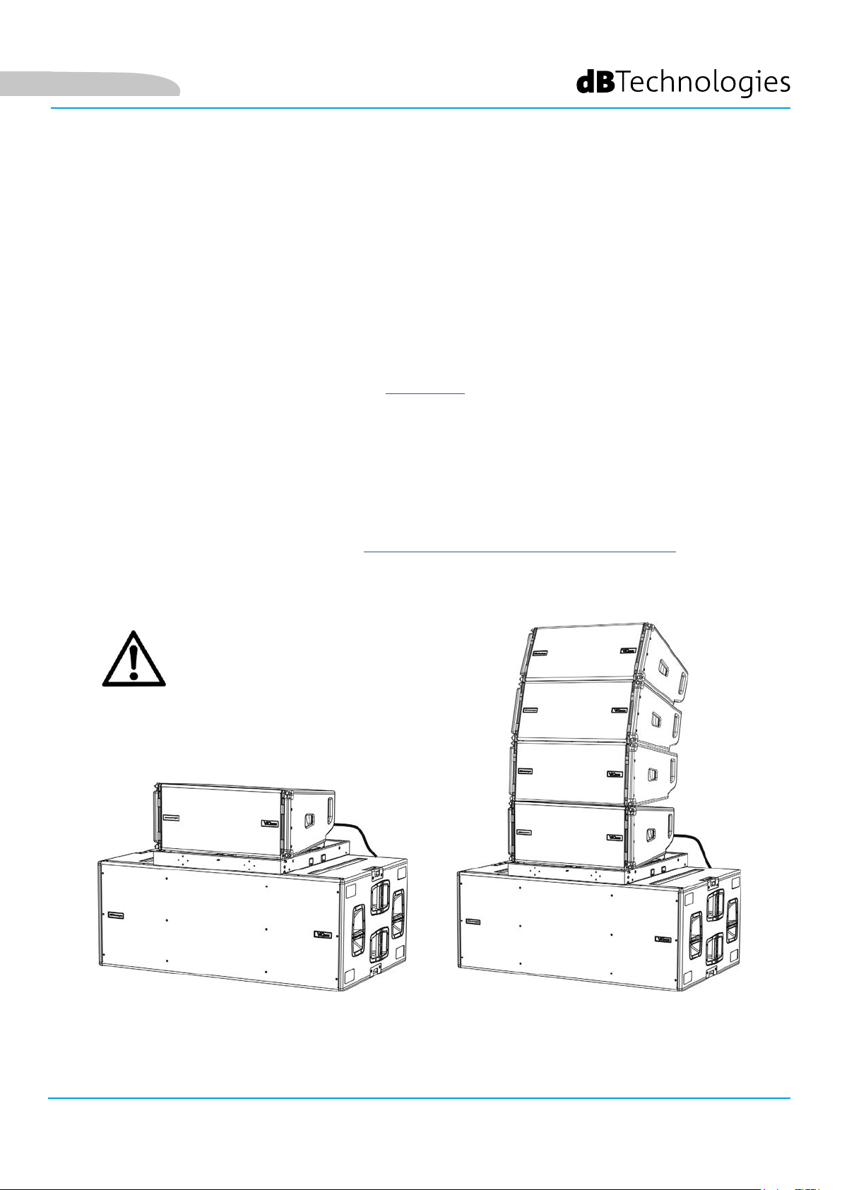
INSTALLAZIONE STACKED (ESEMPIO DI 1 o 4 MODULI SU SUB318)
• E’ possibile montare al massimo 4 moduli in congurazione stacked su y-bar DRK-210.
• Utilizzare DBTECHNOLOGIES COMPOSER per impostare i parametri di progetto, per
motivi di sicurezza.
• Porre su SUB 318 (installato su un piano privo di inclinazione) il y-bar DRK-210. Per i
dettagli relativi a questo accessorio vericare ulteriori dettagli sul manuale completo.
• Aggiungere ad uno ad uno i moduli VIO-L210, con l’angolazione precedentemente
calcolata, come illustrato nel paragrafo MECCANICA.
• Vericare che i parametri locali dei vari moduli siano impostati correttamente
sui singoli pannelli amplicatori. In particolare vericare secondo progetto le
impostazioni di Audio Attenuation, Speaker Coupling e High Frequency Compensation.
In alternativa è possibile modicare in tempo reale anche in un secondo tempo
tutti i parametri da remoto se si effettua una connessione del line-array tramite
rete RDNet (DBTECHNOLOGIES NETWORK). Tuttavia è buona norma che almeno le
impostazioni iniziali di progetto siano replicate sicamente sui moduli VIO-L210 prima
dell’installazione. Vedere la sezione PARAMETRI DSP PRESET E CONTROLLO REMOTO per
ulteriori informazioni.
• Effettuare i collegamenti di rilancio audio, RDNet e di alimentazione come da paragra
precedenti.
ATTENZIONE!
• In caso di supercie di appoggio
che presenti un’inclinazione
anche minima, è obbligatorio
ssare opportunamente con
adeguati mezzi meccanici e/o
cinghie l’installazione.
VIO-L210 Cod. 420120248 REV. 1.1
27
Page 28

6. RISOLUZIONE DEI PROBLEMI
Il modulo non si accende:
1. Vericare la corretta presenza dell’alimentazione a monte dell’impianto.
2. Vericare che l’alimentazione o il collegamento di rilancio di alimentazione sia correttamente inserito.
Il modulo si accende ma non emette nessun suono:
1. Vericare che i collegamenti in ingresso del segnale audio o i rilanci del segnale audio siano
correttamente effettuati.
2. Vericare che Audio Attenuation sia impostato a 0 dB.
3. Vericare che la sorgente audio (mixer) sia collegata correttamente ed attiva.
4. Vericare che, in caso di connessione in rete RDNet e controllo con DBTECHNOLOGIES NETWORK, la
funzione MUTE sia disabilitata.
Italiano
Il modulo emette un suono non pienamente soddisfacente.
1. Rivericare il progetto e le speciche di installazione e congurazione tramite DBTECHNOLOGIES
COMPOSER.
2. Vericare che i parametri di DSP PRESET siano effettivamente replicati sul pannello di controllo del
modulo (soprattutto in caso non si utilizzi il controllo remoto dei moduli).
3. Vericare che, in caso di connessione in rete RDNet e controllo con DBTECHNOLOGIES NETWORK, tutti i
parametri siano impostati correttamente.
VIO-L210
28
Cod. 420120248 REV. 1.1
Page 29

Italiano
7. AGGIORNAMENTO DEL FIRMWARE
È molto importante mantenere aggiornato il rmware del prodotto, per garantirne una piena funzionalità.
Controllare periodicamente il sito http://www.dbtechnologies.com nella sezione “DOWNLOADS”.
1. Scaricare ed installare USB BURNER MANAGER nella sezione “SOFTWARE & CONTROLLER” sul proprio
computer.
2. Scaricare il le .zip dell’ultimo rmware nella sezione “DOWNLOADS” relativa al proprio prodotto.
3. Collegare il prodotto al PC tramite un cavo USB (non fornito) con il connettore del tipo corretto (vedere questo
dettaglio nel capitolo CARATTERISTICHE DELLA SEZIONE DI AMPLIFICAZIONE E DI CONTROLLO).
4. Nella schermata dell’USB BURNER MANAGER, in alto a destra, selezionare “Apertura File”.
5. Selezionare il le del rmware precedentemente scaricato.
6. Seguire le operazioni mostrate a video.
7. Cliccare “AGGIORNA”.
VIO-L210 Cod. 420120248 REV. 1.1
29
Page 30

8. SPECIFICHE TECNICHE
GENERALE
Tipologia: Modulo line-array attivo a 2 vie
DATI ACUSTICI
Risposta in frequenza [- 6 dB]: 67 - 20000 Hz
Risposta in frequenza [± 3 dB]: 78 - 18100 Hz
Max SPL: 134 - 136 dB (frequency/preset dependent)
HF: 1 x 1.4” (Bobina:3”)
Italiano
Tipo di trasduttore HF: Titanio
LF: 2 x 10” (Voice Coil: 2.5)
Tipo di trasduttore LF: Neodimio
Frequenza di crossover: 950 Hz
Guida d’onda per le alte frequenze: Sì
Phase plug: Phase corrector in alluminio
Direttività (HxV): 100° (-6 dB) x10° (singolo modulo)
AMPLIFICATORE
Tipologia: Digipro® G3
Classe di amplicazione: Classe D
Potenza di amplicazione (Picco) 1800 W
Potenza di amplicazione (RMS): 900 W
Alimentazione: Auto-range
Tecnica di rareddamento: Convezione
Temperatura di utilizzo (ambiente): da -15° a +55° [°C]
VIO-L210
30
Cod. 420120248 REV. 1.1
Page 31

Italiano
PROCESSORE
Controller interno: DSP 28/56 bit 48 kHz
Funzioni avanzate: Filtri FIR
Limiter: Peak, RMS, Termico
INTERFACCIA UTENTE
Controlli:
Audio Attenuation, 2 rotary a 8 posizioni (Coupling, Compensation)
Led di segnalazione: Limiter, Signal, Mute/prot, Ready
Led di stato (rete RDNet) Link, Active, Remote Preset Active
INGRESSI ED USCITE
Ingressi e rilanci di alimentazione: PowerCON® In/Link
Ingressi audio: 1x XLR IN bilanciato (isolamento: Floating ADC )
Uscite audio: 1x XLR link OUT bilanciato
Ingressi/uscite RDNet: Data In / Data Out (connettori etherCON®)
USB (aggiornamento del rmware): 1x USB MINI tipo B
SPECIFICHE DI ALIMENTAZIONE (ASSORBIMENTO)
Assorbimento a 1/8 della potenza in
condizioni medie di utilizzo (*):
Assorbimento a 1/3 della potenza in
condizioni massime di utilizzo (**):
Assorbimento con speaker acceso in
assenza di segnale (idle):
1.6 A (220-240V~) - 2.8 A (100-120V~)
2.7 A / 76 W (220-240V~) - 4.7 A / 70 W (100-120V~)
22 W
Corrente di inrush:
21 A
Numero di moduli massimo per
linea di alimentazione (**)
1 + 5 (220-240V~) / 1 + 3 (100-120V~)
[mains input + mains link]:
* NOTA PER L’INSTALLATORE: Valori riferiti a 1/8 della potenza, in condizioni medie di funzionamento (programma musicale con clipping raro
o assente). Si consiglia per qualsiasi tipo di congurazione di considerarli i valori minimi di dimensionamento.
** NOTA PER L’INSTALLATORE: Valori riferiti a 1/3 della potenza, in condizioni pesanti di funzionamento (programma musicale con frequente
clipping e intervento del limiter). E’ consigliabile il dimensionamento secondo questi valori in caso di installazioni e tour professionali.
VIO-L210 Cod. 420120248 REV. 1.1
31
Page 32

SPECIFICHE MECCANICHE
Materiale: cabinet in legno - nitura polliurea nera
Griglia: interamente in metallo - lavorazione CNC
Maniglie integrate (2x lato)
Italiano
Predisposizioni anteriori di
montaggio:
Predisposizioni posteriori di
montaggio:
Stae a scomparsa, punti integrati nel cabinet con pin a sgancio
rapido
Staa graduata e braccio mobile con pin a sgancio rapido
Montaggio own e stacked: Con accessorio y -bar DRK-210
Larghezza: 720 mm (28.35 inch.)
Altezza: 320 mm (9.45 inch.)
Profondità: 520 mm (20.47 inch.)
Peso: 28.6 kg (63 lbs.)
Le caratteristiche, le speciche e l’aspetto dei prodotti sono soggetti a possibili cambiamenti senza previa
comunicazione. dBTechnologies si riserva il diritto di apportare cambiamenti o miglioramenti nel design o nelle
lavorazioni senza assumersi l’obbligo di cambiare o migliorare anche i prodotti precedentemente realizzati.
VIO-L210
32
A.E.B. Industriale Srl
Via Brodolini, 8
Località Crespellano
40053 VALSAMOGGIA
BOLOGNA (ITALIA)
Tel +39 051 969870
Fax +39 051 969725
www.dbtechnologies.com
info@dbtechnologies-aeb.com
Cod. 420120248 REV. 1.1
Page 33

English
TABLE OF CONTENTS
1. GENERAL INFORMATION .................................................................................................... 34
WELCOME! ....................................................................................................................... 34
INTRODUCTORY OVERVIEW ............................................................................................ 34
USER REFERENCES ............................................................................................................ 34
MECHANICAL AND ACOUSTIC CHARACTERISTICS .......................................................... 35
SIZE AND WEIGHT ................................................................................................................................... 35
ACOUSTIC CHARACTERISTICS .................................................................................................................. 35
MECHANICS ............................................................................................................................................. 36
ACCESSORIES ........................................................................................................................................... 39
AMPLIFICATION AND CONTROL SECTION CHARACTERISTICS ....................................... 40
INPUT, OUTPUT AND CONTROL SECTION .............................................................................................. 41
POWER SECTION...................................................................................................................................... 42
2. DBTECHNOLOGIES COMPOSER .......................................................................................... 43
3. DSP PRESET PARAMETERS AND REMOTE CONTROL ....................................................... 47
4. CONNECTIONS ...................................................................................................................... 49
CONNECTING AND RE-LAUNCHING THE POWER SUPPLY ..................................................................... 49
CONNECTING AND RE-LAUNCHING THE AUDIO SIGNAL AND RDNET ................................................. 50
5. INSTALLATION AND CONFIGURATION .............................................................................. 52
PACKAGE CONTENT .......................................................................................................... 52
FLOWN INSTALLATION (EXAMPLE OF 1 ARRAY WITH 8 MODULES) ............................. 52
STACKED INSTALLATION (EXAMPLE OF 1 OR 4 MODULES ON SUB318) ....................... 56
6. TROUBLESHOOTING ............................................................................................................ 57
7. FIRMWARE UPDATE ............................................................................................................. 58
8. TECHNICAL SPECIFICATIONS .............................................................................................. 59
GENERAL .................................................................................................................................................. 59
ACOUSTIC DATA ....................................................................................................................................... 59
AMPLIFIER ................................................................................................................................................ 59
PROCESSOR .............................................................................................................................................. 60
USER INTERFACE ...................................................................................................................................... 60
INPUTS AND OUTPUTS ............................................................................................................................ 60
POWER SPECIFICATIONS (ABSORPTION) ................................................................................................ 60
MECHANICAL SPECIFICATIONS ............................................................................................................... 61
VIO-L210 Cod. 420120248 REV. 1.1
33
Page 34

English
1. GENERAL INFORMATION
WELCOME!
Thank you for purchasing a product designed and developed in Italy by dBTechnologies! This powerful and
quick to assembly active line array module is the result of years of experience in the eld of sound systems.
It implements optimized solutions in the acoustic and electronic elds as well as in the choice of materials.
INTRODUCTORY OVERVIEW
The active 2-way line array module VIO-L210 starts a new era in the eld of sound systems for medium to large
live indoor and outdoor applications. The VIO family combines technical innovation and optimized design in a
superbly sounding system, packed into a compact mechanical solution that is quick and easy to install. The key
features are:
• acoustic design based on a waveguide and 2 optimized phase plugs, which level out the frequency
response for accurate audio coverage
• wooden cabinet with a polyurea nish, to increase surface durability
• a 3-point integrated rigging system for quick assembly/disassembly
• a powerful (900 W RMS) and silent amplier, which does not require ventilation and allows reaching
a SPL peak of 136 dB (at 1 m)
• control entrusted to a powerful 56-bit DSP
• Floating ADC technology, developed to provide the audio input with perfect isolation from
interferences, noise or humming
• power, audio and network re-launches for optimized cabling
• RDNet control, predictive and remote management software (DBTECHNOLOGIES COMPOSER, EASE,
EASE FOCUS 3, DBTECHNOLOGIES NETWORK)
USER REFERENCES
In order to best use your VIO speaker, we recommend the following:
• read the quick start user manual included in the package as well as this user manual in its entirety and
keep it for the entire lifetime of the product
• register the product on the website http://www.dbtechnologies.com under the “SUPPORT” section
• keep proof of purchase and WARRANTY (User Manual “Section 2”)
VIO-L210
34
Cod. 420120248 REV. 1.1
Page 35
English
MECHANICAL AND ACOUSTIC CHARACTERISTICS
SIZE AND WEIGHT
The VIO Series has been designed with particular attention to the optimization of weight and size.
The wooden cabinet, coated in polyurea, weighs 63 lbs (28.6 kg).
The measurements are: 28.35 in (720 mm) (L), 12.3 in (312 mm) (H), 20.5 in (520 mm) (W).
ACOUSTIC CHARACTERISTICS
The acoustic optimization begins with the careful choice
of the wooden cabinet's materials, shape and geometry.
There are several devices within the module that ensure
accuracy in a very wide range of frequencies.
In particular, the two 10" high quality woofers with
neodymium magnets and a 3" titanium compression driver
(1/4" output) are optimized thanks to:
1) two aluminum PHASE PLUGS (with diamond holes), which
provide closer low-frequency emission points by increasing
off-axis listening consistency.
2) sound insulation foam, used to remove internal reections
of the phase plugs.
3) a waveguide designed to control vertical directivity in high
frequencies and obtain a cylindrical wave front.
These details ensure a perfect match between the modules,
thus allowing optimal frequency response for both long
distance and off-axis listening.
VIO-L210 Cod. 420120248 REV. 1.1
35
Page 36
MECHANICS
The module's ergonomics and the quick assembly in line arrays are guaranteed by:
English
FRONT SIDE
1) Lower anchorage system for the connection of other modules or the DRK-210 y-bar (in a stacked
conguration).
2) Retractable brackets for anchoring to a higher module (or to the DRK-210 y-bar in a own conguration).
3) Pins for fastening the retractable brackets in open/closed position [2].
REAR SIDE
4) Central bracket. Equipped with a graduated label, allows selecting the angle of the line array module.
1° steps are possible (range: 0-10°).
5) Pins for fastening the angle of inclination: only one pin is needed in the own conguration, and 2 in
the stacked one. For that purpose, refer to the gures on page 9.
6) A movable arm with a loop. Inserted into the bracket [4], it mechanically xes the chosen angle with
the pins [5].
RIGHT AND LEFT SIDE
7) Handle balanced according to the weight of the cabinet.
8) Back handle for easier lifting the rear of the module, when the front side is xed.
The VIO-L210 modules are also equipped with 2 rain
covers on the rear side, in order to protect the
amplier from water and allow operation even in
critical weather conditions. They will be no longer
shown in the following drawings, for simplicity.
For further information regarding the y-bar (see the
ACCESSORIES section), please refer to the relevant
manual.
VIO-L210
36
Cod. 420120248 REV. 1.1
Page 37
English
The assembly of the 2 modules A and B requires a few easy steps:
• On module A, remove the pins [3], raise the retractable brackets [2] and fasten them to the new position
using the pins [3].
• Remove the pins [1] from module B, place it on top of module A, inserting the brackets [2] as shown. Then
fasten the front side of the two modules using the pins [1] of module B.
• On the back, remove the pins [5] from the rear brackets [4]. Then insert the movable arm [6] of module
B into the bracket [4] of module A. The next page shows in detail the fastening of the angle on the rear
between the two modules.
VIO-L210 Cod. 420120248 REV. 1.1
37
Page 38
English
The example shows the case in which you want to set a 3° angle between the 2 modules.
Before carrying out any other operation, make sure that once the movable arm is inserted [6], the hole of the
chosen angle is contained inside the loop as shown.
• FLOWN CASE: insert only one pin in the hole on the chosen angle. The second pin can be housed in the
“PIN HOLDER” hole. Note that this type of conguration during the assembly allows changing the chosen
angle simply by moving the respective pin (with the movable arm inserted).
• STACKED CASE: once the pin [5] is inserted into the hole of the chosen angle, lift module B as far as the
movable arm [6] allows. At this point, insert the second pin into the “ANGLE LOCK” position and release
module B. This way, module B is completely blocked by the two pins on the rear.
After assembly is completed, always make sure that all the pins have been completely inserted and are well
locked.
VIO-L210
Cod. 420120248 REV. 1.1
38
Page 39

English
ACCESSORIES
For quick installation, the following optional accessories can be purchased:
• DRK-210, y-bar for the own and stacked use of the line arrays of VIO-L210 modules.
• DT-VIOL210, a cart to transport up to 4 VIO-L210 modules. Thanks to this accessory, it is possible
to mount on top of the lid, only for transport, 1 DRK-210 y-bar.
DRK-210
WARNING!
• Only use accessories and congurations described in this manual and operate according to the
instructions in the manuals provided with the accessories.
• DRK-210 was designed for the suspension of up to 25 VIO L210 (or 16 Sub modules) for a maximum
of 1653 lbs (750 kg) with a single coupling point.
The VIO L210 suspension components allow you to connect up to 10 modules (661 lbs (300 kg) max)
without limiting the angulation of the line array. Any other conguration or information regarding
the system's data, such as the maximum capacity and attachment points, must be veried prior to
installation using the dBTechnologies Composer software (see the relevant paragraph in this user
manual). It is available for free on the website www.dbtechnologies.com under the DOWNLOAD
section.
For any further information, please refer to the relevant manuals.
For all updates on accessories, please visit www.dbtechnologies.com
DT-VIOL210
VIO-L210 Cod. 420120248 REV. 1.1
39
Page 40
AMPLIFICATION AND CONTROL SECTION CHARACTERISTICS
The class D digital amplier is the heart of the VIO-L210
modules.
It allows delivering up to 900 W RMS, silently and efciently,
without ventilation. The system is controlled by a powerful DSP
that makes it possible to congure the line array in any usage
context, instantly and quickly.
Thanks to the ability of network connection with RDNet,
the panel parameters can be controlled remotely, due to
“dBTechnologies NETWORK” software (see the paragraph
DSP PRESET PARAMETERS AND REMOTE CONTROL).
The DIGIPRO G3 panel features:
• Input, Output and Control section
• Power Supply Section
English
INPUT, OUTPUT
SECTION
AND CONTROL
WARNING!
• Do not obstruct the rear heat sinks of the
amplier. If the module heats up excessively,
the audio volume is gradually reduced until
VIO-L210 is thermally stabilised. The audio
is automatically restored when the normal
operating temperature is reached.
• Do not try in any way to open the amplier.
• In the event of malfunction, immediately
turn off the power by disconnecting the
module from the power grid and contact
an authorized technician.
• It is preferable to use high quality cables
equipped with original Neutrik® connectors.
Check their integrity regularly.
• The speaker is supplied with a mounted fuse
for operation within the 220-240 V range.
If you need to operate in the 100-120 V voltage
range:
1. Disconnect all connections,
including the power supply.
2. Wait 5 minutes.
3. Replace the fuse with the one
provided in the package for the 100120 V range.
SECTION
POWER SUPPLY
VIO-L210
40
WARNING!
• Never remove the product's front protection mesh.
In order to prevent electric shock hazard, in the event of accidental damage or replacement of
the protection mesh (which must be carried out by a service center), disconnect the power supply
immediately.
Do not connect to the power supply while the mesh has been removed.
Cod. 420120248 REV. 1.1
Page 41

English
INPUT, OUTPUT AND CONTROL SECTION
1. AUDIO INPUT AND RE-LAUNCH (“Balanced audio”)
Input and output compatible with balanced XLR cables.
In particular, the “Input” is used for connection with the audio signal originating from the mixer or from another
loudspeaker, the “Output Link” is used for the re-launching of the signal to the other modules of the line array,
in a daisy-chain conguration.
2. AUDIO ATTENUATION
Allows adjusting the attenuation of the module using the input volume.
Put to 0 dB before starting the assembly of the line array.
3. INPUT AND RE-LAUNCHING OF THE RDNet NETWORK CONNECTION
Section compatible with network cables equipped with etherCON/RJ45-type connectors.
In particular, “Data in” should be connected to devices such as RDNet Control 2 or Control 8; “Data Out” can
be used for the re-launching of the network to other modules of the line array in a daisy-chain conguration.
4. DSP PRESET
Rotary for the acoustic setup of the line array.
It is appropriate to use these controls (or the same parameters remotely via the RDNet connection) in order
to optimize the acoustic behavior depending on the number of modules and how they are orientated. Further
details on the use of “SPEAKER COUPLING” and “HIGH FREQUENCY COMPENSATION” can be found in the
“DSP PRESET PARAMETERS AND REMOTE CONTROL” section.
5. STATUS LEDs
LEDs for the operation of the module. A table on the next page summarizes the meaning of the different LEDs.
6. CONTROL LEDs
LEDs for the network (RDNet) operation of the module.
In particular, if “Link” is on, it indicates that the RDNet network is active and it has recognized the device.
If “Active” is ashing, it indicates that there is data trafc. “Remote Active Preset” indicates that all local controls
on the amplier's panel are by-passed by the RDNet remote control.
7. USB DATA SERVICE
A mini-USB B port, to be used only for the rmware update of the product. See the “FIRMWARE UPDATE” section
for further information.
VIO-L210 Cod. 420120248 REV. 1.1
41
Page 42

English
LED TYPE TURNING THE
SPEAKER ON
NORMAL
OPERATION
GENERIC
WARNING
SPEAKER SHUTS
DOWN DUE TO
MALFUNCTION
LIMITER OFF TURNED OFF,
TURNS ON ONLY
IN THE EVENT OF
INTERVENTION
SIGNAL
MUTE/
PROT
READY OFF PERMANENTLY ON PERMANENTLY ON OFF
OFF FLASHING IN THE
PRESENCE OF A
SIGNAL
TURNED ON FOR
A FEW SECONDS
OFF TEMPORARY
Table of the status LED signals
TEMPORARY
FLASHING
NORMAL SIGNAL
OF INPUT AUDIO
FLASHING
CONTINUOUS CYCLIC
FLASHING
OFF
PERMANENTLY ON
POWER SECTION
8. “MAINS INPUT” POWER CONNECTION
Compatible with the powerCON TRUE1® connector, the power supply is equipped with the auto-range function.
Once the appropriate range has been dened, if necessary by replacing the fuse, it automatically recognizes the
voltage within the interval [100-120V~] or [220-240V~].
9. “MAINS LINK” POWER RE-LAUNCH
Compatible with a powerCON TRUE1® type connector for the re-launching of the power to other modules.
To nd the maximum number of modules that can be connected in a re-launched system, see the TECHNICAL
SPECIFICATIONS section.
10. NETWORK FUSE
Housing for the network fuse.
VIO-L210
Cod. 420120248 REV. 1.1
42
Page 43

English
2. DBTECHNOLOGIES COMPOSER
dBTechnologies Composer software, available for free download from www.dbtechnologies.com, is a tool
for the proper designing of the audio systems, recommended for the entire VIO series.
It offers a solution for the spaces to sonorize, indicating the angle of the line array modules in order
to achieve the desired coverage and the preset to use.
Despite being a predictive tool, it allows a series of manual adjustments in order to rene the conguration
according to any sound eld measurements or to specic requirements.
Lastly, it is an effective tool for assessing the safety of the installation. In fact, thanks to the simulation of
the y-bar's static behavior and an indication of the mechanical forces at play, it allows verifying how many
modules should be installed before reaching an overload condition.
The main sections of the dBTechnologies Composer are:
• COMPOSER - general view that allows entering the project's initial data
• LAs PREDICT - with safety simulation, conguration and testing of line arrays
• SUBs PREDICT - with safety simulation, conguration and testing of subwoofers
This chapter describes some of the software's details relating to installation and safety, in particular for the
FLOWN conguration of the VIOL210 line array.
VIO-L210 Cod. 420120248 REV. 1.1
43
Page 44

English
The LAs PREDICT section contains all the information necessary for the proper conguration, own or stack,
of a VIO system. To access it, you need to rst enter the project's data, included in the Composer section.
The System Data sub-page provides the following suggestions: the angulation of the various modules,
various parameters relating to the “DSP preset” section and the angulation of the DRK-210 y-bar. This last
angulation can be detected on the eld with the use of a laser inclinometer, not included, the assembly of
which is illustrated in the DRK-210 manual.
VIO-L210
44
Cod. 420120248 REV. 1.1
Page 45

English
In the Safety Data section, you can nd a simulation of the
own system's centre of gravity with DRK-210.
In particular, the user can choose between EUROCODE 3
or BGV-C1 references.
The related results are shown in green, if safe, and in red,
if the maximum permissible load for the chosen angle is
being exceeded (and which is therefore forbidden to use).
VIO-L210 Cod. 420120248 REV. 1.1
45
Page 46

In the event that only one engine is being used in a own
conguration, “SINGLE” indicates the position of the
single hook to use on DRK-210 (which requires graduated
positions described by a label placed on the y-bar).
In addition, there is a “FRONT” or “REAR” direction for
directing the hook for the engine.
In the case of “FRONT”, the reference (shown in the gure
below and shown as LOAD ADAPTOR REFERENCE SIDE),
should be placed toward the front of the line array, in the
case of “REAR”, it should be directed toward the rear of
the line array.
If instead two engines are used, the hooks should always
be placed at the ends of the y-bar (in this case, the
direction of the placement is irrelevant).
English
For any other information on the dBTechnologies
Composer software, see the relevant manual, available
for free download from: www.dbtechnologies.com.
VIO-L210
46
Cod. 420120248 REV. 1.1
Page 47

English
3. DSP PRESET PARAMETERS AND REMOTE CONTROL
Using a line array entails a series of advantages in various contexts, in particular:
• homogeneous SPL along the front vector of the speakers, an effect that is particularly appreciated
at medium to long distances
• directing acoustic behavior, which allows to precisely focus the sound on the audience, avoiding
unnecessary losses in areas where acoustic coverage is not required
Possible optimization of the line array takes into account the behavior of the system according to the
frequency:
• increasing the distance from the line array increases the air attenuation. This especially affects high
frequencies
• increasing the angulation between elements of the line array decreases mid-frequency phase coupling
• as the number of modules of the line array increases, low frequencies will add together in an
acoustically coherent fashion
The acoustic conguration in a line array of the VIO L210 modules can be optimized, thanks to the control
functions managed by DSP. The user interface is simple and straightforward: it employs two rotaries of the
“DSP Preset” (4) section and refers to the explanatory label placed on the side of the amplier:
• Place the “SPEAKER COUPLING” rotary depending on the
number of modules used in the line array. This rotary acts
on the low frequencies and should be set to the position:
• A - from 2 to 6 speakers
• B - from 7 to 8 speakers
• C - from 9 to 10 speakers
• D - from 11 to 12 speakers
• E - from 13 to 14 speakers
• F - more than 15
• G - to enhance the low frequencies (front ll
or stand-alone use)
VIO-L210 Cod. 420120248 REV. 1.1
47
Page 48

English
• Place the “HIGH FREQUENCY COMPENSATION” rotary depending
on the type of installation and angulation set in the line array.
This rotary acts on the mid-high frequencies and should be set
to the position:
• 1 - FLAT (no emphasis on any particular frequency range)
• 2 - front ll with the audience at a distance of 0 to 5 m (16 feet)
• 3 - with the audience at a distance of 6-20 m (17-66 feet)
• 4 - with the audience at a distance of 21-30 m (67-98 feet)
• 5 - with the audience at a distance of 31-40 m (99-131 feet)
• 6 - with the audience at a distance of 41-50 m (132-164 feet)
• 7 - with the audience at a distance of 51-60 m (165-197 feet)
• 8 - with the audience at a distance of 61 m (198 feet)
• All these parameters can be adjusted with the remote control, once the RDNet connections have
been properly made, using the free DBTECHNOLOGIES NETWORK software (free to download from
www.dBTechnologies.com in the DOWNLOADS section). When using the remote control, the local
controls on the panels of the VIO-L210 modules are by-passed. Using this software, you can control
a larger number of parameters (for more information, please refer to the full DBTECHNOLOGIES
NETWORK manual).
VIO-L210
48
Last settings stored on VIOL210 (using DBTECHNOLOGIES NETWORK software), can be
recalled later on the speaker, without RDNet remote control. To do this, turn the rotary
SPEAKER COUPLING on Service/User position.
Cod. 420120248 REV. 1.1
Page 49
English
4. CONNECTIONS
CONNECTING AND RE-LAUNCHING THE POWER SUPPLY
A
B
C
MODULE 1
MODULE 2
The illustration above shows a generic connection, in which module 1
is under module 2. For this purpose, use cables with powerCON TRUE1® connectors (not provided).
• Connect the power supply of module 1 AUTO-RANGE MAINS INPUT (A).
• Re-launch the power supply from module 1 to module 2 by connecting the MAINS LINK output (B)
of module 1 to the AUTO-RANGE MAINS INPUT (C) of module 2.
• Repeat this operation until you have connected the maximum permitted number of line array
modules (see the chapter TECHNICAL SPECIFICATIONS).
WARNING!
• The cables must be properly sized and the system's design, installation and
testing should be performed by qualied personnel only. AEB industriale declines
any responsibility in case of cables that are non-compliant, uncertied and
incompatible with the proper layout of the system and the regulations in force
for the country of use.
VIO-L210 Cod. 420120248 REV. 1.1
49
Page 50

CONNECTING AND RE-LAUNCHING THE AUDIO SIGNAL AND RDNET
English
A
MODULE 1
B
MODULE 2
C
The illustration above shows a generic connection, in which module 1 is above module 2, this time
showing audio and network connections. For this purpose, use non-provided cables, with XLR (audio)
and etherCON/RJ45 (network) connectors. For further information on the types of cables available,
see also the image on the next page.
A
B
C
• For the audio connection, connect the cable originating from MIXER/LINE to the BALANCED
AUDIO INPUT (A) of module 1 of the line array. Re-launch the signal between the rst and
the second module. For this purpose, connect the output BALANCED AUDIO OUTPUT/LINK (B)
of module 1 to the BALANCED AUDIO INPUT (C) of module 2.
• Repeat the operation between the second and the third module and so on, until all modules
of the line array are connected.
• For the network connection, connect the DATA IN (A) connector of module B to the remote
control (RDNet CONTROL 2 or RDNet CONTROL 8). Re-launch the signal by connecting DATA
OUT (B) of module 1 to DATA IN (C) of module 2.
• Repeat the operation between the second and the third module and so on, until all modules
of the line array are connected.
WARNING!
• Replace any damaged cables to prevent malfunctions and poor sound quality.
VIO-L210
50
Cod. 420120248 REV. 1.1
Page 51
English
VIO-L210 Cod. 420120248 REV. 1.1
51
Page 52
5. INSTALLATION AND CONFIGURATION
PACKAGE CONTENT
Check that the package content of the VIO-L210 module is complete. The package contains:
• VIO-L210 Module
• fuse for operation in the 110-120V~ range (see the AMPLIFICATION AND CONTROL SECTION
CHARACTERISTICS section for more information)
• quick start and warranty documentation
WARNING!
The product and accessories must be handled by experienced personnel only! Make sure that the installation
is positioned in a stable and safe manner in order to avoid hazardous conditions for people, animals and/or
objects. The user is required to follow regulations and mandatory laws on safety of the country in which the
product is used. For safe use, regularly check the operation of all parts and integrity before use.
Design, calculations, installation, testing and maintenance of suspended systems or professional audio stacks
must be performed by authorized personnel only. AEB Industriale is not responsible for improper installations,
non-compliant with safety requirements.
English
FLOWN INSTALLATION (EXAMPLE OF 1 ARRAY WITH 8 MODULES)
• Use the DBTECHNOLOGIES COMPOSER to set the project parameters.
• Verify that the local parameters of different modules are properly set on the individual amplier
panels. In particular, verify according to the project: Audio Attenuation, Speaker Coupling and High
Frequency Compensation settings. Alternatively, you can remotely and in real time change all the
parameters, if the line array is connected via the RDNet network (DBTECHNOLOGIES NETWORK). In this
case it is also good practice to physically replicate the initial settings of the project on the VIO-L210
modules before the installation. For further information see the section DSP PRESET PARAMETERS AND
REMOTE CONTROL.
• Transport, through DT-VIOL210, the rst 4 modules and the DRK-210 y-bar to the spot in which
the line array will be lifted. Have a second cart (without a y-bar) ready with other 4 modules for
the following assembly stages of the complete line array. For any relevant information, refer to the
manuals of these accessories.
VIO-L210
52
THE CONNECTIONS SUGGESTED
IN THE FOLLOWING PICTURES
ARE FOR INFORMATION ONLY.
Cod. 420120248 REV. 1.1
Page 53
English
• Fix the brakes on the DT-VIOL210 wheels.
• On the back, insert the movable arms [6] into the brackets [4] as shown in the MECHANICS paragraph.
• Insert the pins corresponding to the previously calculated angles inside the arms (for this operation,
you do not need to lift the modules).
• Perform audio, RDNet and power supply re-launch connections as described in the previous paragraphs.
To nd the maximum number of power connections in a re-launched system, see the TECHNICAL
SPECIFICATIONS section.
• Remove the top cover and the tubes on the back of DT-VIOL210.
• Mount the DRK-210 y-bar on the top module according to the settings veried with the
DBTECHNOLOGIES COMPOSER.
• Lift the 4 modules anchored to DRK-210 using one or two engines and the appropriate means for
rigging (not provided).
• Remove the brakes from the DT-VIOL210 wheels and put the dolly back in the rest position.
WARNING!
DRK-210 was designed for the suspension of up to 25 VIO
L210 (or 16 Sub modules) for a maximum of 1653 lbs (750 kg)
with a single coupling point.
The VIO L210 suspension components allow you to
connect up to 10 modules (661 lbs (300 kg) max) without
limiting the angulation of the line array. Any other
conguration or information regarding the system's data,
such as the maximum capacity and attachment points, must
be veried prior to the installation using the dBTechnologies
Composer software (see the relevant paragraph in this
user manual). It is available for free on the website
www.dbtechnologies.com under the DOWNLOADS section.
VIO-L210 Cod. 420120248 REV. 1.1
53
Page 54
English
• Bring the additional 4 modules with a second DT-VIOL210 cart under the rst 4, currently suspended.
• Apply brakes to the cart and adjust the angles as described in the previous step.
• Remove the cover and the tubes on the front of DT-VIOL210.
• Properly lower the 4 suspended modules and hook them as described in the MECHANICS paragraph for
both front and rear. Pay careful attention to this step when moving the upper suspended block.
• Complete audio, RDNet and power supply re-launch connections as described in the previous
paragraphs. To nd the maximum number of power connections in a re-launched system, see the
TECHNICAL SPECIFICATIONS section.
VIO-L210
54
Cod. 420120248 REV. 1.1
Page 55

English
• Slightly lift the line array to verify the correctness of hooks and angles. If necessary, check with a laser
inclinometer (not provided) that the inclination of the y-bar corresponds to the one in the project. Check
that all the pins have been fully inserted and are locked.
• Remove the brakes from the DT-VIOL210 cart, close it and remove it.
• Lift the assembled line array with maximum care.
• Implement any other fastening technique necessary for the safe and stable use of the line array, also
considering any atmospheric phenomena it may be exposed to.
WARNING!
• Never use the handles, the brackets or other elements of the speaker to directly
suspend the modules or the system!
• In case of outdoor use, it is recommended to anchor the system to prevent any
oscillations due to wind or weather conditions.
VIO-L210 Cod. 420120248 REV. 1.1
55
Page 56
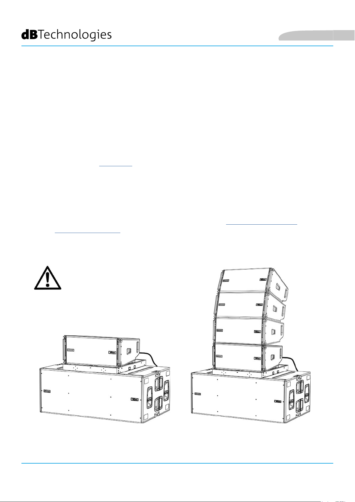
STACKED INSTALLATION (EXAMPLE OF 1 OR 4 MODULES ON SUB318)
• It is possible to install a maximum of 4 modules in a stacked conguration on the
DRK-210 y-bar, for safety reason.
• Use the DBTECHNOLOGIES COMPOSER to set the project parameters.
• Place the DRK-210 y-bar on SUB 318 (installed on a level with no inclination). For more
information about this accessory, see further details in the full manual.
• Add the VIO-L210 modules one by one, with the previously calculated angulation,
as shown in the MECHANICS paragraph.
• Verify that the local parameters of different modules are properly set on the individual
amplier panels. In particular, verify according to the project: Audio Attenuation,
Speaker Coupling and High Frequency Compensation settings. Alternatively, you can
also remotely and in real time change all parameters later, if the line array is connected
via the RDNet network (DBTECHNOLOGIES NETWORK). However, it is good practice to
physically replicate at least the initial settings of the project on the VIO-L210 modules
before the installation. For further information see the section DSP PRESET PARAMETERS
AND REMOTE CONTROL.
• Perform audio, RDNet and power supply re-launch connections as described in the
previous paragraphs.
English
WARNING!
• If the support surface presents
even the slightest inclination, it is
necessary to properly fasten using
the appropriate mechanical means
and/or installation straps.
VIO-L210
56
Cod. 420120248 REV. 1.1
Page 57

English
6. TROUBLESHOOTING
The module does not turn on:
1. Check the correct power supply upstream of the system.
2. Check that the power supply or the re-launch connection of the power supply is properly inserted.
The module turns on but does not make any sound:
1. Check that the audio signal input connections or the audio signal re-launches are properly carried out.
2. Check that the Audio Attenuation is set to 0 dB.
3. Check that the audio source (mixer) is properly connected and active.
4. In case of RDNet network connection and control with the DBTECHNOLOGIES NETWORK, verify that the
MUTE function is disabled.
The sound is not completely satisfactory.
1. Re-check the project, the installation and conguration specications using the DBTECHNOLOGIES
COMPOSER.
2. Verify that the DSP PRESET parameters are actually replicated on the control panel of the module
(especially if the remote control of the module is not used).
3. Check that all the parameters are properly set, in case of RDNet network connection and control with
the DBTECHNOLOGIES NETWORK.
VIO-L210 Cod. 420120248 REV. 1.1
57
Page 58

English
7. FIRMWARE UPDATE
IT IS very important to keep the product rmware up to date, to ensure full functionality. Regularly check the
website http://www.dbtechnologies.com under the “DOWNLOADS” section.
1. Download and install on your PC the USB BURNER MANAGER under the “SOFTWARE & CONTROLLER” section.
2. Download the .zip le of the latest rmware in the “DOWNLOADS” section of your product.
3. Connect the product to the PC using a USB cable (not provided) with a suitable connector type (see this detail
in the AMPLIFICATION AND CONTROL SECTION CHARACTERISTICS) chapter.
4. On the USB BURNER MANAGER screen, at the top right of the screen, select “Open File”.
5. Select the le containing the previously downloaded rmware.
6. Follow the operations shown on the screen.
7. Click “UPDATE”.
VIO-L210
58
Cod. 420120248 REV. 1.1
Page 59

English
8. TECHNICAL SPECIFICATIONS
GENERAL
Type: Active 2-way line array module
ACOUSTIC DATA
Frequency response [- 6 dB]: 67 - 20,000 Hz
Frequency response [± 3 dB]: 78 - 18,100 Hz
Max SPL: 134 - 136 dB (frequency/preset dependent)
HF: 1 x 1.4” (Coil:3”)
Type of HF transducer: Titanium
LF: 2 x 10” (Voice Coil: 2.5)
Type of LF transducer: Neodymium
Crossover frequency: 950 Hz
Waveguide for high frequencies: Yes
Phase plug: Aluminum phase corrector
Directivity (HxV): 100° (-6 dB) x10° (single module)
AMPLIFIER
Type: Digipro® G3
Amplication class: Class D
Amplication power (Peak) 1800 W
Amplication power (RMS): 900 W
Power supply: Auto-range
Cooling technique: Convection
Operating temperature range
(ambient):
VIO-L210 Cod. 420120248 REV. 1.1
from -15° to + 55° [°C]
59
Page 60

PROCESSOR
Internal control: DSP 28/56 bit 48 kHz
Advanced functions: FIR Filters
Limiter: Peak, RMS, ermal
USER INTERFACE
English
Controls:
Audio Attenuation, 2 rotaries with 8 positions (Coupling, Compensation)
LED indicators: Limiter, Signal, Mute/prot, Ready
Status LEDs (RDNet network) Link, Active, Remote Preset Active
INPUTS AND OUTPUTS
Power supply inputs and re-launches: PowerCON® In/Link
Audio outputs: 1x XLR link OUT balanced
Audio inputs: 1x XLR IN balanced (insulation: Floating ADC)
RDNet inputs/outputs: Data In / Data Out (etherCON® connectors)
USB (rmware update): 1x MINI USB type B
POWER SPECIFICATIONS (ABSORPTION)
Absorption at 1/8 of the power in
average conditions of use (*):
Absorption at 1/3 of the power in
maximum conditions of use (**):
Absorption with the speaker turned
on with no signal (idle):
2.7 A / 76 W (220-240V~) - 4.7 A / 70 W (100-120V~)
1.6 A (220-240V~) - 2.8 A (100-120V~)
22 W
Inrush current:
21 A
Max number of modules in
a re-launched system (**)
1 + 5 (220-240V~) / 1 + 3 (100-120V~)
[mains input + mains link]:
* NOTE FOR THE INSTALLER: Values refer to 1/8 of the power, in average operating conditions (music program with rare or no clipping).
It is recommended for any type of conguration to consider these as the minimum size values.
** NOTE FOR THE INSTALLER: Values refer to 1/3 of the power, in heavy operating conditions (music program with frequent clipping and
intervention by the limiter). It is recommended to size according to these values in case of professional installations and tours.
VIO-L210
Cod. 420120248 REV. 1.1
60
Page 61

English
MECHANICAL SPECIFICATIONS
Material: wooden cabinet - black polyurea nish
Grille: full metal - CNC machining
Handles integrated (2x side)
Front mounting setups: Retractable brackets, built-in cabinet points with quick-release pins
Rear setups for assembly: Graduated bracket and movable arm with quick-release pins
Flown and stacked assembly: With DRK-210 y-bar accessory
Width: 720 mm (28.35 inches)
Height: 320 mm (9.45 inches)
Depth: 520 mm (20.47 inches)
Weight: 28.6 kg (63 lbs)
The characteristics, specications and appearance of the product are subject to change without prior notice.
dBTechnologies reserves the right to make changes or improvements in the design or workmanship without
being required to also change or improve previously manufactured products.
A.E.B. Industriale Srl
Via Brodolini, 8
Crespellano Locality
40053 VALSAMOGGIA
BOLOGNA (ITALY)
Tel +39 051 969870
Fax +39 051 969725
www.dbtechnologies.com
info@dbtechnologies-aeb.com
VIO-L210 Cod. 420120248 REV. 1.1
61
Page 62

Deutsch
INHALTSVERZEICHNIS
1. ALLGEMEINE INFORMATIONEN ......................................................................................... 63
HERZLICH WILLKOMMEN! ............................................................................................... 63
EINLEITENDER ÜBERBLICK ............................................................................................... 63
ANHALTSPUNKTE FÜR DEN BENUTZER ........................................................................... 63
MECHANISCHE UND AKUSTISCHE EIGENSCHAFTEN ...................................................... 64
GRÖSSE UND GEWICHT ........................................................................................................................... 64
AKUSTISCHE EIGENSCHAFTEN ................................................................................................................ 64
MECHANIK ............................................................................................................................................... 65
ZUBEHÖR ................................................................................................................................................. 68
EIGENSCHAFTEN DES VERSTÄRKUNGS- UND STEUERBEREICHS .................................... 69
INPUT-, OUTPUT- UND STEUERBEREICH ................................................................................................. 70
VERSORGUNGSBEREICH .......................................................................................................................... 71
2. DBTECHNOLOGIES COMPOSER .......................................................................................... 72
3. DSP-VOREINSTELLUNGSPARAMETER UND FERNSTEUERUNG ....................................... 76
4. VERBINDUNGEN .................................................................................................................. 78
VERBINDUNG UND START DER STROMVERSORGUNG .......................................................................... 78
VERBINDUNG UND RÜCKLAUF VON AUDIOSIGNAL UND RDNET ........................................................ 79
5. INSTALLATION UND KONFIGURIERUNG ........................................................................... 81
VERPACKUNGSINHALT ..................................................................................................... 81
FLOWN-INSTALLATION (BEISPIEL FÜR 1 ARRAY MIT 8 MODULEN) ............................... 81
GESTAPELTE INSTALLATION (BEISPIEL FÜR 1 ODER 4 MODULE AUF SUB318) .............. 85
6. PROBLEMABHILFE ............................................................................................................... 86
7. FIRMWARE-AKTUALISIERUNG ........................................................................................... 87
8. TECHNISCHE DATEN ............................................................................................................ 88
ALLGEMEINE DATEN ................................................................................................................................ 88
AKUSTIK-DATEN ....................................................................................................................................... 88
VERSTÄRKER ............................................................................................................................................ 88
PROZESSOR .............................................................................................................................................. 89
BENUTZEROBERFLÄCHE .......................................................................................................................... 89
EINGÄNGE UND AUSGÄNGE ................................................................................................................... 89
STROMSPEZIFIKATIONEN (ABSORPTION)............................................................................................... 89
MECHANISCHE SPEZIFIKATIONEN .......................................................................................................... 90
VIO-L210
62
Art.-Nr. 420120248 REV. 1.1
Page 63

Deutsch
1. ALLGEMEINE INFORMATIONEN
HERZLICH WILLKOMMEN!
Danke, dass Sie sich für den Kauf eines von dBTechnologies in Italien entworfenen und entwickelten Produkts
entschieden haben! Dieses leistungsstarke und schnell montierbare aktive Line-Array-Modul ist das Ergebnis
jahrelanger Erfahrung im Bereich der Soundsysteme. Es implementiert optimierte Lösungen im akustischen und
elektronischen Bereich sowie bei der Materialauswahl.
EINLEITENDER ÜBERBLICK
Mit dem aktiven 2-Wege-Line-Array-Modul VIO-L210 beginnt eine neue Ära im Bereich Soundsysteme für mittlere
bis große Live-Innen- und Außenanwendungen. Die VIO-Serie vereint technische Innovation und optimiertes
Design in einem hervorragend klingenden System - verpackt in eine kompakte mechanische Lösung, die schnell
und einfach zu installieren ist. Die wichtigsten Merkmale sind:
• akustisches Design, basierend auf einem Wellenleiter, und 2 optimierte Phasenstecker für den
Frequenzgangausgleich für eine akkurate Audioabdeckung
• Gehäuse aus Holz mit Polyurea-Beschichtung für einen besseren Oberächenschutz
• 3-Punkt-integriertes Takelage-System für schnelle Montage und Demontage
• leistungsstarker (900 W RMS) und geräuscharmer Verstärker, der ohne Belüftung auskommt und eine
SPL-Spitze von 136 dB (bei 1 m) erreicht
• eine durch einen leistungsfähigen 56-Bit-DSP ausgeführte Steuerung
• Floating-ADC-Technologie für eine perfekte Isolierung von Interferenzen, Rauschen oder Brummen des
Audio-Eingangs
• Strom-, Audio- und Netzwerkrelais für eine optimierte Verkabelung
• RDNet-Steuerung, Vorhersage- und Fernverwaltungssoftware (DBTECHNOLOGIES COMPOSER, EASE,
EASE FOCUS 3, DBTECHNOLOGIES NETWORK)
ANHALTSPUNKTE FÜR DEN BENUTZER
Zur besten Verwendung Ihres VIO-Lautsprechers empfehlen wir:
• Lesen Sie die in der Packung enthaltene Quick Start-Anleitung sowie die vorliegende komplette
Bedienungsanleitung in allen ihren Teilen und bewahren Sie sie über die gesamte Lebensdauer des
Produkts hinweg auf.
• Registrieren Sie das Produkt auf der Website http://www.dbtechnologies.com im Abschnitt
„ASSISTENZ”.
• und bewahren Sie die Kaufquittung sowie die GARANTIE (Bedienungsanleitung „Abschnitt 2” gut auf).
VIO-L210 Art.-Nr. 420120248 REV. 1.1
63
Page 64

MECHANISCHE UND AKUSTISCHE EIGENSCHAFTEN
GRÖSSE UND GEWICHT
Die VIO-Serie wurde mit einem besonderen Augenmerk auf weniger Gewicht und ein kleineres Format
entworfen.
Das hölzerne Gehäuse hat eine Polyurea-Beschichtung und wiegt 28,6 kg.
Die Maße sind: 720 mm (L), 312 mm (H), 520 mm (W).
Deutsch
AKUSTISCHE EIGENSCHAFTEN
Die akustische Optimierung beginnt bereits bei der
sorgfältigen Auswahl der Materialien, Form und Geometrie
des Holzgehäuses.
Im Inneren des Moduls gewährleisten verschiedene
Vorrichtungen die Wiedergabegenauigkeit in einem sehr
breiten Frequenzspektrum.
Insbesondere werden die beiden 10-Zoll-Tieftöner mit hochwertigen Neodym-Magneten und der 3-Zoll-Kompressionstreiber aus Titan (1/4-Zoll-Ausgang) optimiert durch:
1) zwei Aluminium-PHASENSTECKER (mit Diamantbohrungen),
welche die Emissionspunkte der niedrigen Frequenzen liefern
und die Kohärenz außeraxialen Hörens verbessern;
2) Schaum-Schalldämmung zur Beseitigung der internen
Reexion innerhalb der Phasenstecker;
3) einen Wellenleiter, der dazu ausgelegt ist, die vertikale
Richtcharakteristik in hohen Frequenzen zu steuern und eine
zylindrische Wellenfront zu erhalten.
Diese Details sorgen für eine perfekte Übereinstimmung
zwischen den Modulen und ermöglichen so einen optimalen
Frequenzgang sowohl für Fern- als auch für Off-Axis-Zuhörer.
VIO-L210
64
Art.-Nr. 420120248 REV. 1.1
Page 65
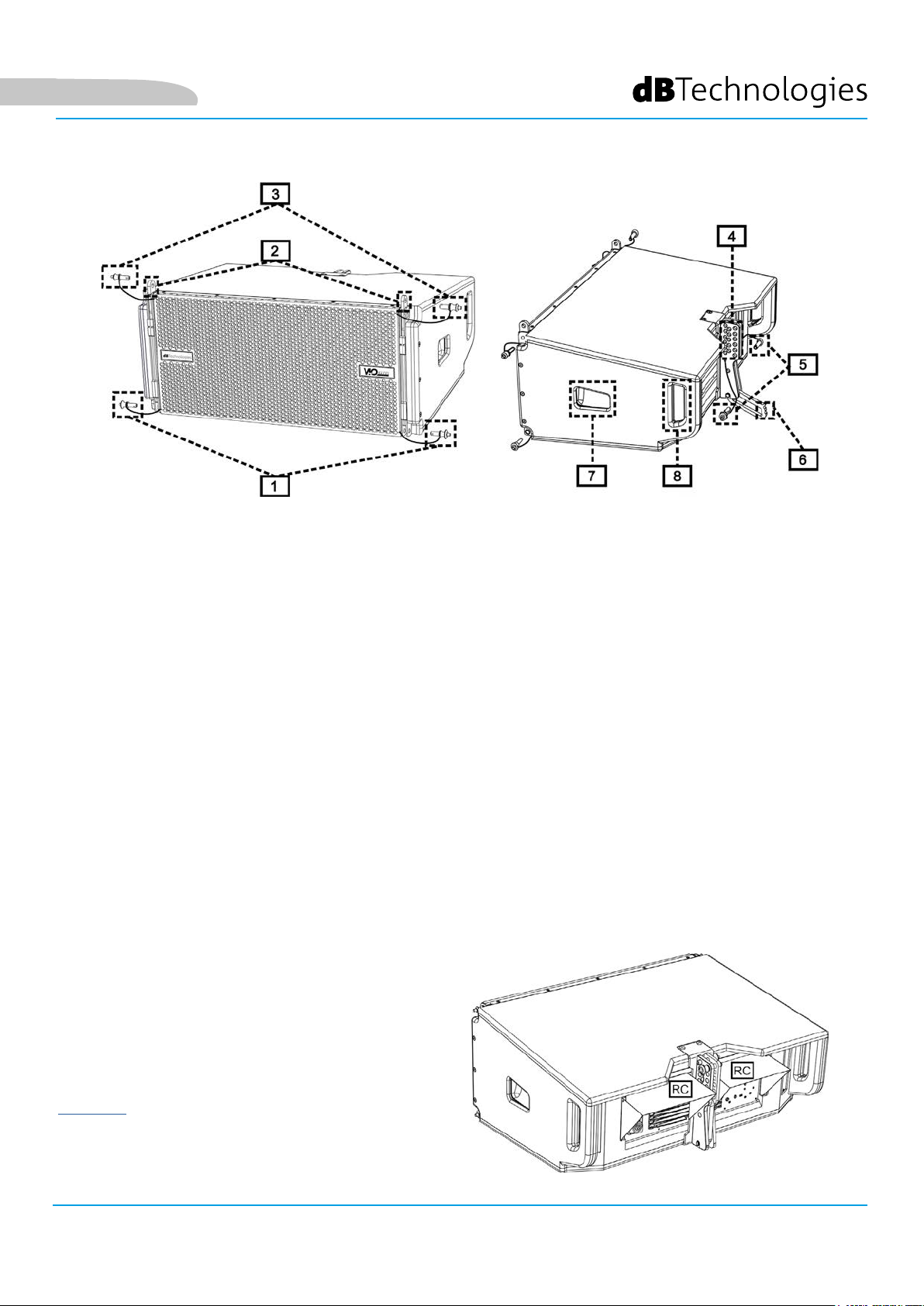
Deutsch
MECHANIK
Die Modul-Ergonomie und eine schnelle Montage des Line-Arrays sind gewährleistet durch:
VORDERSEITE
1) Unteres Verankerungssystem für den Anschluss anderer Module oder der DRK-210-Flybar (in gestapelter
Konguration).
2) Versenkbare Halterungen für die Verankerung an einem oberen Modul (oder an der DRK-210 Flybar in
Flown-Konguration).
3) Stifte zur Befestigung der versenkbaren Halterungen in Offen- / Schließstellung [2].
RÜCKSEITE
4) Zentrale Halterung. Mithilfe des Schilds mit Winkelgradmarkierungen kann der Winkelgrad des LineArray-Moduls ausgewählt werden.
Einstellungen sind ab 1 Grad möglich (Bereich von 0 bis 10 °).
5) Stifte zur Fixierung des Neigungswinkels: Hierzu werden jeweils nur 1 Stift in der Flown-Konguration
und 2 Stifte in der gestapelten Aufstellung benötigt. Siehe dazu die Abbildungen auf Seite 9.
6) Beweglicher Arm mit Langloch. Dieser wird an der Halterung [4] angeordnet und xiert den eingestellten
Winkel mechanisch mithilfe der Stifte [5].
SEITENTEILE RECHTS UND LINKS
7) Griff, der für die Gewichtsverteilung des Gehäuses optimal positioniert ist.
8) Rückseitiger Griff, der das Anheben der Rückseite des Moduls bei xierter Vorderseite erleichtert.
Die VIO-L210-Module sind außerdem auf der
Rückseite mit 2 Regenabdeckungen ausgestattet, um
den Verstärker vor Wasser zu schützen und auch bei
kritischen Witterungsbedingungen zu betreiben zu
können. Diese werden der Einfachheit halber nicht
mehr in den folgenden Zeichnungen gezeigt.
Nähere Informationen zum Flybar (siehe Abschnitt
ZUBEHÖR) nden Sie im entsprechenden Handbuch.
VIO-L210 Art.-Nr. 420120248 REV. 1.1
65
Page 66

Deutsch
Die Montage der zwei Module A und B erfordert einige einfache Schritte:
• Am Modul A die Stifte [3] entfernen, die versenkbaren Halterungen [2] anheben und mit den Stiften [3] an
der neuen Position befestigen.
• Entfernen Sie die Stifte [1] von Modul B, setzen Sie sie auf das Modul A und setzen Sie die Halterungen [2]
wie dargestellt ein. Befestigen Sie dann die Vorderseite der beiden Module mit den Stiften [1] des Moduls
B.
• Auf der Rückseite die Stifte [5] von den hinteren Halterungen [4] entfernen. Setzen Sie dann den
beweglichen Arm [6] des Moduls B in die Halterung [4] des Moduls A ein. Die nächste Seite zeigt im Detail
die Befestigung des Winkels auf der Rückseite zwischen den beiden Modulen.
VIO-L210
Art.-Nr. 420120248 REV. 1.1
66
Page 67

Deutsch
BEISPIEL 3 GRAD
Das Beispiel zeigt das Einstellen eines 3-Grad-Winkels zwischen 2 Modulen.
Bevor Sie einen anderen Vorgang durchführen, stellen Sie sicher, dass nach dem Einsetzen des beweglichen Arms
[6] das Langloch im gewählten Winkel in der Schlaufe liegt (siehe Abbildung).
• FLOWN-KONFIGURATION: nur 1 Stift in das Loch im gewählten Winkel einführen. Der zweite Stift kann in das
Loch „STIFTHALTER“ eingefügt werden. Beachten Sie, dass diese Art der Konguration während der Montage
eine Änderung der ausgewählten Winkel einfach durch Bewegen des entsprechenden Stifts (im beweglichen
Arm eingesetzt) ermöglicht.
• STAPEL-KONFIGURATION: Sobald der Stift [5] in das Loch des gewählten Winkels eingesetzt wird, heben
Sie Modul B so weit an, wie es der bewegliche Arm [6] erlaubt. Dann den zweiten Stift in die Stellung
„WINKELSICHERER“ stecken und das Modul B loslassen. Auf diese Weise wird das Modul B vollständig durch
die 2 Stifte auf der Rückseite blockiert.
Achten Sie nach Abschluss der Montage darauf, dass alle Stifte vollständig eingesteckt und gut xiert sind.
VIO-L210 Art.-Nr. 420120248 REV. 1.1
67
Page 68
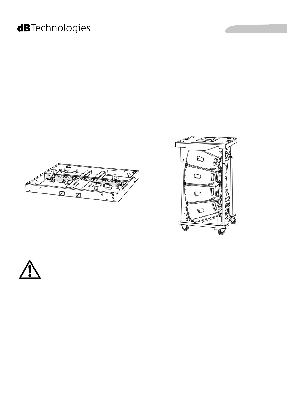
ZUBEHÖR
Für eine schnelle Montage sind optional folgende Zubehörteile vorgesehen:
• DRK-210, Flybar für Flown- und gestapelte Verwendung der Line-Array VIO-L210-Module.
• DT-VIOL210, Wagen zum Transport von bis zu vier VIO-L210-Modulen. Mithilfe dieses Zubehörteils
kann, ausschließlich für Transportzwecke, ein DRK-210-Flybar auf dem Deckel angebracht werden.
Deutsch
DRK-210
DT-VIOL210
ACHTUNG!
• Verwenden Sie nur Zubehör und Kongurationen, die in diesem Handbuch beschrieben sind, und
arbeiten Sie gemäß den Anweisungen in den mit dem Zubehör gelieferten Anleitungen.
• DRK-210 ist zur Aufhängung von bis zu 25 VIO-L210-Modulen (oder 16 Submodulen) mit maximal
750 kg Gewicht über einen einzelnen Koppelpunkt ausgelegt.
Die VIO-L210- Aufhängungskomponente ermöglicht den Anschluss von bis zu 10 Modulen (max.
300 kg) ohne Einschränkung der Winkeleinstellung des Line Arrays. Jede andere Konguration
oder Informationen bezüglich der Systemdaten, wie z. B. der maximalen Kapazität und der
Befestigungspunkte, müssen vor der Installation mit der Software dBTechnologies Composer
überprüft werden (siehe entsprechenden Abschnitt in dieser Bedienungsanleitung). Die Software
ist auf der Website www.dbtechnologies.com unter der Kategorie DOWNLOADS kostenlos
erhältlich.
Für jegliche weitere Informationen nehmen Sie bitte Bezug auf die entsprechenden Bedienungsanleitungen.
Konsultieren Sie für alle Updates auf Accessoires bitte www.dbtechnologies.com
VIO-L210
68
Art.-Nr. 420120248 REV. 1.1
Page 69
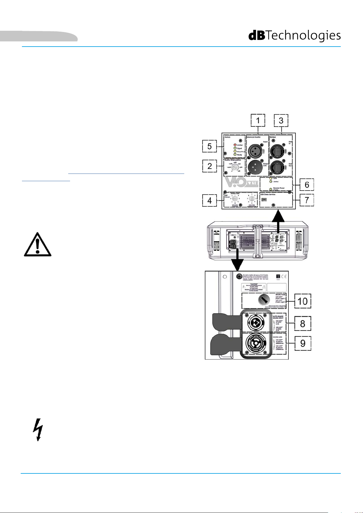
Deutsch
EIGENSCHAFTEN DES VERSTÄRKUNGS- UND STEUERBEREICHS
Der digitale Verstärker der Klasse D ist das Herzstück des
VIO-L210.
Der ermöglicht auf geräuscharme und efziente Weise die
Bereitstellung von bis zu 900 W RMS, ohne die Notwendigkeit
einer Lüftungsanlage. Das System wird von einem leistungsfähigen DSP gesteuert, wodurch der Line Array in jedem Verwen-
dungskontext sofort und schnell konguriert werden kann.
Dank der Möglichkeit der Netzwerkverbindung mit
RDNet können die Panel-Parameter mit der Software
„DBTECHNOLOGIES NETWORK“ ferngesteuert werden
(siehe Abschnitt DSP-VOREINSTELLUNGSPARAMETER UND
FERNBEDIENUNG).
Das Panel des DIGIPRO G3 verfügt über:
• Eingang, Ausgang und Steuerbereich
• Versorgungsbereich
ACHTUNG!
• Versperren Sie nicht die hinteren Kühlkörper
des Verstärkers. Wenn sich das Modul übermäßig
erwärmt, reduziert sich allmählich die Lautstärke,
bis das VIO-L210 thermisch wieder stabilisiert ist.
Das Niveau wird automatisch wiederhergestellt,
wenn die normale Betriebstemperatur erreicht ist.
• Versuchen Sie nicht, den Verstärker zu öffnen.
• Bei Funktionsstörungen sofort den Strom
abschalten, indem Sie das Modul vom Stromnetz
trennen, dann wenden Sie sich bitten an einen
autorisierten Techniker.
• Es empehlt sich, hochwertige Kabel mit OriginalNeutrik®-Steckverbindern zu verwenden. Überprüfen
Sie die Kabel regelmäßig auf deren Unversehrtheit.
• Der Lautsprecher wird mit einer montierten
Sicherung für den Betrieb im Bereich 220-240 V
geliefert. Wenn Sie im Spannungsbereich 100-120 V
arbeiten müssen:
1. Trennen Sie alle Verbindungen,
einschließlich der Stromversorgung.
2. Warten Sie 5 Minuten.
3. Ersetzen Sie die Sicherung durch die im Lieferumfang enthaltene Sicherung für den
Bereich 100-120 V.
BEREICH
UND STEUERUNG
EINGANG, AUSGANG
BEREICH
STROMVERSORGUNG
ACHTUNG!
• Entfernen Sie niemals das Frontschutzgitter des Produkts.
Um die Gefahr eines Stromschlags im Falle einer versehentlichen Beschädigung oder beim Austausch des Schutzgitters (nur von einem Service-Mitarbeiter durchzuführen), müssen Sie das Produkt zuvor vom Stromnetz trennen.
Schließen Sie das Netzteil nicht an, wenn das Schutzgitter nicht angebracht ist.
VIO-L210 Art.-Nr. 420120248 REV. 1.1
69
Page 70

Deutsch
INPUT-, OUTPUT- UND STEUERBEREICH
1. AUDIO-EINGANG UND RÜCKLAUF („symmetrisches Audio“)
Eingang und Ausgang kompatibel mit symmetrischen XLR-Kabeln.
Insbesondere wird der „Eingang“ für die Verbindung mit dem vom Mischer oder einem anderen Lautsprecher
stammenden Audiosignal verwendet, der „Ausgangs-Anschluss“ wird für den Rücklauf des Signals zu den anderen
Modulen des Line Arrays in Daisy-Chain-Konguration verwendet.
2. AUDIO-ANPASSUNG
Ermöglicht die Einstellung der Dämpfung des Moduls über die Eingangslautstärke.
Vor Beginn der Montage des Line Arrays auf 0 dB setzen.
3. EINGANG UND RÜCKLAUF DER RDNet-NETZWERKVERBINDUNG
Abschnitt ist mit Netzwerkkabel mit etherCON / RJ45-Steckverbindern kompatibel.
Insbesondere sollte „Daten Ein“ mit Geräten wie RDNet Control 2 oder Control 8 verbunden sein; „Daten Aus“
kann für den Neustart des Netzwerks zu anderen Modulen des Line Arrays in einer Daisy-Chain-Konguration
verwendet werden.
4. DSP-VOREINSTELLUNG
Drehregler zur Akustikeinstellung des Line Arrays.
Es empehlt sich, diese Bedienelemente (oder die gleichen Parameter über die RDNet-Verbindung entfernt) zu
verwenden, um das akustische Verhalten in Abhängigkeit von der Anzahl der Module und deren Orientierung
zu optimieren. Weitere Einzelheiten zur Verwendung von „SPEAKER COUPLING“ und „HIGH FREQUENCY
COMPENSATION“ nden Sie im AbschnittPARAMETRI DSP VOREINSTELLUNG E CONTROLLO REMOTO.
5. STATUS-LEDs
LEDs für den Betrieb des Moduls Eine Tabelle auf der nächsten Seite fasst die Bedeutung der verschiedenen LEDs
zusammen.
6. STEUER-LEDs
Betriebs-LEDs des Moduls mit Vernetzung (RDnet)
Wenn „Anschluss“ aktiviert ist, bedeutet dies insbesondere, dass das RDNet-Netzwerk aktiv ist und das Gerät erkannt
hat. Wenn „Active“ blinkt, bedeutet dies, dass der Datenaustausch hergestellt ist. „Remote Preset Active“ zeigt an,
dass alle lokalen Bedienelemente des Verstärker-Bedienfelds von der RDNet-Fernsteuerung umgangen werden.
7. USB-DATENSERVICE
Ein Mini-USB-Port B, der nur für die Firmware-Aktualisierung des Produkts verwendet wird. Weitere Informationen
nden Sie im Abschnitt „FIRMWARE-AKTUALISIERUNG“.
VIO-L210
Art.-Nr. 420120248 REV. 1.1
70
Page 71
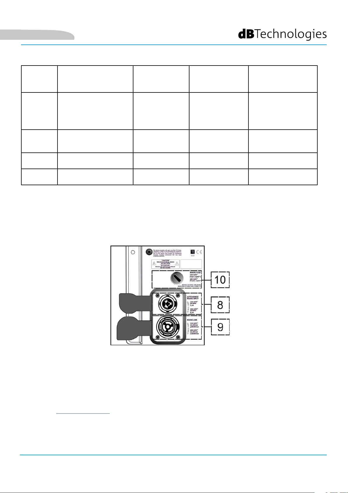
Deutsch
LED-TYP BEIM EINSCHALTEN
DES LAUTSPRECHERS
LIMITER ERLOSCHEN ERLOSCHEN,
SIGNAL
STUMM /
PROT
BEREIT ERLOSCHEN DAUERHAFT
ERLOSCHEN BLINKEN
LEUCHTET FÜR EINIGE
SEKUNDEN
BETRIEB
NORMAL
EIGENSTÄNDIGES
AUFLEUCHTEN
NUR BEI EINEM
EINGRIFF
MIT SIGNAL
ERLOSCHEN KURZES BLINKEN DAUERHAFT
LEUCHTEND
Tabelle der Status-LED-Signale
VERSORGUNGSBEREICH
WARNUNG
GENERISCHE
KURZES
BLINKEN
SIGNAL NORMAL
AUDIO-EIN
EINGANG
DAUERHAFT LEUCHTEND
ABSCHALTUNG
WEGEN DES
LAUTSPRECHERS
KONTINUIERLICHES
ZYKLISCHES BLINKEN
ERLOSCHEN
LEUCHTEND
ERLOSCHEN
8. VERSORGUNGSVERBINDER „MAINS INPUT”
Kompatibel mit dem powerCON TRUE1®-Verbinder ist die Stromversorgung mit der Auto-Bereich-Funktion
ausgestattet. Sobald der entsprechende Bereich deniert ist, wird bei Bedarf durch Austausch der Sicherung die
Spannung im Intervall [100-120V ~] oder [220-240V ~] automatisch erkannt.
9. VERSORGUNGSRÜCKLAUF „MAINS-ANSCHLUSS”
Kompatibel mit einem powerCON TRUE1®-Stecker zum Rücklauf der Stromversorgung anderer Module.
Die maximale Anzahl der Module, die in einem neu gestarteten System angeschlossen werden können, nden Sie
im Abschnitt TECHNISCHE DATEN.
10. NETZWERKSICHERUNG
Gehäuse für die Netzsicherung
VIO-L210 Art.-Nr. 420120248 REV. 1.1
71
Page 72
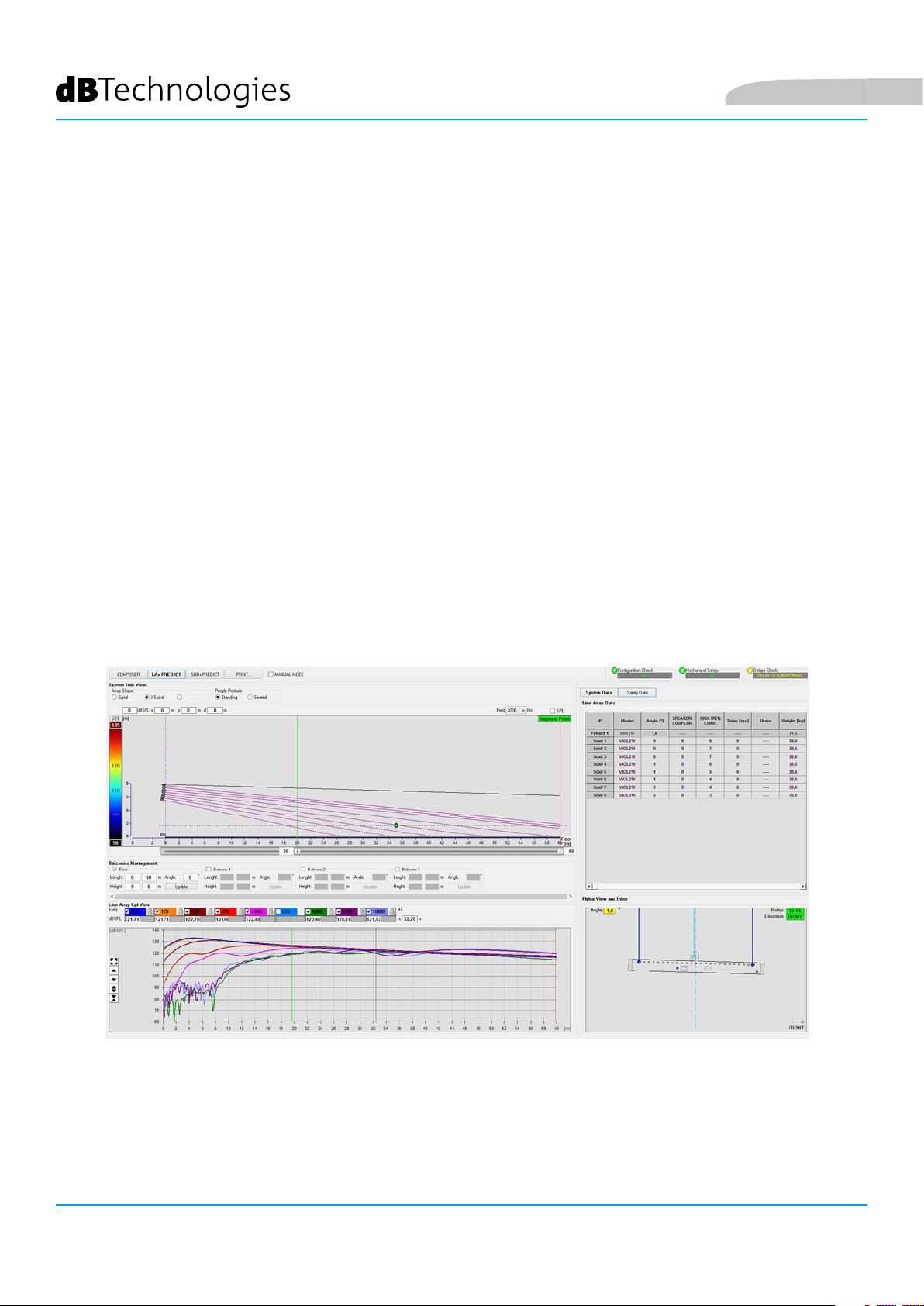
Deutsch
2. DBTECHNOLOGIES COMPOSER
DBTechnologies Composer-Software, die zum kostenlosen Download unter www.dbtechnologies.com zur
Verfügung steht, ist ein Instrument für die korrekte Gestaltung der für die gesamte VIO-Serie empfohlenen
Audiosysteme.
Es bietet eine Lösung dafür, die Räume zu sonorisieren und zeigt dazu den Winkel der Line-Array-Module
an, um die gewünschte Abdeckung und die Voreinstellung zu erreichen.
Obwohl es sich um ein prädiktives Instrument handelt, ermöglicht es eine Reihe von manuellen
Einstellungen, um die Konguration nach beliebigen Schallfeldmessungen oder spezischen Anforderungen
zu verfeinern.
Schließlich ist es ein wirksames Instrument zur Beurteilung der Sicherheit der Anlage. Durch die Simulation
des statischen Verhaltens der Flybar und die Anzeige der mechanischen Kräfte am Spiel ermöglicht es, zu
überprüfen, wie viele Module installiert werden sollten, bevor ein Überlastungszustand erreicht wird.
Die Hauptabschnitte des dBTechnologies Composer sind:
• COMPOSER - allgemeine Ansicht, die die Eingabe der Projektdaten erlaubt
• LAs PREDICT - mit Sicherheitssimulation, Konguration und Test von Line Arrays
• SUBs PREDICT - mit Sicherheitssimulation, Konguration und Test von Subwoofern
Dieses Kapitel beschreibt einige Details der Software in Bezug auf Installation und Sicherheit, insbesondere
für die FLOWN-Konguration des VIOL210-Line-Arrays.
VIO-L210
72
Art.-Nr. 420120248 REV. 1.1
Page 73
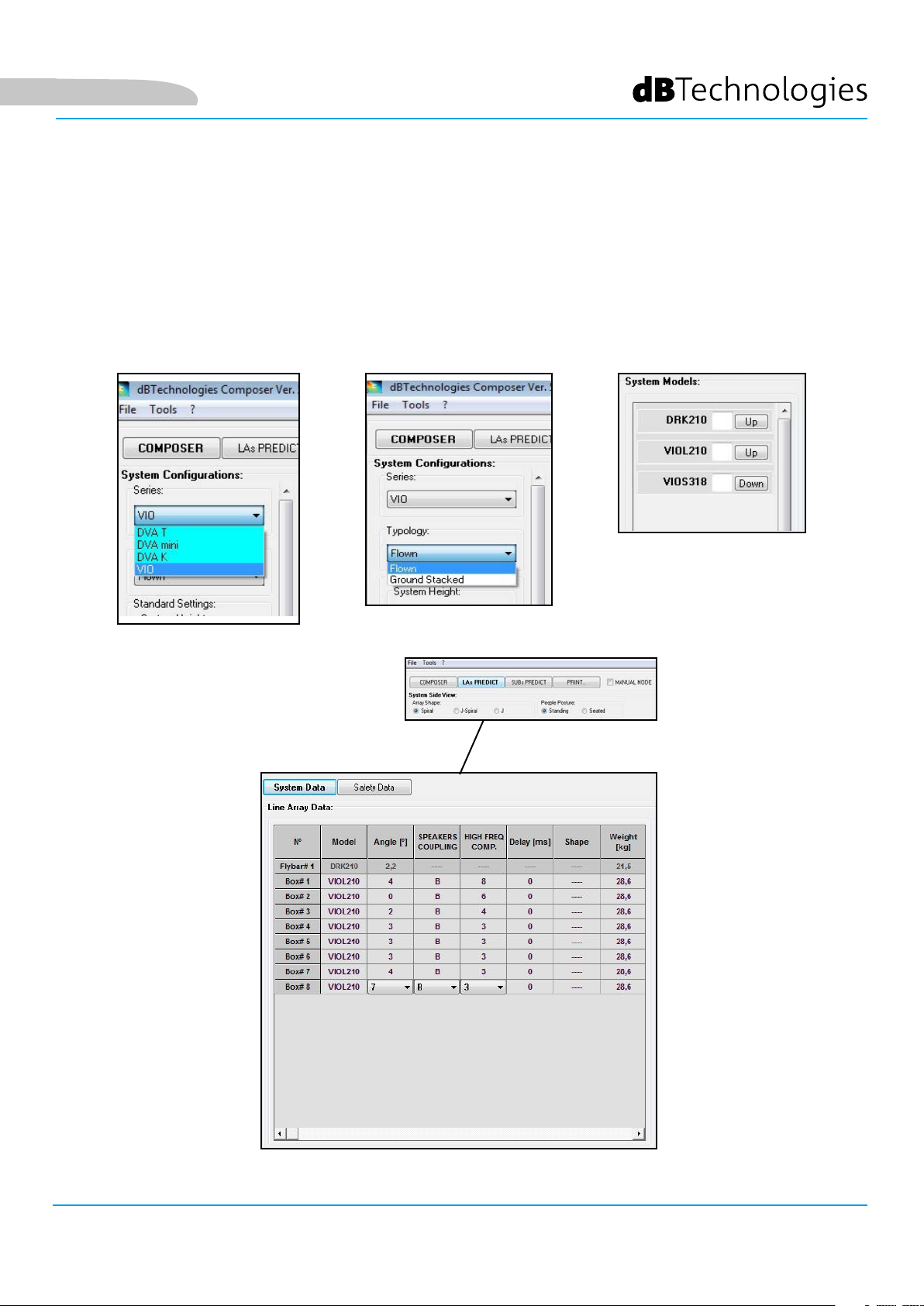
Deutsch
Der Abschnitt „LAs PREDICT“ enthält alle Informationen, die für die ordnungsgemäße Konguration,
überogen oder gestapelt, eines VIO-Systems erforderlich sind. Um darauf zuzugreifen, müssen Sie zuerst
die Projektdaten eingeben, die im Abschnitt Komponieren enthalten sind.
Die Systemdaten-Seite bietet die folgenden Vorschläge: die Winkeleinstellung der verschiedenen Module,
verschiedene Parameter, die sich auf den Abschnitt „DSP-Voreinstellung“ und die Winkeleinstellung
der DRK-210 Flybar beziehen. Diese letzte Winkeleinstellung kann auf dem Feld unter Verwendung
eines Laser-Inklinometers detektiert werden, das nicht im Lieferumfang enthalten ist, dessen Aufbau im
Handbuch des DRK-210 dargestellt ist.
VIO-L210 Art.-Nr. 420120248 REV. 1.1
73
Page 74

Im Bereich Sicherheitsdaten nden Sie eine Simulation des
Schwerpunkts beim Flown-System mit DRK-210.
Insbesondere kann der Benutzer zwischen EUROCODE 3
oder BGV-C1 Referenzen wählen.
Die zugehörigen Ergebnisse werden grün, wenn sicher
und rot dargestellt, wenn die maximal zulässige Belastung
für den gewählten Winkel überschritten wird (und daher
verboten ist).
Deutsch
VIO-L210
74
Art.-Nr. 420120248 REV. 1.1
Page 75

Deutsch
Wenn nur ein Motor in einer Flown-Konguration
verwendet wird, zeigt „SINGLE“ die Position des einzelnen
Hakens an, der auf dem DRK-210 verwendet werden soll
(der abgestufte Positionen erfordert, die von einem Etikett
auf dem Flybar beschrieben sind).
Zusätzlich gibt es eine „FRONT“ oder „REAR“ Richtung für
das Lenken des Hakens für den Motor.
Im Falle von „FRONT“ sollte die Referenz (siehe Abbildung
unten und gezeigt als LOAD ADAPTER REFERENCE SIDE) in
Richtung der Vorderseite des Line Arrays platziert werden,
im Falle von „REAR“ sollte sie auf die Rückseite des Line
Arrays gerichtet sein.
Wenn stattdessen zwei Motoren verwendet werden,
sollten die Haken immer an den Enden der Fly-bar
angeordnet sein (in diesem Fall ist die Richtung der
Platzierung irrelevant).
Weitere Informationen zur dBTechnologies Composer
Software nden Sie im entsprechenden Handbuch zum
kostenlosen Download unter: www.dbtechnologies.com.
SCHILD MIT WINKELGRADMARKIERUNGEN AUF DER SEITE DES FLYBARS
LOAD ADAPTOR REFERENCE SIDE
VIO-L210 Art.-Nr. 420120248 REV. 1.1
75
Page 76

Deutsch
3. DSP-VOREINSTELLUNGSPARAMETER UND FERNSTEUERUNG
Der Einsatz eines Line Arrays bringt eine Reihe von Vorteilen in verschiedenen Kontexten mit sich,
insbesondere:
• homogene SPL entlang des Frontvektors der Lautsprecher, was besonders bei mittleren und langen
Distanzen zu einem
• direkten akustischen Verhalten führt, das es erlaubt, den Klang präzise auf das Publikum zu
fokussieren und unnötige Verluste in Bereichen zu vermeiden, in denen keine akustische Abdeckung
erforderlich ist.
Die umsetzbare Optimierung der Line Arrays berücksichtigt das Verhalten des Systems entsprechend der
Frequenz:
• Bei Vergrößerung der Distanz vom Line Array erhöht sich die Luftdämpfung. Dies wirkt sich
insbesondere auf hohe Frequenzen aus.
• Bei Vergrößerung des Winkels zwischen den Elementen des Line Arrays verringert sich die
Mittenfrequenzphasenkopplung
• mit zunehmender Anzahl der Module der Line Array addieren sich die tiefe Frequenzen akustisch
kohärent.
Die akustische Konguration in einem Line Array der VIO-L210
Module lässt sich dank der von DSP verwalteten Steuerfunktionen
optimieren. Die Benutzeroberäche ist einfach und unkompliziert,
mit zwei Drehreglern im Abschnitt „DSP-Voreinstellung“ (4) und
einer Erläuterungsetikette auf der Seite des Verstärkers:
• Stellen Sie den Drehregler „SPEAKER COUPLING“ entsprechend
der im Line Array verwendeten Modulanzahl ein Der Drehregler
wirkt auf die mittleren Frequenzen ein und sollte auf die
folgenden Positionen gestellt werden:
• A - 2 bis 6 Lautsprecher
• B - 7 bis 8 Lautsprecher
• C - 9 bis 10 Lautsprecher
• D - 11 bis 12 Lautsprecher
• E - 13 bis 14 Lautsprecher
• F - über 15 Lautsprecher
• G - um die tiefen Frequenzen zu erhöhen
(Front-ll Stand-Alone-Betrieb)
VIO-L210
76
Art.-Nr. 420120248 REV. 1.1
Page 77

Deutsch
• Die Einstellung des Drehreglers
„HOCHFREQUENZKOMPENSATION“ hängt von der
Installationsart und der Winkeleinstellung des Line Arrays ab.
Dieser Drehregler wirkt auf die mittleren Frequenzen und sollte
eingestellt werden auf die Position:
• 1 - FLAT (ohne Betonung einer bestimmten Frequenz)
• 2 - Front-ll mit Publikum in einer Entfernung von 0 bis 5 m (16 f)
• 3 - mit Publikum in einer Entfernung von 6 bis 20 m (17-66 f)
• 4 - mit Publikum in einer Entfernung von 21 bis 30 m (67-98 f)
• 5 - mit Publikum in einer Entfernung von 31 bis 40 m (99-131 f)
• 6 - mit Publikum in einer Entfernung von 41 bis 50 m (132-164 f)
• 7 - mit Publikum in einer Entfernung von 51 bis 60 m (165-197 f)
• 8 - mit Publikum in einer Entfernung ab 61 m (17.198 f)
• All diese Parameter können, sobald die RDNet-Verbindungen ordnungsgemäß hergestellt ist, mit
der Fernsteuerung über die Software DBTECHNOLOGIES NETWORK eingestellt werden (kostenloser
Download auf der Webseite www.dBTechnologies.com in der Kategorie DOWNLOADS). Bei
der Bedienung über Fernsteuerung werden die lokalen Bedienelemente in den Bedienfeldern
des VIO-L210-Moduls umgangen. Mit dieser Software ist es außerdem möglich, eine größere
Anzahl von Parametern zu steuern (weitere Informationen nden Sie im kompletten Handbuch
DBTECHNOLOGIES NETWORK).
Die zuletzt auf VIOL210 gespeicherten Einstellungen (mit der Software DBTECHNOLOGIES
NETWORK) können später auf dem Lautsprecher ohne RDNet-Fernbedienung abgerufen
werden. Hierzu den Drehregler SPEAKER COUPLING auf die Position Service / User stellen.
VIO-L210 Art.-Nr. 420120248 REV. 1.1
77
Page 78

4. VERBINDUNGEN
VERBINDUNG UND START DER STROMVERSORGUNG
A
B
C
Deutsch
MODUL 1
MODUL 2
Die obige Abbildung zeigt eine allgemeine Verbindung, bei der das Modul 1 über Modul 2 liegt.
Verwenden Sie dazu Kabel mit powerCON TRUE1®-Steckverbindern (nicht mitgeliefert).
• Schließen Sie die Stromversorgung des Moduls 1 AUTO-RANGE MAINS INPUT (A) an.
• Starten Sie die Stromversorgung von Modul 1 zu Modul 2, indem Sie den Ausgang MAINS LINK (B)
des Moduls 1 mit dem Eingang AUTO-RANGE MAINS INPUT (C) des Moduls 2 verbinden.
• Wiederholen Sie diesen Vorgang, bis Sie die maximal zulässige Anzahl der Line-Array-Module
angeschlossen haben (siehe Kapitel TECHNISCHE DATEN).
ACHTUNG!
• Die Kabel müssen ordnungsgemäß dimensioniert sein und das Design,
die Installation und die Tests des Systems dürfen nur von qualiziertem
Personal ausgeführt werden. AEB Industriale lehnt jede Verantwortung im
Falle von Kabeln ab, die nicht konform sind, nicht zertiziert sind und mit
dem ordnungsgemäßen Layout des Systems und den für das Land gültigen
Vorschriften unvereinbar sind.
VIO-L210
78
Art.-Nr. 420120248 REV. 1.1
Page 79

Deutsch
VERBINDUNG UND RÜCKLAUF VON AUDIOSIGNAL UND RDNET
A
MODUL 1
B
MODUL 2
A
B
C
C
Die obige Abbildung zeigt eine allgemeine Verbindung, bei der das Modul 1 über Modul 2 liegt und
diesmal Audio- und Netzwerkverbindung zeigt. Verwenden Sie dazu keine Kabel mit XLR-(Audio) und
etherCON- / RJ45- (Netzwerk) Anschlüssen. Weitere Informationen zu den verfügbaren Kabeltypen
nden Sie auch auf der nächsten Seite.
• Für den Audioanschluss verbinden Sie das Kabel von MIXER / LINE mit dem Eingang BALANCED
AUDIO INPUT (A) des Moduls 1 des Line Arrays. Starten Sie das Signal zwischen dem ersten und
zweiten Modul. Verbinden Sie hierzu den Ausgang BALANCED AUDIO OUTPUT (B) des Moduls 1
mit dem Eingang BALANCED AUDIO INPUT (C) des Moduls 2.
• Wiederholen Sie diese Vorgangsweise zwischen dem zweiten und dem dritten Modul und so
weiter, bis alle Module des Line Arrays verbunden sind.
• Verbinden Sie für die Netzwerkverbindung den DATEN EIN (A) -Anschluss des Moduls 1 mit der
Fernbedienung (RDNet CONTROL 2 oder RDNet CONTROL 8). Starten Sie das Signal neu, indem
Sie DATEN AUS (B) von Modul 1 an DATEN EIN (C) von Modul 2 anschließen.
• Wiederholen Sie diese Vorgangsweise zwischen dem zweiten und dem dritten Modul und so
weiter, bis alle Module des Line Arrays verbunden sind.
ACHTUNG!
• Ersetzen Sie eventuell beschädigte Kabel, so dass Funktionsstörungen und
eine schlechte Klangqualität vermieden werden können.
VIO-L210 Art.-Nr. 420120248 REV. 1.1
79
Page 80
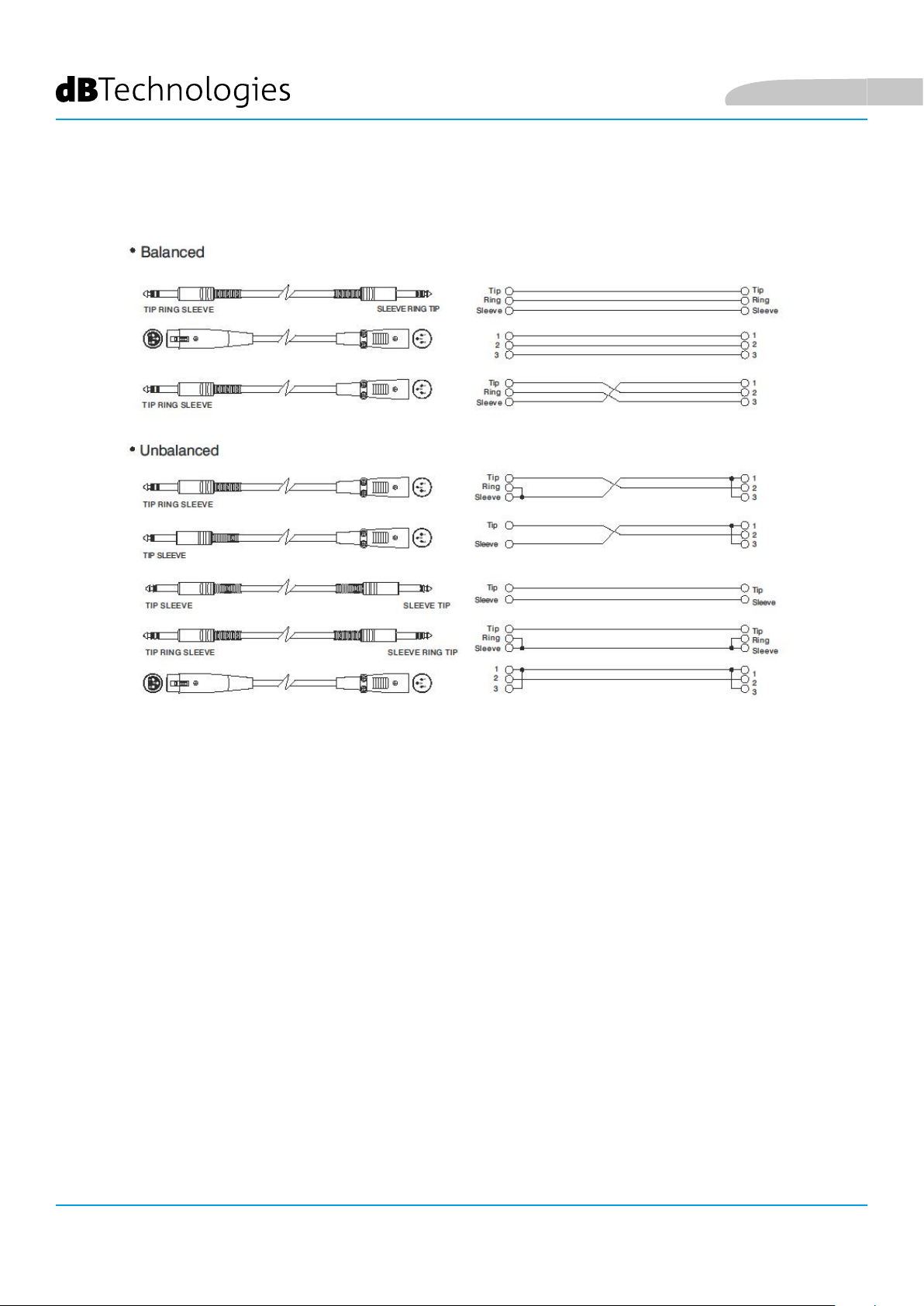
Deutsch
VIO-L210
Art.-Nr. 420120248 REV. 1.1
80
Page 81

Deutsch
5. INSTALLATION UND KONFIGURIERUNG
VERPACKUNGSINHALT
Überprüfen Sie, ob die Lieferung des Moduls VIO-L210 vollständig ist. Die Verpackung enthält:
• VIO-L210-Modul
• Sicherung für den Betrieb im Bereich 110-120 V ~ (siehe Abschnitt EIGENSCHAFTEN DES
VERSTÄRKUNGS- UND STEUERBEREICHS für weitere Informationen)
• Quick Start-Anleitung und Garantieschein
ACHTUNG!
Produkt und Zubehör dürfen nur von qualiziertem Personal gehandhabt werden! Stellen Sie sicher, dass die
Anlage stabil und sicher aufgestellt wird, um gefährliche Personen-, Tier- und / oder Sachschäden zu vermeiden. Der Benutzer ist verpichtet, die Vorgaben und die gesetzlichen Vorschriften über die Sicherheit des
Landes, in dem das Produkt verwendet wird, zu befolgen. Für den sicheren Gebrauch regelmäßig die Funktionstüchtigkeit aller Teile und die Unversehrtheit vor Gebrauch überprüfen.
Planung, Berechnungen, Installation, Testen und Wartung von Schranksystemen oder professionellen Audiostapeln dürfen nur von autorisiertem Personal durchgeführt werden. AEB Industriale ist nicht verantwortlich für
unsachgemäße Installationen, die nicht den Sicherheitsanforderungen entsprechen.
FLOWN-INSTALLATION (BEISPIEL FÜR 1 ARRAY MIT 8 MODULEN)
• Verwenden Sie den DBTECHNOLOGIES COMPOSER, um die Projektparameter einzustellen.
• Überprüfen Sie, ob die lokalen Parameter der verschiedenen Module auf den einzelnen Verstärkerpanels
richtig eingestellt sind. Überprüfen Sie insbesondere gemäß dem Projekt: Audio-Dämpfung,
Lautsprecherkopplung und Hochfrequenzkompensierung. Alternativ können Sie per Fernzugriff und
in Echtzeit alle Parameter ändern, wenn das Line Array über das RDNet Netzwerk (DBTECHNOLOGIES
NETWORK) angeschlossen ist. In diesem Fall ist es auch eine gute Praxis, die ursprünglichen
Einstellungen des Projekts auf den VIO-L210-Modulen vor der Installation physisch zu replizieren. Weitere
Informationen nden Sie im Abschnitt DSP-VOREINSTELLUNGSPARAMETER UND FERNSTEUERUNG.
• Transportieren Sie über den DT-VIOL210 die ersten 4 Module und den DRK-210 Flybar an die Stelle, an
der das Line Array angehoben werden soll. Halten Sie einen zweiten Wagen (ohne Flybar) mit weiteren
4 Modulen für die folgenden Montagephasen des kompletten Line Arrays bereit. Alle relevanten
Informationen nden Sie in den Handbüchern dieses Zubehörs.
DIE ANGABEN ZUR
VERKABELUNG AUF DEN
FOLGENDEN ABBILDUNGEN
DIENEN LEDIGLICH DER
ERLÄUTERUNG.
VIO-L210 Art.-Nr. 420120248 REV. 1.1
81
Page 82
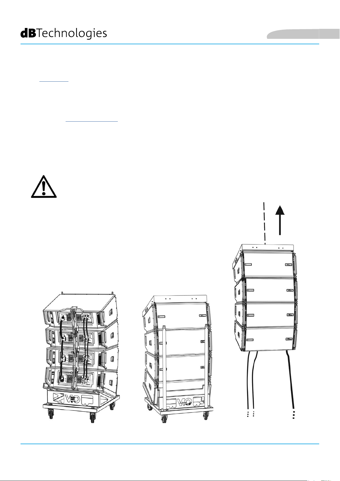
Deutsch
• Sichern Sie die Bremsen an den Rädern DT-VIOL210.
• Auf der Rückseite legen Sie die beweglichen Arme [6] in die Halterungen [4] ein, siehe dazu Abschnitt
MECHANIK.
• Setzen Sie die Stifte entsprechend den zuvor berechneten Winkeln in die Arme ein (für diesen Vorgang
müssen Sie die Module nicht heben).
• Die Audio-, RDNet- und Stromversorgungsanschlüsse wie in den vorstehenden Abschnitten beschrieben
herstellen (die maximale Anzahl der Stromanschlüsse in einem neu gestarteten System nden Sie im
Abschnitt TECHNISCHE DATEN).
• Entfernen Sie die obere Abdeckung und die Rohre auf der Rückseite des DT-VIOL210.
• Montieren Sie die DRK-210 Flybar auf dem oberen Modul entsprechend den Einstellungen, die mit dem
DBTECHNOLOGIES COMPOSER geprüft wurden.
• Die am DARK-210 verankerten 4 Module mit einem oder zwei Motoren und den entsprechenden
Takelagen (nicht mitgeliefert) anheben.
• Entfernen Sie die Bremsen von den Rädern des DT-VIOL210 und setzen Sie den Wagen wieder in die
Ruheposition.
ACHTUNG!
DRK-210 ist zur Aufhängung von bis zu 25 VIO-L210-Modulen
(oder 16 Submodulen) bis maximal 750 kg mit einem
einzelnen Koppelpunkt ausgelegt.
Die VIO-L210- Aufhängungskomponente ermöglicht den
Anschluss von bis zu 10 Modulen (max. 300 kg) ohne
Einschränkung der Winkeleinstellung des Line Arrays.
Jede andere Konguration oder Information bezüglich
der Systemdaten, wie z. B. die maximale Kapazität und
die Befestigungspunkte, müssen vor der Installation mit
der Software dBTechnologies Composer überprüft werden
(siehe Benutzerhandbuch). Die Software ist auf der Website
www.dbtechnologies.com unter der Kategorie Downloads
VIO-L210
82
Art.-Nr. 420120248 REV. 1.1
Page 83
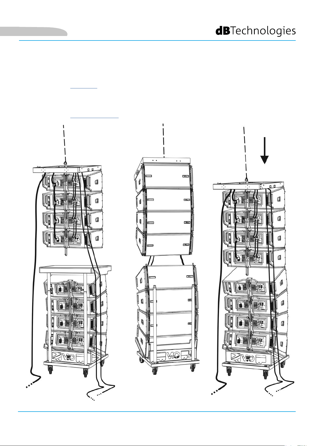
Deutsch
• Bringen Sie die 4 zusätzlichen Module mit einem zweiten DT-VIOL210-Wagen unter die 4 bereits
aufgehängten Module.
• Stellen Sie die Bremsen am Wagen fest und xieren Sie die Ecken, wie im vorherigen Schritt beschrieben.
• Entfernen Sie die Abdeckung und die vorderen Rohre des DT-VIOL210.
• Die 4 aufgehängten Module ordnungsgemäß absenken und einhaken, siehe dazu Beschreibungen im
Abschnitt MECHANIK für Vorder- und Rückseite beschrieben. Achten Sie beim Bewegen des oberen
hängenden Blocks auf diesen Schritt.
• Die Audio-, RDNet- und Stromversorgungsanschlüsse wie in den vorstehenden Abschnitten beschrieben
herstellen (die maximale Anzahl der Stromanschlüsse in einem neu gestarteten System nden Sie im
Abschnitt TECHNISCHE DATEN).
VIO-L210 Art.-Nr. 420120248 REV. 1.1
83
Page 84
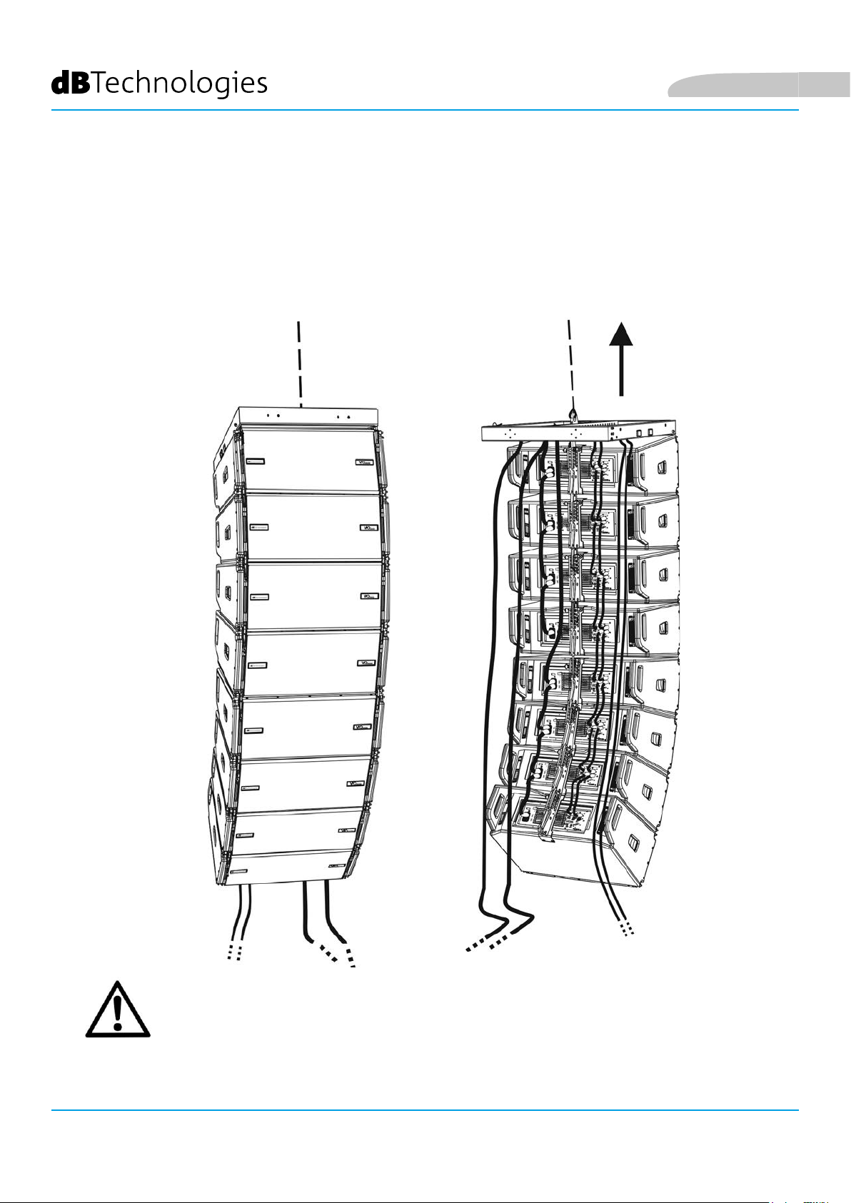
Deutsch
• Heben Sie das Line Array leicht an und überprüfen Sie die Aufhängung und die Winkeleinstellung. Falls
erforderlich prüfen Sie mit einem Laser-Neigungssensor (nicht mitgeliefert), dass die Neigung der Flybar
mit der Planung übereinstimmt. Prüfen Sie, ob alle Stifte vollständig eingesteckt und verriegelt sind.
• Entfernen Sie die Bremsen des DT-VIOL210-Wagens, schließen und entfernen Sie Ihn.
• Heben Sie das zusammengebaute Line Array mit maximaler Sorgfalt an.
• Wenden Sie jede andere Befestigungstechnik an, die für die sichere und stabile Verwendung des Line
Arrays erforderlich ist, auch unter Berücksichtigung aller atmosphärischen Phänomene, denen das Line
Array ausgesetzt sein kann.
VIO-L210
84
ACHTUNG!
• Niemals die Griffe, Halterungen oder andere Elemente des Lautsprechers als Halterungen
für Module oder System verwenden!
• Bei Verwendung im Freien empehlt es sich, das System zu verankern, um Schwingungen
durch Wind und Wetter zu vermeiden.
Art.-Nr. 420120248 REV. 1.1
Page 85
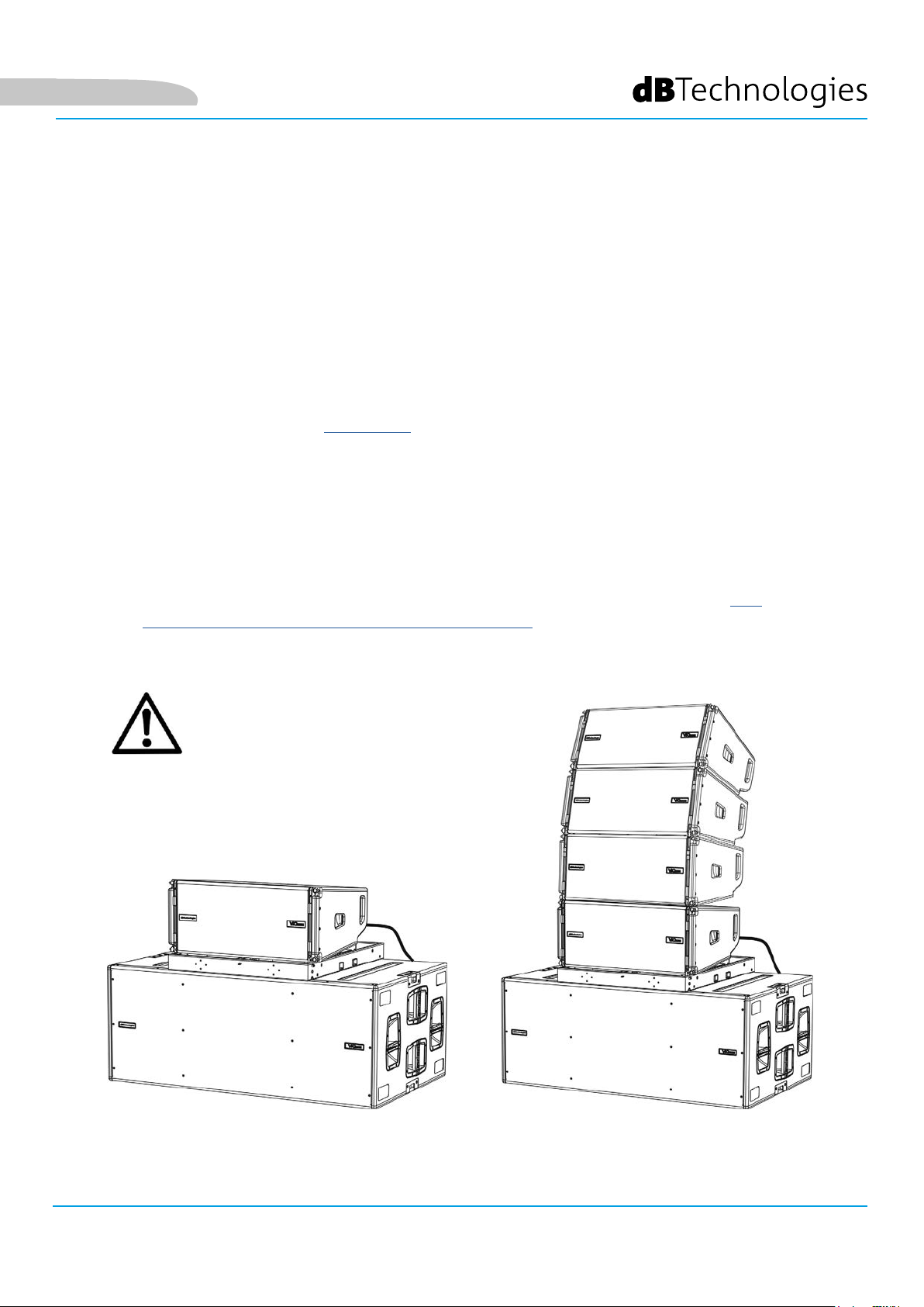
Deutsch
GESTAPELTE INSTALLATION (BEISPIEL FÜR 1 ODER 4 MODULE AUF SUB318)
• Es sollten nicht mehr als 4 Module übereinander auf der DRK-210-Flybar gestapelt werden.
• Verwenden Sie aus Sicherheitsgründen den DBTECHNOLOGIES COMPOSER, um die
Projektparameter einzustellen.
• Platzieren Sie die DRK-210-Flybar auf den SUB 318 (auf ebenem Grund ohne Neigung
installiert). Nähere Informationen zu diesem Zubehör nden Sie im kompletten Handbuch.
• Fügen Sie die VIO-L210-Module einzeln mit der zuvor berechneten Winkeleinstellung
ein, siehe dazu Abschnitt MECCANICA.
• Überprüfen Sie, dass die lokalen Parameter der verschiedenen Module auf den einzelnen
Verstärkerpanels richtig eingestellt sind. Überprüfen Sie insbesondere gemäß dem
Projekt: Audio-Dämpfung, Lautsprecherkopplung und Hochfrequenzkompensierung.
Alternativ können Sie per Fernzugriff in Echtzeit oder zu einem späteren Zeitpunkt alle
Parameter ändern, wenn das Line Array über das RDNet-Netzwerk (DBTECHNOLOGIES
NETWORK) angeschlossen ist. In diesem Fall ist es auch eine gute Praxis, die
ursprünglichen Einstellungen des Projekts auf den VIO-L210-Modulen vor der
Installation physisch zu replizieren. Weitere Informationen nden Sie im Abschnitt DSP
VOREINSTELLUNG PARAMETERS UND FERNBEDIENUNG.
• Führen Sie Audio-, RDNet- und Stromversorgungsanschlüsse wie in den vorstehenden
Abschnitten beschrieben aus.
ACHTUNG!
• Wenn die Auageäche
auch nur geringste Neigung
aufweist, ist es notwendig, eine
ordnungsgemäße Befestigung
mit den entsprechenden
mechanischen Mitteln und / oder
Montagebändern vorzunehmen.
VIO-L210 Art.-Nr. 420120248 REV. 1.1
85
Page 86

6. PROBLEMABHILFE
Das Modul lässt sich nicht einschalten:
1. Überprüfen Sie das Vorhandensein der korrekten, der Anlage vorgeschalteten Versorgung.
2. Überprüfen Sie, dass die Stromversorgung oder der Rücklauf der Stromversorgung korrekt sind.
Das Modul lässt sich einschalten, gibt jedoch keine Töne ab:
1. Überprüfen Sie, dass die Anschlüsse zum Audiosignaleingang oder der Rücklauf des Audiosignals
korrekt erfolgt sind.
2. Stellen Sie sicher, dass die Audio-Dämpfung auf 0 dB eingestellt ist.
3. Überprüfen Sie, ob die Audioquelle (Mischer) richtig angeschlossen und aktiv ist.
4. Überprüfen Sie im Falle einer RDNet-Netzwerkverbindung und -steuerung mit dem DBTECHNOLOGIES
NETWORK, dass die MUTE-Funktion deaktiviert ist.
Deutsch
Der Ton ist nicht völlig zufriedenstellend.
1. Überprüfen mithilfe der Software DBTECHNOLOGIES COMPOSER die Planung und die Installations- und
Kongurationsspezikationen.
2. Überprüfen Sie, ob die DSP-VOREINSTELLUNGS-Parameter tatsächlich auf dem Bedienfeld des Moduls
repliziert werden (insbesondere, wenn die Fernbedienung des Moduls nicht verwendet wird).
3. Überprüfen Sie im Falle einer RDNet-Netzwerkverbindung und -steuerung mit dem DBTECHNOLOGIES
NETWORK, dass sämtliche Parameter ordnungsgemäß eingestellt sind.
VIO-L210
86
Art.-Nr. 420120248 REV. 1.1
Page 87
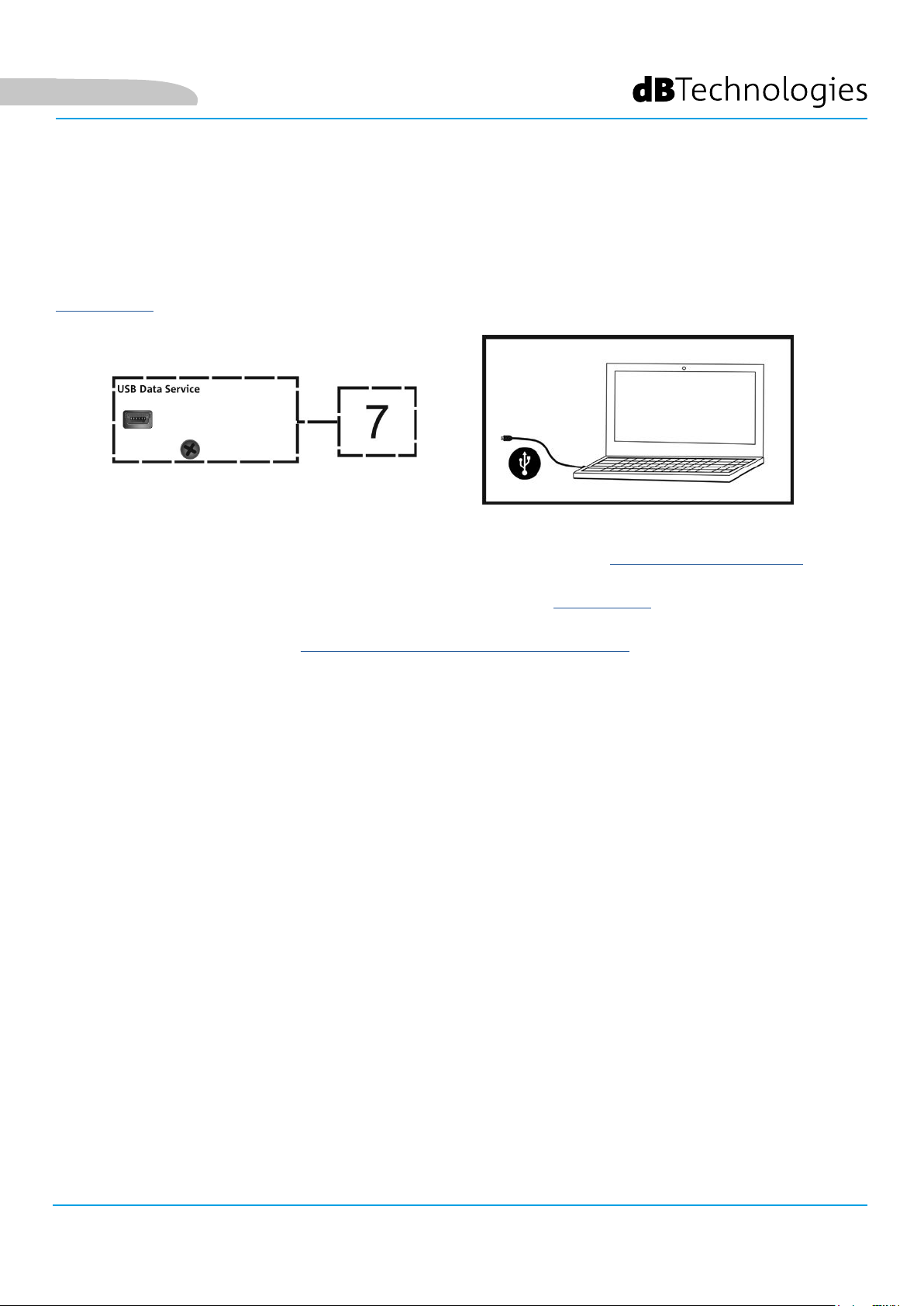
Deutsch
7. FIRMWARE-AKTUALISIERUNG
ES ist sehr wichtig, die Produkt-Firmware auf dem neuesten Stand zu halten, um die volle Funktionalität zu
gewährleisten. Überprüfen Sie regelmäßig die Website http://www.dbtechnologies.com unter dem Abschnitt
DOWNLOADS.
1. Laden und installieren Sie den USB BURNER MANAGER aus dem Abschnitt SOFTWARE & CONTROLLER auf
Ihren PC.
2. Laden Sie die ZIP-Datei der neuesten Firmware aus dem Abschnitt DOWNLOADS Ihres Produkts herunter.
3. Verbinden Sie das Produkt mit einem USB-Kabel (nicht mitgeliefert) mit einem geeigneten Steckverbindertyp
(siehe dieses Detail im Kapitel VERSTÄRKUNGS- UND STEUEREIGENSCHAFTEN).
4. Wählen Sie auf dem Bildschirm USB BURNER MANAGER oben rechts im Bildschirm „Datei öffnen“.
5. Wählen Sie die Datei mit der zuvor heruntergeladenen Firmware aus.
6. Folgen Sie den Anweisungen auf dem Bildschirm.
7. Klicken Sie auf „AKTUALISIEREN“.
VIO-L210 Art.-Nr. 420120248 REV. 1.1
87
Page 88
8. TECHNISCHE DATEN
ALLGEMEINE DATEN
Typ: 2-Wege Line-Array-Modul
AKUSTIK-DATEN
Frequenzgang [- 6 dB]: 67 - 20000 Hz
Frequenzgang [± 3 dB]: 78 - 18100 Hz
Max. SPL: 134 - 136 dB (Frequenz / voreingestellt)
HF: 1 x 1,4-Zoll (Spule: 3”)
Deutsch
Typ des HF-Messumformers: Titan
LF: 2 x 10-Zoll (Schwingspule: 2,5“)
Typ des LF-Messumformers: Neodym
Übergangsfrequenz: 950 Hz
Wellenleiter für hohe Frequenzen: Ja
Phasenstecker: Aluminium-Phasenkorrektor
Richtwirkung (H x V): 100 ° (-6 dB) x 10 ° (Einzelmodul)
VERSTÄRKER
Typ: Digipro® G3
Verstärkungsklasse: Klasse D
Verstärkungsleistung (Peak) 1800 W
Verstärkungsleistung (RMS): 900 W
Versorgung: Auto-range
Kühltechnik: Konvektion
Betriebstemperaturbereich (Umgebungstemperatur):
VIO-L210
88
-15 ° bis +55 ° [°C]
Art.-Nr. 420120248 REV. 1.1
Page 89

Deutsch
PROZESSOR
Interner Controller: DSP 28/56 bit 48 kHz
Erweiterte Funktionen: FIR-Filter
Limiter (Begrenzer): Peak, RMS, ermoschalter
BENUTZEROBERFLÄCHE
Bedienelemente:
Audio-Dämpfung, 2 Drehregler mit 8 Positionen (Kopplung,
Kompensation)
Anzeigeleuchten: Limiter, Signal, Stumm / Prot, Bereit
Status-LEDs (RDNet-Netzwerk) Link, Active, Remote Preset Active
EINGÄNGE UND AUSGÄNGE
Eingänge und Wiedereinschaltung
der Stromversorgung:
Audioeingänge: 1x XLR EIN symmetrisch (Isolierung: Floating ADC )
Audioausgänge: 1x XLR AUS-Anschluss, symmetrisch
RDNet Ein- / Ausgänge: Daten Ein / Daten Aus (etherCON® Anschlüsse)
USB (Firmware-Aktualisierung): 1x MINI-USB Typ B
PowerCON® EINn / Anschluss
STROMSPEZIFIKATIONEN (ABSORPTION)
Absorption bei 1/8 der
durchschnittlichen Betriebsleistung (*):
Absorption bei 1/3 der
Maximalen Betriebsleistung (**):
Absorption bei eingeschaltetem
Lautsprecher ohne Signal (Leerlauf):
2,7 A / 76 W (220-240 V~) - 4,7 A / 70 W (100-120 V~)
1,6 A (220-240 V~) - 2,8 A (100-120 V~)
22 W
Einschaltstrom:
21 A
Max. Anzahl der Module pro
Versorgungsleitung (**)
1 + 5 (220-240 V~) / 1 + 3 (100-120 V~)
[Netzeingang + Netzanschluss]:
* *HINWEIS FÜR DEN INSTALLATEUR: Die Werte beziehen sich auf 1/8 der Leistung im mittleren Betriebszustand (Musikprogramm mit
seltenem oder ohne Clipping). Es wird für jede Art von Konguration empfohlen, diese als Mindestgrößen zu betrachten.
** HINWEIS FÜR DEN INSTALLATEUR: Die Werte beziehen sich auf 1/3 der Leistung im schweren Betriebszustand (Musikprogramm mit
häugem Clipping und Ansprechen des Limiters). Bei professionellen Installationen und Touren empehlt es sich, nach diesen Werten zu
dimensionieren.
VIO-L210 Art.-Nr. 420120248 REV. 1.1
89
Page 90

MECHANISCHE SPEZIFIKATIONEN
Material: Holzgehäuse - Polyurea-Beschichtung, schwarz
Gitter: Vollmetall - CNC-Verarbeitung
Grie eingebaut (2 pro Seite)
Deutsch
Vorne vorgesehene Auslegungen für
Montage :
Hinten vorgesehene Auslegungen
für Montage :
Versenkbare Halterungen, im Gehäuse eingebaute Haltepunkte mit
Schnellspannsti
Verstellbare Halterung und beweglicher Arm mit Schnellspanner
Flown- und Stapelmontage: mit DRK-210 Flybar-Zubehör
Breite: 720 mm (28,35 in)
Höhe: 320 mm (9,45 in)
Tiefe: 520 mm (20,47 in)
Gewicht: 28,6 kg (63 lbs)
Die Eigenschaften, die Spezikationen sowie das Erscheinungsbild der Produkte können ohne vorherige
Ankündigung geändert werden. dBTechnologies behält sich das Recht vor, Änderungen und Verbesserungen am
Design oder den Ausführungen vornehmen zu können, ohne die Verpichtung einzugehen, zuvor hergestellte
Produkte ändern oder verbessern zu müssen.
VIO-L210
90
A.E.B. Industriale Srl
Via Brodolini, 8
Località Crespellano
40053 VALSAMOGGIA
BOLOGNA (ITALIEN)
Tel +39 051 969870
Fax +39 051 969725
www.dbtechnologies.com
info@dbtechnologies-aeb.com
Art.-Nr. 420120248 REV. 1.1
Page 91

Français
TABLE DES MATIÈRES
1. GÉNÉRALITÉS ........................................................................................................................ 92
BIENVENUS ! ..................................................................................................................... 92
INTRODUCTION ................................................................................................................ 92
RÉFÉRENCES POUR L'UTILISATEUR .................................................................................. 92
CARACTÉRISTIQUES MÉCANIQUES ET ACOUSTIQUES ................................................... 93
DIMENSIONS ET POIDS............................................................................................................................ 93
CARACTÉRISTIQUES ACOUSTIQUES ........................................................................................................ 93
MÉCANIQUE ............................................................................................................................................. 94
ACCESSOIRES ........................................................................................................................................... 97
CARACTÉRISTIQUES DE LA SECTION D'AMPLIFICATION ET DE CONTRÔLE .................. 98
SECTION D'ENTRÉE, DE SORTIE ET DE CONTRÔLE................................................................................. 99
SECTION D'ALIMENTATION ................................................................................................................... 100
2. DBTECHNOLOGIES COMPOSER ........................................................................................ 101
3. PARAMÈTRES PRÉ-RÉGLAGE DSP ET CONTRÔLE À DISTANCE ..................................... 105
4. CONNEXIONS ..................................................................................................................... 107
BRANCHEMENT ET RELANCE DE L’ALIMENTATION ............................................................................... 107
BRANCHEMENT ET RELANCE DU SIGNAL AUDIO ET RDNET ............................................................... 108
5. INSTALLATION ET CONFIGURATION ................................................................................ 110
CONTENU DE L'EMBALLAGE .......................................................................................... 110
INSTALLATION FLOWN (EXEMPLE DE 1 ARRAY AVEC 8 MODULES) ............................ 110
INSTALLATION STACKED (EXEMPLE DE 1 OU 4 MODULES SUR SUB318) .................... 114
6. DÉPANNAGE ....................................................................................................................... 115
7. MISE À JOUR DU MICROLOGICIEL ................................................................................... 116
8. SPÉCIFICATIONS TECHNIQUES ......................................................................................... 117
INFORMATIONS GÉNÉRALES ................................................................................................................. 117
DONNÉES ACOUSTIQUES ...................................................................................................................... 117
AMPLIFICATEUR ..................................................................................................................................... 117
PROCESSEUR .......................................................................................................................................... 118
INTERFACE UTILISATEUR ....................................................................................................................... 118
ENTRÉES ET SORTIES.............................................................................................................................. 118
SPÉCIFICATIONS D'ALIMENTATION (ABSORPTION) ............................................................................. 118
SPÉCIFICATIONS MÉCANIQUES ............................................................................................................. 119
VIO-L210 Code 420120248 RÉV. 1.1
91
Page 92

Français
1. GÉNÉRALITÉS
BIENVENUS !
Merci d'avoir acheté un produit conçu et développé en Italie par dBTechnologies ! Ce module
line-array actif, puissant à montage rapide, est le résultat d’une longue expérience dans le secteur de la diffusion
sonore. Il adopte des solutions optimisées dans le domaine acoustique et électronique ainsi que pour le choix des
matériaux utilisés.
INTRODUCTION
Le module line-array actif à 2 voies VIO-L210 inaugure une nouvelle saison dans le secteur de la diffusion sonore
pour les applications live d’intérieur et d’extérieur de moyennes et grandes dimensions. La famille VIO combine
innovation technique et design optimisé dans un système au son extraordinaire, renfermé dans une mécanique
aux dimensions contenues et au montage rapide et simple. Les caractéristiques plus marquantes sont :
• conception acoustique basée sur guide d’onde et 2 phase plug optimisées, qui rendent uniforme la
réponse en fréquence pour une couverture audio précise
• coffret en bois avec nition en polyuréa pour augmenter la durabilité supercielle
• système de xation à 3 points pour un montage/démontage rapide
• un amplicateur puissant (900 W RMS) et silencieux ne nécessitant pas de ventilation qui permet
d’atteindre un SPL de crête de 136 dB (à 1 m)
• un contrôle coné à un DSP puissant à 56 bits
• technologie Floating ADC, développée pour une isolation parfaite des brouillages, bruits et
bourdonnements, de l’entrée audio
• relances d’alimentation, audio et de réseau pour un câblage optimisé
• contrôle RDNet on-board et logiciels prédictifs et de gestion à distance (DBTECHNOLOGIES COMPOSER,
EASE, EASE FOCUS 3, DBTECHNOLOGIES NETWORK)
RÉFÉRENCES POUR L'UTILISATEUR
Pour utiliser au mieux votre enceinte VIO il est recommandé de :
• lire le manuel d'utilisation quick start inclus dans l'emballage et le présent manuel d'utilisation dans
son intégralité et le conserver pour toute la durée de vie du produit.
• enregistrer le produit sur le site http://www.dbtechnologies.com à la section « SUPPORT ».
• conserver la preuve d'achat et la GARANTIE (Manuel d'utilisation « section 2 »).
VIO-L210
92
Code 420120248 RÉV. 1.1
Page 93

Français
CARACTÉRISTIQUES MÉCANIQUES ET ACOUSTIQUES
DIMENSIONS ET POIDS
La série VIO a été conçue avec une attention particulière à l'optimisation du poids et de l'encombrement.
Le coffret est en bois, revêtu en polyuréa, il pèse 28,6 kg.
Les dimensions sont : 720 mm (L), 312 mm (H), 520 mm (P).
CARACTÉRISTIQUES ACOUSTIQUES
L’optimisation acoustique commence par une sélection
attentive des matériaux, de la forme et de la géométrie du
coffret en bois.
À l’intérieur du module il y a plusieurs solutions techniques
permettant de garantir le maximum de précision dans une
gamme de fréquence très étendue.
En particulier, les 2 woofers de 10” de haute qualité avec
des aimants au néodyme et le driver à compression de 3” en
titane (sortie de 1/4”), sont optimisés grâce à :
1) deux PHASE PLUG en aluminium (avec trous à diamant), qui
approchent les points d’émission des basses fréquences, en
augmentant la cohérence dans l’écoute hors axe.
2) mousses en matériau absorbant acoustique, utilisées pour
éliminer les réexions internes aux phase plug.
3) un guide d’onde dessiné pour contrôler la directivité
verticale sur les hautes fréquences et pour obtenir un front
d’onde cylindrique.
Ces détails permettent d’obtenir une coordination parfaite
entre les modules, avec une réponse en fréquence optimale
aussi bien à distance que dans l’écoute en position hors axe.
VIO-L210 Code 420120248 RÉV. 1.1
93
Page 94

MÉCANIQUE
L’ergonomie du module et le montage rapide en line-array sont garantis par :
Français
CÔTÉ AVANT
1) Système d’ancrage inférieur pour relier d’autres modules ou le y-bar DRK-210 (en conguration
superposée).
2) Étrier escamotable pour l’ancrage à un module supérieur (ou au y-bar DRK-210 en conguration own).
3) Goujon pour la xation en position ouverte/fermée des étriers escamotables [2].
CÔTÉ ARRIÈRE
4) Étrier central. Avec étiquette graduée, il permet de sélectionner l’angle du module line-array.
On peut effectuer des échelons de 1° (plage : 0-10°).
5) Goujon pour la xation de l’angle d’inclinaison : il faut insérer 1 seul goujon en conguration own, 2 en
conguration superposée. Voir à ce propos les gures à la page 9.
6) Bras mobile avec fente. Inséré dans l’étrier [4], il xe mécaniquement l’angle choisi au moyen
des goujons [5].
CÔTÉ DROIT ET GAUCHE
7) Poignée en position équilibrée par rapport au poids du coffret.
8) Poignée en position reculée dans le coffret, pour faciliter le soulèvement d’un module à l’arrière, lorsque
le côté avant est xé.
Les modules VIO-L210 sont aussi équipés sur le
côté arrière de 2 housses anti-pluie pour protéger
l’amplicateur de l’eau permettant d’opérer même
en conditions météo critiques. Dans les illustrations
suivantes, par souci de simplicité, elles ne seront pas
montrées.
Pour plus d’informations sur le y-bar (voir la section
ACCESSOIRES) se référer au manuel correspondant.
VIO-L210
94
Code 420120248 RÉV. 1.1
Page 95

Français
Le montage des 2 modules A et B prévoit quelques étapes simples seulement :
• Sur le module A extraire les goujons [3], soulever les étriers escamotables [2] et les xer dans la nouvelle
position avec les goujons [3].
• Extraire les goujons [1] du module B, le superposer au module A, en introduisant les étriers [2] comme
indiqué dans la gure. Fixer ensuite le côté avant des deux modules avec les goujons [1] du module B.
• Sur l’arrière, extraire les goujons [5] des étriers arrière [4]. Insérer ensuite le bras mobile [6] du module B
dans l’étrier [4] du module A. Dans la page suivante on peut trouver les détails de la xation de l’angle sur
l’arrière entre les deux modules.
VIO-L210 Code 420120248 RÉV. 1.1
95
Page 96
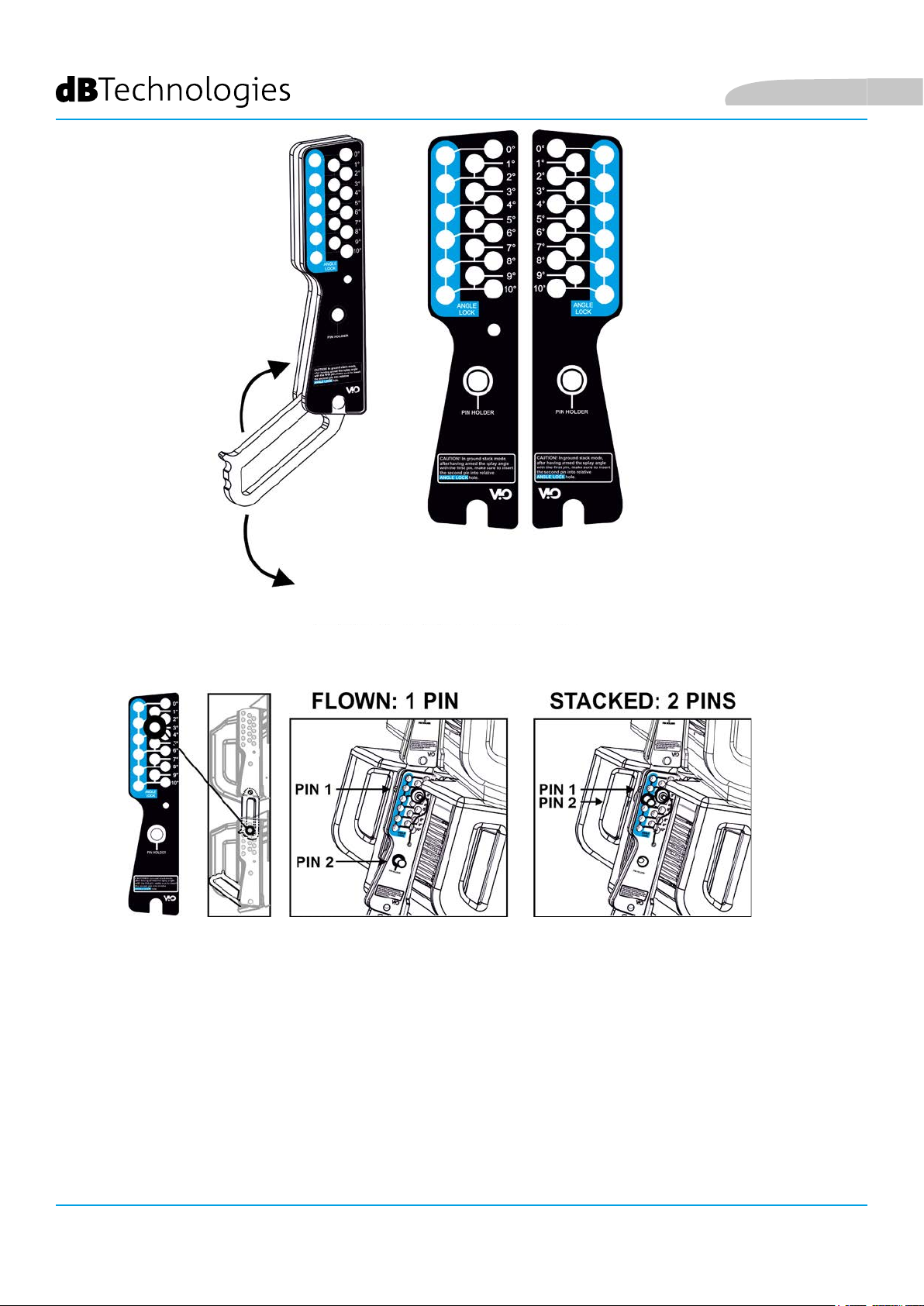
Français
ATTENTION ! EXEMPLE : 3°
L’exemple montre le cas où on voudrait positionner les 2 modules avec un angle de 3°.
Avant toute autre opération vérier que, après avoir inséré le bras mobile [6], le trou de l’angle choisi résulte
contenu à l’intérieur de la fente comme indiqué.
• POSITIONNEMENT FLOWN : introduire 1 seul goujon dans le trou correspondant dans l’angle choisi. Le deuxième
goujon doit être logé dans le trou « PIN HOLDER ». Il est à noter que ce type de conguration en cours de montage
permet de changer l’angle choisi simplement en déplaçant le goujon relatif (lorsque le bras mobile est inséré).
• POSITIONNEMENT STACKED : après avoir introduit le goujon [5] dans le trou de l’angle choisi, soulever le module B
tant que le bras mobile [6] le permet. À ce stade, introduire le deuxième goujon dans la position « ANGLE LOCK »
et relâcher le module B. De cette façon le module B résulte complètement bloqué sur l’arrière grâce aux 2 goujons.
Toujours s’assurer à la n du montage que tous les goujons ont été insérés complètement et qu’ils résultent
bloqués.
VIO-L210
Code 420120248 RÉV. 1.1
96
Page 97
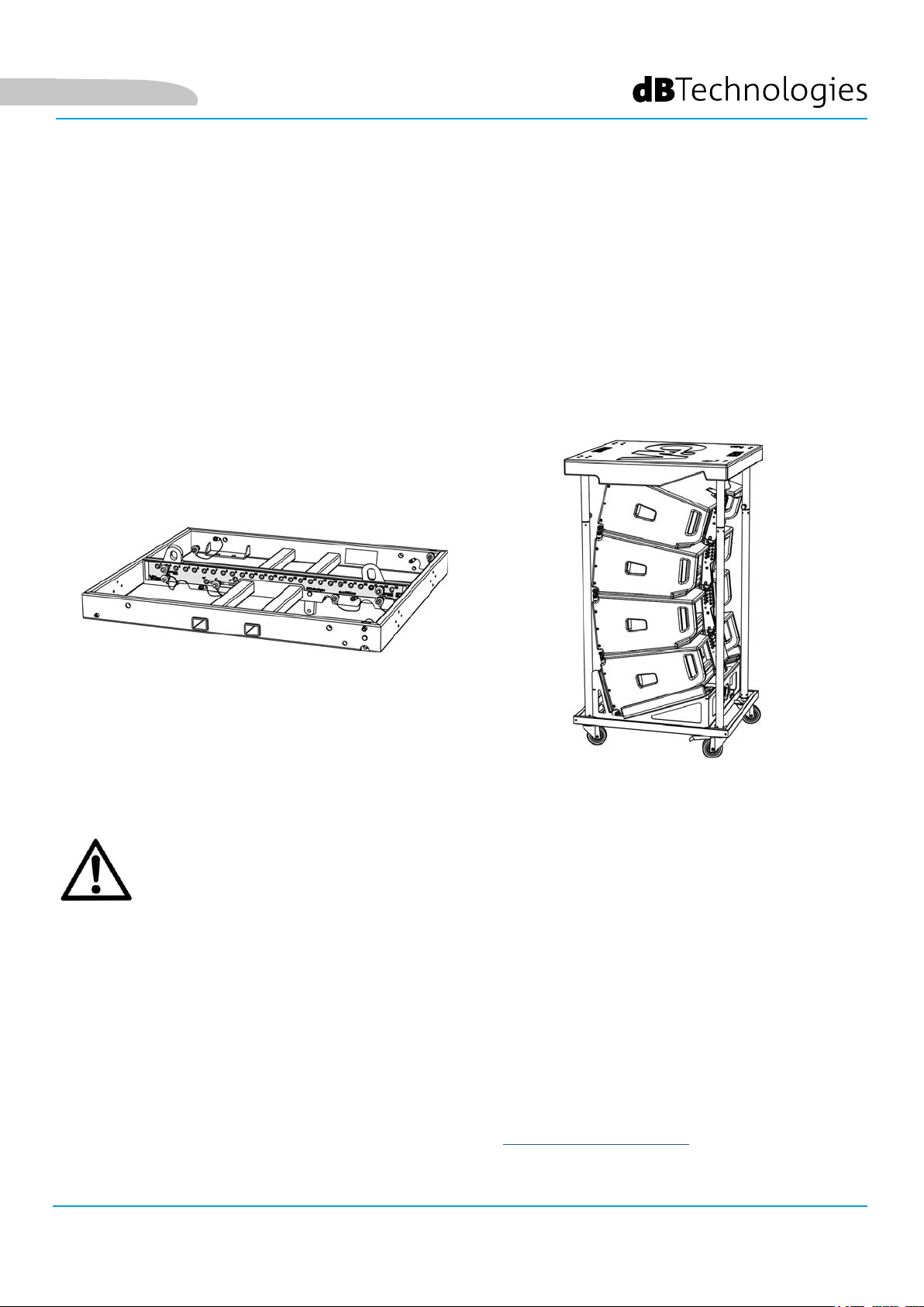
Français
ACCESSOIRES
Pour une installation rapide, on prévoit les accessoires suivants en option :
• DRK-210, y-bar pour l’utilisation en conguration own et stacked des line array de modules
VIO-L210.
• DT-VIOL210, chariot pour transporter jusqu’à 4 modules VIO-L210. Grâce à cet accessoire, il est possible
de monter sur le couvercle, exclusivement pour le transport, 1 y-bar DRK-210.
DRK-210
DT-VIOL210
ATTENTION !
• Utiliser uniquement les accessoires et les congurations indiqués dans le présent manuel et opérer
conformément à ce qui est indiqué dans les manuels correspondant aux accessoires.
• DRK-210 a été conçu pour suspendre jusqu’à 25 VIO L210 (ou bien 16 modules Sub) pour un poids
maximum de 750 kg avec un seul point d’ancrage.
Les composants de suspension de VIO L210 permettent de connecter jusqu’à 10 modules (max
300 kg) sans limites sur l’angle du line array. Toute autre conguration ou information sur les
données du système, comme la charge maximale et les points d’ancrage, doit être vériée avant
l’installation à l’aide du logiciel dBTechnologies Composer (voir le paragraphe relatif dans ce
manuel d’utilisation). Il est disponible gratuitement sur le site www.dbtechnologies.com dans la
section DOWNLOAD.
Pour toute information complémentaire, se référer aux manuels relatifs.
Pour toutes les mises à jour sur les accessoires consulter le site www.dbtechnologies.com
VIO-L210 Code 420120248 RÉV. 1.1
97
Page 98
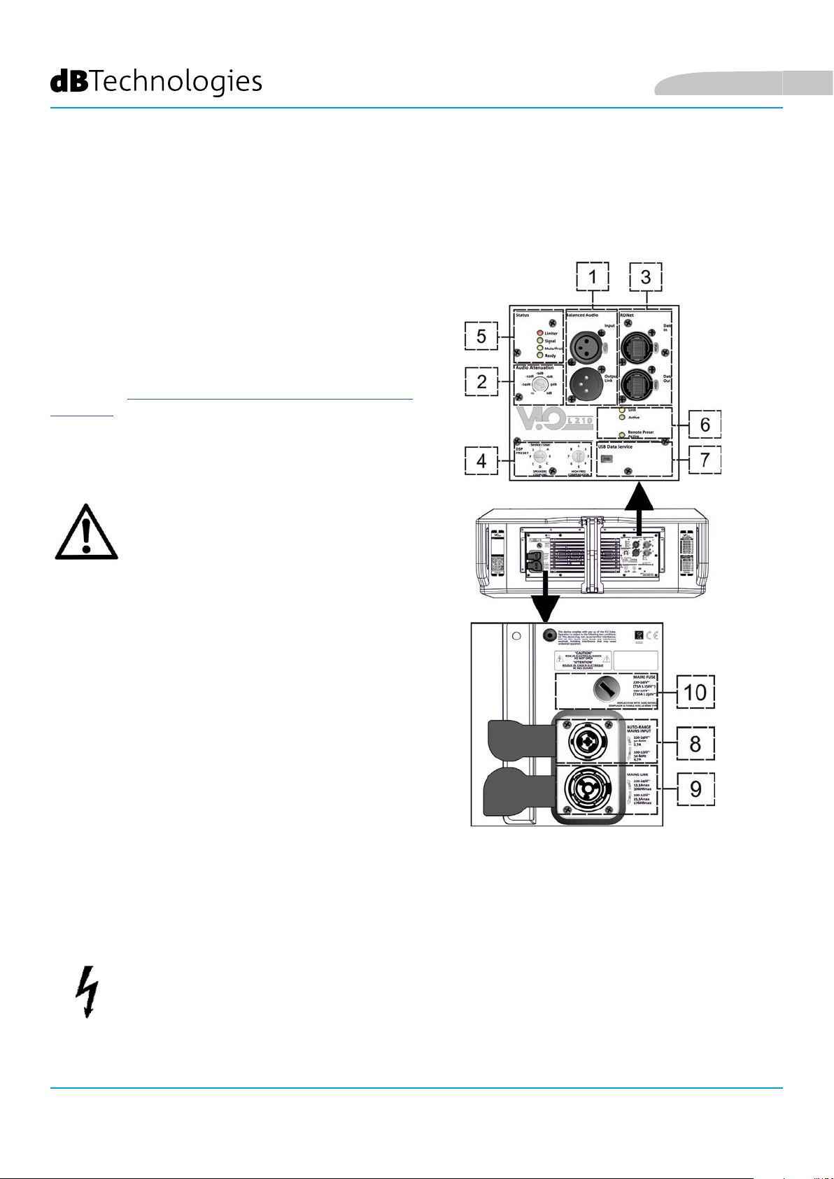
Français
CARACTÉRISTIQUES DE LA SECTION D'AMPLIFICATION ET DE CONTRÔLE
L'amplicateur numérique, classe D, est le cœur des modules
VIO-L210.
Il permet de débiter jusqu’à 900 W RMS, de manière silencieuse
et efcace ne nécessitant pas d’un système de ventilation. Le
contrôle du système est coné à un DSP puissant qui rend
possible la conguration immédiate et rapide du
line-array dans n’importe quel contexte d’utilisation.
Grâce à la possibilité de connexion au réseau via RDNet, les
paramètres sur le panneau peuvent être contrôlés à distance,
grâce au logiciel « DBTECHNOLOGIES NETWORK » (voir le
paragraphe PARAMÈTRES DSP PRESET ET COMMANDE À
DISTANCE).
Le panneau du DIGIPRO G3 est caractérisé par :
• Section d’Entrée de Sortie et de Contrôle
• Section d’Alimentation
ATTENTION !
• Ne pas obstruer les ailettes arrière de
refroidissement de l’amplicateur. En cas de
surchauffe excessive, le volume audio est
réduit progressivement jusqu’à la stabilisation
thermique du module. Le niveau est rétabli
automatiquement lorsque la température
correcte de fonctionnement à été atteinte.
• N'essayer en aucun cas d'ouvrir l'amplicateur.
• En cas de dysfonctionnement, couper
immédiatement l'alimentation et débrancher le
module du réseau, puis contacter un réparateur
agréé.
SECTION
CONTRÔLE
D’ENTRÉE, SORTIE ET
VIO-L210
98
• Utiliser de préférence des câbles dotés de
connecteurs d’origine Neutrik®, de haute
qualité. En contrôler périodiquement l’intégrité.
• L’enceinte est livrée avec un fusible déjà monté
pour fonctionner dans la plage 220-240 V. S’il est
nécessaire de travailler dans la plage de tension
100-120 V :
1. Débrancher toutes les connexions, y
compris l'alimentation.
2. Attendre 5 minutes.
3. Remplacer le fusible par celui fourni
dans l'emballage pour la plage 100-120 V.
ATTENTION !
• Ne jamais démonter la grille frontale de protection du produit.
Pour prévenir le danger de choc électrique, en cas d’endommagement accidentel ou de remplacement de la grille de protection (à effectuer auprès du service assistance) , couper immédiatement
l’alimentation.
Ne jamais brancher l’alimentation secteur avec la grille démontée.
Code 420120248 RÉV. 1.1
SECTION
ALIMENTATION
Page 99
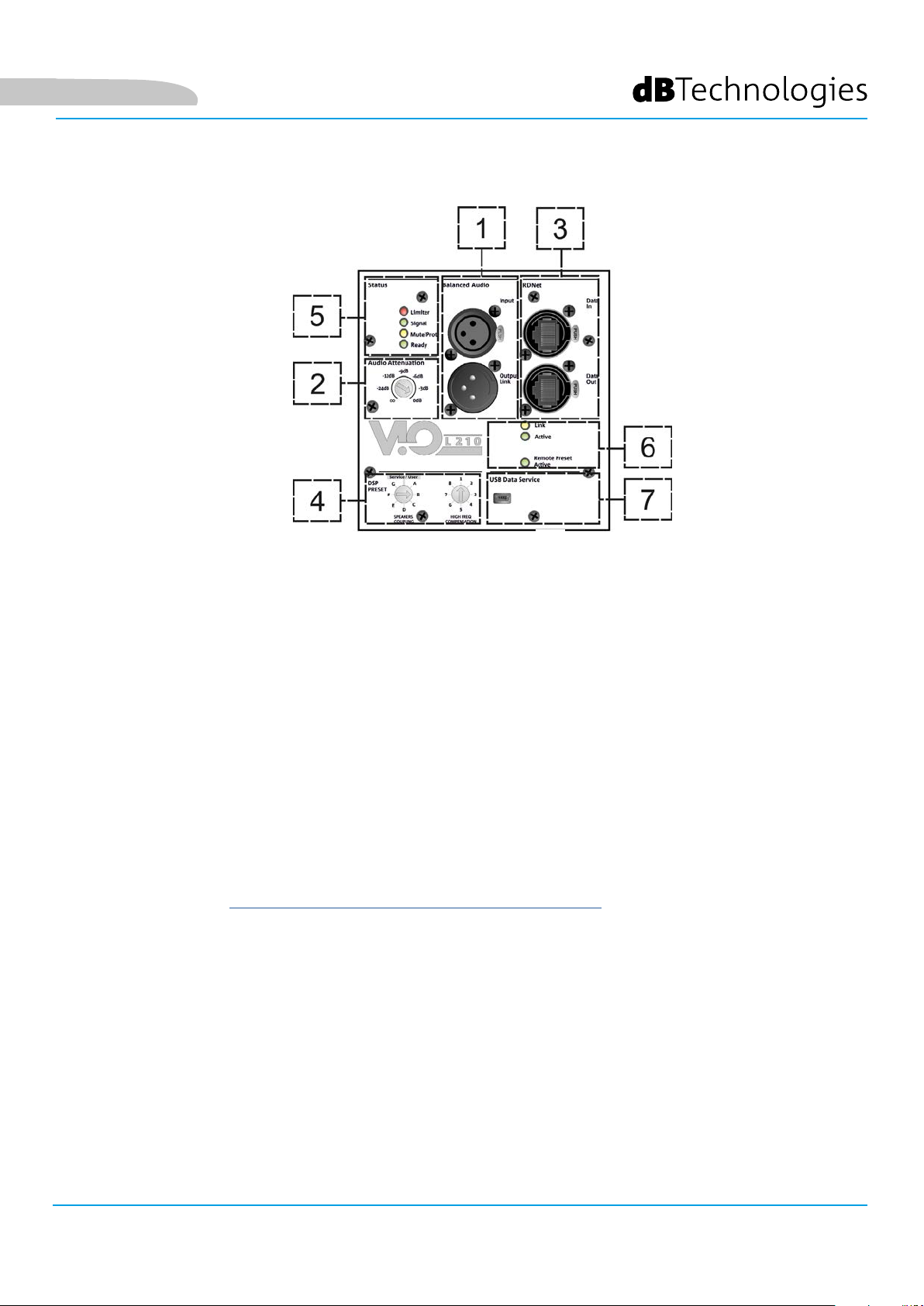
Français
SECTION D'ENTRÉE, DE SORTIE ET DE CONTRÔLE
1. ENTRÉE ET RELANCE AUDIO (« Balanced audio »)
Entrée et sortie compatible avec câbles XLR symétriques.
En particulier, « Input » est utilisé pour le branchement avec le signal audio venant du mélangeur ou d’une autre
enceinte, « Output Link » pour la relance du signal aux autres modules du line-array en conguration daisy-chain.
2. AUDIO ATTENUATION
Elle permet de régler l’atténuation du module en agissant sur le volume d’entrée.
Régler à 0 dB avant de commencer le montage du line-array.
3. ENTRÉE ET RELANCE DE LA CONNEXION DE RÉSEAU RDNet
Section compatible avec les câbles de réseau avec connecteurs type etherCON/RJ45.
En particulier « Data in » doit être relié à des dispositifs comme RDNet Control 2 ou Control 8, « Data Out » est
utilisé pour la relance du réseau à d’autres modules du line-array en conguration daisy-chain.
4. DSP PRESET
Commande rotative pour le réglage acoustique du line-array.
Il convient d’utiliser ces commandes (ou les mêmes paramètres à distance avec la connexion RDNet)
pour optimiser la performance acoustique en fonction du nombre de modules et à leur pointage. Un
approfondissement sur l’utilisation de « SPEAKER COUPLING » et « HIGH FREQUENCY COMPENSATION » est
présent dans la section «PARAMÈTRES DSP PRESET ET CONTRÔLE À DISTANCE”.
5. LED D’ÉTAT
LED relatives au fonctionnement du module. Un tableau dans la page suivante résume et synthétise la fonction
des différentes LED.
6. LED DE CONTRÔLE
LED relatives au fonctionnement en réseau (RDNet) du module.
En particulier, « Link » allumé signale que le réseau RDNet est actif et a reconnu le dispositif, « Active » en mode
clignotant, qu’il existe un trac de données, « Remote Preset Active » que toutes les commandes locales sur le
panneau amplicateur sont by-passées par la commande à distance RDNet.
7. USB DATA SERVICE
Port de type mini-USB B, à utiliser exclusivement pour la mise à jour du micrologiciel du produit. Voir la section
« MISE À JOUR DU MICROLOGICIEL » pour plus d’informations.
VIO-L210 Code 420120248 RÉV. 1.1
99
Page 100

Français
TYPE LED PHASE D’ALLUMAGE
DE L'ENCEINTE
EN FONCTION
NORMALE
MISE EN GARDE
GÉNÉRIQUE
BLOCAGE POUR
ANOMALIE DE
L’ENCEINTE
LIMITER ÉTEINT ÉTEINT, IL
S’ALLUME
SEULEMENT
EN CAS
D’INTERVENTION
SIGNAL
SOURDINE/
PROT
PRÊT ÉTEINT ALLUMÉ FIXE ALLUMÉ FIXE ÉTEINT
ÉTEINT CLIGNOTEMENT
EN PRÉSENCE DE
SIGNAL
ALLUMÉ PENDANT
QUELQUES SECONDES
ÉTEINT CLIGNOTEMENT
Tableau de signalisation des LED d’état
CLIGNOTEMENT
MOMENTANÉ
SIGNALISATION
NORMALE D’AUDIO
EN ENTRÉE
MOMENTANÉ
CLIGNOTEMENT
CYCLIQUE CONTINU
ÉTEINT
ALLUMÉ FIXE
SECTION D'ALIMENTATION
8. CONNECTEUR D'ALIMENTATION « MAINS INPUT »
Compatible avec le connecteur powerCON TRUE1®, l’alimentation est dotée de fonction autorange. Après avoir
déni la plage opportune avec le remplacement éventuel du fusible, il reconnaît automatiquement la tension à
l’intérieur de la plage [100-120V~] ou bien [220-240V~].
9. RELANCE D'ALIMENTATION « MAINS INPUT »
Compatible avec connecteur type powerCON TRUE1® pour la relance de l’alimentation à d’autres modules.
Pour savoir le nombre maximum de modules pouvant être connectés dans un système relancé, consulter la
section SPÉCIFICATIONS TECHNIQUES.
10. FUSIBLE DE RÉSEAU.
Logement pour le fusible de réseau.
VIO-L210
Code 420120248 RÉV. 1.1
100
 Loading...