

Page 1
www.dbtechnologies.com info@dbtechnologies-aeb.com
Quick start user manual
Section 1
The warnings in this manual must be observed together with the "USER MANUAL - Section 2".
Le avvertenze nel presente manuale devono essere osservate congiuntamente al “MANUALE D’USO - Sezione2”.
Die Warnungen in diesem Handbuch müssen in Verbindung mit der "BEDIENUNGSANLEITUNG - Abschnitt 2" beobachtet
werden”.
Les avertissements specifiés dans ce manuel doivent être respectés ainsi que les "CARACTERISTIQUES TECHNIQUES Section 2"
Las advertencias del presente manual se deben tener en cuenta conjuntamente con las del “MANUAL DEL USUARIO” Sección 2”.
A.E.B. Industriale Srl Via Brodolini, 8 Località Crespellano 40053 VALSAMOGGIA BOLOGNA (ITALIA)
Tel +39 051 969870 Fax +39 051 969725 www.dbtechnologies.com info@dbtechnologies-aeb.com
VIO L208 cod. 420120268Q rev.1.1
Page 2
www.dbtechnologies.com info@dbtechnologies-aeb.com
Thank you for choosing a dBTechnologies Product!
VIO L208 is the new dBTechnologies flagship 2-way professional active line array module. It is equipped with: one
1.4” neodymium compression driver exit (2.5” neodymium voice coil) and two 8” neodymium woofers (2” voice coil).
The full-range acoustical design includes an efficient all-in-one panel with phase corrector, in order to reach the best
coherence in line-array configuration. The mechanical design allows an easy, accurate and quick installation in flown
or stack use. The powerful DIGIPRO® G3 amplifier section, capable of handling up to 900 W (RMS power), is
controlled by a DSP, which can perform a detailed customization of the output sound of the speaker. In particular,
thanks to the dual rotary encoder interface, it is possible to accurately tune the line-array configuration coverage,
using the FIR filter technology. In addition, the integrated RDNET connections are useful for a remote in-depth linearray control and configuration.
Check the site www.dbtechnologies.com for the complete user manual!
1) Unpacking
The box contains:
N°1 VIO L208
N°1 100-120 V FUSE
In order to mount the line array, for each module:
This quick start and warranty documentation
2) Easy installation
VIO L208 can be installed in different configurations.
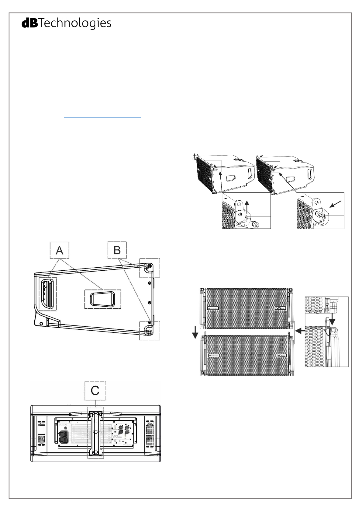
For a quick installation, in each side of the
loudspeakers the user can find:
- Central and rear handles for easy handling (A)
- Two quick-release pin connections for frontal
mounting (B), with upper integrated front arms.
- Remove the upper front pins and lift the front arms
in the final position as shown.
- Fasten the arms with the pins in the lower holes.
In the rear side the user can find:
- One rear bracket (C) (with movable arm) for linearray mounting, with splay angles reference holes for
easy setup and two quick-release pins.
- Put a second VIO L208 and remove the lower
frontal pins.
- Put this second enclosure on the top of the first.
- Insert the front arms in the position shown, aligning
the related holes.
VIO L208 2 cod. 420120268Q rev.1.1
Page 3
www.dbtechnologies.com info@dbtechnologies-aeb.com
- Fasten the two enclosures using the quick-release
pins of the upper VIO L208.
- Check that all the pins are properly inserted and
locked before other mounting steps.
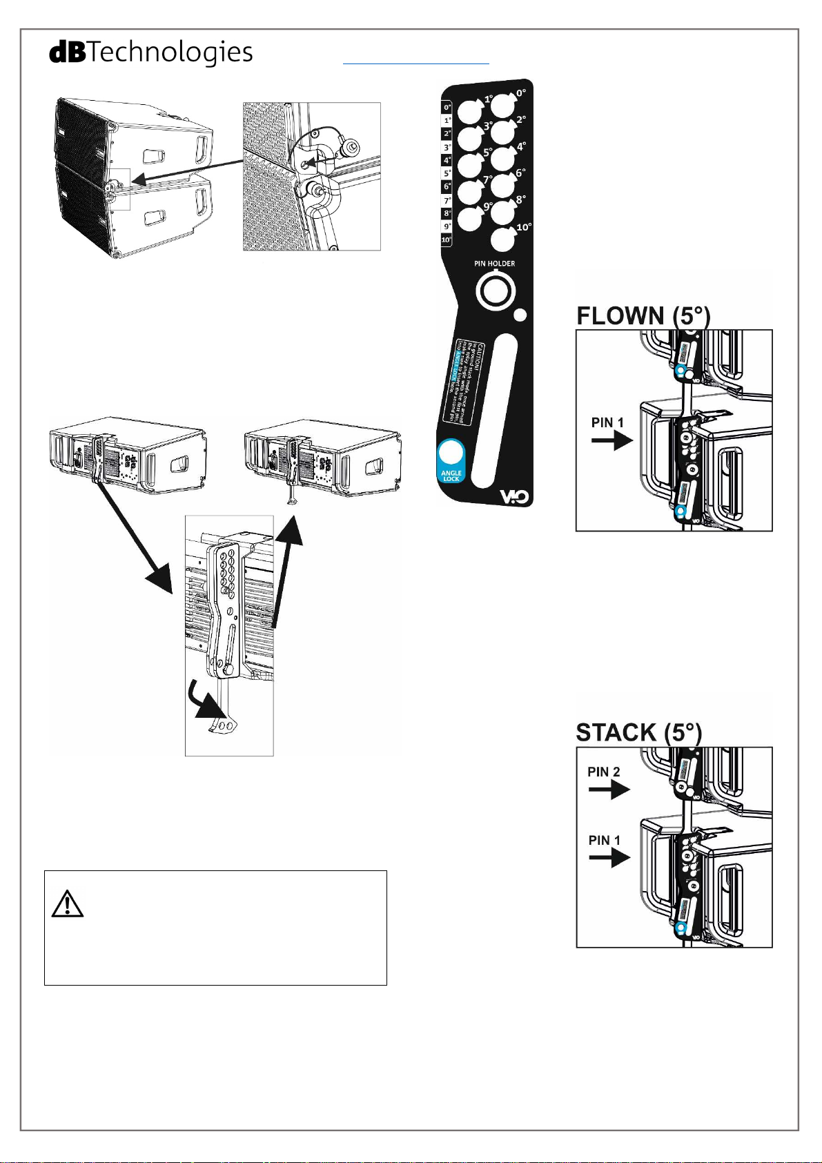
- Insert the movable arm of rear
bracket of the upper enclosure into
the related housing of the lower one.
- Choose the desired splay angle
between the two enclosures.
- If you need a flown installation, only one pin is
required to secure the movable arm. Check that the
arm is inserted in the bracket. Lift the arm (not the
entire VIO-L208 module) to the desired tilt hole. Fasten
one of the two rear pins in the desired angle, and let
the second one in the position “PIN HOLDER”. Check
that the pins are fully inserted.
- If you need a
stacked installation,
- Remove the rear pins and put the swing rear
bracket in the final position as shown.
CHECK PERIODICALLY THE INTEGRITY AND THE
FUNCTIONALITY OF THE ENCLOSURE, OF THE
PINS AND OF THE BRACKETS, FOR A SAFE
INSTALLATION. MAKE SURE THAT THE PINS SECURE
PROPERLY THE MODULES AND THAT THEY ARE FULLY
LOCKED.
it is mandatory to
use two pins (of 2
different modules)
to secure the rear
bracket. Check that
the arm is fully
inserted in the
bracket. Lift the arm
(not the entire VIO-L
208 module) to the
desired tilt hole and
insert the PIN 1 in to
the related splay angle position. Then lift the VIO-L208
upper module, until you can insert the PIN 2 in the
“ANGLE LOCK” position as shown. Release the upper
enclosure and check that the movable arm leans on the
second pin, fastened in the correct position.
VIO L208 3 cod. 420120268Q rev.1.1
Page 4

www.dbtechnologies.com info@dbtechnologies-aeb.com
3) Accessories
For an easy setup are available among others: a
professional fly-bar (DRK-208) for flown installation,
an adapter (TF-VIO1) for the mounting with VIO-L210,
a stack (and flown) frame to adapt to VIO-S118, and a
trolley (DT-VIOL208) for a quick and safe transport.
DRK-208
The DRK-208 fly-bar allows flown configuration, for the
professional use. It has one rear arm [X] and 2 pins [Y]
for the mounting. A [W] optional bracket, if needed,
allows using a laser inclinometer (not supplied). The
maximum admitted number of cabinets in different
configurations depends on various parameters, like
VIO L208 splay angles and DRK-208 tilt. The free
dBTechnologies Composer (form version 6.4) software
helps the user in the right choice for the best
mechanical and acoustical result.
AF-VIO1
DSA-VIOL208
In stacked installation on a VIO-S118, for example,
the AF-VIO1 must be used as illustrated. This
versatile accessory is useful also in different
scenarios (flown, adapting to VIO-L210s). For further
and detailed information please refer to the related
AF-VIO1 user manual. DSA-VIOL208 is designed for
pole-mount application, as shown in the picture.
The DT-VIOL208 trolley can carry up to four VIO L208s.
It has been designed for a quick displacement of the
line-array elements. It is provided with wheels with
brakes to protect the loudspeakers in a safe and
ergonomic way. It can carry also 1 DRK-208, as shown.
CART-VIO-L208
For further and detailed information please refer
to the related DT-VIOL208 user manual.
CHECK PERIODICALLY THE INTEGRITY AND
THE FUNCTIONALITY OF THE ACCESSORIES
AND OF THE TECHNICAL EQUIPMENTS FOR A
TF-VIO1
The TF-VIO1 allows combining VIO-L208 under VIOL210 modules in line-array installations.
SAFE INSTALLATION. USER SHOULD NEVER APPLY A
LOAD THAT EXCEEDS THE WORKING LOAD LIMITS OF
ANY RIGGING COMPONENTS OR EQUIPMENT HERE
PRESENTED. DESIGN, CALCULATION, INSTALLATION,
TESTING AND MAINTAINANCE OF SUSPENSION AND
STACK SYSTEMS FOR AUDIO EQUIPMENT MUST BE
PERFORMED ONLY BY QUALIFIED AND AUTHORIZED
PERSONNEL, USING THE SOFTWARE
DBTECHNOLOGIES COMPOSER. AEB INDUSTRIALE
S.R.L. DENIES ANY AND ALL RESPONSIBILITY FOR
IMPROPER INSTALLATIONS, IN THE ABSENCE OF
SAFETY REQUIREMENTS.
VIO L208 4 cod. 420120268Q rev.1.1
Page 5

www.dbtechnologies.com info@dbtechnologies-aeb.com
4) First switch on for line-array setup
The DIGIPRO G3® amplifier of VIO L208 is controlled
by a powerful DSP. All the connections and controls
are in the rear amplifier control panel:
1 – Balanced audio input and output link
2 – Audio Attenuation rotary switch
3 – RDNet Data In / Data out
4 – DSP PRESET rotary switches (Speaker
coupling/High frequency compensation)
5 – Status LEDs (Limiter, Signal, Mute/Protection,
Ready)
6 – Control LEDs (Link, Active, Remote preset Active)
7 – Mini B-type USB port for firmware updating
8 – Auto-range Mains Input
9 – Mains link output
10 –Mains fuse
WARNING
The fuse is factory set for 220-240V~ operation.
If it is necessary to change the fuse to 100-120V~ range:
1. Turn off the power and disconnect the speaker from
any cable.
2. Wait 5 minutes.
3. Substitute the fuse with the correct one supplied.
a) Once you have properly set up the mechanical
line-array configuration (see also the VIO L208
complete user manual and accessories instructions for
further information), connect the audio input (1) of the
first module of the array. Then connect the useful link
audio output (1) to other VIO L208 modules, for the
connection of all the line-array elements. Set the Audio
Attenuation (2) of the loudspeakers to 0 dB.
b) Check the rear panel
reference label for a proper DSP
regulation in line array. Please
note that this kind of
configuration can be set and
modified also by the use of
remote controller (RDNet
Control 2 or RDNet Control 8)
and software (Aurora,
dBTechnologies Network, from
3.4 version). For this information
see the chapter 5.
In this rear label (“SUGGESTED
CONFIGURATIONS”) you can
find the suggested position of
rotary switches (4) for each type
of installation (Speakers
Coupling positions and High
Frequency Compensation).
These settings are the main
acoustic corrections to create
the proper coupling between
the elements of your line-array,
in order to obtain the best
coverage conditions.
In particular, the “SPEAKER
COUPLING” rotary acts mainly
on low frequencies, and it can
be set in 6 positions, depending on the number of
elements of line-array.
VIO L208 5 cod. 420120268Q rev.1.1
Page 6

www.dbtechnologies.com info@dbtechnologies-aeb.com
A seventh “Bass boost” position assign particular
emphasis on the lower frequencies. The “service/user”
one allows USB port communication for firmware
updating (or can recall on the speaker user settings
previously saved in remote control with
dBTechnologies Network). The “HIGH FREQUENCY
COMPENSATION” can act on medium-high
frequencies. The user can choose among a “FLAT”
position (which give a flat equalization in this
frequencies band), and other 7 positions, depending
on the distance between the line-array and the
audience (in meters and feet).
c) Connect the power link output (9) of the first
module to the mains input (8) of a second VIO L208
module of the line-array, and so on, in order to link
the power supply between all the elements. The
maximum linkable rated power and current depends
on the first module connection (type of cable, type of
connector used). The plate data give information
about the entire linked line-array system. The
maximum number of modules for each power daisy
chain connection [mains input + mains link] is: 1+5
VIO L208s** at 220-240V~, and 1+3 VIO L208s** at
100-120V~ (for further information see Technical
Data).
d) In case of remote control, connect the proper
Data Input (3) of the first module of the line-array to
the hardware remote controller (RDNet Control 2 or
RDNet Control 8) with cables equipped with etherCON
connectors. Then connect the Data Output (3) of the
first module to the Data Input (3) of the second one,
and so on. When the RDNet network is on and it has
recognized the connected device, the LED “Link” (6) is
on. The other LED (6) “Active” start blinking when
there is the presence of data transmission, the
“Remote Preset Active” advise that all the local
controls set on the amplifier panel (level, DSP presets,
etc.) are by-passed and controlled remotely by RDNet.
See also RDNet Control 2 and RDNet Control 8 user
manuals for further information.
e) Connect the power supply (8) to the first
module. The related “Ready” LED (5) turns on,
signaling the proper power connection. The “Signal”
LED (5) start blinking at the presence of audio signal
(greater than -20dBu). Avoid audio distortion
conditions, potentially signaled by the “Limiter” LED
(5).
IN FLOWN CONFIGURATION, IT IS ADVISABLE
TO START ALL THE CONNECTIONS FROM THE
TOP (“FIRST ELEMENT”) OF THE LINE-ARRAY,
FOR THE BEST CABLING, IN ACCORDANCE WITH THE
FOLLOWING SCREENS OF “DBTECHNOLOGIES
NETWORK” SOFTWARE.
5) Software (Aurora, dBTechnologies Network and
dBTechnologies Composer)
VIO L208 can be fully remote controlled via RDNet.
The connection details have been illustrated in the
chapter 4 (“d” point). In remote control mode, the
use of free professional software, developed by
dBTechnologies, allows a complete system
management: Aurora Net, dBTechnologies Network.
dBTechnologies Composer is a predictive software
for the design and the check of acoustical and
mechanical settings. They can be downloaded for
free from the official site:
www.dbtechnologies.com/EN/Downloads.aspx
Check always for software updates!
a) Aurora Net
The software which must be used in case of remote
control is Aurora Net. This cross-platform product
allows the user controlling, setting and organizing all
the ViO family. It also fully supports DANTE audio
networking. Check the site www.dbtechnologies.com
for further information.
b) dBTechnologies Network
A second
software which
must be used in
case of remote
control is
dBTechnologies
Network (from
the version no.
3.4). This
software can
control different
speakers in
different
configurations.
It allows a
complete remote
control and a full
real-time
monitoring in
various scenarios. For example, the user can control a
setup with 2 line-arrays of VIO L208 and 3 VIO S118
subwoofers, and change different parameters while
the entire system is sounding.
It can also offer a deeper loudspeaker control than the
simple rear amplifier panel rotaries.
VIO L208 6 cod. 420120268Q rev.1.1
Page 7

www.dbtechnologies.com info@dbtechnologies-aeb.com
Those VIO L208 parameters can be controlled by
using dBTechnologies Network:
- MUTE/SOLO switch*
- INPUT ATTENUATION
- SPEAKERS COUPLING
- HIGH FREQUENCY COMPENSATION
- HPF FILTER PRESET*
- DELAY*
The * parameters can be controlled only via
software.
LAST SETTINGS STORED ON VIOL208 (USING
DBTECHNOLOGIES NETWORK SOFTWARE),
CAN BE RECALLED LATER ON THE SPEAKER,
WITHOUT RDNET REMOTE CONTROL: SIMPLY TURN THE
ROTARY “SPEAKER COUPLING” ON “SERVICE/USER”
POSITION.
c) dBTechnologies Composer
The software dBTechnologies Composer (from
version no. 6.4) is useful for complete sound
systems design. It has been developed to optimize
complex acoustical settings like line-array alignment
and to calculate easily all parameters needed in
professional sound system scenarios.
It is used to predict completely the acoustical
behaviour of professional dBTechnologies products
in an immediate way.
In particular, it can simulate different parameters,
for example: mechanical safety in fly-bar use, SPL
levels in outdoor environment, system coverage,
system delays. The user-friendly graphic interface
helps the user to easily understand in-depth
settings.
Check the complete user manual on www.dbtechnologies.com
for further information about the system and available
accessories.
Scarica il manuale completo da www.dbtechnologies.com per
ogni ulteriore informazione sul sistema e sugli accessori
disponibili.
Für weitere Informationen und verfügbares Zubehör lesen sie
bitte die vollständige Bedienungsanleitung unter
www.dbtechnologies.com.
Vérifiez le manuel de l'utilisateur complet sur
www.dbtechnologies.com pour des informations
complémentaires du système et des accessoires disponibles.
Compruebe el manual de usuario completo sobre
www.dbtechnologies.com para la información adicional sobre el
sistema y accesorios disponibles.
VIO L208 7 cod. 420120268Q rev.1.1
Page 8

www.dbtechnologies.com info@dbtechnologies-aeb.com
Technical Data
Speaker Type: 2-way professional active line-array
element
Acoustical data
Usable Bandwidth [-6 dB]: 75 – 20000 Hz
Frequency Response [±3dB]: 85 – 18100 Hz
Max SPL (1 m): 133.5 dB
HF compression driver: 1.4" Exit, Neodymium
HF voice coil: 2.5”, Neodymium
Waveguide HF: yes
LF: (2x) 8”, Neodymium
LF Voice Coil: 2”
LF Phase plug: All in one panel with phase corrector
Crossover frequency: 1000 Hz
FIR filters: yes
Horizontal dispersion ([-6dB] 500 – 18100 Hz): 100°
Vertical dispersion: varies on number of modules and
configurations
Amplifier
Amp Technology: Digipro® G3 - Autorange
Amp Class: Class-D
RMS Power: 900 W
Peak Power: 1800 W
Cooling: Passive (convection)
Operating range:
Temperature range:
220-240V~ (50-60Hz)/100-120V~ (50-60 Hz)
-15 +55 [°C]
Processor
Controller: DSP, 28/56 bit 48 kHz
Limiter: Dual Active Peak, RMS, Thermal
Controls: Audio attenuation, DSP presets
Advanced DSP function: Linear Phase FIR filters
Rotary presets: 2 Rotary BCD 8 positions for line-array
configuration (Speaker Coupling, High Frequency
Compensation)
Input / Output
Mains connections: PowerCON® TRUE1 In / Link
Maximum number of modules for each daisy chain
power connection [mains input + mains link]: 1+5 VIO
L208** (220-240v~), 1+3 VIO L208** (100-120V~)
Signal Input: (Balanced) 1x XLR IN
Signal Out: (Balanced) 1 x XLR link OUT
RDNET connectors: Data In / Data Out
USB connector: mini USB B-type (for SERVICE DATA)
Mechanics
Housing: Wooden box – Black polyurea finished
Grille: CNC machined full metal grille
Rigging points: 3 (Easy Rigging)
Handles: 2 side handles + 2 wooden handles
(integrated)
Width: 600 mm (25.98 in)
Height: 260 mm (10.24 in)
Depth: 390 mm (15.35 in)
Weight: 18.1 kg (39.9 lbs.)
Scan with your QR
Reader App to
download the
complete User
Manual
Download the complete user manual on:
www.dbtechnologies.com/EN/Downloads.aspx
EMI CLASSIFICATION
According to the standards EN 55103 this equipment is designed and suitable to operate in E3 (or lower E2, E1) Electromagnetic environments.
FCC CLASS B STATEMENT ACCORDING TO TITLE 47, PART 15, SUBPART B, §15.105
This equipment has been tested and found to comply with the limits for a Class B digital device, pursuant to part 15 of the FCC Rules.
These limits are designed to provide reasonable protection against harmful interference in a residential installation.
This equipment generates, uses and can radiate radio frequency energy and, if not installed and used in accordance with the instructions, may cause harmful
interference to radio communications.
However, there is no guarantee that interference will not occur in a particular installation. If this equipment does cause harmful interference to radio or television
reception, which can be determined by turning the equipment off and on, the user is encouraged to try to correct the interference by one or more of the following
measures:
1. Reorient or relocate the receiving antenna.
2. Increase the separation between the equipment and receiver.
3. Connect the equipment into an outlet on a circuit different from that to which the receiver is connected.
4. Consult the dealer or an experienced radio/TV technician for help.
Changes or modifications not expressly approved by the party responsible for compliance could void the user’s authority to operate the equipment.
WARNING: Make sure that the loudspeaker is securely installed in a stable position to avoid any injuries or damages to persons or properties. For safety reasons
do not place one loudspeaker on top of another without proper fastening systems. Before hanging the loudspeaker check all the components for damages,
deformations, missing or damaged parts that may compromise safety during installation. If you use the loudspeakers outdoor avoid spots exposed to bad weather
conditions.
Contact dB Technologies for accessories to be used with speakers. dBTechnologies will not accept any responsibility for damages caused by inappropriate accessories
or additional devices.
Features, specification and appearance of products are subject to change without notice.
dBTechnologies reserves the right to make changes or improvements in design or manufacturing without assuming any obligation to change
or improve products previously manufactured.
VIO L208 cod. 420120268Q rev.1.1
 Loading...