

Page 1
ISTRUZIONI DI UTILIZZO AF-VIO1
AF-VIO1 INSTRUCTIONS
AF-VIO1
Accessorio
Accessory
Prodotto
Product
AF-VIO1 VIO-L208-VIO-L210
VIO S118 / S118R / S218 / S318
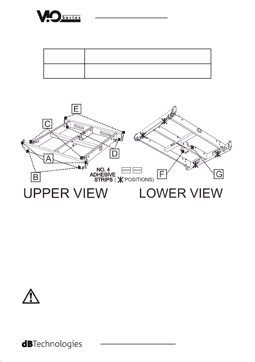
1.Contenuto della confezione
Packing content
A - n°2 AGGANCI SUPERIORI PER VIO-L210 / VIO-S118
n°2 UPPER ANCHORAGE SYSTEMS FOR VIO-L210/ S118
B - n°2 AGGANCI FRONTALI CON PIN PER VIO-L208
n°2 FRONT ANCHORAGE SYSTEMS FOR VIO-L208
C - n°2 STAFFE RETRAIBILI PER INSTALLAZIONE STACK (VIO-L208)
n°2 RETRACTABLE BRACKETS FOR STACK INSTALLATION (VIO-L208)
D - n°2 STAFFE DI AGGANCIO A SUBWOOFER IN STACK
n°2 BRACKETS FOR FASTENING TO A SUBWOOFER IN STACK
E - n°1 AGGANCI POSTERIORI PER VIO-S118 (FLOWN)
n°1 REAR ANCHORAGE SYSTEMS FOR VIO-S118 (FLOWN)
F - n°1 GIUNTO MOBILE PER INSTALLAZIONE FLOWN
n°1 MOBILE JOINT FOR FLOWN INSTALLATION
G - n°1 SEDE DI AGGANCIO POSTERIORE IN STACK
n°1 HOUSING FOR THE REAR FASTENING IN STACK
L’installazione di AF-VIO1 deve essere effettuata da personale esperto. I tipi di utilizzo ammessi sono 3 e sono
illustrati qui di seguito. Non sono ammessi utilizzi differenti da quanto descritto. A pagina 4 sono anche riportati
i limiti massimi per installazione stack libera. Se si eccedono tali limiti è obbligatorio un ssaggio addizionale
con cinghie o mezzi meccanici (non forniti). Per congurazioni che eccedano questi limiti, è obbligatorio un
ssaggio addizionale con cinghie o mezzi meccanici non forniti. I limiti own sono determinati dall’utilizzo di
dBTechnologies Composer.
Only qualied personnel may use the AF-VIO1! The admitted uses are 3 and they are illustrated in the next
pages. Different uses are not allowed. The maximum limit in stack installation is shown in the table at page 4.
If you need to exceed those limits it is mandatory to use additional mechanical systems and fastening belts (not
supplied). For congurations that exceed those limits, it is mandatory the use of a fastening system with straps
or mechanical means (not supplied). The own maximum limits are calculated with dBTechnologies Composer.
FOT000100 REV.1.1
Page 2
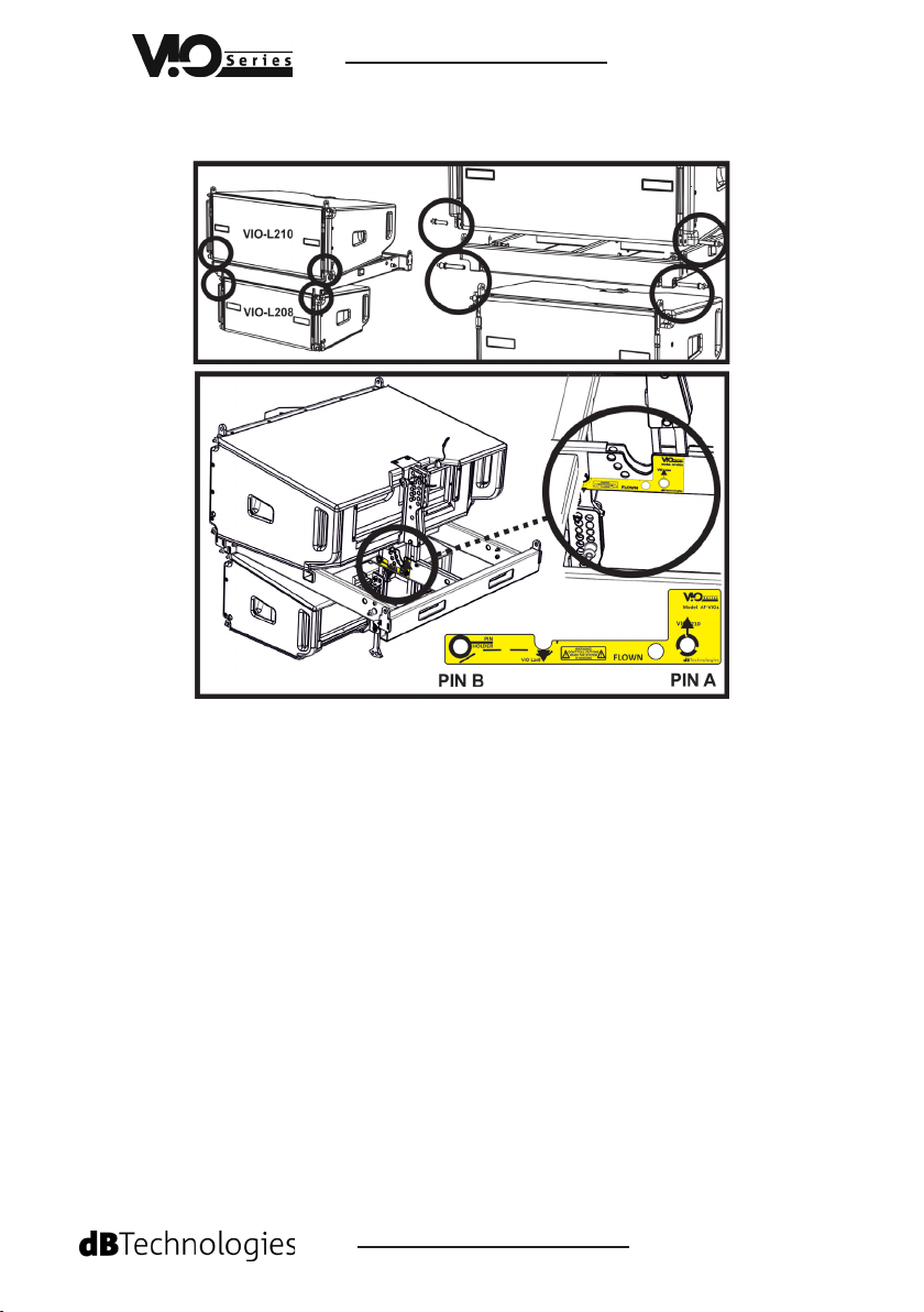
2. Montaggio FLOWN
2. FLOWN mounting
AF-VIO1
A VIO-L208 sotto ViO-L210 (è mostrato l’aggancio solo di 1 VIO-L208 sotto a VIO-L210)
VIO-L208 under VIO-L210 (it is shown only the mounting of a VIO-L208 under a VIO-L210)
VIO-L210
• Sul lato frontale dello speaker estrarre i pin.
On the front side of the speaker extract the pins.
• Inserire ed agganciare con i pin di VIO-L210 le staffe [A] di AF-VIO1.
Insert and fasten with the pins of VIO-L210 the [A] brackets of AF-VIO1.
• Sul lato posteriore estrarre il PIN A (mostrato in gura) ed osservando le indica-
zioni dell’etichetta di AF-VIO1 inserire il giunto posteriore di VIO-L210. Reinserire il
pin ed assicurarsi che blocchi correttamente il montaggio.
On the rear side extract the A pin (shown in the picture) and, following the label of AF-
VIO1 insert the rear joint of VIO-L210-. Insert then the pin and check that the mouning is
properly fastened.
VIO-L208
• Sul lato frontale estrarre i pin.
On the front side of the speaker extract the pins.
• Alzare e ssare i giunti superiori dello speaker ed inserirle nelle sedi [B] di AF-VIO1,
ssandole coi pin.
• Lift and fasten the upper joint of the speaker and insert them in the housings [B] of
AF-VIO1
• Sul lato posteriore estrarre il pin B rilasciando il giunto [F] di AF-VIO1 ed inserirlo
nella staffa sul retro di VIO-L208, bloccandolo col pin.
On the rear side, extract the [B] pins releasing the joint [F] of AF-VIO1 ed insert it in the
rear bracke of VIO-L208, fastening it with the pin.
FOT000100 REV.1.1
Page 3

AF-VIO1
B VIO-L208 sotto ViO-S118 (è mostrato l’aggancio solo di 1 VIO-L208 sotto a VIO-S118)
VIO-L208 under VIO-S118 (it is shown only the mounting of a VIO-L208 under a VIO-S118)
VIO-S118
• Estrarre i pin sul lato inferiore del subwoofer, sia anteriormente che posteriormente.
Extract the pins on the lower side of the subwoofer, frontally and on the rear side.
• Inserire ed agganciare le staffe [A] ed [E] di AF-VIO1 (4 punti) con i pin di VIO-S118.
Insert and fasten the [A] and [E] brackets of AF-VIO1 (4 points)
VIO-L208
• Sul lato frontale dello speaker estrarre i pin.
On the front side of the speaker extract the pins.
• Alzare e ssare i giunti superiori dello speaker ed inserirle nelle sedi [B] di AF-VIO1,
f issandole coi pin.
• Lift and fasten the upper joints of the speaker and insert them in the housings [B] of
AF-VIO1
• Sul lato posteriore estrarre il pin B rilasciando il giunto [F] di AF-VIO1 ed inserirlo
nella staffa sul retro di VIO-L208, bloccandolo col pin.
On the rear side, extract the [B] pins releasing the joint [F] of AF-VIO1 ed insert it in the
rear bracket of VIO-L208, fastening it with the pin.
Le caratteristiche, le speciche e l’aspetto dei prodotti sono soggetti a possibili cambiamenti senza previa comunicazio
ne. dBTechnologies si riserva il diritto di apportare cambiamenti o miglioramenti nel design o nelle lavorazioni senz
assumersi l’obbligo di modicare o migliorare anche i prodotti precedentemente realizzati.
Features, specication and appearance of products are subject to change without notice. dBTechnologies reserves the
right to make changes or improvements in design or manifacturing without assuming any obligation change or impr
ve products previously manufactured.
FOT000100 REV.1.1
Page 4

AF-VIO1
3. Montaggio STACK
3. STACK mounting
ES. VIO-L208 su ViO-S118R (è possibile anche l’uso di moduli VIO-L210 ed altri tipi di sub)
ES. VIO-S208 on VIO-LS118R (it is possible also the use of VIO-L210 modules and other sub
models)
VIO-S118R
• Agganciare le staffe [D] di AF-VIO1 coi relativi pin alle sedi posizionate sul top del
subwoofer.
Fasten the brackets [D] of AF-VIO1 with the related pins in the housings placed on the top
of subwoofer.
VIO-L208
• Sul lato frontale sollevare le staffe retraibili [C] di AF-VIO1.
On the front side lift the retractable brackets [C] of AF-VIO1.
• Inserire e bloccare coi pin su queste staffe gli agganci inferiori di VIO-L208.
Insert and fasten the pins on those brackets the fastening system of VIO-L208.
• Sul lato posteriore selezionare l’angolo desiderato tra i possibili: +5°, 0°, -2.5°, -5°.
On the rear side select the desired angle between: +5°, 0°, -2.5°, -5°
• Bloccare in posizione stack il braccio posteriore di VIO-L208 col pin C dello speaker.
Fasten in stacked position the rear arm of VIO-L208 with the C pin of the speaker.
• Inserire e bloccare col pin A di AF-VIO1 il braccio nella posizione desiderata.
Insert and fasten with the A pin of AF-VIO1 the arm in the desired position.
NOTA SULL’UTILIZZO DI VIO-L210 AL POSTO DI VIO-L208: sul lato frontale gli agganci di AF-
VIO1 sono quelli [A], sul retro il giunto di VIO-L210 si ssa nella posizione indicata in etichetta,
inserendo poi il pin A come mostrato in gura.
NOTE ON THE USE OF VIO-L210 INSTEAD OF VIO-L208: on the front side the fastening system is the
[A] one of AF-VIO1, on the rear side the joint of VIO-L210 is fastened in the position shown by the
label, inserting then the A pin as shown in the picture.
CONFIGURAZIONI AMMESSE IN STACK*
ADMITTED STACKED CONFIGURATIONS*
• Installazione stack:
Stack installation:
* Per congurazioni che eccedano questi limiti, è obbligatorio un ssaggio addizionale con cinghie o mezzi meccanici non forniti. I
limiti own sono determinati dall’utilizzo di dBTechnologies Composer.
* For congurations that exceed those limits, it is mandatory the use of a fastening system with straps or mechanical means (not
supplied). The own maximum limits are calculated with dBTechnologies Composer.
A.E.B. Industriale Srl Via Brodolini, 8 Località Crespellano 40053 VALSAMOGGIA BOLOGNA (ITALIA)
Tel +39 051 969870 Fax +39 051 969725 www.dbtechnologies.com info@dbtechnologies-aeb.com
max 4 VIO-L208 o 3 VIO-L210 su
max: 2 VIOS318 o S218 - 1 S118 o S118R
FOT000100 REV.1.1
 Loading...