

Usage Manual

2
I. Usage Notice
II. Installation Method
◆Name of Various Parts
◆Installation of Power Wheel
◆Installation of Power-off Brake Levers
◆SENSOR Installation
◆Installation of Console
III. Operation Instructions of Console
IV. Charging Method
◆To Charge The Console
◆To Charge The Power Wheel
V. Maintenance & Repair
◆Maintenance
◆Simple Repair Instruction
VI. Error Code (Diagnosis Message)
VII. Specification
dbRevO Usage Manual
03
04
05
06
07
08
09
12
12
13
13
14
15

3
I. Usage Notice (Foreword)
Be sure to read and abide by following instructions
then abide by traffic
rules for your driving safety. Products may be damaged to endanger personal
life safety if there is any violation.
1. Be sure to wear safety helmets when driving bicycles.
2. Power wheel may be damaged with speed deceleration due to
passengers or heavy articles.
3. Users shall prevent batteries from being affected with damp when driving
across low-lying water.
4. It is strictly prohibited to reconstruct wheel body or detach parts to avoid
reduction of products life of power wheel.
5. Be sure to inspect and maintain periodically to reduce failures.
6. It is strictly prohibited to drive on excessively instable pavement to avoid
damaging power wheel.
7. It is strictly prohibited to use assistance power for slope section to avoid
danger.
8. Motor will stop power supply automatically. if super-high motor
temperature is caused by continuous climbing. Climbing slope is limited
to 13°
9. Users shall pay attention to pits, stones on roads and rails, etc which may
deviate from driving direction at any time during driving.
10. Users shall stop driving if driving safety is influenced by damaged parts
during driving.
11. It is suggested to use parts of original manufacturer according to
replacement demand.
12. Power wheel is originally designed for urban usage. It is strictly prohibited
to use in following locations such as cross-country, athletics or instable
pavement to avoid personal injury or bicycle damage.
13. Users shall stop driving and take care of it as soon as possible if there is
noise or sound under abnormal conditions.
14. It is strictly prohibited to use solvent or other chemical medicine on
battery cell. It can be wiped by dipping cloth by water.
15. Note! Users can not reconstruct power wheel easily.
4
II. Installation Method
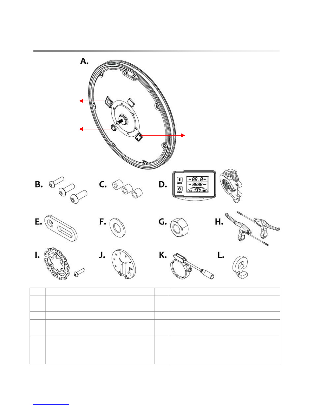
◆Name Of Various Parts:
A Power wheel G Screw capx2
B
Truss headhexagon screws
(M4,M5,M6)
H Power-off brake levers
C Sleeve (M4,M5,M6) I Disc brake +Screw x 6 (optional)
D Console J Magnetic disc for sensor
E Front fork fixation piece K sensor
F
Washer x 7
(Users shall install the washer
according to the space between
front fork)
L
Axle center fixation sheet iron
(NT-2881)
Power switch
Charging hole
Software updating
location
5
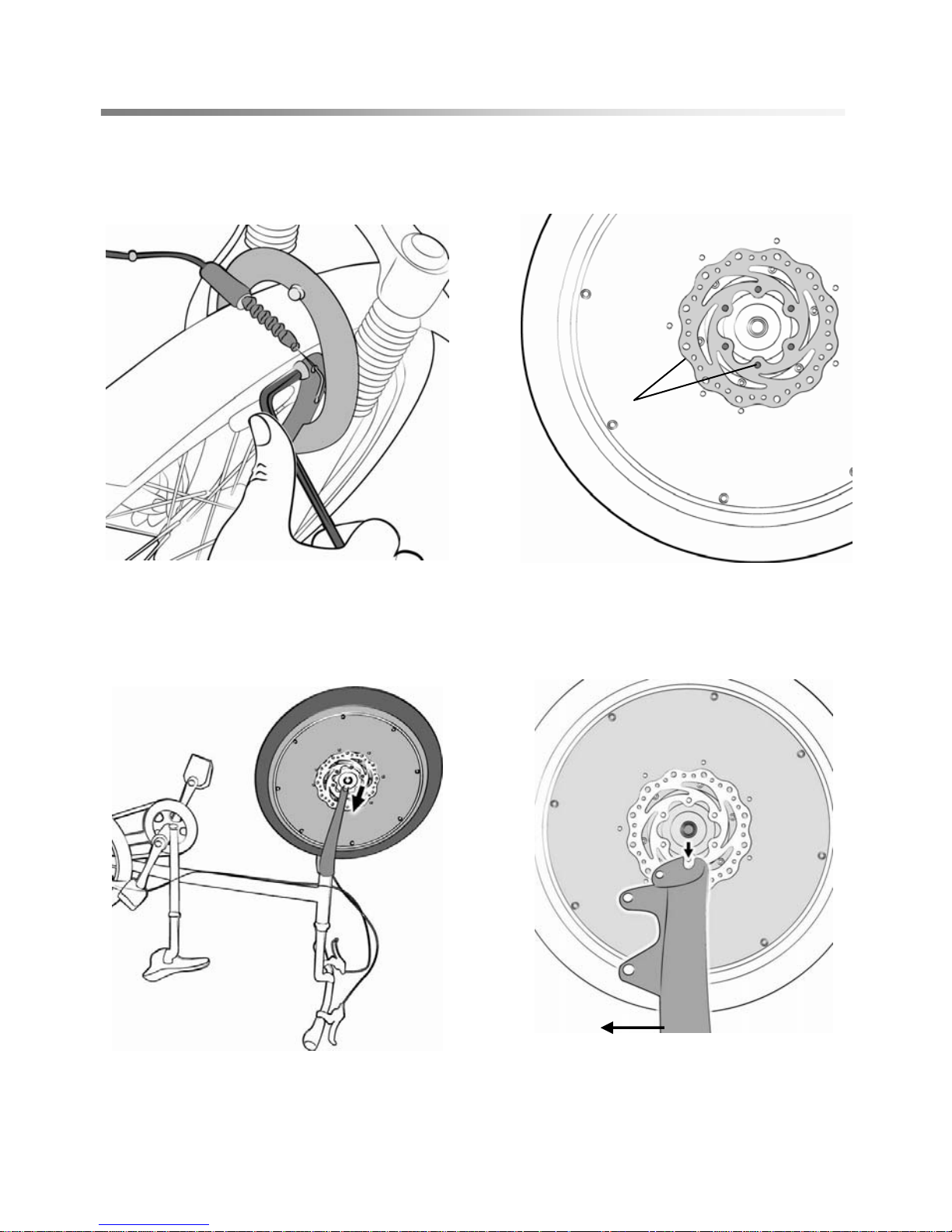
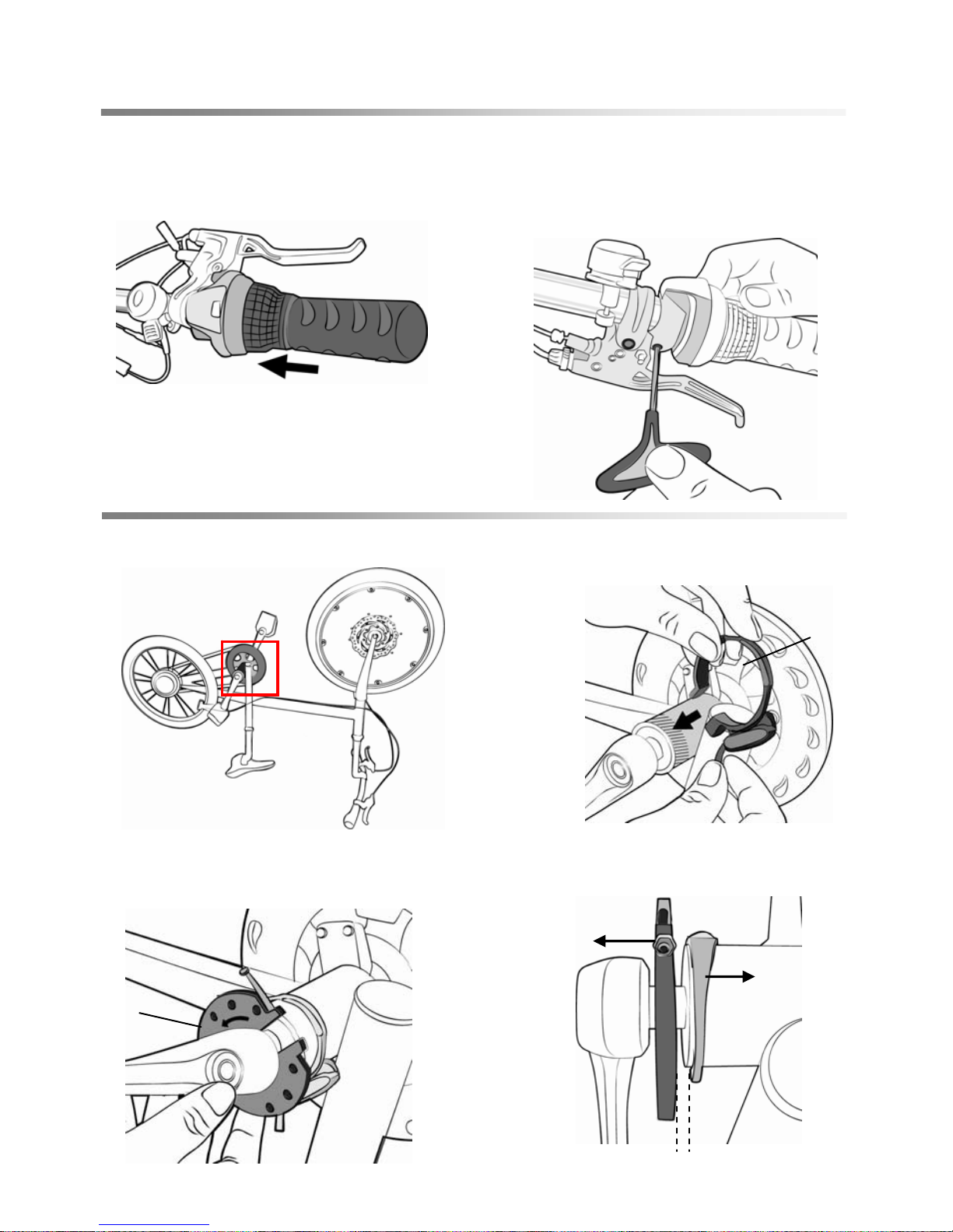
◆Installation Of Power Wheel:
1. To detach front wheel brake wire
of general bicycle and front wheel.
(Be sure to detach the entire brake
for installation of optional disc
brake.)
2. To lock alignment position of disk
brake by screw properly. (Disc brake is
optional.)
3. To invert the bicycle and place
power hole of power wheel in right
side then place (optional) disk brake
in left side into front fork.
4. To align center of power wheel to
front fork connector.
Front fork
I.
6
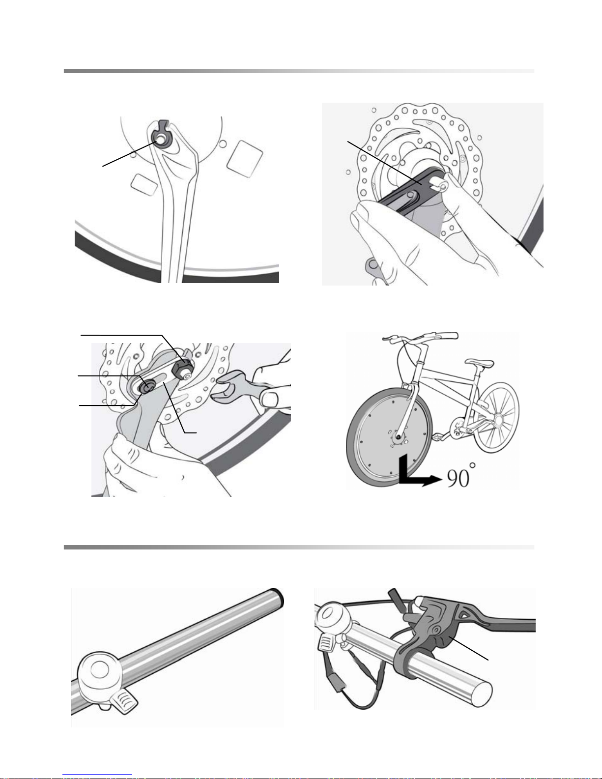
◆Installation Of Power Wheel:
◆Installation Of power-off Brake Levers:
B.
E.
G.
F.
10. To install H. and connect brake
wires.
9. To detach handlebar grips, original
brake levers and gearshift lever by
tools.
6. To align E. to axle center.5. To align L. into groove and place
into axle center (in charging side)
for lockin
g
.
H.
8. To check if tyre is perpendicular to
ground or not.
L.
E.
7.To install B. onto F. and place into E.
for lock (according to B.C. conditions).
To install axle center onto G. then lock.
7
Magnetic
disc
sensor
2-3mm
◆Installation of power failure handle:
◆SENSOR installation:
11. To install back the gearshift
lever and handlebar grips.
12. To adjust power-off brake levers
and gearshift lever for proper angle
then lock. To fix brake wires then test
brake repeatedly to see if it functions
well.
14. To place K outward and lock at the
part highlighted with oblique line shown
in the photo.
13. To invert the bicycle for sensor
installation.
15. Place magnetic disc into it and
arrow direction on magnetic disk must
be consistent with
p
edal movement
16. The peoper gap between
magnetic disc and sensor is 2-3mm.
Tighten the magnetic disc by nut.
K.
J.

8
◆Installation Of Console:
17. Install the bracket on the
handlebar.
18. Insert console into bracket.
19. Connect wires to finish the
installation.
Detachment method is opposite to above steps.
Note! Users shall store detached power wheel properly for best
condition.
9
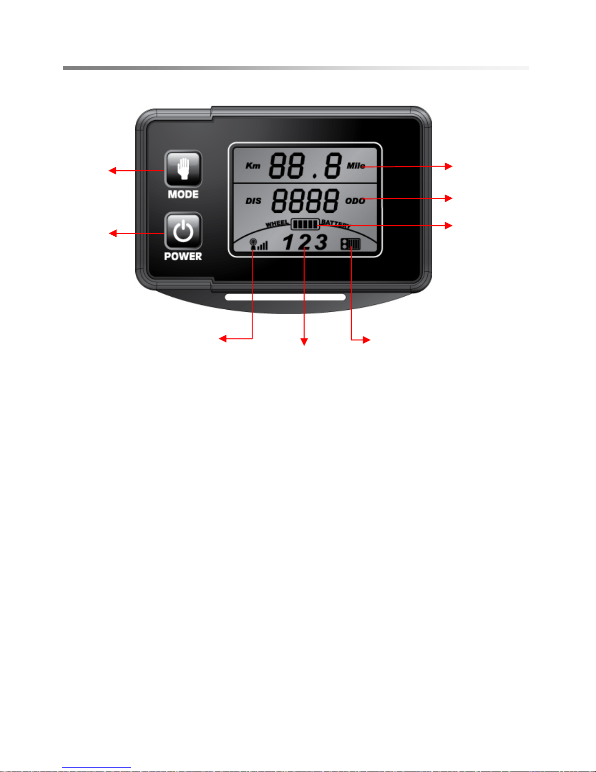
III. Operation Instructions Of Console
◆Istructions of data readout on console
(a) Speed:
Display the speed per hour of the bike by KM/H(Mile), speed range: 0~99.9.
Note: The speed shown by KM/H or Mile has been pre-set up.
(b)DIS/ODO:
Positive number—Distance counting is set to 0.
Distance increases from 0000 to 9999 by 1km/h(mile). When the distance is
over 9999, the system will automatically reset and record from 0.
Assistant
driving force
levels
Power
switch
Indicator of
battery
capacity for
Power wheel
2.4G wireless
transmission signal
Indicator of battery
capacity for console
assistance
level
selection
Mileage
Speed

10
◆Operation Instructions Of Console
(c)
Indicator of battery capacity for Power wheel
Energy column will display full number (namely, 5 BARs) when power volume is
full. BAR will flicker (with frequency of once every second) if there are only 2 BARs.
It will begin to flicker and alarm to notify users of charging need.
The battery indicator will display full 5 BARs when fully charged. BAR will flicker
(with frequency of once every second) if there are only 2 BARs It will begin to
flicker and as an alarm to notify users of charging need.
(d)
Battery volume display of electronic watch
Energy column will display full number (namely, 5 BARs) when power volume is
full. BAR will flicker (with frequency of once every second) if there are only 2 BARs.
It will begin to flicker and alarm to notify users of charging need.
The battery indicator will display full 5 BARs when fully charged. BAR will flicker
(with frequency of once every second) if there are only 2 BARs It will begin to
flicker and as an alarm to notify users of charging need.
(e)
2.4G wireless transmission signal display
Full signal (of 4 BARs) refers to strong transmission signal and no signal (of 0 BAR)
means the transmission stops.
(f)
Power switch
Power switch function of console: Press to turn on the console with blue
backlight; press again to turn off the console.
(g)
Auxiliary power set key
● Press to select the assisted power level from none, level 1, level 2 and level 3.
● Console only displays SPEED and DISODO when selecting no assisted power.
● The assisted power will supply according to the selected level (from level 1 to
level 3) when users start pedaling.
● Controller shall supply assisted power instantly when receiving the signal from
speed sensor. It will cut off power supply instantly when speed reaches 24.5KM.
11
◆Operation Instructions Of Console
Other operation supplementation instructions:
1. flickers when user brake the power-off brake.
2. Integrated energy-saving technology will power off the system if the bike
stopped for more than 15 minutes. To re-start the system, user has to
switch off the power for 3 to 5 seconds before to power on again.
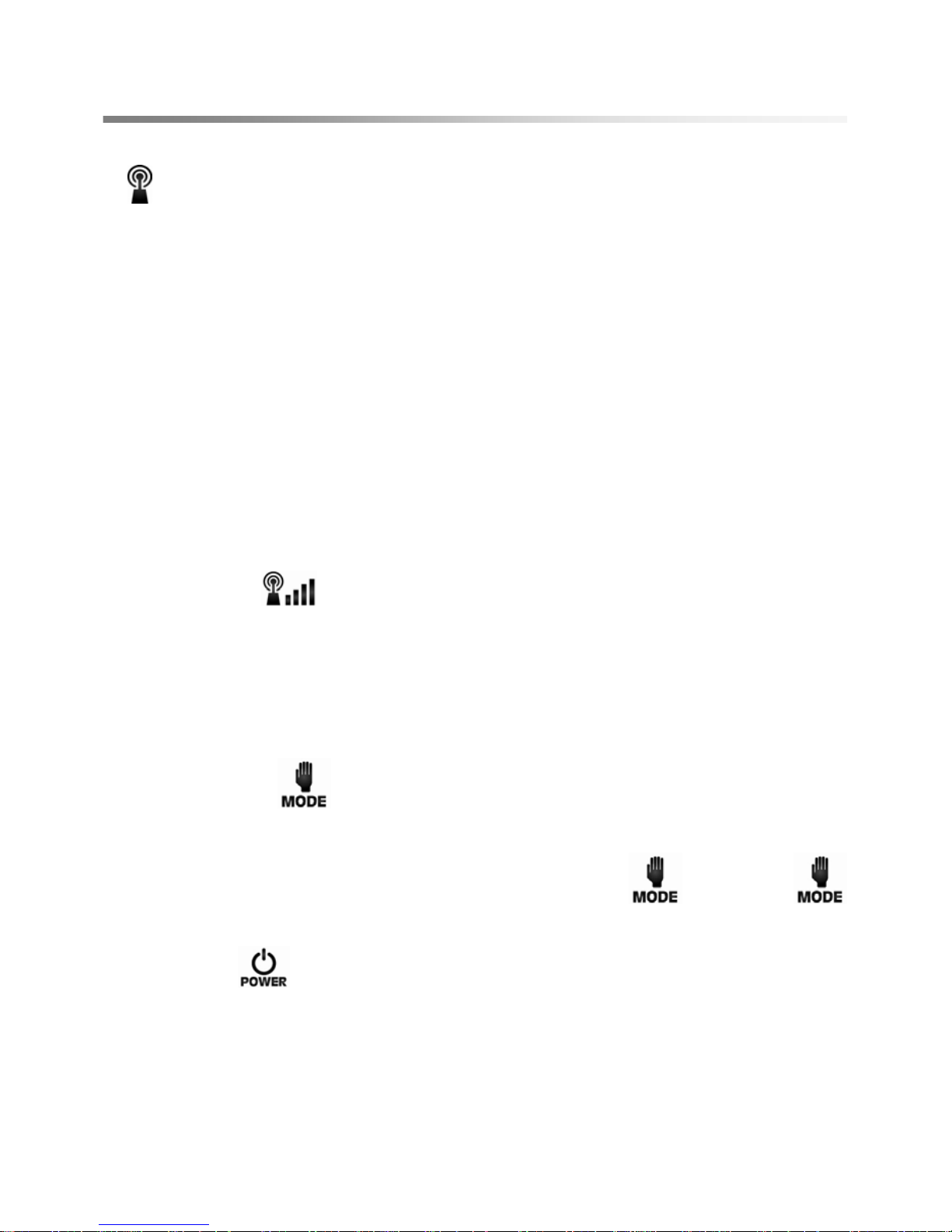
3.The console and controller will communicate through 2.4G wireless
transmission when use dbRevO wheel for the 1
st
time.
4. Users shall power on the wheel before power on the console. After the
console and controller communicate through 2.4G wireless transmission,
user will see
which means the communication is successful. If to
power on the console before to power on the wheel, error code E-0 will
flicker on the console screen.
5. Wheel size setup
● User shall press
key for 10 seconds to enter into wheel size setup
under standby mode, when not braking the power-off brake. .
● To select the wheel size from 16-30 inch by pressing
key. Press
once to increase 2 inch each time.
● Then, press
key to save the setup and return to standby mode

12
IV. Charging Method
◆To Charge The Console:
z Charging time is about 3-4 hours. Be sure to charge the console for 12
hours before using the battery for the 1
st
time.
z Suitable ambient temperature for charging is 0~45℃.
z Users shall charge the battery immediately after using, and to charge at
least once every month for better maintenance.
z Meanings of the LED colors on console charger.
Orange LED Red LED Orange LED
Standby:
Power supply
In charging Full charged
◆To Charge The Power Wheel:
z Charging time is about 4-6 hours. Be sure to charge the console for 12
hours before using the battery for the 1
st
time.
z Users shall use the charger provided by the original manufacturer. It is
strictly prohibited to use charger from other manufacturers randomly.
z Suitable ambient temperature for charging is 0~45℃.
z Users shall charge the battery immediately after using, and to charge at
least once every month for better maintenance.
z Meanings of the LED colors on dbRevO Wheel charger.
Green LED Orange LED Green LED
Standby:
Power supply
In charging Full charged

13
V. Maintenance and Repair
◆Maintenance:
1. To check if there’s any rusty part or leaks carefully. Leaks may be eroded
to accelerate damage and enlarge the leaks itself.
2. To clean dbRevO wheel periodically and keep away from all corrosive
materials such as salt.
3. Do not polish, drill or carve on wheel surface. Leaks may be caused by
large scratch, chisel hole or nick.
4. Users shall pay attention to find out noise source if any, and try to solve
the problems as soon as possible.
5. It is strictly prohibited to wash the wheel by strong spout to avoid
damaging the battery. Users shall clean the wheel by clean mop.
6. Users shall use neutral or soft detergent to avoid damaging the wheel
housing.
7. It is strictly prohibited to clean the wheel by sea water or salty water. Users
shall use cold water to avoid corrosion problems.
8. It is suggested to park the bicycle indoor or at cool places to avoid being
exposed to the sun and rain. Users shall keep the wheel dry to avoid rusty
problems. .
9. It is strictly prohibited to drop or to dash against the wheel. Huge external
force may cause the deformation and damage the internal electrical parts,
which is dangerous for users safety.
◆Simple Repair Instruction
1. To inspect the safety mark on the tire and to replace new tire instantly if
abrasion exceeds the mark.
2. To inspect the front and rear brakes and parts of the bike to see if any
operation fails, wire disconnection, or damage problems.
3. To keep the tire pressure within the marked scope on the tire because tire
may be burst when driving.
4. To check if there is chapping, damage or abnormal abrasion on tire or not.
Users shall replace a new tire instantly if it is damaged severely.
5. To check if there is excessive abrasion for brake pad or not. It shall be
replaced to avoid inflexible brake.

14
VI. Error Code
Error Code will flicker when control system is under abnormal conditions.
The console will be powered off automatically after Error Code flickers for 10
seconds.
Troubles And Troubleshooting
Trouble
code
Trouble Description Troubleshooting
1. To check if motor signal wire is disconnected.
E1
No speed signal from
motor during driving.
2. To replace motor.
E3
Controller fails when
motor operates
1. To replace control board.
E4
Controller fails when
motor operates.
1. To replace control board.
1. To check if Torque Sensor zeroing voltage setting is correct.
2. To check if Torque Sensor signal wire is disconnected.
E7
Torque Sensor voltage
is abnormal or out of
the scope of standard.
3. To replace Torque Sensor.
1. To check if motor signal wire is disconnected.
2. To replace motor.
E-8
UVW wire is
disconnected when
motor operates.
3. To replace lower controller.
1. To replace motor.
E-9
Short-circuit after
motor start-up
2. To replace lower controller.
1. To check if motor signal wire is disconnected.
2. To replace motor.
E-A Motor cannot operate
3. To replace lower controller.
E-B
Controller current is
over the scope of
standard.
1. To replace motor.
1. To power on the console after the battery is placed well and
switch on for 3-5 seconds.
As the console and controller are checking the battery
capacity after the battery is switched on. To power on the
console within 3-5 seconds, E-0 will flickers on the console.
2. To check if battery voltage is lower than 16V or not. If yes, to
charge the battery to full.
E-0
Battery voltage is
lower than the scope
of standard
3. To replace console
●Users shall contact with local dealers if troubles still cannot be solved under
above situations!
15
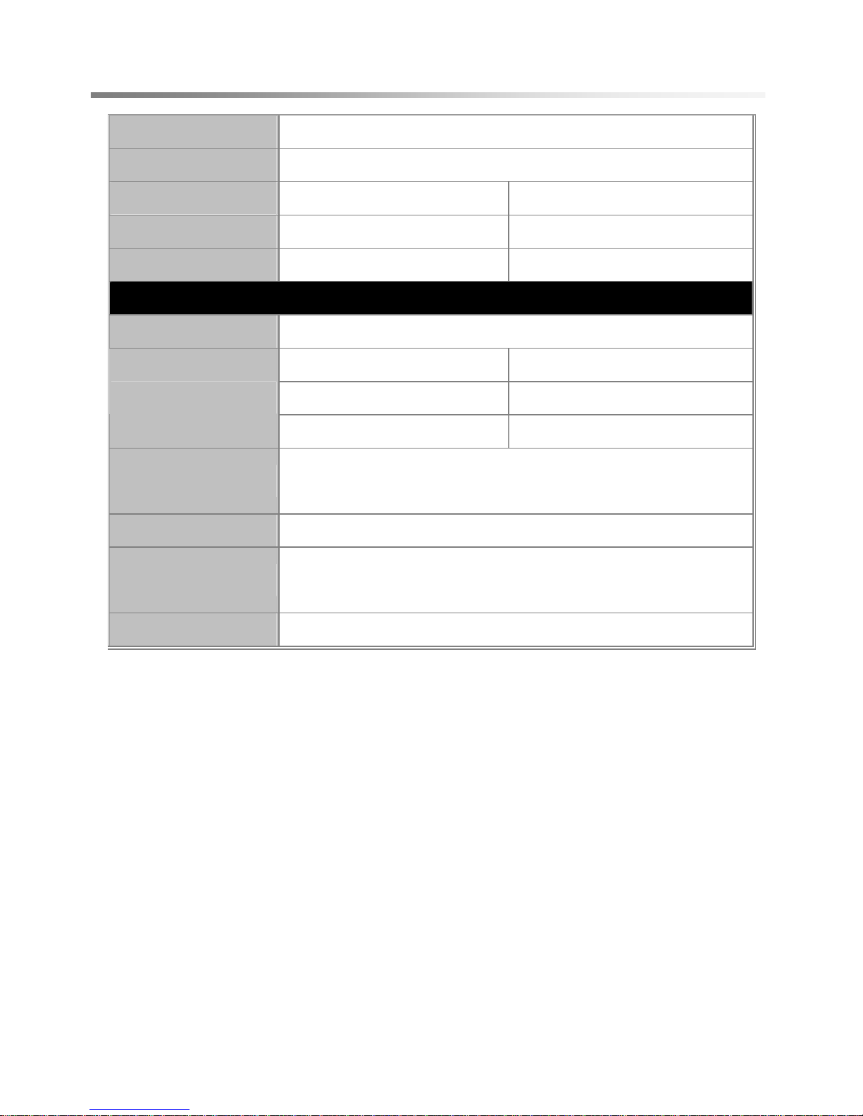
VII. Dimension Form
Color Many options
Battery Housing Specification
Wheel rim 26" Alu-alloy 20'' Alu-alloy
Tire 26''X1.95 20''X1.95
G.W. 26'':8.6 kgs 20'':6.4 kgs
Power System Specification
Motor 24V250W DC Brushless
26'' 20''
24V8Ah Lithium Battery 24V6.6Ah Lithium Battery
Battery
Optional 11A Optional 8.8A
Charger
24V2A charger for battery &
5V500mA USB charger for console
Display LCD Console (Quick-released, wireless)
Sensor Device
Speed Sensor Inside Motor or
Wireless Speed Sensor for pedelec
Power-Off Brake Easy-installed Power-off Brake
2011/4/11 V1.0
 Loading...