

DBLTek ROIP302 Series, RoIP302M, RoIP302GM, RoIP302G User Manual
ROIP302 Series User menu
Cross-Network Gateway
(Radio, VOIP, GSM, Public Announce)
User Manual
ROIP302 Series
Version:1.0
2010-7-13
For environmental protection, please view this manual
electronically and only print the pages you need.
www.dbltek.com

ROIP302 Series User menu
Content
1、 Important Notices
2、 Gift Box Check List
3、 Overview
4、 Installation
5、 Default Factory Settings
6、 Web Configurations
7、 Call Settings
8、 Operating Instructions
9、 Application Examples
10、 Hardware Specifications
11、 Software Specifications
12、 Miscellaneous
13、 Troubleshooting
www.dbltek.com

ROIP302 Series User menu
1 Important Notices
1、 This product is used to link up the civilian radio network, internet, and cellular phone
network. Its operation and performance rely on the broadband network connections via
private and/or public networks and the cellular phone networks. Due to the stability and
reliability of these networks, this product may not be able to link up all the networks
connected without any interruptions. Therefore, it is not recommended to use this
product in an emergency system or a communication system with zero-failure.
2、 This product can bridge and extend radio networks all over the world. Please consult
your local regulations in order to use this product legally.
3、 This product requires the use of dynamic DNS (DDNS) service. For testing purpose,
this DDNS service is temporary provided for free by DBL Technology (Hong Kong).
However, this service is not guaranteed without any interruptions. Customers are urged
to build their own DDNS server or obtain this service from a DDNS provider. Free
DDNS server software may be obtained freely from your local network service provider.
4、 Customers and/or users are taking full responsibilities and all risks in using this product.
We are not responsible for any direct or indirect losses caused by, but not limited to,
communication failures as a result of product failure or network problems.
CUSTOMERS ARE ASSUMED TO HAVE READ AND ACCEPTED WITH FULL
UNDERSTANDINGS OF THE IMPORTANT NOTICES STATED ABOVE.
2 Gift Box Check List
Upon unpacking the gift box, please check carefully that all items listed below are included.
Please report to your supplier for any missing items immediately.
Item Appearance
Description
www.dbltek.com
ROIP302 Series User menu
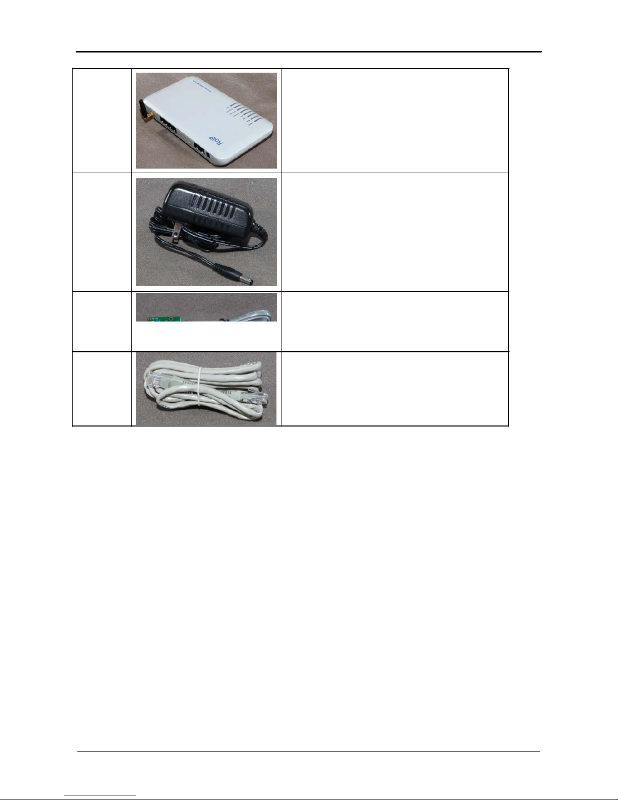
1.
2.
3.
4.
1 x Main Unit
1 x AC/DC Adapter
Input: 110/220VAC
Output: 12VDC, 2A
3 x PTT Adapter Cables
1 x Ethernet Cable
www.dbltek.com

ROIP302 Series User menu
3 Overview
The fundamental of RoIP(Radio over IP)technology is to convert the audio and PTT signals in a
radio terminal into IP packets and then transmit the data via the IP networks. The challenge in this
technology is to insure that the audio is transmitted in real time and the PPT control signal is
transmitted immediately and reliably. The radio range is general limited by the restricted
transmitting power, the antenna sensitivity, and other environmental factors. The success
deployment of this technology extends the coverage of a radio network without using expensive
repeaters or links up multiple radio networks in the world. In addition, this technology can also link
up the radio world to the VoIP world and the cellular world easily. It truly makes voice
communications across multiple networks possible.
RoIP302 series is developed based on VoIP technology to realize RoIP functions in order to create
a new type of gateway to bridge voice communications across multiple networks (Radio, Cellular,
VoIP). Its main advantages are low bandwidth usage, high fault tolerant, low loss in voice quality,
fast response, easy installation and configuration. It is ideal for setting up a private network with
multiple voice communication platforms, a distributed network for remote management, a network
with extended coverage, and an integrated network of multiple amateur radio networks.
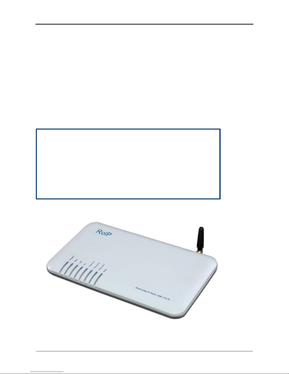
RoIP302 Series Cross-Network Gateway has 3 PTT interfaces. Up to 3 audio channels from
radio networks can be connected to the RoIP302 simultaneously. All 3 channels can be
programmed into the same or different groups in order to bridge real time voice communications to
various network interfaces.
RoIP302 Series has a built-in GSM / CDMA cellular phone module, user can access the radio
networks connected via the cellular network installed. A radio terminal equipped with DTMF
generation capability can make an outgoing call via the cellular network as well. This links up the
two networks which cannot be linked up via any traditional means.
RoIP302 Series gateway can also be a remote ON/OFF Switch. User can control the built-in
relay to switch on or off the devices that are under control. These devices could be an alarm signal,
a light, a public announce system, an electronic lock, etc.
RoIP302 Series gateway supports routing of IP voice stream to via a recording server. Voice
records can then be saved to a hard disk and can be retrieved at any time for examinations.
RoIP302 Series gateway can be installed in IP networks with intranet or internet connections via
ADSL modem, Cable modem, or Local Area Network (LAN). The unique built-in DDNS client
can help to simplify the installation and configuration without relying on a voice relay server in order
to achieve interconnections among RoIP302 Series gateways.
www.dbltek.com
ROIP302 Series User menu
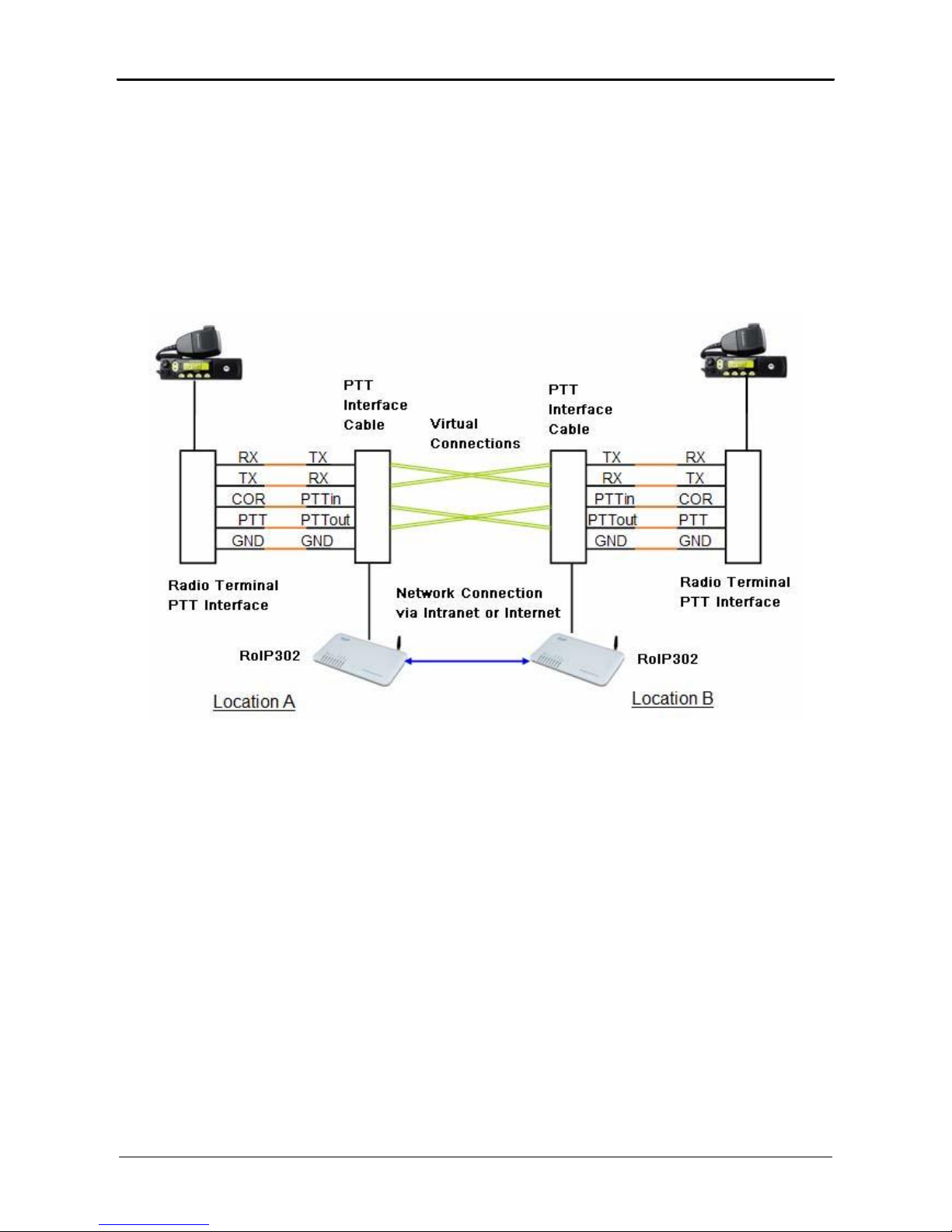
3.1 Theory of Operation
The diagram below shows the concept of how RoIP bridge the voice communication two radio
terminals at two different locations. The PTT Interface Cable provided is used to connect
between the RoIP and the radio terminal. Please note how the signals are passing between these
two devices. The connection between the two RoIP302s is through internet or intranet. The
green lines actually show how the audio and the PTT control signals are transmitted between the
two radio terminals. The two RoIPs have created a virtual connection between the two radio
terminals.
3.2 Modes of Operation
With different options, RoIPs support both Point-to-Point Mode and Group Transmit Mode
operations. Please refer to Section 3.4 for more RoIP versions available.
There are two types of RoIPs: RoIP302 and RoIP302M. RoIP302s cannot only support
Point-to-Point operation. RoIP302M has a built-in SIP server for 12 clients (RoIP302 can only
support one client) and group transmit capability. The additional feature in RoIP302M is the
built-in SIP server and the ability to transmit voice signal a maximum of 12 SIP Clients
simultaneously.
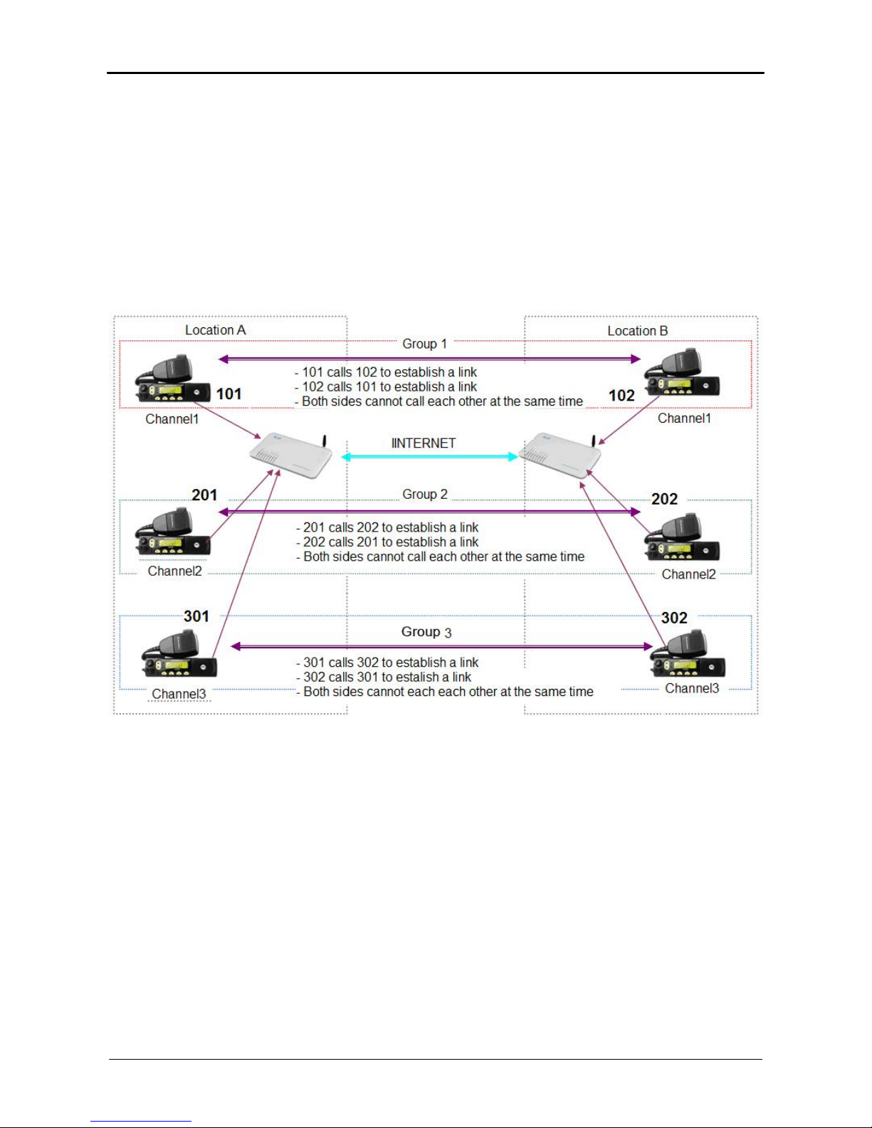
1. Point-to-Point Mode
In this mode, one RoIP302 is using public IP and the others could use public IPs of private
IPs with DDNS enabled. If the built-in SIP server is used, either one of the RoIPs can be a
www.dbltek.com
ROIP302 Series User menu
master and the other will register to the master. Please make sure that both RoIP302s do
not have the same Group SIP Number.
The diagram below demonstrates each RoIP302 are connected to 3 Radio Terminals. Each
terminal is assigned to a different group. The two RoIP are connected via a IP connection
as shown by the blue line. The PTT control signal is represented by the single purple lines
and the voice signals are represented by the double purple lines. When a voice
transmission is initiated from a channel, the RoIP302 will connect to the other RoIP302 in
order to establish a link with the corresponding channel automatically.
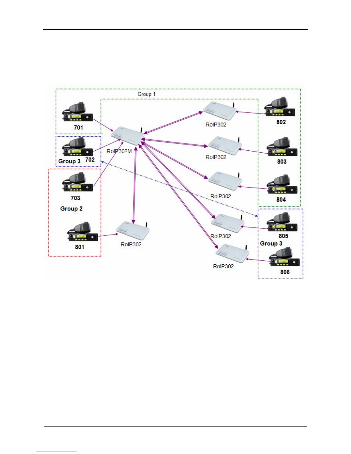
2. Group Transmit Mode
At least one RoIP302M is required to support the Group Transmit mode. This RoIP302M is
the master with its own unique Group SIP Number and offers its built-in SIP server for up to
12 RoIP302s (RoIP302M can also register as well for expansion) to register. The diagram
below shows only RoIP302s are used to register to the RoIP302M. Each RoIP302s must
have its unique Group SIP Number. A maximum of 12 RoIP302s can be deployed in this
example. Please note that only one one-way voice transmission is allowed at all time.
When a voice signal is transmitted from a RoIP302, RoIP302M will re-transmit the signal to
all other clients in the same group. If the voice signal is coming from a PTT port (radio
terminal) of the RoIP302M, the RoIP302M will re-transmit the voice signal to all other PTT
ports and SIP clients that are in the same group. For example, if Channel 802 talks, Channel
701, 803 and 804 can hear. If Channel 701 talks, Channel 802, 803, and 804 can hear.
www.dbltek.com
ROIP302 Series User menu
Please note that when more channels are used, the higher bandwidth is required and the poor
the performance of the system is. It is recommended that the user needs to insure sufficient
bandwidth is available and the network connection is stable before implementing a large
network. In general, intranet network is preferred in this case.
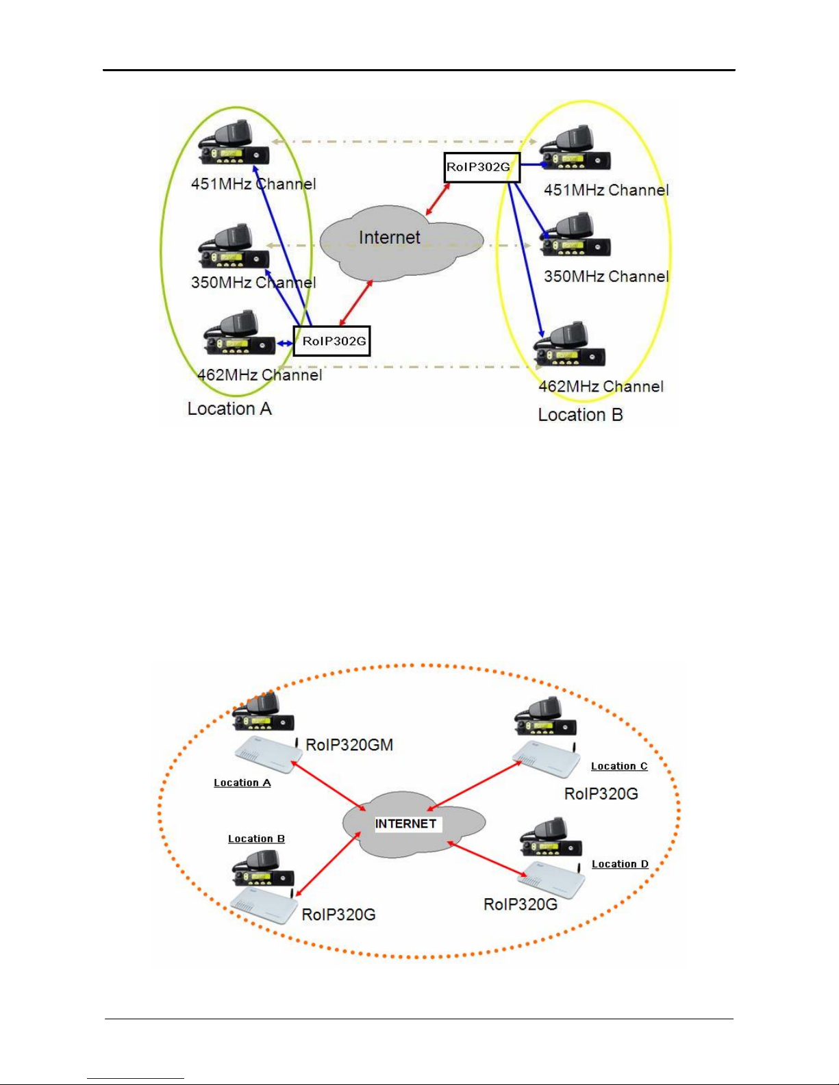
3.3 Application Examples
Application example 1: Link up radio network between two locations
- Using two RoIP302Gs to link up three radio channels in two different locations.
www.dbltek.com
ROIP302 Series User menu
Application example 2: Link up radio network at multiple locations
- As shown in the application diagram above, four locations can be linked up via one
RoIP302GM and three RoIP302G. The RoIP302GM has a built-in SIP server and the group
transmit capability to up to 12 SIP clients. By replacing one RoIP302G with RoIP302GM,
the system is now in Group Transmit Mode and up to 11 more RoIP302Gs can be added to
the system. Each RoIP302G now registers to the RoIP302M. This mechanism allows the
system to expand rapidly.
www.dbltek.com
ROIP302 Series User menu
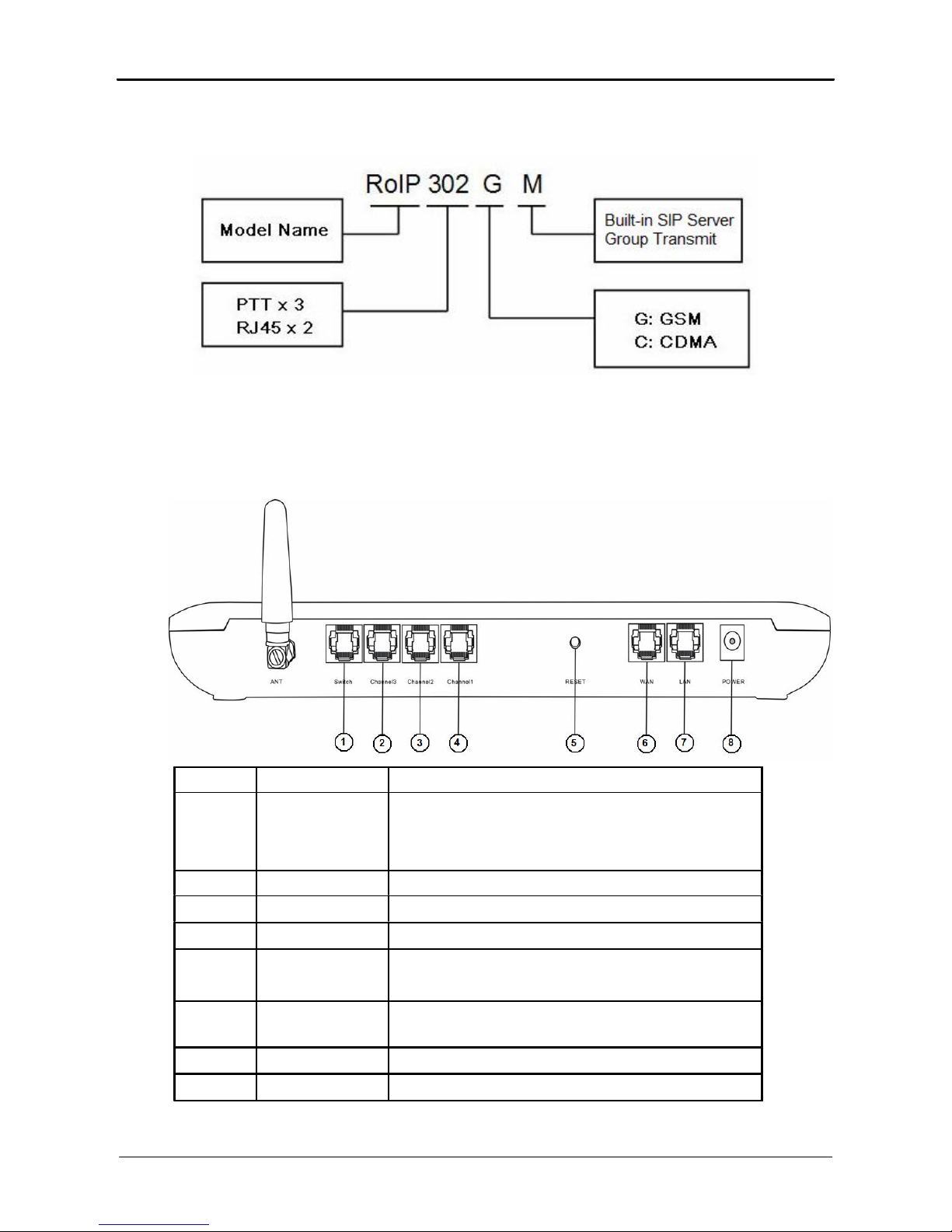
3.4 Model Nomenclature
4 Installation
a)Back Panel
Label
1
2
3
4
5
6
7
8
Name
Switch
Channel 3
Channel 2
Channel 1
Reset
WAN
LAN
Power
Description
Remote control: Relay switch with 220VAC input
and 500 mA load current.
6-pin RJ11port for PTT Adapter Cable
6-pin RJ11port for PTT Adapter Cable
6-pin RJ11port for PTT Adapter Cable
Press 10 seconds to reset the device to factory
defaults.
10/100Base-T WAN connection for external
access
10/100Base-T LAN connection
12V 1A
www.dbltek.com
 Loading...